1
1ST PRINTING
JULY-1998
TM
OWNER’S MANUAL
STD VERSION
SEGA ENTERPRISES, USA
MANUAL NO. 4201-6394-01
Warranty
Your new Sega Product is covered for a period of 90 days from the date of shipment. This certifies
that the Printed Circuit Boards, Power Supplies and Monitor are to be free of defects in workmanship or materials under normal operating conditions. This also certifies that all Interactive Control
Assemblies are to be free from defects in workmanship and materials under normal operating conditions. No other product in this machine is hereby covered.
Sellers sole liability in the event a warranted part described above fails shall be, at its option, to
replace or repair the defective part during the warranty period. For Warranty claims, contact your
Sega Distributor.
Should the Seller determine, by inspection that the product was caused by Accident, Misuse, Neglect, Alteration, Improper Repair, Installation or Testing, the warranty offered will be null and void.
Under no circumstances is the Seller responsible for any loss of profits, loss of use, or other damages.
This shall be the exclusive written Warranty of the original purchaser expressed in lieu of all other
warranties expressed or implied. Under no circumstance shall it extend beyond the period of time
listed above.
TABLE OF CONTENTS
INTRODUCTION OF THE OWNERS MANUAL
GENERAL PRECAUTIONS
1. PRECAUTIONS TO BE HEEDED FOR OPERATION
2. NAME OF PARTS
3. ACCESSORIES
4. ASSEMBLY AND INSTALLATION
5. PRECAUTIONS TO BE HEEDED WHEN MOVING MACHINE
6. CONTENTS OF GAME
7. EXPLANATION OF TEST AND DATA DISPLAY
7-1 COIN METER, INTERNAL SWITCHES, AND SWITCH UNIT
7-2 TEST MODE
7-3 MEMORY TEST
7-4 VIDEO MEMORY TEST
7-5 BOUNDRY TEST
7-6 INPUT TEST
7-7 OUTPUT TEST
7-8 SOUND TEST
7-9 C.R.T. TEST
7-10 TIMER TEST
7-11 GAME ASSIGNMENTS
7-12 COIN ASSIGNMENTS
7-13 VOLUME SETTING
7-14 BOOKKEEPING
7-15 BACKUP DATA CLEAR
8. CONTROL PANEL
8-1 GREASING
8-2 REPLACING THE EXTENSION SPRING
8-3 REPLACING THE TORSION SPRING
8-4 REPLACING THE VOLUME
8-5 REPLACING THE INTERNAL PARTS OF REEL
9. COIN SELECTOR
9-1 TAKING OUT THE COIN SELECTOR
10. MONITOR
10-1 CATUTIONS CONCERNING SAFE HANDLING OF MONITOR
10-2 CLEANING THE CRT SURFACES
10-3 ADJUSTMENT METHOD
10-4 REMOVAL/REPLACEMENT OF MONITOR
11. REPLACEMENT OF FLUORESCENT LAMP AND DISPLAY CARD
11-1 REPLACEMENT OF FLUORESCENT LAMP
11-2 REPLACEMENT OF DISPLAY CARD
12. PERIODIC INSPECTION TABLE
13. TROUBLESHOOTING
14. GAME BOARD
14-1 REMOVING THE GAME BOARD
14-2 COMPOSITION OF THE GAME BOARD
15. DESIGN RELATED PARTS
16. PARTS LIST
17. WIRING DIAGRAMS
1
2~3
4
5
6~7
8~12
13
14~22
23~36
24~26
27
27
28
28
29
29
29
30
30
31
32~34
35
36
36
37~43
37~38
38~39
40~41
42
43
44~46
44
47~52
47~48
48
49~50
51~52
53~54
53
54
55
56
57~58
57
58
59
60~89
XXX
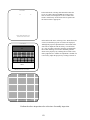
SPECIFICATIONS
Installation space:
37 in.(L) x 30 in.(W)
Height:
65 in.
Weight:
Approx. 223 lbs.
Power maximum current:
1.8 Amp AC 120V 60 Hz
MONITOR:
29” 3-mode scan display
INTRODUCTION OF THE OWNERS MANUAL
SEGA ENTERPRISES, LTD., has for more than 30 years been supplying various innovative and
popular amusement products to the world market. This Owners Manual is intended to provide
detailed descriptions together with all the necessary installation, game settings and parts ordering
information related to the SEGA BASS FISHING U/R, a new SEGA product.
This manual is intended for those who have knowledge of electricity and technical expertise, especially in ICs, CRTs, microprocessors, and circuit boards. Read this manual carefully to acquire
sufficient knowledge before working on the machine. Should there be a malfunction, non-technical
personnel should under no circumstances touch the interior system. Should the need arise, contact
our main office, or the closest branch office listed below.
SEGA ENTERPRISES, INC. (USA)
Customer Service
45133 Industrial Drive
Fremont, CA 94538
Phone 650-802-1750
Fax 650-802-1754
7:30 am - 4:00 pm, Pacific Standard Time
Monday thru Friday
1
General Precautions
Follow Instructions: All operating and use instructions should be followed.
Attachments: Do not use attachments not recommended by the product manufacturer as they may cause hazards.
Accessories: Do not place this product on an unstable cart, stand, tripod, bracket, or table. The product may fall,
causing serious injury to a child or adult, and serious damage to the product. Use only with a cart, stand, tripod, bracket, or
table recommended by the manufacturer, or sold with the product. Any mounting of the product should follow the
manufacturer’s instructions, and should use only mounting accessories recommended by the manufacturer.
Moving the Product: This product should be moved with care. Quick stops, excessive force, and uneven surfaces
may cause the product to overturn.
Ventilation: Slots and openings in the cabinet are provided for ventilation, to ensure reliable operation of the product
and to protect it from overheating; these openings must not be blocked or covered. The openings should never be blocked
by placing the product in a built-in installation such as a bookcase or rack unless proper ventilation is provided or the
manufacturer’s instructions have been adhered to.
Power Sources: This product should be operated only from the type of power source indicated on the marking label.
If you are not sure of the type of power supply to your location, consult your local power company. For products intended
to operate from battery power or other sources, refer to the operating instructions.
Grounding or Polarization: This product is equipped with a three-wire grounding-type plug, a plug having a third
(grounding) pin. This plug will only fit into a grounding-type power outlet. This is a safety feature. If you are unable to
insert the plug into the outlet, contact your electrician to replace your obsolete outlet. Do not defeat the safety purpose of the
grounding-type plug.
Power Cord Protection: Power-supply cords should be routed so that they are not likely to be walked on or pinched
by items placed upon or against them, paying particular attention to cords at plugs, convenience receptacles, and the point
where they exit from the product.
Overloading: Do not overload wall outlets, extension cords, or integral convenience receptacles as this can result in
a risk of fire or electric shock.
Object and Liquid Entry: Never push objects of any kind into this product through openings as they may touch
dangerous voltage points or short-out parts that could result in a fire or electric shock. Never spill liquid of any kind on the
product.
Servicing: Do not attempt to service this product yourself as opening or removing covers may expose you to dangerous voltage or other hazards. Refer all servicing to qualified service personnel.
Damage Requiring Service: Unplug this product from the wall outlet and refer servicing to qualified service personnel under the following conditions:
a) If the power cord or plug is damaged;
b) If liquid has been spilled, or objects have fallen into the product;
c) If the product has been exposed to rain or water;
d) If the product does not operate normally when following the operating instructions. Adjust only those controls that
are explained in the operating instructions. An improper adjustment of other controls may result in damage and will
often require extensive work by a qualified technician to restore the product to its normal operation;
e) If the product has been dropped or damaged in any way;
f) When the product exhibits a distinct change in performance; this indicates a need for service.
Replacement Parts: When replacement parts are required, be sure the service technician has used replacements parts
specified by the manufacturer or that have the same characteristics as the original part. Unauthorized substitutions may
result in fire, electric shock, or other hazards.
2
Safety Check: Upon completion of any service or repairs to this product, ask the service technician to perform safety
checks to determine that the product is in proper operating condition.
Heat: The product should be situated away from heat sources such as radiators, heat registers, stoves, or other products (including amplifiers) that produce heat.
Lithium Battery- Dispose of batteries only in accordance with the battery manufacturer’s recommendations. Do not dispose in an open flame condition, since the battery may explode.
Cleaning: When cleaning the monitor glass, use water or glass cleaner and a soft cloth. Do not apply chemicals such
as benzine, thinner, etc.
Location: This an indoor game machine, DO NOT install it outside. To ensure proper usage, avoid installing indoors
in the places mentioned below:
• Places subject to rain/water leakage, or condensation due to humidity;
• In close proximity to a potential wet area;
• Locations receiving direct sunlight;
• Places close to heating units or hot air;
•In the vicinity of highly inflammable/volatile chemicals or hazardous matter;
• On sloped surfaces;
• In the vicinity of emergency response facilities such as fire exits and fire extinguishers;
• Places subject to any type of violent impact;
• Dusty places.
INSTALLATION PRECAUTIONS
• Verify the amperage of the branch circuit outlet before plugging in the power plug. Do not overload the circuit.
• Avoid using an extension cord. If one is required, use an extension cord of type SJT, 16/3 AWG
rated min. 120 VAC, 7A.
• Moving this unit requires a minimum clearance (of doors, etc.) of 32” (W) by 77” (H).
• For the operation of this machine, secure a minimum area of 32” (W) by 42”(D).
REGULATORY APPROVALS
This game has been tested and found to comply with the Federal Communications Commission Rules.
This device complies with Part 15 of the FCC Rules. Operation is subject to the following two conditions: (1) This
device may not cause harmful interference, and (2) this device must accept any interference received, including interference
that may cause undesired operation.
This game has been tested and listed by Underwriters Laboratories, Inc., to ANSI/UL22.
LISTED
UL
5K92
®
AMUSEMENT MACHINE
3
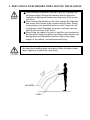
1 . PRECAUTIONS TO BE HEEDED FOR OPERATION
In order to prevent accidents, be sure to comply with the following points before and during operation.
PRECAUTIONS TO BE HEEDED FOR OPERATION BEFORE STARTING THE OPERATION
In order to avoid accidents, check the following before starting the operation:
Check if all of the adjusters are in contact with the surface. If they are not,
the cabinet can move and cause an accident.
Do not climb on the product. Climbing on the product can cause falling
down accidents. To check the top portion of the product, use a step.
To avoid electric shock, check to see if door & cover parts are Locked.
To avoid electric shock, short circuit and or parts damage, do not put the
following items on or in the periphery of the product:
Flower vases, flower pots, cups, water tanks, cosmetics, and receptacles/
containers/vessels containing chemicals and water.
To avoid injury, be sure to provide sufficient space by considering the
potentially crowded situation at the installation location. Insufficient installation space can cause the player to come into contact with or hit others
and result in injury or trouble.
PRECAUTIONS TO BE HEEDED DURING OPERATION
To avoid injury and accidents, those who fall under the following catagories are not
allowed to play the game:
* Intoxidated persons.
* Those who have high blood pressure or heart problems.
* Those who have experienced muscle convulsion or loss of consciousness when
playing video games, etc.
* Persons susceptible to motion sickness.
* Persons whose acts runs counter to the products warning displays.
To avoid electric shock and short circuit, do not allow customers to put hands and
fingers or extraneous matter in openings of the product or small openings in or
around doors.
To avoid falling down and injury resulting from falling down, immediatly stop the
customer’s leaning against or climbing on the product, etc.
To avoid electric shock and short circuit, do not allow the customers to unplug the
power plug without a justifiable reason.
4
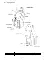
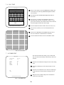
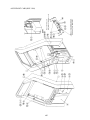
2 . NAME OF PARTS
GAME SPECIFICATIONS
WIDTH
LENGTH
HEIGHT
WEIGHT
All measurements are in inches
WHEN ASSEMBLED
30”
X
37”
5
X
65”
223 LBS.
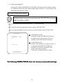
3 . ACCESSORIES
6
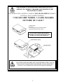
THE SHIPMENT METHOD DESCRIBED BELOW ONLY
APPLIES TO ‘MODEL 3’ BOARDS CONTAINED IN THE
FOLLOWING GAMES:
LOST WORLD, VIRTUA FIGHTER 3, SUPER GT, SEGA BASS FISHING, STRIKER 2,
DAYTONA 2, RALLY, HARELY DAVIDSON
!!NEVER SHIP MODEL 3 GAME BOARDS
OUTSIDE OF CAGE!!
CARTON BOX
601-8928 (1)
Used for transporting the GAME BOARD.
{SUPPLIED WITH YOUR GAME}
DO NOT SHIP GAME BOARD WITHOUT
THIS BOX AS IT MAY DAMAGE THE GAME
BOARD AND VOID YOUR WARRANTY.
“CHECK SIDE” Display
FILTER BOARD
NO OTHER GAMES BOARDS ARE TO BE SHIPPED IN THE CAGE AS
THEY MAY BE DAMAGED BEYOND REPAIR. PLEASE SHIP THEM
WITHOUT CAGE PROPERLY PROTECTED DURING SHIPPING.
7
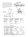
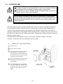
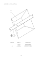
4 . ASSEMBLING AND INSTALLATION
Assembling should be performed as per this manual. Since this is a
complex machine, erroneous assembling may cause damage to the
machine, or malfunctioning to occur.
When assembling, be sure to perform work by plural persons.
Depending on the assembly work, there are some cases in which
performing the work by a single person can cause personal injury or
parts damage.
When carrying out the assembly work, follow the procedure in the following 4-item sequence:
1
SECURING IN PLACE (ADJUSTER ADJUSTMENT)
2
POWER SUPPLY
3
TURNING POWER ON
4
ASSEMBLING CHECK
Note that the tools such as a phillips screwdriver and wrench for M16 hexagon bolt w/24 mm width
across flats are required for the assembly work.
8
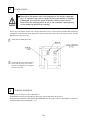
1
SECURING IN PLACE (ADJUSTER ADJUSTMENT)
Be sure to have all the Adjusters make contact with the surface. Unless the Adjusters come into contact with the surface, the Cabinet
can move of itself, causing an accident.
This machine has 2 each of casters and adjusters (shown below). When the installation position is determined, cause
the adjusters to come into contact with the floor directly, make adjustments in a manner so that the casters will be
raised approximately 5mm. from the floor and make sure that the machine position is level.
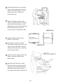
1
Move the machine to the installation position.
2
Cause all of the leg adjusters to make contact
with the floor. By using a wrench, make
adjustments in the height of the leg adjusters to
ensure that the machine's position is level.
3
After making adjustments, fasten the leg
adjuster nut upward and secure the height of the
leg adjuster.
4
BOTTOM VIEW
Depending on the floor surface status of the installation location, the Rear Cabinet may move of itself. As
shown, the NON-SLIP SHEET is attached to the back side of the CAUTION MAT. Ensure that the Adjuster is
installed in the manner to match the position of NON-SLIP SHEET
5
After making adjustments, fasten the adjuster nut upwards and secure the height of the adjuster
FASTEN UPWARDS
1/4” INCH
LEG ADJUSTER
9
2
POWER SUPPLY
Ensure that the power cord is not exposed on the surface (passage,
etc.). If exposed, they can be caught and are susceptible to damage.
If damaged, the cord can cause an electric shock or short circuit.
Ensure that the wiring position is not in the customer's passage way
or the wiring has protective covering.
The AC unit is mounted on the left side of Front Cabinet DX. The AC Unit incorporates the Main SW, Earth Terminal and Inlet. Firmly insert the Power Plug into the Socket Outlet and the other side of the plug to the Inlet. Turn the
Main SW ON to turn power ON.
1
Ensure that the Main SW is OFF.
2
Connect the Power cord to the Outlet
Socket. Ensure power cord is not in
customer’s passage way or wiring has
protective covering.
3
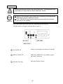
TURNING POWER ON
To turn power on, turn the AC Unit’s Main SW on.
The Billboard’s Fluorescent Lamp lights up and images will be outputted on the projector.
Background music (BGM) is outputted during ADVERTISE from the speaker. However, this BGM is not emitted if
“No BGM output during ADVERTISE” is set.
10
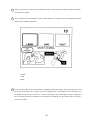
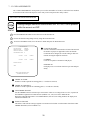
4
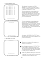
ASSEMBLING CHECK
The TEST MENU allows for each part of the cabinet to be checked, the Monitor to be adjusted, and the coin and
game related various functions to be performed.
CPU ROM TEST
GOOD
GOOD
GOOD
GOOD
GOOD
GOOD
GOOD
GOOD
GOOD
GOOD
GOOD
GOOD
GOOD
GOOD
GOOD
GOOD
GOOD
GOOD
GOOD
GOOD
(CROM03 BANK)
(CROM02 BANK)
(CROM01 BANK)
(CROM00 BANK)
(CROM13 BANK)
(CROM12 BANK)
(CROM11 BANK)
(CROM10 BANK)
(CROM23 BANK)
(CROM22 BANK)
(CROM21 BANK)
(CROM20 BANK)
(CROM33 BANK)
(CROM32 BANK)
(CROM31 BANK)
(CROM30 BANK)
(CROM3)
(CROM2)
(CROM1)
(CROM0)
IC.1
IC.2
IC.3
IC.4
IC.5
IC.6
IC.7
IC.8
IC.9
IC.10
IC.11
IC.12
IC.13
IC.14
IC.15
IC.16
IC.17
IC.18
IC.19
IC.20
*****
*****
*****
*****
*****
*****
*****
*****
*****
*****
*****
*****
*****
*****
*****
*****
*****
*****
*****
*****
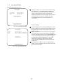
Selecting the MEMORY TEST on the test mode menu screen
causes the on-board memory to be tested automatically. The
game board is satisfactory if the display beside each IC No.
shows GOOD.
PRESS TEST BUTTON TO EXIT
INPUT TEST
CAST
SELECT
COIN
SERVICE
TEST
OFF
OFF
OFF
OFF
OFF
ROD X
ROD Y
REEL SPEED
STICK X
STICK Y
80H
80H
80H
80H
80H
Selecting the INPUT TEST on the menu screen in the test
mode to display the screen on which each SW and Volume is
tested. Press each switch. (To check the Coin SW, insert a
Coin from the inlet with the Coin Chute Door being opened.)
If the display beside each switch is ON, the switch and wiring
connection are satisfactory. Check the display of each Volume
value. The Volume could have an irregularity caused by
differences between machines and vibration during transportation. Set the Volume values by referring to Section ?
PRESS TEST BUTTON TO EXIT
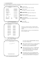
OUTPUT TEST
>AC MOTOR
CLUTCH
REEL BREAK
OFF
OFF
OFF
EXIT
In the output test mode, carry out lamp test to ascertain that
each lamp lights up satisfactorily.
SELECT WITH SERVICE BUTTON AND
PRESS TEST BUTTON TO EXIT
11
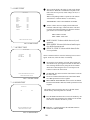
SOUND TEST
NO
:
(0)
In the TEST mode, selecting SOUND TEST causes the
screen, on which sound related BD and wiring connections are tested, to be displayed. be sure to check if the
sound is satisfactorily emitted from each of speaker and
the sound volume is appropriate.
SELECT WITH SERVICE BUTTON
PRESS TEST BUTTON TO EXIT
C.R.T. TEST 1/2
123456789012345678901234567890121234567890123
123456789012345678901234567890121234567890123
123456789012345678901234567890121234567890123
123456789012345678901234567890121234567890123
123456789012345678901234567890121234567890123
123456789012345678901234567890121234567890123
123456789012345678901234567890121234567890123
123456789012345678901234567890121234567890123
123456789012345678901234567890121234567890123
RED
123456789012345678901234567890121234567890123
123456789012345678901234567890121234567
123456789012345678901234567890121234567890123
123456789012345678901234567890121234567
123456789012345678901234567890121234567
123456789012345678901234567890121234567
123456789012345678901234567890121234567
123456789012345678901234567890121234567
123456789012345678901234567890121234567
GREEN
123456789012345678901234567890121234567
123456789012345678901234567890121234567
123456789012345678901234567890121234567
123456789012345678901234567890121234567
12345678901234567890123456789
12345678901234567890123456789
12345678901234567890123456789
12345678901234567890123456789
BLUE
12345678901234567890123456789
12345678901234567890123456789
12345678901234567890123456789
12345678901234567890123456789
In the TEST mode menu, selecting C.R.T. TEST allows the
screen (on which the projector is tested) to be displayed.
Although the projector adjustments have been made at the
same time of shipment from the factory, color deviation,
etc., may occur due to the effect caused by geomagnitism,
the location building’s steel frames and other game machines in the periphery. By watching the test mode screen,
make judgement as to whether an adjustment is needed. If it
is neccessary, adjust the projector by refering to Section 9.
WHITE
PRESS TEST BUTTON TO CONTINUE
1234567890123456789012345678
1234567890123456789012345678
1234567890123456789012345678
1234567890123456789012345678
1234567890123456789012345678
1234567890123456789012345678
1234567890123456789012345678
1234567890123456789012345678
1234567890123456789012345678
1234567890123456789012345678
1234567890123456789012345678
1234567890123456789012345678
1234567890123456789012345678
1234567890123456789012345678
1234567890123456789012345678
1234567890123456789012345678
1234567890123456789012345678
1234567890123456789012345678
1234567890123456789012345678
1234567890123456789012345678
1234567890123456789012345678
1234567890123456789012345678
1234567890123456789012345678
1234567890123456789012345678
1234567890123456789012345678
C.R.T. TEST 2/2
PRESS TEST BUTTON TO CONTINUE
Perform the above inspections also at the time of monthly inspection.
12
5 . PRECATIONS TO BE HEEDED WHEN MOVING THE MACHINE
When moving the machine, be sure to pull out the plug from
the power supply. Moving the machine with the plug as is
inserted can damage the power cord and cause a fire or electric shock.
When moving the machine on the floor, retract the Adjusters
and ensure that Casters make contact with the floor. During
transportation, pay careful attention so that Casters do not
tread power cords. Damaging the power cords can cause an
electric shock and/or short circuit.
When lifting the cabinet, be sure to hold the catch portions or
bottom part. Lifting the cabinet by holding other portions can
damage parts and installation portions, due to the empty
weight of the cabinet, and cause personal injury.
Use care when handling glass made parts. When the glass is damaged, fragments of glass can cause injury
13
6 . CONTENTS OF GAME
The following are operations and responses obtained when the machine functions satisfactorily. Any functioning
different from the following may have been caused by a certain fault. Immediately investigate and eliminate the
cause of malfunctioning to ensure satisfactory operation.
HOW TO PLAY
The ADVERTISE mode appearing on the screen before game play is comprised of the following:
In this game, satisfying the condition of “CLEAR WEIGHT” (the total weight of bass fished up) preset for each area
within the time limit results in a STAGE CLEAR. If you continue when the time is up, however, the current total
weight will remain effective. Clearing all of the Areas allows you to proceed to the Special Stage where huge bass
reside. The player who fishes up big bass can rank among the BIG BASS RANKING players by entering his name.
This game employs an exclusively used Special Controller inclusive of the Game Start Button.
14
1
Insert a coin(s). Up to 9 credits can be counted at one time. Coins inserted after counting 9 credits will neither
be counted nor returned.
2
Select a Fishing area from among the 3 Areas of Lake Paradise (a virtual lake). Choose with SELECT LEVER
and decide by START/CAST button.
LODGE
CAPE
INLET
3 Then, select the LURE. Select with the SELECT LEVER and decide by START/CAST button. Each type of lure
has specific characteristics (for example, some may be appropriate for a certain depth of water while others may
be suitable for a specific action, time zone, or status of desired bass). By considering these factors, using lures in
the most efficient manner will contribute to increasing the bass fishing-up rate. The characteristics of each type
of lure are as follows:
15
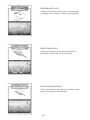
SPINNER BAIT (EASY)
Attract bass with this bait while reeling at a constant speed,
or stopping to reel sometimes to allow for blade glistening.
DEEP CRANK (EASY)
This type is used for deep water. Have the lure hit the
bottom and reel, then repeat real and stop action.
SHALLOW CRANK (EASY)
This is used for shallow water. Have the lure hit the bottom
and reel, then repat reel and stop motion.
16
VIBRATION (EASY)
Attract bass by reeling at the constant speed or having the
lure hit an obstacle such as a stone, driftwood, etc. to cause
irregular movements.
MINNOW/ JERK BAIT (NORMAL)
Attract bass by reeling at a constant speed and jerking the
rod to reel so that the lure will look like a small fish
making a quick escape.
PENCIL BAIT (DIFFICULT)
Attract bass to the water surface by reeling the rod while
repeating the slightly twitching motion to have the lure
look like a smalll fish of insects writhing on the surface.
17
Try to master the best lure and the most appropriate action to catch a big fish.
18
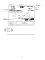
4
After the lure is decided, set the CAST spot (where to cast the lure). Select with the SELECT
LEVER and decide by START/CAST button. Press the START/CAST button to have the lure
cast automatically (at this time the player does not have to do the cast movement).
Having its own territory, a big fish is hiding at a certain point in each area depending on the time
zone and water temperatures. Cast in various points and find where the big one is.
19
5
When the lure hits the surface, turn the reel handle, move the rod, and activate the lure to
attract bass.
When bass snaps at the lure, pull the rod towards you by hooking up.
For timely hooking.........FISH! is displayed.
For untimely hooking.....MISS! is displayed.
For a successful hooking, HIT BONUS time is added depending on the size of the hit bass.
20
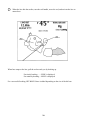
6
When the bass is hooked, pull it towards you by paying attention to LINE TENSION METER.
21
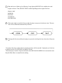
7
When the bass is fished up, the following 5-step display &WEIGHT to be added to the total
weight are shown. Then, BONUS TIME is added depending on the weight of the bass.
SMALL ONE
MEDIUM
BIG ONE
SUPER BIG
RECORD SIZE
8
If the total wieght exceeds the Norm weight, the player can proceed to the next Area. The next
Area will be determined automatically as shown.
9
Clearing all of the Areas allows the player to proceed to the Special Area where lots of big ones
are.
* Everytime the player catches 4 basses, the Special Lure will be awarded. Continued use of the lure
is allowed in cases of CONTINUE and AREA CLEAR.
* When the player catches a big bass and ranks in the BIG BASS RANKING, he can enter his name.
Only the Black Bass is counted for the ranking.
22
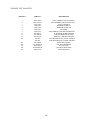
7 . EXPLANATION OF TEST AND DATA DISPLAY
By operating the switch unit, periodically perform the tests and data check. When installing
the machine initially or collecting cash, or when the machine does not function correctly,
perform checking in accordance with the explanations given in this section. The following
shows tests and modes that should be utilized as applicable.
TABLE 7
EXPLANATION OF TEST MODE
ITEMS
DESCRIPTION
SECTIONS
When the machine is installed, perform the following:
INSTALLATION 1. Check to see that each setting is as per standard setting made
at the time of shipment.
OF MACHINE
MEMORY
PERIODIC
SERVICING
7 - 9, 7 - 10
2. In the INPUT TEST mode, check each SW and VR.
7-5
3. In the OUTPUT TEST mode, check each of lamps.
7-6
4. In the MEMORY TEST mode, check ICs on the IC Board.
7 - 3, 7 - 4
Choose MEMORY TEST in the MENU mode to allow the
MEMORY test to be performed. In this test, PROGRAM
RAMs, ROMs, and ICs on the IC Board are checked.
Periodically perform the following:
1. MEMORY TEST
7 - 3, 7 - 4
2. Ascertain each setting.
7 - 9, 7 - l0
3. In the INPUT TEST mode, test the CONTROL device
7-5
4. In the OUTPUT TEST mode, check each of lamps.
7-6
1. In the INPUT TEST mode, check each SW and VR.
7-5
2. Adjust or replace each SW and VR.
8
3.If the problem can not be solved yet, check the CONTROL’s moves.
8
PROJECTOR
In the PROJECTOR ADJUSTMENT mode, check to see if the
PROJECTOR adjustment is appropriately made.
7-8
IC BOARD
1. MEMORY TEST
CONTROL
SYSTEM
DATA CHECK
2. In the SOUND TEST mode, check the sound related ROMs.
7-7
Check such data as game play time and histogram to adjust the
difficulty level, etc
7 - 12
23
7 - 1 COIN METER, INTERNAL SWITCHES, AND SWITCH UNIT
COIN METER
If the COIN METER and the Game Board are electronically disconnected, game play is not possible.
Do not touch places other than those specified. Touching places
other than those specified can cause an electric shock or short
circuit accident.
The Coin Meter is in the CASHBOX door.
INTERNAL SWITCHES
The Control Panel Base can be opened by unlocking the backside lock.
24
SWITCH UNIT
Never touch places other than those specified. Touching places not
specified can cause electric shock and short circuit.
Adjust to the optimum sound volume by considering the environmental
requirements of the installation location.
If the COIN METER and the game board are electrically disconnected,
game play is not possible.
The Control Panel Base can be opened by unlocking the backside lock.
Internal switches will appear when the Base is opened
1 TEST SWITCH
Allows for entering the Test Mode of Game BD.
2 SERVICE SWITCH
SERVICE CREDIT SW. Used without registering on the Coin Meter.
3 SOUND VOLUME
Adjust the Speaker Volume.
25
DOOR SWITCH
When the service door is removed, the door switch functions to turn power off automatically. To turn
power on the with the service door as is removed, use the accessory Cheater as per the (1)-(2) procedure below.
26
7 - 2 TEST MODE
This mainly checks if the operation of the game BD is accurate, and allows for COIN
ASSIGNMENTS/GAME ASSIGNMENTS setting and Projector adjustments.
TEST MENU
CPU MEMORY TEST
1
Push the TEST BUTTON to cause the following TEST MENU to appear:
2
By pushing the SERVICE BUTTON, bring the
“>” mark to the desired item and press the
TEST BUTTON. This will select the item’s
test.
3
After the test is complete, move the “>” mark
to “EXIT” and press the TEST BUTTON to
return to game mode.
VIDEO MEMORYTEST
BOUNDRY SCAN TEST
INPUT TEST
OUTPUT TEST
SOUND TEST
C.R.T.
TIMER TEST
GAME ASSIGNMENTS
COIN ASSIGNMNETS
VOLUME SETTING
BOOKKEEPING
BACKUP DATA CLEAR
>EXIT
SELECT WITH SERVICE BUTTON
AND PRESS TEST BUTTON
FIG. 7.2 TEST MENU
7 - 3 MEMORY TEST
The MEMORY TEST mode is for checking the
on-BD memeory IC functioning.
“GOOD” is displayed for normal ICs and “BAD”
is displayed for abnormal ICs
CPU ROM TEST
GOOD
GOOD
GOOD
GOOD
GOOD
GOOD
GOOD
GOOD
GOOD
GOOD
GOOD
GOOD
GOOD
GOOD
GOOD
GOOD
GOOD
GOOD
GOOD
GOOD
(CROM03 BANK)
(CROM02 BANK)
(CROM01 BANK)
(CROM00 BANK)
(CROM13 BANK)
(CROM12 BANK)
(CROM11 BANK)
(CROM10 BANK)
(CROM23 BANK)
(CROM22 BANK)
(CROM21 BANK)
(CROM20 BANK)
(CROM33 BANK)
(CROM32 BANK)
(CROM31 BANK)
(CROM30 BANK)
(CROM3)
(CROM2)
(CROM1)
(CROM0)
IC.1
IC.2
IC.3
IC.4
IC.5
IC.6
IC.7
IC.8
IC.9
IC.10
IC.11
IC.12
IC.13
IC.14
IC.15
IC.16
IC.17
IC.18
IC.19
IC.20
*****
*****
*****
*****
*****
*****
*****
*****
*****
*****
*****
*****
*****
*****
*****
*****
*****
*****
*****
*****
This test starts immediately after selection from
the menu in the test mode. When in execution, the
“TESTING NOW” message will be displayed at
the lower part to the screen. Press the Test Button
to proceed to CPU RAM TEST
PRESS TEST BUTTON TO EXIT
FIG. 7.3a MEMORY TEST
CPU ROM TEST
GOOD
GOOD
GOOD
GOOD
(SDRAM)
(BACK UP SRAM)
(SDRAM)
(SDRAM)
IC. 13
IC. 21
IC. 94 or IC.19
IC. 17
IC. 15
IC. 22
IC. 20
IC. 18
Test starts immediately after proceeding to this
mode from CPU ROM TEST. During execution,
the “TESTING NOW” message will be displayed
at the lower part of the screen. When an error
occurs, the ERROR message is shown. After
finising the test, press the TEST button to return
to the menu mode.
PRESS TEST BUTTON TO EXIT
FIG. 7.3b MEMORY TEST
27
7 - 4 VIDEO MEMORY TEST
VIDEO BOARD ROM TEST
GOOD
GOOD
GOOD
GOOD
GOOD
GOOD
GOOD
GOOD
GOOD
GOOD
GOOD
GOOD
GOOD
GOOD
GOOD
GOOD
(VROM01)
(CROM00)
(CROM03)
(CROM02)
(CROM05)
(CROM04)
(CROM07)
(CROM08)
(CROM11)
(CROM10)
(CROM13)
(CROM12)
(CROM15)
(CROM14)
(CROM17)
(CROM16)
IC.26
IC.27
IC.28
IC.29
IC.30
IC.31
IC.32
IC.33
IC.34
IC.35
IC.36
IC.37
IC.38
IC.39
IC.40
IC.41
*****
*****
*****
*****
*****
*****
*****
*****
*****
*****
*****
*****
*****
*****
*****
*****
This allows the functioning of the VIDEO
MEMORY IC’s on the IC board to be checked.
“GOOD” is displayed for normal IC’s and “BAD”
is displayed for abnormal IC’s if any.
Test starts immediately after proceeding to this
mode from the menu in the test mode. During
execution, the “TESTING NOW” message will be
didplayed at the lower portion of the screen. After
fininshing the test, press the TEST BUTTON to
proceed to VIDEO RAM.
PRESS TEST BUTTON TO CONTINUE
FIG. 7.4a VIDEO MEMORY TEST
VIDEO BOARD RAM TEST
PRESS TEST BUTTON TO CONTINUE
FIG. 7.4b VIDEO MEMORY TEST
Test starts immediately after proceeding to this
mode from the VIDEO BOARD ROM TEST.
During execution, the “TESTING NOW” message
will be displayed at the lower portion of the screen.
If staus is satisfactory, nothing will be displayed.
After fininshing the test, press the TEST BUTTON
to return to the menu mode.
Selecting the “BOUNDRY SCAN TEST” causes
the Game board’s testing in terms of hardware to be
performed automatically.
7 - 5 BOUNDRY SCAN TEST
BOUNDRY SCAN TEST
When the test is completed, if the results are as
shown left, it is satisfacory.
After finishing the test, press the TEST BUTTON
to have the MENU MODE return on the screen.
Next, turn power off and then turn it back on again.
To avoid malfunctioning, have the Board intialized
by turning the power off and then on.
PRESS TEST BUTTON TO EXIT
FIG. 7.5 BOUNDRY SCAN TEST
If there is any hardware problems, an error message
is displayed. Please contact the offices herein stated
or where the product was purchased from.
28
7 - 6 INPUT TEST
This test mode displays the status of each switch, button,
and Volu me. When the switch/button corrsponds to the
name of the item is pressed, if OFF changes to ON, it is
satisfactory.
When corresponding Volume is operated, if the Volume
value differs in a natural manner, it is satisfactory.
INPUT TEST
CAST
SELECT
COIN
SERVICE
TEST
OFF
OFF
OFF
OFF
OFF
ROD X
ROD Y
REEL SPEED
STICK X
STICK Y
80H
80H
80H
80H
80H
APPROPRIATE VALUE OF TENSION VOLUME
Tension volume values are displayed in hexadecimal
numerals within the range of 00H~ffH. If the value does
not satisfy the following limitations, adjust the Volumes
gear mesh so as to meet the requiremnts.
MIN. LIMIT: Over20H
MAX. LIMIT: Under e0H
PRESS TEST BUTTON TO EXIT
FIG. 7.6 INPUT TEST
7 - 7 OUTPUT TEST
OUTPUT TEST
>AC MOTOR
CLUTCH
REEL BREAK
OFF
OFF
OFF
ROD X, ROD Y: Volumes which detect reel (rod)
operation.
REEL SPEED: Volume which detects handle operation. 80H when not turned.
STICK X, STICK Y: Volume which detects Select
Lever operation.
Choose OUTPUT TEST to cause the following lower screen to
appear. In this test, check the status of each lamp.
EXIT
By using the Service Button, select the desired item and
execute the test by pressing the test button to shift OFF to
ON. Selecting another item by using the Service Button
shifts ON to OFF. Bring the arrow to exit and press test
button to return to the menu mode.
SELECT WITH SERVICE BUTTON AND
PRESS TEST BUTTON TO EXIT
FIG. 7.7 OUTPUT TEST
7 - 8 SOUND TEST
AC MOTOR: The motor inside the Control Panel. with ON
the motor rotates.
CLUTCH: Clutch mechanism inside Control Panel. With
ON, GRIP operation becomes weightier.
REEL BREAK: REEL BRAKE which is in the mechanism
inside the Reel Handle. With ON, handle operation becomes
weightier.
SOUND TEST
NO
:
000
This enables sound used in the game to be checked. Sound
related memory and each speaker are checked.
Press the SERVICE BUTTON to increse the number by one
and the sound corresponding to the number will be emitted.
Note that No. 000 does not emit any sound.
SELECT WITH SERVICE BUTTON
PRESS TEST BUTTON TO EXIT
Bring the “>” to EXIT and press the TEST BUTTON to
return to the MENU MODE.
FIG. 7.8 SOUND TEST
29
7 - 9 C.R.T. TEST
C.R.T. TEST 1/2
12345678901234567890123456789012123456789012
12345678901234567890123456789012123456789012
12345678901234567890123456789012123456789012
12345678901234567890123456789012123456789012
12345678901234567890123456789012123456789012
12345678901234567890123456789012123456789012
12345678901234567890123456789012123456789012
12345678901234567890123456789012123456789012
12345678901234567890123456789012123456789012
12345678901234567890123456789012123456789012
RED
12345678901234567890123456789012123456789012
123456789012345678901234567890121234567
123456789012345678901234567890121234567
123456789012345678901234567890121234567
123456789012345678901234567890121234567
123456789012345678901234567890121234567
123456789012345678901234567890121234567
123456789012345678901234567890121234567
GREEN
123456789012345678901234567890121234567
123456789012345678901234567890121234567
123456789012345678901234567890121234567
123456789012345678901234567890121234567
1234567890123456789012345678
1234567890123456789012345678
1234567890123456789012345678
1234567890123456789012345678
1234567890123456789012345678
BLUE
1234567890123456789012345678
1234567890123456789012345678
1234567890123456789012345678
WHITE
PRESS TEST BUTTON TO CONTINUE
1234567890123456789012345678
1234567890123456789012345678
1234567890123456789012345678
1234567890123456789012345678
1234567890123456789012345678
1234567890123456789012345678
1234567890123456789012345678
1234567890123456789012345678
1234567890123456789012345678
1234567890123456789012345678
1234567890123456789012345678
1234567890123456789012345678
1234567890123456789012345678
1234567890123456789012345678
1234567890123456789012345678
1234567890123456789012345678
1234567890123456789012345678
1234567890123456789012345678
1234567890123456789012345678
1234567890123456789012345678
1234567890123456789012345678
1234567890123456789012345678
1234567890123456789012345678
1234567890123456789012345678
1234567890123456789012345678
Select C.R.T. TEST to cause the MONITOR to display the
screen shown left, allowing MONITOR adjustment status
to be checked.
Periodically check the MONITOR adjustment status on
this screen.
The screen (1/2) enables color adjustment check to be
performed. The color bar of each of the 4 colors, i.e.,red,
green, blue, and white, is the darkest at the extreme left and
becomes brighter towards the extreme right.
Press the TEST BUTTON to shift to the next screen (2/2).
The screen (2/2) allows screen size and distortion to be
tested.
C.R.T. TEST 2/2
Check if the CROSSHATCH FRAME LINE goes out of
the screen and if the crosshatch lines are distorted.
Press the TEST BUTTON to return to the MENU mode.
PRESS TEST BUTTON TO EXIT
FIG. 7.9 C.R.T. TEST
7 - 10 TIMER TEST
This test mode allows the setting of year, month, and
day, as well as built-in battery, and real time clock to be
checked.
TIMER TEST
1997, 10/31 (FRI)
BATTERY
00 : 00 : 00
O.K.
YEAR
MONTH
DAY
HOUR
MINUTE
SECOND
1997
10
31
00
00
00
Press the Service Button to bring the arrow to the setting
item.
Press the Test Button to set the desired value for each
item.
Press the Service Button to move the arrow and bring it
to SET, then press the test button to change to the set
value.
SET
>EXIT
Bring the arrow to EXIT and press the test button to
return to the menu mode.
PRESS TEST BUTTON TO EXIT
FIG. 7.10 TIMER TEST
30
7 - 11 GAME ASSIGNMENTS
Selecting the GAME ASSIGNMENTS in the MENU mode causes the present game settings
to be displayed and also the game settings changes (game difficulty, etc.) can be made. Each
item displays the following content.
SETTING CHANGE PROCEDURE
Setting changes cannot be stored unless the TEST BUTTON is pressed
while the arrow is on EXIT.
1
Press the SERVICE BUTTON to move the “>” to the desired item.
2
Choose the desired setting change item by using the TEST BUTTON.
3
To return to the MENU mode, move the arrow to EXIT and press the TEST BUTTON.
GAME ASSIGNMENTS
ADVERTISE SOUND
GAME DIFFICULTY
ON
NORMAL
>EXIT
COUNTRY TYPE: ****
ADVERTISE SOUND
Determines wether ADVERTISE SOUND is to
be emitted or not by the setting to ON when
emitting it and to OFF when not emitting it.
GAME DIFFICULTY
Sets the Game Difficulty in 5 catagories from 1 to
8. The greater the number is, the higher the
difficulty level becomes. Alternately it may
display each catagory by name;
Very Easy, Easy, Normal, Hard, Very Hard
SELECT WITH SERVICE BUTTON
AND PRESS TEST BUTTTON
The Following FIGURES/TABLES show the factory recommended settings.
31
7 - 12 COIN ASSIGNMENTS
The “COIN ASSIGNMENTS” mode permits you to set the start number of credits, as well as the basic numbers
of coins and credits. This mode expresses “how many coins correspond to how many credits.”
SETTING CHANGE PROCEDURE
Setting changes cannot be stored unless the TEST BUTTON is pressed
while the arrow is on EXIT.
1
Press the SERVICE BUTTON to move the arrow to the desired item.
2
Choose the desired setting change item by using the TEST BUTTON.
3
To return to the MENU mode, move the arrow to EXIT and press the TEST BUTTON.
COIN ASSIGNMENTS
COIN CHUTE TYPE
CREDIT TO START
CREDIT TO CONTINUE
COMMON
2 CREDITS
1 CREDIT
COIN/CREDIT SETTING
#1
CHUTE#1
1 COIN
1 CREDIT
CHUTE#2
1 COIN
1 CREDIT
COIN CHUTE TYPE
Sets the combination of the number of COIN CHUTEs and
the number of players as applicable. In the case that the
COIN CHUTE is changed, be sure the setting is made in a
manner meeting the replaced coin chute.
COMMON:
Coins are accepted in common for both players.
MANUAL SETTING
>EXIT
INDIVIDUAL:
Each player uses a coin chute which accepts coins independently.
SELECT WITH SERVICE BUTTON
AND PRESS TEST BUTTON
CREDIT TO START
Number of credits required for starting game (1~5 credits are selected.)
CREDIT TO CONTINUE
Number of credits required for continuing game (1~5 credits are selected.)
COIN/CREDIT SETTING
Sets the CREDITS increase increment per coin insertion. There are 27 setings from #1 to #27, expressed in
XX CREDIT as against XX COINS inserted. (TABLE 7.9a, 7.9b) #27 refers to FREE PLAY.
When the COIN CHUTE TYPE is set to INDIVIDUAL, there are some setting numbers not displayed as
indicated in TABLE 7.9b.
MANUAL SETTING
This allows credit increase setting as against coin insertion to be further set in the manner finer than COIN/
CREDIT SETTING (refer to TABLE 7.9c).
32
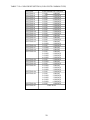
TABLE 7.12a COIN/CREDIT SETTING (COIN CHUTE COMMON TYPE)
SETTING
SETTING #1
SETTING #2
SETTING #3
SETTING #4
SETTING #5
SETTING #6
SETTING #7
SETTING #8
SETTING #9
SETTING #10
SETTING #11
SETTING #12
SETTING #13
SETTING #14
SETTING #15
SETTING #16
SETTING #17
SETTING #18
SETTING #19
SETTING #20
SETTING #21
SETTING #22
SETTING #23
SETTING #24
SETTING #25
SETTING #26
SETTING #27
FUNCTIONING OF CHUTE#1
1 COIN
1 CREDIT
1 COIN
2 CREDITS
1 COIN
3 CREDITS
1 COIN
4 CREDITS
1 COIN
5 CREDITS
1 COIN
2 CREDITS
1 COIN
5 CREDITS
1 COIN
3 CREDITS
1 COIN
4 CREDITS
1 COIN
5 CREDITS
1 COIN
6 CREDITS
2 COINS
1 CREDIT
1 COIN
1 CREDIT
1 COIN
2 CREDITS
1 COIN
1 CREDIT
2 COINS
3 CREDITS
1 COIN
3 CREDITS
3 COINS
1 CREDIT
4 COINS
1 CREDIT
1 COIN
1 CREDIT
2 COINS
2 CREDITS
3 COINS
3 CREDITS
4 COINS
5 CREDITS
1 COIN
5 CREDITS
5 COINS
1 CREDIT
1 COIN
2 CREDITS
2 COINS
1 CREDIT
4 COINS
2 CREDITS
5 COINS
3 CREDITS
1 COIN
3 CREDITS
1 COIN
1 CREDIT
2 COINS
2 CREDITS
3 COINS
3 CREDITS
4 COINS
4 CREDITS
5 COINS
6 CREDITS
1 COIN
1 CREDITS
FREE PLAY
33
MANUAL SETTING
Selecting MANUAL SETTING in the COIN ASSIGNMENTS mode displays the following screen.
MANUAL SETTING
COIN TO CREDIT
1 COIN
BONUS ADDER
NO BONUS ADDER
1
1 CREDIT
2
COIN CHUTE #1 MULTIPLIER
1 COIN COUNTS AS 1 COIN
COIN
1
2
3
CREDIT 1
2
3
4
4
5
5
6
6
7
7
8
8
9
9
COIN CHUTE #2 MULTIPLIER
1 COIN COUNTS AS 1 COIN
COIN
1
2
3
CREDIT 1
2
3
4
4
5
5
6
6
7
7
8
8
9
9
3
>EXIT
SELECT WITH SERVICE BUTTON
AND PRESS TEST BUTTON
FIG. 7.12b MANUAL SETTING
1 Determines Coin/Credit setting.
2 This sets how many coins should be inserted to obtain one Service Coin.
3 This sets how many tokens one coin represents.
Table 7.12c MANUAL SETTING
COIN TO CREDIT
1 COIN
2 COINS
3 COINS
4 COINS
5 COINS
6 COINS
7 COINS
8 COINS
9 COINS
BONUS ADDER
NO BONUS ADDER
2 COINS GIVE 1 EXTRA COIN
3 COINS GIVE 1 EXTRA COIN
4 COINS GIVE 1 EXTRA COIN
5 COINS GIVE 1 EXTRA COIN
6 COINS GIVE 1 EXTRA COIN
7 COINS GIVE 1 EXTRA COIN
8 COINS GIVE 1 EXTRA COIN
9 COINS GIVE 1 EXTRA COIN
COIN CHUTE MULTIPLIER
1 COIN COUNTS AS 1 COIN
1 COIN COUNTS AS 2 COINS
1 COIN COUNTS AS 3 COINS
1 COIN COUNTS AS 4 COINS
1 COIN COUNTS AS 5 COINS
1 COIN COUNTS AS 6 COINS
1 COIN COUNTS AS 7 COINS
1 COIN COUNTS AS 8 COINS
1 COIN COUNTS AS 9 COINS
34
1 CREDIT
1 CREDIT
1 CREDIT
1 CREDIT
1 CREDIT
1 CREDIT
1 CREDIT
1 CREDIT
1 CREDIT
7 - 13 VOLUME SETTING
This allows Slide Volume to be set.
VOLUME SETTING
AUTO SETTING
PULL POSITION
SWING POSITION
REEL
MAX dd (df) MIN 74 (75)
MAX 98 (95) MIN 07 (03)
NEUTRAL 88 (88)
>CONTINUE WITH SAVE
CONTINUE WITHOUT SAVE
SELECT WITH SERVICE BUTTON
AND PRESS TEST BUTTON
Fig. 7.13a VOLUME SETTING
VOLUME SETTING
MANUAL SETTING
TENSION
STICK X
STICK Y
MAX da (de) MIN 07 (06)
MAX ao (aB) MIN 61 (62) NEUTRAL 82 (83)
MAX af (a1) MIN 66 (63) NEUTRAL 84 (84)
>EXIT WITH SAVE
EXIT WITHOUT SAVE
SELECT WITH SERVICE BUTTON
AND PRESS TEST BUTTON
Settings of volumes, etc., can be executed. Volume setting
has 2 catagories, i.e., AUTO SETTING and MANUAL
SETTING. AUTO SETTING performs the setting of the
Volume of the portions that can be set automatically.
MANUAL SETTING executes the setting of the Volume of
the portions that can only be set manually. Selecting
VOLUME SETTING causes AUTO SETTING to be
executed first.
AUTO SETTING
AUTO SETTING starts of itself. By holding the rod, when
the line is pulled, move the rod forward so that the line will
be withdrawn up to the limit. If the length is short, “LINE
ERROR” occurs.
When “LINE ERROR” occurs, check to see if the length of
the knotted portions at both ends of the line is appropraite
or not by referring to Section 8. If the “LINE ERROR” still
occurs when the length of the knotted portions is appropriate, then replace the line. During setting, “AUTO SETTING NOW” is displayed. When setting is finished,
“AUTO SETTING COMPLETE’ and each Volume value
are displayed.
By using the Service Button, select CONTINUE WITH
SAVE, press the Test Button to have the results stored, and
proceed to the next mode.
Fig. 7.13b VOLUME SETTING
35
7 - 14 BOOKKEEPING
Choosing BOOKKEEPING in the MENU mode displays the data of operating status up to the present are shown on 2
pages. Press the TEST BUTTON to proceed to PAGE 2/2.
BOOKKEEPING
COIN REPORT
COIN CHUTE#*:
Number of coins put in each Coin Chute.
PAGE1/2
COIN CHUTE #1
COIN CHUTE #2
TOTAL COINS
COIN CREDITS
SERVICE CREDITS
TOTAL CREDITS
NUMBER OF GAMES
1 P GAMES
2 P GAMES
NUMBER OF CONTINUE
1 P GAMES
2 P GAMES
XXXXXXXXXXX
XXXXXXXXXXX
XXXXXXXXXXX
XXXXXXXXXXX
XXXXXXXXXXX
XXXXXXXXXXX
TOTAL
TIME
PLAY
TIME
AVERAGE PLAY
LONGEST PLAY
SHORTETEST PLAY
XDXXHXXMXXS
XDXXHXXMXXS
XXMXXS
XXMXXS
XXMXXS
XXXXXXXXXXX
XXXXXXXXXXX
XXXXXXXXXXX
XXXXXXXXXXX
TIME
TIME
TIME
PRESS TEST BUTTON TO CONTINUE
FIG. 7.14a BOOKKEEPING (1/2)
BOOKKEEPING
TIME HISTOGRAM
0M00S ~ 0M29S
0M30S ~ 0M39S
0M40S ~ 0M49S
0M50S ~ 0M59S
1M00S ~ 1M09S
1M10S ~ 1M19S
1M20S ~ 1M29S
1M30S ~ 1M39S
1M40S ~ 1M49S
1M50S ~ 1M59S
4M00S ~ 4M09S
4M10S ~ 4M19S
4M20S ~ 4M29S
4M30S ~ 4M39S
4M40S ~ 4M49S
4M50S ~ 4M59S
5M00S ~
TOTAL COINS:
Total number of activations of Coin Chutes.
COIN CREDITS:
Number of credits registered by inserting coins.
SERVICE CREDITS:
Credits registered by the SERVICE BUTTON.
TOTAL CREDITS:
Total number of credits (COIN CREDITS+SERVICE
CREDITS).
TOTAL TIME:
The total energized time.
PAGE 2/2
XXXXXXXX
XXXXXXXX
XXXXXXXX
XXXXXXXX
XXXXXXXX
XXXXXXXX
XXXXXXXX
XXXXXXXX
XXXXXXXX
XXXXXXXX
XXXXXXXX
XXXXXXXX
XXXXXXXX
XXXXXXXX
XXXXXXXX
XXXXXXXX
XXXXXXXX
On page (2/2), each play frequency is displayed. When
setting difficulty levels, the frequency can be refered to as a
standard.
When in the PAGE 2/2 mode, press the TEST BUTTON to
return to the MENU mode.
PRESS TEST BUTTON TO EXIT
FIG. 7.14b BOOKKEEPING (2/2)
7 - 15 BACKUP DATA CLEAR
Clears the contents of BOOKKEEPING and high
score player ranking entry.
BACKUP DATA CLEAR
YES (CLEAR)
>NO (CANCEL)
When clearing, bring the arrow to “YES” and when
not clearing, to “NO”, by using the SERVICE
BUTTON, and push the TEST BUTTON.
When the data has been cleared, “COMPLETED”
will be displayed. Bring the arrow to “NO” and
press the TEST BUTTON to cause the MENU
mode to return on to the screen.
Note that the contents of the GAME SETTING,
COIN SETTING, and BOARD SETTING are not
affected by BACKUP DATA CLEAR operation.
SELECT WITH SERVICE BUTTON
PRESS TEST BUTTON TO EXIT
FIG. 7.15 BACKUP DATA CLEAR
36
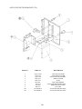
8 . CONTROL PANEL
In order to prevent an electric shock and short circuit, be sure to turn power off
before performing work by touching the interior parts of the product.
Be careful so as not to damage wirings. Damaged wiring can cause an electric shock
or short circuit accident. Work should be performed by Location’s Maintenance Man
or the Serviceman. Performing work by non-technical personnel can cause electric
shock or short circuit accident.
When performing work, use extreme care so as not to exert excessive load or
impact to the parts and Control Panel. Careless working can cause injury and or
deformation, damage and loss of parts.
The Control Panel of this product has the mechanism in which the motor, clutch, volume, etc.
are used. Periodically check the Control Panel in the Test Mode to see if there is any fault,
and cope with the problem if any at an early stage. Also, once a month, apply greasing to the
mechanism part.
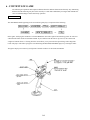
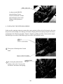
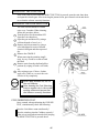
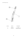
8 - 1 GREASING
Once a month, open the Control Panel and apply greasing to the mechanism part. For Spray Grease,
Use Grease Mate (Part No. 090-0066).
37
As shown in the PHOTO,
insert the Spray Grease
Nozzle to the inside of Guide
plate and apply grease to the
sliding friction portions of
the part.
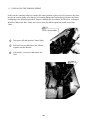
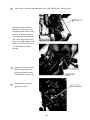
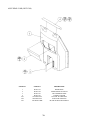
8 - 2 REPLACING THE EXTENSION SPRING
In the case the centering action (to return to the center position) of the reel (rod) is inactive, the cause
may be the secular change of or damage to Extension Spring and Torsion Spring. Replace the Extension Spring in the following procedure. Prepare a Spanner (width across flats: 5mm), narrow-edged
flat blade type screwdriver, and Philips type screwdriver (M3 and M4 screws).
1 Turn power off and open the Control
Panel.
2 By securing the pin head with
spanner, remove the 2 screws with
screwdriver and remove the Spring.
38
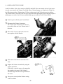
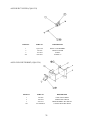
3 By using the narrow-edged flat
blade type screwdriverr remove
the E rings.
5
Remove the 2 pins. Use care so as not to
lose the Collar.
4
Take out the 34 screws and remove
the Guide Plate.
6
Remove the two E-Rings and the Spring.
7 Replace the Spring.
By refering to the ASSY DRAWING HOT-3100, install the Spring, E-Ring, Washer, etc. in the
correct sequential order.
39
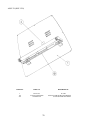
8 - 3 REPLACING THE TORSION SPRING
In the case the centering action (to return to the center position) of the reel (rod) is inactive, the cause
may be the secular change of or damage to Extension Spring and Torsion Spring. Replace the Extension Spring in the following procedure. Prepare a Philips type screwdriver for M4 screw, a Hexagon
Wrench (width across flats: 2mm), and a screw driver for M4 Hexagon Nut (width across flats:
7mm).
1
Turn power off and open the Control Panel.
2
Take out 2 screws and remove the Volume
together with the Bracket.
3
Take out the 2 set screws and remove the
Gear.
40
4
Take out the 2 Hexagon Nuts and remove the Pillow Block and Torision Spring.
When removing the Pillow
Block, be sure to remove the
straight from the Shaft. Removing it in an inclined direction
can make work more difficult
and cause injury hazard. Also,
this can cause the oppisite side
Shaft to be subject to an excessive load and cause Shaft
damage.
5
Replace the Spring. Ensure
that the longer part of the
Spring is positioned to the
Control Panel’s center side.
6
Reassemble by using the
oppisite procedure.
41
8 - 4 REPLACING THE VOLUME
In the Test Mode, if the value variation of ROD X and ROD Y does not match with reel (rod) operation, the cause may be the Volume Gear Mesh failure, Volume damage, etc. Replace the Volume in
the following procedure. Explanations of Volume replacement in the X direction are given below.
The Volume in the Y direction is the one to be removed when replacing the Torsion Spring. Prepare a
philips type screwdriver for M4 screw and flat-blade type screwdriver for M3 Cheese Head.
1 Turn the power off and open Control Panel.
2 Disconnect the Volume Connectors.
The red one is the connector in the X direction, and the blue one is the Volume in the Y
direction.
3 Take out the 2 screws and remove the Volume together with the Bracket.
4
Take out the 2 Set Screws and remove the
Gear.
5
Replace the Volume. Assemble by using the
oppisite procedure.
At this time, cause the gears to be engaged in
the periphery the center of the Volume’s
movable range when the reel is positioned at
the center.
6
Turn power on and perform Volume setting
in the Test Mode.
42
8 - 5 REPLACING THE INTERNAL PARTS OF REEL
Replace the internal parts of reel by using the following procedure.
prepare a Philips screwdriver for M3 screw.
1
Turn the power off.
2
Take out 2 screws and remove Cover U.
3
4 Remove the Connector and replace the
Board.
5 Assemble by using the oppisite procedure.
6 Turn the power on and perform Volume
setting in the Test Mode.
43
Internal SW, etc. can be removed.
9 . COIN SELECTOR
In order to prevent an electric shock and short circuit, be sure to turn
power off before performing work by touching the interior parts of the
product.
Be careful so as not to damage wirings. Damaged wiring can cause an
electric shock or short circuit accident.
When cleaning the Coin Selector, be sure to use a soft cloth. If the
Coin Selector is badly soiled, remove the stains by using a soft cloth
dipped in water or warm water and then squezzed dry. Never use
chemical detergents or chemicals.
If the Coin Selector is taken out for cleaning or checking, ensure that
Coin Slector is accuratley functioning after it is returned in place.
The Coin Selector is employed for this product. If the Coin Selector’s coin passage is soiled, the coin
selection accuracy is deteriorated. Be sure to perform cleaning once every 3 months. Although
rarely, coin jam occurs in the periphery of the Coin Selector. Should coin jam occur, or for cleaning,
take out the Coin Selector from the machine.
9 - 1 TAKING OUT THE COIN SELECTOR
1
Turn Power off.
2
Open the Coin Chute Door.
3
While pulling the Coin Chute Bracket’s white
stopper, bend it towards the arrow direction
shown.
4
First lift the Coin Selector up and then take it
out from the Bracket in the manner of pulling
it diagonally upward.
44
HANDLING THE COIN JAM
If the coin is not rejected when the REJECT BUTTON is pressed, open the coin chute door
and open the selector gate. After removing the jammed coin, put a normal coin in and check
to see that the selector correctly functions.
CLEANING THE COIN SELECTOR
1
2
3
4
5
6
The coin selector should be cleaned
once every 3 months. When cleaning,
follow the procedure below:
Turn the power for the machine OFF.
Open the coin chute door.
Open the gate and dust off by using a
soft brush (made of wool, etc.).
Remove and cleen smears by using a
soft cloth dipped in water or diluted
chemical detergent and then squeezed
dry.
Remove the CRADLE.
When removing the retaining ring(Ering), be very careful so as not to bend
the shaft.
Remove stain from the shaft and pillow
portions by wiping off with a soft cloth,
etc.
After wiping as per #5 above, further
apply a dry cloth, etc. to cause the coin
selector to dry completely.
Never apply machine oil, etc. to
the coin selector
After cleaning the Coin Selecting,
Insert a regular coin in the normal
working status and ensure that
the Selector correctly functions.
COIN INSERTION TEST
Once a month, when performing the COIN SW
TEST, simultaneously check the following:
Does the Coin Meter count satisfactorily?
Does the coin drop into the Cashbox correctly?
Is the coin rejected when inserted while keeping
the REJECT BUTTON is pressed down?
45
OPTIONAL DOLLAR BILL ACCEPTOR
THE COIN DOOR ASSEMBLY USED ON SEGA BASS FISHING COMES
EQUIPPED TO ACCEPT A DOLLAR BILL ACCEPTOR. ALL NEEDED
WIRING CONNECTIONS ARE CONVIENENTLY LOCATED INSIDE THE
GAME FOR THIS APPLICATION.
THE COIN DOOR CAN ACCCOMMODATE THE FOLLOWING
VALIDATORS:
HOLE POSITION#1
(FORWARD-MOST POSITION)
VFM5 (MARS)
HOLE POSITION#2
VFM2 (MARS)
VFM4 (MARS)
DBV45 (JCM)
HOLE POSITION #3
CURRENTLY NOT USED
HOLE POSITION #4
DSI01*
*The back flange on the chute can be removed for hold position #4.
If the flange is not removed, it may interfere with the back of the
cabinent.
46
10. MONITOR
10 - 1 CAUTIONS AND WARNINGS CONCERNING SAFE HANDLING OF MONITOR
When performing such work as installing and removing the monitor, inserting and disconnecting the external connectors to and from monitor, be sure to disconnect the power connector
(plug) before starting work. Proceeding the work without following this instruction can cause
electric shock of malfunctioning.
Using the monitor by converting it without obtaining a prior permission is not allowed. SEGA
shall not be liable for any malfunctioning and accident caused by said conversion.
Primary side and secondary side
The monitor’s circuit which is divided into the Primary
side and secondary side, is electrically isolated. Do
not touch the primary side and the secondary side
simultaneously. Failing to observe the instruction can
cause electric shock, and this is very dangerous.
When making monitor adjustments, use a nonconductive driver and make adjustment without
touching any other part other than the Adjustment
V.R. and Knob. Also, be sure not to cause a shortcircuit to the Primary side and the Secondary side. If
short-circuited, it can cause electric shock or malfunctioning, which is very dangerous.
High tension Voltage
Some of the parts inside the monitor are subject to high-tension voltage in excess of 20,000
volts and very dangerous. Therefore, do not touch the monitor interior. Should soldering &
paper wastes, etc. be mixed in the monitor, turn the power off so as not to cause malfunctioning or fire hazard.
Connecting the CRT and PCB
For combining the CRT and PCB, use the specified part No. to maintain the status of adjustments made at the factory. The anode of the CRT itself will be accumulitavely charged as time
elapses, generating high tension voltage which is very dangerous. The monitor should be used
with the Chassis, CRT and PCB assembled. When repair, etc. is required at the time of malfunctioning, be sure to send it in an “as assembled” condition. If these are disassembled, what’s
charged to said high tension voltage can be discharged, causing a very hazardous situation.
Therefore, under no circumstances should it be disassembled.
Static Electricity
Touching the CRT surface sometimes causes you to slightly feel electricity. This is because the
CRT surfaces are subject to static and will not adversly affect the human body.
Installation and removal
Ensure that the Magnetizer Coil, FBT (Fly-Back Transformer), Anode Lead and Focus Lead are
not positioned close to the sheet metal work’s sharp edges, etc. and avoid damaging the
insulated portions so as not to cause an electric shock and malfunctioning. (For the name of
parts, refer to the above figures.)
47
For the purpose of static prevention,
special coating is applied to the CRT
face of this product. To protect the
coating, pay attention to the following
points. Damaging the coating film can
cause electric shock to the customers.
For the caution to be heeded when
clearing, refer to the Section of Periodic
inspection Table.
Do not apply or rub with a hard item (a
rod with pointed edge, pen, etc.) to or
on C.R.T. surfaces.
Avoid applying stickers, seals, etc. on
the C.R.T. face.
Do not remove aluminum foils from the
C.R.T. corners. Removing the aluminum
foils can cause static prevention effects
to be lowered.
10 - 2 CAUTIONS TO BE HEEDED WHEN CLEANING THE CRT SURFACES
Static preventive coating is applied to the CRT surfaces. When cleaning, pay attention to the following points. Peeling off static prevnetive
coat can cause electric shock.
Remove smears by using a dry, soft cloth (flannels, etc.). Do not
use a coarse gauze, etc.
For smear removing solvent, alcohol (ethanol) is recommended.
When using chemical detergent, be sure to follow instructions
below:
*Dilute chemical detergent with water and dip soft cloth in and then
thoroughly wring it to wipe smears off.
*Do not use a chemical detergent containing an abradant, powder or
bleaching agent.
*Do not use alkaline chemical detergents such as “glass cleaner” available on the market or solvents such as thinner, etc.
Do not rub or scratch the CRT face with hard items such as
brushes, scrub brush, etc.
48
10 - 3 ADJUSTMENT METHOD
Monitor adjustments have been made at the time of shipment. Therefore do not
make further adjustment without a justifiable reason. Adjusting the monitor which
contains high tension parts is dangerous work. Also, an erroneous adjustment can
cause deviated synchronization and image fault, resulting in malfunctioning.
To determine whether or not the adjustment is needed, make judgment by watching
the monitor’s adjustment screen of the replaced Game Board. Normally, monitor
adjustment is made with knobs and switches on the Adjustment Board that can be
seen by opening the Control Panel Base. Note that in the monitor of this product,
correct images can not be obtained unless the settings of the horizontal frequency
or video input connector (input impedance/input level) are compatible with the
board. When the Game Board is replaced, check the settings.
First unplug the plug and then operate the switch. Operating the switch as is energized can
cause damage and malfunctioning. Connect only the video input connector which is set in the
maner consistent with the Game Board, Connecting any one other than the set connector or
setting from the predetermined setting can cause malfunctioning.
49
Use the knobs and connectors that can be seen by
removing the Maintenance Hatch on the backside of
the cabinet, normally as is at the time of shipment. In
particular, do not touch the knobs not explained herein.
When replacing the Game Board or the Monitor,
ensure that the direction of the connector’s connection
is correct as per the Game Board manual. If the
connecting direction is wrong, the image is inverted or
turned as shown below.
50
10 - 4 REMOVAL/REPLACEMENT OF MONITOR
When performing such work as monitor installation/removal, or inserting/disconnecting the external Connector connected to the monitor and its interior, first be
sure to disconnect the power connector (plug). Working with the power plug as is
connected can cause electric shock or malfunctioning.
When replacing the monitor, be very careful. To avoid electric shock, etc., personnel other than those who have technical expertise are not allowed to replace the
monitor.
Perform the assembly work by following the procedure herein stated. Failing to
comply with the instructions can cause an electric shock.
Be sure to use 2 or more persons for replacing the monitor. performing the replacement work by only one person can cause injury or parts damage.
To ensure performing the work safely, provide sufficient space. Working in places
with narrow space can cause injury or working errors.
Be careful so as not to damage wirings. Damaged wiring can cause an electric shock
or short circuit accident.
Do not touch places other than those specified. touching places not specified can
cause an electric shock or short cicuit accident.
After the vertical/horizontal transposition of the MONITOR, monitor adjustments may
be required.
For performing the monitor’s vertical/horizontal transposition in the manner consistent with the Game Board, follow
the procedure below:
1 After turning the AC Panel’s main SW off,
unplug from the Socket Outlet.
2 Open the Control Panel Base.
Pull the knob in the square hole inside the base
downward. The lock will be unlocked and the
Mask can be removed.
3 When the Mask is removed, the Connector Plate
appears. If the CRT is positioned horizontally, the
Connector Plate is underneath the CRT, and if the
CRT is positioned vertically, it is on the right
hand side. Disconnect all of the connectors
connected to the Connector Plate.
4 If the monitor’s video input connector is D-SUB
MINI connector, disconnect by removing the
Maintenance Hatch on the backside of the
cabinet.
5 Remove the nuts and spring washers which
secure the 4 corners of the monitor.
51
1
By holding the Monitor’s sheet metal
portion, pull out the monitor from the
cabinet. Since the Monitor is a heavy
item, be sure to use 2 workers to
perform this work.
2
When installing the monitor to the
cabinet, to position the CRT vertically,
ensure the Connector Plate is on the
right-hand side of the CRT and position
the CRT horizontally, ensure the
Connector Plate is underside the CRT.
3
Install the Spring and Nut for the
monitor’s four corners.
4
In the manner consistent with the
Game Board setting, connect the video
input connector, and make connector
connection with the other 2 connectors
of the Connector Plate.
5
Operate the mode change switch in the
manner consistent with the Game
Board setting.
6
Install the mask. Insert the 2 Mask
holders which are projecting from the
upper part of the Front Piece’s Mask
installation portion into the Mask’s 2
slits, and press the Mask’s underside in.
52
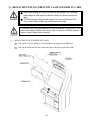
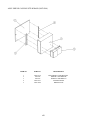
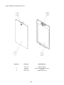
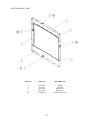
11. REPLACMENT OF FLUORESCENT LAMP AND DISPLAY CARD
When performing the work, be sure to turn power off. Working
with power on can cause an electric shock or short circuit accident.
The Flourescent Lamp, when it gets hot, can cause burns. Be
very careful when replacing the Fluorescent Lamp.
To perform work safely and securely, be sure to prepare a step which is in a
secure and stable condition. Not using a step or using an unstable step can
cause a violent falling down accidents.
11 -1 REPLACEMENT OF FLUORESCENT LAMP
1
Take off the 2 screws which secure the Holder on the upper part of Billboard.
2
Take out the billboard from the cabinet and replace the fluorescent lamp (20W)
53
11 - 2 REPLACMENT OF DISPLAY CARD
To be performed if Display Card is damaged or if Game Board is replaced.
1 Turn Power off.
2 Remove the 2 truss screws which secure the
Billboard Cover.
3 Remove the Billboard Cover diagonally upward.
4 The Display Card is adhered to the backside of the
Billboard Panel inside the Billboard cover.
5 Peel off the Display Card and adhere the replacement Display Card. The adhesive tape is on the
Display Card surface.
54
12 . PERIODIC INSPECTION TABLE
The items listed below require periodic check and maintenance to retain the performance of
this machine and ensure safe operation.
Be sure to check once a year to see if Power Cords are damaged,
the plug is securley inserted, dust is accumulated between the
Socket Outlet and the Power Plug, etc. Using the product with
dust as is accumulated can cause a fire or electrical shock.
Periodically once a year, request the place of contact herin stated
or the Distributer, etc. where the product was purchased from, as
regards the interior cleaning. Using the product with dust as is
accumulated in the interior without cleaning can cause a fire or
accident. Note that cleaning the interior parts can be performed
on a pay-basis.
ITEMS
DESCRIPTION
PERIOD
CHASSIS
Volume V.R. inspection
Greasing to gears and pillows
Memory Test
Setting Check
SW Volume inspection
Line Inspection
Line Replacement
Check COIN SW
COIN SELECTOR cleaning
Screen cleaning
Check adjustments
Setting check
Cleaning
Inspection and cleaning
Cleaning
Monthly
Semi-annually
Monthly
Monthly
Monthly
Monthly
Semi-annually
Monthly
Trimonthly
Weekly
Monthly
Monthly
Annually
7
8
8
7
9
10
4, 7, 10
7
see above.
As necessary
see below
CONTROL MECHA
(pole)
COIN SELECTOR
MONITOR
GAME BD
INTERIOR
POWER PLUG
CABINET SURFACES
55
REERENCE
1
1
13 . TROUBLESHOOTING
Should trouble occur, first check connector connections.
PROBLEMS
CAUSE
With Main SW
ON, no activation
Power is not supplied.
Plug in correctly
Power supply/voltage is not correct.
Make sure that power supply/voltage is
AC main fuse causes the
power to be cut off due to momentary
overload.
Check fuse. Remove the cause of
overload and replace fuse
Volume Setting Failure
Perform Volume setting
Encoder malfunctioning
The fuse is blown due to an overload.
Brake malufunctioning
Thermal element functioned
Replace Encoder.
Replace Fuse.
Replace Brakes
Activates @70°C, recovers after cool-off.
Irregular sound
emitted from
inside Rear Cabinet
Greasing to gear mesh portion is not
satisfactory, or extraneous matter
mixed in.
Apply greasing or eliminate extraneous
matter.
The color of the
image on PROJ.
screen is incorrect.
Connector connections are defective.
Check the connection for the RGB and
SYNC connectors of the PROJ. TERM.
BD and VPM BUFFER BD.
The image on PROJ.
screen has color
deviation.
Affected by the magnetic field of
installation location.
Make CONVERGENCE adjustment.
(Refer to Section 9.)
No sound is emitted.
Sound Volume adjustment is not
appropriate.
Adjust sound volume. (see Section 6).
Sound BD and speaker are
malfunctioning.
Perform sound test to find and replace
defective parts.(Refer to Section 6).
Lateral mecha does
not function.
Motor’s Overheat.
Motor replacement is needed. (Check Motor
Driver as this may be malfunctioning.)
The Fluorescent
lamp does not
light up.
The Fluorescent tube is burnt out.
Replace the Fluorescent tube
(Refer to Section 10).
Switches of
Control Panel
do not function
correctly
Connection fault of connector
between Front and Rear Cabi.
Accurately connect the connector.
Rod Controller’s
Movements are
unsatisfactory
COUNTERMEASURES
56
14 . GAME BOARD
In order to prevent an electrical shock, be sure to turn power off before
performing work by touching the interior parts of the product.
Be careful so as not to damage wirings. Damaged wiring can cause an
electric shock or short circuit accident.
Do not expose the Game BD, etc. without a good reason. In this product,
setting changes are made during the test mode. The Game BD need not be
operated. Use the Game BD, etc. as is with the same setting made at the
time of shipment.
The Game Board replacement method depends on the type of the present Game Board and that of
the Game Board to replace with. Herein, how-to-remove the previously installed Game Board is
explained. Regarding the method of connecting the Game Board for replacement, refer to the instructions of that particular Game Board. When replacing the ST-V cartridge, first take out the Game
Board from the cabinet as per the following procedure. Changing the cartridge within the cabinet can
damage parts and wirings.
Note that when the Game Board is replaced, the monitor’s frequency change, video input
connector’s reinsertion, and screen adjustment may be needed.
14 -1 TAKING OUT THE GAME BOARD
1
Turn Power off.
2
Remove the Service Door.
3
Disconnect all the connectors connected
to the Shield Case. In the case of the
Game Board for which the Shield Case is
not used, disconnect all of the connectors
connected to the Game Board.
4
Remove the Wing Bolt which secures the
Base Board mounting the Shield Case
(Game Board)
5
Pull out the Base Board with the Shield
Case (Game Board) as is mounted, from
the cabinet. At this time, to avoid wiring
damage, use care so that wires are not
caught.
57
6
Take Out the 3 screws and the Shield Case
Lid to remove the Game Board.
14 - 2 COMPOSITION OF GAME BOARD
GAME BD BSS
(833-13317)
NOTE: THIS PICTURE IS FOR REFERENCE ONLY!! UNIT IS NOT TO BE OPENED. EXPOSING THE GAME
BD FOR ANY REASON MAY VOID WARRANTY.
58
15 . DESIGN RELATED PARTS
59
16 . PARTS LIST
TOP ASSY GET BASS STD
60
TOP ASSY GET BASS STD
ITEM NO.
PART NO.
1
2
3
4
5
6
9
10
11
12
101
HOT-10002
HOT-3000-01
HOT-3080
HOT-0001
HOT-0002
HOT-0003
HOT-0300
422-0684-01
422-0685-01
429-0619-01
260-0074
260-0075
032-000420
031-000416-0C
050-F00400
000-P00408-W
000-P00330
201
202
203
204
205
DESCRIPTION
ASSY CABINET 24K 750 OHM HC
ASSY FISHING CTRL PNL HOT EXP
ASSY VOLUME X
REINFORCE BRKT L
REINFORCE BRKT R
FAN BRKT
ASSY SHIELD CASE BSS STD W/BASE
PLAY INSTR SH BSS STD EXP
SUB INSTR SH BSS STD EXP
DISPLAY CARD BSS STD EXP
FAN MOTOR DC24V 2410NL-05W-B50
FAN MOTOR DC24V 2410ML-05W-B50
WING BOLT M4X20
CRG BLT CRM M4X16
FLG NUT M4
M SCR PH W/FS M4X8
M SCR PH M3X30
61
ASSY SHIELD CASE BSS STD W/BASE (HOT-0300)
ITEM NO.
PART NO.
1
2
3
4
5
HOT-0310
105-5246
105-5247
HOT-0101
HOT-4500
DESCRIPTION
ASSY SHIELD CASE BSS STD
SHIELD CASE BRKT W
SHIELD CASE BRKT N
WOODEN BASE
DRIVER UNIT
62
ASSY SHIELD CASE BSS STD (HOT-0310)
ITEM NO.
PART NO.
DESCRIPTION
1
2
3
4
101
105-5240Y
105-5242X-01
839-0951
833-13416
260-0064
SHIELD CASE MODEL 3
SHIELD CASE LID MODEL 3
FILTER BD MODEL 3 JPT
GAME BD BSS STD
FAN MOTOR DC12V
63
ASSY SHIELD COVER (HOT-1004)
ITEM NO.
PART NO.
DESCRIPTION
1
2
201
200-5258
200-5506
000-P00408-W
MONITOR SHIELD
SHIELD STAY LONG
M SCR PH W/FS M4X8
64
ASSY FRONT CABI (HOT-1100)
65
ASSY FRONT CABI (HOT-1100)
ITEM NO.
PART NO.
1
2
3
4
5
8
9
10
12
13
14
15
16
17
18
19
20
24
25
26
28
29
101
102
HOT-1101X
HOT-1102
HOT-1103X
HOT-1104
HOT-1105
HOT-1108
HOT-1109
HOT-1110
HOT-1112
HOT-1113
CQN-1313
HOT-1200
BOX-CASH
HOT-1116
HOT-1270
HOT-1250
HOT-1119
HOT-1120
HOT-1121
HOT-1202
839-0894
HOT-1125
220-5420
601-6999
601-8810
509-5028
509-5453-V-B
601-8726
130-5156
509-5762
509-5763
000-T00512-C
012-T00410-0C
012-P00312
010-P00406-F
012-F00310
047-PA3207-6
000-P00512-W
000-F00410
000-F00308
012-P00316
012-P00412
012-P00410
012-P00306
103
104
107
108
110
201
202
204
205
206
207
208
209
210
211
212
213
214
DESCRIPTION
66
FRONT PIECE
BILLBOARD COVER
BILLBOARD PNL
MASK HOLDER UPPER
REINFORCE
SPEAKER BRKT
MIDDLE FRAME
LOCK UNIT
COIN CHUTE
BD HOLDER UPPER
LOCK BRKT
ASSY CASH BOX DOOR
CASHBOX
COIN CEILING
ASSY COIN CHUTE DOOR
ASSY SERVICE DOOR
DOOR SW BRKT
REINFORCE PLATE R
REINFORCE PLATE L
FRAME CASH BOX DOOR
TERMINAL BD
SPACER
RHEO STAT 100 OHM 10W
KNOB 18 SERRATION
KNOB MR-1512-1T
SW PB 1M
SW ROCKER J8 V-B
CATCH F
SPEAKER BOX 8 OHM
LINE INTERRUPT SWITCH
LINE INTERRUPT SWITCH
M SCR TH CRM M5X12
TAP SCR TH CRM 4X10
TAP SCR PH 3X12
S-TITE SCR PH W/F M4X6
TAP SCR FH 3X10
RVT OPEN TYPE AL 3.2X7.6
M SCR PH W/FS M5X12
M SCR FH M4X10
M SCR FH M3X8
TAP SCR PH 3X16
TAP SCR PH 4X12
TAP SCR PH 4X10
TAP SCR PH 3X6
ASSY CASH BOX DOOR (HOT-1200)
ITEM NO.
PART NO.
DESCRIPTION
1
3
4
5
202
HOT-1201
220-5574
HOT-1203
HOT-1204
065-E00300
CASH BOX DOOR
CAM LOCK W/KEYS
CENTER TNG
SIDE TNG
E RING 3MM
67
ASSY SERVICE DOOR (HOT-1250)
ITEM NO.
PART NO.
DESCRIPTION
1
2
3
4
HOT-1251
220-5575
DP-1167
HOT-1252X
SERVICE DOOR
CAM LOCK MASTER W/O KEY
TNG LKG
PAPER INSULATOR
68
ASSY COIN CHUTE DOOR (HOT-1270)
ITEM NO.
PART NO.
DESCRIPTION
1
2
3
4
5
6
7
8
9
201
202
CQN-1320X
CQN-1321
CQN-1324
HOT-1271
HOT-1272
220-5208~
220-5575
250-5043
DP-1167
010-P00306-F
010-P00408-F
69
COIN CHUTE DOOR
ASSY REJECT LEVER
ASSY COIN CHUTE BRKT
REJECT LEVER
FLAP
COIN CHUTE REJR~
CAM LOCK MASTER W/O KEY
REJECT BUTTON ASSY
TNG LKG
S-TITE SCR PH W/F M3X6
S-TITE SCR PH W/F M4X8
ASSY REAR CABI (HOT-1300)
ITEM NO.
PART NO.
DESCRIPTION
1
2
3
4
203
204
205
HOT-1301
HOT-1304
HOT-1303
HOT-1305
012-T00410-0C
000-T00410-0C
000-P00412-WB
REAR PIECE
MAINTENANCE HATCH
LID COMMUNI PORT
HANDLE COVER
TAP SCR TH CRM 4X10
M SCR TH CRM 4X10
M SCR PH W/FS BLK M4X12
70
ASSY REJECT LEVER (CQN-1321)
ITEM NO.
PART NO.
DESCRIPTION
1
2
3
201
CQN-1322
CY-1032
123-0035
069-0039
REJECT LEVER BRKT
REJECT LEVER
SHAFT
E RING 3.2
ASSY COIN CHUTE BRKT (CQN-1324)
ITEM NO.
PART NO.
DESCRIPTION
1
2
3
201
CY-1009
105-5041
220-5272
010-P00408-F
COIN CHUTE BRKT
UPPER COIN CHUTE
CHANNEL BRKT W/O SHUTE
S-TITE SCR PH W/F M4X8
71
ASSY FL (HOT-1350)
ITEM NO.
PART NO.
DESCRIPTION
1
101
201
HOT-1351
LOCAL PURCHASE
010-P00416-F
72
FL LID
ASSY FL 20W SD W/CONN HIGH S
S-TITE SCR PH W/F M4X16
ASSY MASK (HOT-1400)
ITEM NO.
PART NO.
DESCRIPTION
1
2
3
4
201
HOT-1401
601-8725
HOT-1402
HOT-1403
012-P00310
MASK
CATCH M
PACKING L
PACKING S
TAP SCR PH 3X10
73
ASSY FISHING CNTRL PNL HOT EXP (HOT-3000-01)
74
ASSY FISHING CNTRL PNL HOT EXP (HOT-3000-01)
ITEM NO.
PART NO.
1
2
3
4
5
6
7
8
9
10
11
13
14
15
16
17
18
19
20
21
22
23
24
25
26
27
29
30
31
32
33
34
35
36
37
38
39
40
41
42
43
44
45
46
47
48
49
50
HOT-3001
HOT-3002-01
HOT-3003X
HOT-3004
HOT-3005
HOT-3006
HOT-3007
HOT-3050
HOT-3008
HOT-3009
HOT-3010
HOT-3012
HOT-3013
HOT-3014
HOT-3100
HOT-3015
HOT-3016
HOT-3017
HOT-3018
BSS-2907
HOT-3020
HOT-3021
HOT-3022
HOT-3023
HOT-3060
HOT-3070
HOT-3024
HOT-3090
HOT-3025
BSS-3001Z
BSS-3002Z
BSS-3003
BSS-3004
BSS-3005
BSS-3006
BSS-3007
BSS-3008
BSS-3009
BSS-3010
BSS-3011
BSS-3012
BSS-3013
BSS-3014
BSS-3015
BSS-3016Y
BSS-3017Y
BSS-3018
BSS-3040
DESCRIPTION
CNTRL PNL BASE BSS
CNTRL PNL PLATE BSS EXP
PROTECT RING
PILLOW BLOCK A
PILLOW BLOCK B
BEARING BRKT A
CENTER SHAFT
ASSY ROD
SPACER
PIN A
COLLAR A
DOME
SLIDE
DOME BRKT
ASSY GUIDE
TOR SPRING
SPRING HOOK PIN
SPRING HOOK ROLLER
GEAR LAST
KEY 3X3X8
SIDE SHAFT
GEAR M08Z20
GEAR M08Z60
BEARING BRKT B
ASSY CLUTCH
ASSY MOTOR
GEAR ENCODER
ASSY VOLUME
ROD TIP
COVER R
COVER L
COVER U
COVER S
BD HOLDER
CAST SW CAP
SELECT SW CAP
JOY STICK CAP
HANDLE BAR
HANDLE PIN
HANDLE GRIP
ORIGINAL NUT M8
SPACER A
SPACER B
SPACER C
HANDLE CAP
FRONT RING
FRONT RING SPRING
ASSY BRAKE W/PS
75
ASSY FISHING CNTRL PNL HOT EXP (HOT-3000-01)
ITEM NO.
PART NO.
DESCRIPTION
51
52
53
54
55
56
57
58
201
203
204
205
208
209
210
211
212
213
214
215
216
217
218
219
220
221
223
224
225
226
227
228
839-1003
839-1004
HOT-3026
HOT-3027
HOT-3028
HOT-3029
HOT-3030
HOT-3031
000-P00306-W
031-000416-0C
050-F00400
065-E00400
000-P00408-W
028-C00306-P
028-C00408-P
028-A00406-P
000-T00306-0U
000-T00308-0B
000-P00312-0B
FAS-000037
FAS-000038
FAS-500006
028-A00306-P
000-P00304-0B
050-C00400-3C
FAS-000045
060-F00500
060-F00400
060-S00400
050-H00400
050-F00500
028-C00410-P
STICK CONT BD.
REEL SW BD
PILLOW BLOCK C
GEAR ENCODER 2
COLLAR L
COLLAR S
INNER RING
CAUTION RING SHEET
M SCR PH W/FS M3X6
CRG BLT CRM M4X16
FLG NUT M4
E RING 4MM
M SCR PH W/FS M4X8
SET SCR CH CUP P M3X6
SET SCR CH CUP P M4X8
SET SCR HEX SKT CUP P M4X6
M SCR TH UCRM M3X6
M SCR TH BLK M3X8
M SCR PH BLK M3X12
M SCR BLK M3X35
M SCR PH BLK M3X45
CAP NUT TYPE 3 BLK M3
SET SCR HEX SKT CUP P M3X6
M SCR PH BLK M3X45
CAP NUT TYPE3 CRM M4
M SCR PH W/S BLK M3X6
FLT WSHR M5
FLT WSHR M4
SPR WSHR M4
HEX NUT M4
FLG NUT M5
SET SCR CH CUP P M4X10
76
ASSY BRAKE W/PS (BSS-3040)
ITEM NO.
PART NO.
DESCRIPTION
101
103
104
105
201
601-9942
512-5052-017
310-5376
370-5165-01-91
000-P00304-0B
POWDER BRAKE 0.1MM MITSUBISHI
POLYSWITCH RXE017
SILICONE SHEET
ENCODER 100PULSE W/O CONN
M SCR PH BLK M3X4
77
ASSY ROD (HOT-3050)
ITEM NO.
PART NO.
DESCRIPTION
1
201
301
HOT-3051
000-P00406-W
600-7016-014
ROD
M SCR PH W/FS M4X6
WIRE HARN ROD FLEX
78
ASSY CLUTCH (HOT-3060)
ITEM NO.
PART NO.
DESCRIPTION
1
2
3
4
101
201
202
203
204
HOT-3061
HOT-3062
HOT-3063
HOT-3064
601-10057
000-P00412-W
000-P00408-W
028-C00306-P
000-P00306-S
CLUTCH BRKT
GEAR CLUTCH IN
GEAR M08Z28
SHAFT HOLDER
PARTICLE CLUTCH
M SCR PH W/FS M4X12
M SCR PH W/FS M4X8
SET SCR CH CUP P M3X6
M SCR PH W/FS M3X6
79
ASSY MOTOR (HOT-3070)
ITEM NO.
PART NO.
DESCRIPTION
1
2
101
201
202
HOT-3071
HOT-3072
350-5535
028-C00408-P
000-P00412-W
MOTOR BRKT
GEAR M1Z22
MOTOR AC100V 8W
SET SCR CH CUP P M4X8
M SCR PH W/FS M4X12
80
ASSY VOLUME X (HOT-3080)
ITEM NO.
PART NO.
DESCRIPTION
1
2
101
201
HOT-3081
601-5410
220-5484
028-C00306-P
VOL BRKT
GEAR 15 FAI 6
VOL CONT B-5K OHM
SET SCR CH CUP M3X6
81
ASSY VOLUME Y (HOT-3090)
ITEM NO.
PART NO.
DESCRIPTION
1
2
101
201
HOT-3081
601-5410
220-5484
028-C00306-P
VOL BRKT
GEAR 15 FAI 6
VOL CONT B-5K OHM
SET SCR CH CUP P M3X6
82
ASSY GUIDE (HOT-3100)
ITEM NO.
PART NO.
DESCRIPTION
1
2
3
4
5
6
7
8
9
10
11
12
201
202
203
204
HOT-3101
HOT-3102
HOT-3103
HOT-3104
HOT-3105
HOT-3106
HOT-3107
HOT-3108
HOT-3109
HOT-3110
HOT-3016
HOT-3017
000-P00408-W
060-F00500
065-E00400
000-P00306-W
GUIDE PLATE
GUIDE HOLDER R
GUIDE HOLDER L
CUSHION
PIN B
COLLAR B
EXT SPRING
ROLLER HOLDER
STOP ROLLER
PIN C
SPRING HOOK PIN
SPRING HOOK ROLLER
M SCR PH W/FS M4X8
FLT WSHR M5
E RING 4MM
M SCR PH W/FS M3X6
83
DRIVER UNIT (HOT-4500)
84
DRIVER UNIT (HOT-4500)
ITEM NO.
PART NO.
DESCRIPTION
1
2
3
4
101
102
103
201
202
203
204
205
HOT-4501
HOT-4502
HOT-4503
839-1031
838-9507
400-5368-03024
601-7467
000-P00312-W
000-P00408-W
010-P00312-F
010-P00320-F
000-P00320-W
DRIVER BASE
DRIVER LID
CONN BRKT
ENCODER D/A BD
CLUTCH & MOTOR CONTROL BD
SW REGU LCA30S-24
L-LOCK BK
M SCR PH W/FS M3X12
M SCR PH W/FS M4X8
S-TITE SCR PH W/F M3X12
S-TITE SCR PH W/F M3X20
M SCR PH W/FS M3X20
85
ASSY CABINET 24K 750 OHM HC (HOT-10002)
86
ASSY CABINET 24K 750 OHM HC (HOT-10002)
ITEM NO.
PART NO.
1
2
3
4
5
6
7
8
9
10
11
HOT-1001
HOT-1100
HOT-1004
HOT-1002
HOT-1300
HOT-1350
CQN-1003
HOT-1003X
HOT-1400
HOT-1005-01
400-5325-02-91
400-5325-03
HOT-1006X
HOT-1007
HOT-15001
HOT-1008
HOT-1009
SGM-4420
200-5710
200-5642-24
220-5569
220-5570
999-0169
999-0167
050-H01000
000-P00408-WB
012-P00520-0C
012-T00410-0C
000-P00420-W
000-P00308-W
030-000616-S
010-P00306-F
010-P00412-F
008-T00408-0C
060-S01000
000-P00412-WB
030-000625-SB
068-652016-0B
000-F00512
000-P00308-W
12
13
15
31
32
33
101
102
103
104
201
202
203
204
205
206
207
209
210
211
212
213
214
215
216
217
DESCRIPTION
STUD BOLT
ASSY FRONT CABI
ASSY SHIELD COVER
LOWER BASE
ASSY REAR CABI
ASSY FL
GUTTER
STEP
ASSY MASK
CONN PLATE CRT
POWER SUPPLY UNIT EXP
POWER SUPPLY UNIT EXP
CONN BRKT PWR SPLY
LID COIN CNTR
ASSY HARD CONTROL BOX
SHADE
SW BD BRKT
AIR CAP COVER 900X900X1800
ASSY CLR DSPL 29AUTO MS-2931-S
ASSY CLR DSPL 29TYPE 24K 100V
MAG CNTR W/CONN
MAG CNTR W/CONN
CASTER 2 1/2"
LEG ADJUSTER
HEX NUT M10
M SCR PH W/FS BLK M4X8
TAP SCR #2 PH CRM 5X20
TAP SCR TH CRM 4X10
M SCR PH W/FS M4X20
M SCR PH W/FS M3X8
HEX BLT W/S M6X16
S-TITE SCR PH W/F M3X6
S-TITE SCR PH W/F M4X12
TMP PRF SCR TH CRM M4X8
SPR WSHR M10
M SCR PH W/FS BLK M4X12
HEX BLT W/S BLK M6X25
FLT WSHR BLK 6.5-20X1.6
M SCR FH M5X12
M SCR PH W/FS M3X8
87
ASSY HARD CONTROL BOX (HOT-15001)
88
ASSY HARD CONTROL BOX (HOT-15001)
ITEM NO.
PART NO.
DESCRIPTION
1
2
3
4
5
6
7
8
9
10
11
12
13
14
15
16
17
18
20
21
HOT-1501
HOT-1520
HOT-1503
HOT-1504
220-5575
HOT-1505
HOT-1522
HOT-1506
HOT-1521
HOT-1508
HOT-1510
HOT-1511
HOT-1512X
HOT-1513X
220-5167~
HOT-1515
HOT-1516
HOT-1517
HOT-1519
421-9823
CONTL PNL LOWER
LATCH N
SHAFT
LATCH HOLDER
CAM LOCK MASTER W/O KEY
LKG TNG
HINGE BSS HOT
CONTRL PNL UPPER
LOCK BRKT LONG
INSTRUCTION COVER
SHEET INSTR SPACE
TORSION SPRING
LATCH INSTR COVER R
LATCH INSTR COVER L
COIN ENTRY~
SPONGE A
SPONGE B
SPONGE C
SPONGE D
SW INSTR HOT
89
Come see Sega GameWorks Service Department’s Homepage