1
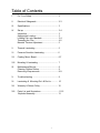
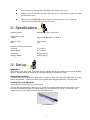
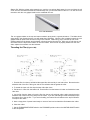
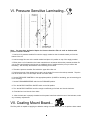
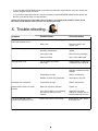
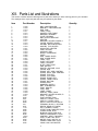
OPERATING
INSTRUCTIONS
ENTRY 4500
Model No. BA-EN45
Banner American Products, Inc.
Temecula, CA
CAUTION...
TO AVOID ANY DAMAGE,
PLEASE DO NOT USE
RAZORS OR SHARP
OBJECTS NEAR THE
ROLLERS.
Table of Contents
I.
For Your Safety ..................................................... 2
II.
Electrical Safeguards ........................................... 2-3
III.
Specifications ........................................................ 3
IV.
Set-up .....................................................................
Inspection ...............................................................
Appropriate Location ............................................
Loading Film onto Mandrels ................................
Threading the Film ................................................
Mandrel Tension Adjustment ..............................
V.
Thermal Laminating .............................................. 5
VI.
Pressure Sensitive Laminating ........................... 6
VII.
Coating Mount Board ........................................... 6-7
VIII.
Mounting & Laminating ........................................ 7
IX.
Maintenance/Service ............................................ 8
Cleaning Rubber Rollers ...................................... 8
Removing Wrap-arounds ..................................... 8-9
X.
Trouble-shooting ................................................... 9
XI.
Laminating & Mounting Do’s & Don’ts .............. 10
XII.
Warranty & Return Policy .................................... 10
XIII.
Parts List and Illustrations..................................11-12
Exploded Assembly .............................................. 13
1
3-4
3
3
3-4
4-5
5
Entry 4500 (BA-EN45)
Mandrel
I. For your safety...
u
Do not connect the laminator to electrical power or attempt to operate it until you have read
these instructions completely. Keep these instructions in a convenient location for future
reference.
u
Read all safety messages located in this instruction manual and on the laminator very carefully.
u
Always replace safety shield before operating your laminator. If you service this
machine yourself, ensure that the safety shield is returned to the operating position
when service is completed. Do this to protect all operators. Operators may be
harmed if you do not follow this instruction.
u
Removing feed table exposes hot and moving parts. This means that you can be harmed if you
remove the feed table. When the table is in the proper position the risk of injury to the operator
is reduced.
u
Do not operate this laminator without all detachable units installed correctly. This means that
there is risk of injury if this product is operated without all of its parts in their proper positions.
u
Keep hands and clothing away from rollers. The rollers are pinch points that can trap
body parts or clothing and cause serious injury.
u
Do not touch the front rollers while the laminator heater power is on. Turn rollers off and allow
to cool.
u
Do not use the laminator for other than its intended purpose.
u
Only operate this machine if you have been properly trained and authorized to do so. Contact
the manufacturer for training information at 909-296-9780.
II. Electrical Safeguards...
u
Never override or attempt to defeat electrical or mechanical safety interlock devices.
u
Disconnect power supply before servicing your laminator. This laminator uses double
pole/neutral fusing.
u
A readily accessible disconnect device should be incorporated in the fixed wiring.
u
The machine has been manufactured without a plug on the power cord. We recommend that
you connect this unit directly to a power main. Have a qualified electrician install your power
supply for you. Care must be exercised to properly identify the neutral wire in the power cord.
The neutral power cord wire is color coded white. The neutral of the power main should be
identified using a suitable voltmeter.
u
The laminator should only be operated from the type of power source indicated in these
OPERATING INSTRUCTIONS and on the serial label located on the rear panel of the unit.
u
Do not leave the laminator power on for extended periods while not in use. Open the panel
breaker at the end of the day as a precaution against a possible fire hazard.
2
u
Do not operate the laminator with a damaged power supply cord or plug.
u
Replace fuses only with same type rated 30A, 240V and 1A, 250V fuses. Contact your dealer
for replacement fuses.
u
There are two (2) EMERGENCY STOP buttons on your Entry 4500, one on each side.
Depressing one of these buttons will stop the rollers.
III. Specifications...
Operating Speed:
Adjustable to 5 fpm (2.54cm/sec.)
Power Requirements
Voltage:
Single Phase 208-240 VAC, 50/60 hz
Warm Up Time:
Fuse:
10-15 minutes
30 A
Maximum Laminating Dimensions
Thickness:
Width Capacity:
¼” (6.35mm)
45” (1143mm)
Net Weight:
Shipping Weight:
260 lbs (120 kg.)
360 lbs (165 kg.)
IV. Set-up...
Inspection:
Upon receipt of your Entry 4500, inspect the crate, the machine and all other contents of the crate for shipping
damage. Damage should be brought to the immediate attention of the delivering carrier.
Appropriate Location:
Your Entry 4500 must be placed on a sturdy table or stand in a clean, well lit area with ample space on all four
sides of the laminator. Contact your dealer for the optional stand designed especially for the Entry 4500.
Loading Film onto Mandrels
The following instructions apply to poly-in film rolls.
Top Roll: With the gripper spring away from you, pull the core gripper blade toward you and place the roll of
film onto the mandrel so that the film unwinds toward you from the bottom of the roll. Turn the roll on the
mandrel to lock the core gripper blade into the cardboard film core.
TOP MANDREL
3
Bottom Roll: With the gripper spring towards you, push the core gripper blade away from you and place the roll
of film onto the mandrel so that the film unwinds away from you from the bottom of the roll. Turn the roll on the
mandrel to lock the core gripper blade into the cardboard film core.
BOTTOM MANDREL
The core gripper blades on the top and bottom mandrels spring back in opposite directions. The blade should
spring back in the direction that the core will rotate when laminating. When the film is loaded properly the core
gripper blade will prevent the film from turning on the mandrel. When using poly-in rolls the top roll of film
should unwind from the bottom and the bottom roll should unwind from the top. With poly-out rolls the top roll
will unwind from the top and the bottom roll from the bottom. Once the film is properly loaded onto the mandrels, replace the mandrels onto the laminator.
Threading the Film (Figures 1&2)
1. Feed the film from the top roll behind the upper idler roller and lay it over both rollers. Be sure that the
adhesive side of the film is facing out and the non-adhesive side is against the roller.
2. To thread the lower roll, first drop the lower idler roller down.
3. Pull about 4’ of film from the bottom roll. Feed the film from the bottom roll under and behind the lower
idler roller.
4. Lay the film from the lower roll over the film from the top roll and both rollers, again ensuring that the
adhesive side of the film is facing away from the rollers. If you are cold loading it will be necessary to tape
the bottom film to the top film. If you are hot loading, the bottom film will adhere to the top film where it
overlaps at the rollers.
5. Have a large piece of poster board ready to use as a feed card to thread the film between the rollers.
6. Close the rollers.
7. Set the FORWARD/REVERSE switch to the FORWARD position and turn the MOTOR ON/OFF switch
to the ON position.
4
8. Turn the SPEED CONTROL knob far enough to allow the rollers to sufficiently pull the poster board into
the laminator. Keep in mind that varying films, media, and temperatures will require different speeds.
9. Feed the poster board between the rollers.
10. After the laminator is properly threaded and the poster board has exited the rear of the laminator,
make any necessary adjustments.
11. Attach film clip to exit of the rear of the lamination in center. This will help the film exit laminator
properly. Please see Figure 3 below.
Mandrel Tension Adjustment:
Mandrel tension must be set correctly to ensure good lamination quality. Adjust the tension by turning the
brake nut at the end of each mandrel.
To increase the tension, turn the brake nut clockwise. To decrease the tension, turn the brake nut counterclockwise. Adjust only 1/8 of a turn between tests. Use the minimum amount of tension necessary to achieve
good results. (See Section X Troubleshooting for possible tension adjustment problems).
V. Thermal Laminating...
1. Be sure all laminator parts (i.e. safety shield, feed table, etc.) are in their proper positions and the laminating film is loaded correctly (See page 3 for film loading instructions).
2. Set the temperatures according to the film manufacturer’s recommendations for the film you have chosen.
A low-melt film is recommended for inkjet prints. Keep in mind that the temperature at which you will laminate
will vary with different medias and laminating speeds. See the chart below for approximate temperature
ranges. The laminator will take approximately 10-15 minutes to reach operating temperature. The temperatures will be indicated on the LCD displays.
3 mil DIGIKote™
5 mil DIGIKote™
10 mil DIGIKote™
190°-210°F
220°-230°F
225°-235°F
3. Turn the MOTOR switch ON and perform a test lamination to ensure proper settings for successful lamination. Watch film as it exits the rollers so it doesn’t wrap around the rollers. It might be helpful to hold the film
at first when starting a lamination run. If any adjustments are necessary make them now and run another
test. Repeat this step until you obtain desired results.
4. Allow the Entry 4500 to run a small amount of film before feeding the print into the laminator to avoid a
dwell line across your print. Feed the print slowly and evenly, smoothing it as the rollers pull it through.
5. You may laminate subsequent prints now, leaving ample space between each print for trimming.
6. Once your last print has completely exited the laminator, turn the MOTOR switch OFF.
5
Rewind Option for Pressure
Sensitive Laminating...
VI. Pressure Sensitive Laminating...
Note: You must have the Rewind Option for Pressure Sensitive Films in order to laminate with
pressure sensitive material.
1. Load a roll of pressure sensitive film onto the supply mandrel so that it unwinds toward you from the
bottom of the roll.
2. Load an empty film core on the rewind mandrel and place it in position on top of the supply mandrel.
3. Either place a roll of material on the lower mandrel that is at least as wide as the pressure sensitive film
you are using and thread as usual or use an additional piece of media under the print you will be cold
laminating. This will keep the adhesive from transfering to the rollers.
4. Thread the pressure sensitive film behind the upper idler roller rod.
5. Peel back enough of the release liner to tape it to the empty film core on the take-up mandrel. Tape the
liner to the back of the core and drape the film over both rollers.
6. Set the PRESSURE CONTROL to the appropriate position (CLOSE for laminating; put red mounting pins
in for mounting).
7. Set the FORWARD/REVERSE switch to the FORWARD position.
8. Turn the MOTOR CONTROL ON/OFF switch to the ON position.
9. Turn the MOTOR CONTROL knob far enough to sufficiently pull a feed card into the laminator.
10. Feed the feed card into the front rollers.
11. After the laminator is properly threaded and the poster board has exited the rear of the laminator, make
any necessary adjustments.
VII. Coating Mount Board...
The Entry 4500 is capable of applying an adhesive coating to mount board that has not previous been coated.
1. Load a roll of adhesive, with the liner wound to the outside, onto the top mandrel in the same manner as
with laminating film.
2. Load a roll of paper on the bottom mandrel or use adhesive the same width as the mount board to keep the
adhesive from accumulating on the rollers.
3. Place mount pins in holes. (Please see picture below).
4. Set the temperature to approximately 125°F. The Entry 4500 will take approximately 10-15 minutes to
reach operating temperature. The roller temperatures are indicated on the LCD displays.
5. Feed the uncoated mount board into the laminator behind a small leader board. The leader board will
prevent the compression of the leading edge of your mount board.
6. You may coat subsequent boards now, one directly behind the other, so that the board in front becomes
the leader board. We recommend that you coat a sufficient supply of mount board in one session so you’ll
have it ready for future use.
VIII. Mounting & Laminating...
1. Be sure all laminator parts (i.e. safety shield, feed table, etc.) are in their proper positions and the laminating film is loaded correctly (See page 3 for film loading instructions).
2. Place mounting pins in proper holes.
3. Turn the TEMPERATURE CONTROL switch to the ON position.
4. Set the temperatures according to the film manufacturer’s recommendations for the film you have chosen.
The Entry 4500 will take approximately 10-15 minutes to reach operating temperature. The temperature of
the heated rollers are indicated on the LCD display.
5. Turn the MOTOR switch ON and perform a test mount to ensure proper settings for successful mounting.
If any adjustments are necessary make them now and run another test. Repeat this step until you obtain
desired results.
6. Position the print to be mounted on a section of mount board up to ¼” thick behind a leader board. The
leader board will prevent compression of the leading edge of your mount board.
8. Feed the print and mount board into the laminator behind the leader board slowly and evenly. Be sure to
pull back the release liner before it enters the rollers.
9. You may mount subsequent prints now, one directly behind the other so that the board in front becomes
the leader board.
10. Once your last print has completely exited the laminator, turn the MOTOR switch OFF and use a razor to
remove the mounted and laminated prints.
7
IX. Maintenance/Service...
Always use caution when servicing your laminator.
Precautions:
Disconnect the power supply and open the panel breaker
before attempting to service or repair the laminator.
Any maintenance or service should be preformed only by those
having appropriate technical training and experience. Contact
the manufacturer at 909-296-9780 for training information or
technical assistance.
Adjust only those controls that are specified in these operating
instructions.
Cleaning Rubber Rollers:
Excessive build-up of adhesive on the rollers may cause poor lamination quality and erratic film movement.
Use the following procedure to remove any adhesive from the laminating rollers.
1. Turn the HEATED ROLLERS off and allow the laminator to cool.
2. Cut the film where it comes off the top and bottom supply rolls. Pull any film out of the laminator and away
from the rollers.
3. Carefully remove the feed table to access the rollers. The feed table exposes hot and moving parts.
4. Disconnect the power supply.
5. Clean the exposed section of the rollers with a soft cloth dampened with an appropriate cleaning solution
such as isopropyl or denatured alcohol.
6. Reconnect the power supply and turn the FORWARD/REVERSE switch to the FORWARD position.
Turn the MOTOR switch to the ON position momentarily to expose a new section of the rollers.
7. Repeat steps 3-5 until the rollers are thoroughly clean.
8. Allow the rollers to dry completely before rethreading the laminating film.
Removing Wrap-Arounds:
Build-up on the rollers may cause a film wrap-around, especially when using thin film gauges. Follow the
procedure below to remove wrap-arounds.
1. Turn the HEATED ROLLERS OFF. Allow the laminator to cool.
2. Cut the film where it comes off the top and bottom supply rolls.
8
3. Open the ROLLER RELEASE handle on the side of the laminator and pull the film out of the unit that has
become wrapped around the rollers.
4. If you have a severe wrap-around, it may be necessary to use the REVERSE feature to back the film out.
Be sure to pull the film away from the laminator.
If there is a wrap-around on the lower roller, of if there is a run-away heat condition, please check
the sensor on the bottom roller to ensure it is touching the roller.
X. Trouble-shooting...
Symptom
Possible Cause
Corrective Action
LCD does not show display
when heat switches are on.
No power to laminator
Close panel breaker
Blown fuse
Disconnect power and
replace fuse
Laminator not set to optimal
laminating temperature
Adjust temperature slightly
upward.
Ink on print is wet
Allow ink to dry thoroughly
Paper is too slick
Use a more matte paper
Laminated item curls
Top or bottom film tension
is too high
Loosen tension on side (top
or bottom) that is curling up
Laminated item is wrinkled
Mandrel tension too loose
Increase mandrel tension on
side (top or bottom) that has
wrinkles
Temperature too high
Reduce temperature
Moisture in paper being laminated
Store paper in dry area
Laminated item is blistered
Temperature too high
Reduce temperature
Mandrel tension does not remain
constant
Brake nut improperly adjusted
Tighten nut
Core gripper blade is not preventing
the core from spinning on the
mandrel
Rotate film core while
holding the mandrel firm to
lock the blade into the core
Film is not bonding to the print
Too much heat with a lower
indicated heat readout on LCD
Bottom roller sensor not touching.
Ensure bottom roller sensor
is touching core
Do’s and Don’ts...
Read the instruction manual before operating your laminator.
Always run test samples before laminating valuable items.
Feed the print through slowly and evenly, smoothing it as it is pulled into the
laminator.
Operate the laminator with two rolls of the same width laminating film to avoid excessive
adhesive transfer to the rollers.
If laminator is not in current use, lower the heat setting or turn unit off.
Never feed abrasive materials or metal objects such as staples, paper clips, or glitter
through the laminator. Keep sharp objects like scissors and rulers away from the rollers
at all times.
Once an item has been fed between the rollers do not attempt to alter its position as this can damage the
print.
Do not stop the laminator before the item has completely exited from the rear to avoid a “dwell line” across
the print.
Do not clean or service the laminator before disconnecting the power supply.
XII. Warranty & Return Policy...
Warranty:
Your Entry 4500 is warranted to be free of defects in material and workmanship for a period of 1 year from the
date of original purchase. In the event of a defect in materials or workmanship, Banner American Products,
Inc. or its authorized dealer, will repair or replace (at their option) the laminator.
Banner American Products, Inc. makes no other warranty stated or implied except as stated above. This
warranty does not cover damage to the machine that occurs as a result of misuse or improper handling, or
damage to prints.
Return Policy:
If your laminator is not operating properly, first review the Operating Instructions and the troubleshooting guide.
If the malfunction cannot be corrected, contact your local dealer for instructions. Be sure to have your machine serial number and date of purchase handy.
If the laminator must be returned to the dealer, it is your responsibility to ensure that it is packaged properly.
Shipping damage as a result of improper packaging is not covered under the terms of this warranty.
10
XIII. Parts List and Illustrations
This section contains reference drawings and a parts list to assist you when ordering parts for your laminator.
The drawings show only those parts that may be replaced by the dealer.
Item
Part Number
Description
Quantity
1
2
3
4
5
6
7
8
9
10
11
12
13
14
15
16
17
18
19
20
21
22
23
24
25
26
27
28
29
30
31
32
33
34
35
36
37
38
39
40
41
42
43
44
45
46
47
48
50
51
52
53
54
55
56
57
58
59
60
11108
11109
11110
11111
11112
11113
11114
11115
11116
11117
11118
11119
11120
11121
11122
11123
11124
11125
11126
11127
11128
11129
11130
11131
11132
11133
11134
11135
11136
11137
11138
11139
11140
11141
11142
11143
11144
11145
11146
11148
11149
11150
7310
2434
2351
2775
8288
541
4031
1170
2386
2332
2369
6546
10124
2433
2324
2735
2325
BAR, CAM PRESSURE
BRACKET, CAM PRESSURE
ROD, CAM
TABLE, FEED
HOLDER, FEED TABLE
BRACKET, BEARING
PLATE, BEARING
BAR, ROLLER RELEASE
HEATER
BRACKET, HEATER GUARD, L
COVER, HEATER GUARD
HOLDER, BOTTOM HEATER
HOLDER, TOP HEATER
INSULATOR, HEATER
TUBE, HEATER
HOUSING, ROD
BLOCK, IDLER/DRIVE
IDLER
ROD, LOWER IDLER
ROD, UPPER IDLER
LABEL, LEFT
PLATE, LEFT SIDE
TABLE, RUN-OFF
PLATE, RIGHT SIDE
END, ROLLER
ROLLER, SILICONE, 35-40
COVER, SIDE
FRAME, LEFT SIDE CONTROL
FRAME, RIGHT SIDE CONTROL
FRAME, TOP LEFT
FRAME, TOP RIGHT
FRAME, FRONT LEFT
FRAME, FRONT RIGHT
FRAME, BOTTOM
FRAME, BACK
MANDREL, SUPPLY
BAR, THERMOSTAT
TUBE, ROLLER
TUBE, WIRE
LABEL, RIGHT
RUN-OFF TABLE, BACK
BRACKET, HEATER GUARD, R
FUSE, 1A, (MDL)
FUSE HOLDER, RL40
SWITCH, TOGGLE, RL40
SWITCH, TOGGLE, RL40
RELAY, SOLID STATE 25A DC
TERMINAL BLOCK, 6 STATION
DIGITAL READ OUT (NEW)
FEET, RUBBER, LARGE
OFFSET CAM COMPLETE RL43
CLAMP LEVER, RL40
BUSHING, IDLER FOR RL43
SWITCH, EMERGENCY STOP
CONTROL, HEAT, FINISHERS
FUSE, 30 AMP USA, RL40
MOTOR, RL40, 180V DC 42
POWER CORD WIRE, RL40
CHAIN, LINK, #35 MASTER
2
2
1
1
4
2
2
2
2
1
1
2
2
4
2
3
1
1
1
1
1
1
1
1
4
2
2
1
1
1
1
1
1
2
2
2
1
2
1
1
1
1
2
1
2
2
2
2
1
4
2
1
4
2
1
2
1
10
2
11
Item
Part Number
Description
Quantity
61
62
63
64
66
67
68
69
70
71
72
73
74
76
77
78
79
80
81
82
83
84
85
86
87
88
89
90
91
92
93
94
95
96
97
98
99
100
101
102
103
104
105
106
107
108
109
110
111
112
113
114
115
116
117
118
119
120
121
122
123
124
125
126
127
128
557
11045
4096
2379
2378
2777
11100
3032
3033
3034
8279
11167
11175
1172
11183
11184
11185
4268
11187
11188
11189
2740
2741
588
587
595
589
590
594
592
599
597
1326
598
10398
7251
1457
10878
2659
1087
2500
580
1450
1456
1458
2661
2828
349
2719
11190
1365
10837
11191
2322
4225
4227
4226
11192
11193
11194
11195
11213
11221
11222
11226
11333
KNOB, THERMOSTAT
VARIABLE SPEED CONTROL
CLAMP, POWER CORD
MAIN BODY BRAKE FOR RL43
BRAKE NUT FOR RL43
SWITCH, JOURNAL, EMERGENC
CAPACITOR, .01uF
HOLDER, SUPPLY MANDREL T
HOLDER, SUPPLY MANDREL B
MOUNT, CHASSIS
SENSOR, K TYPE
IDLER, UPPER, ENTRY 4500
BOX, 70 X 36 X 36, 600T
FUSE HOLDER, HTB-34I
LABEL, RIGHT
SPACER, ROLLER, ENTRY4500
SPROCKET, ROLLER
COLLAR, SET, 1.25 I.D.
COLLAR, SHAFT, 5/8"
SPROCKET, IDLER, 4500
SPROCKET, DRIVE, FRONT
WIRE, 10 AWG WHITE
WIRE, 10 AWG BLACK
WIRE, 14 GAUGE, WHITE
WIRE, 14 GAUGE, BLACK
WIRE, 18 GAUGE, WHITE
WIRE, 18 GAUGE, BLACK
WIRE, 18 GAUGE, BLUE
WIRE, 18 GAUGE, VIOLET
WIRE, 18 GAUGE, ORANGE
WIRE, 18 GAUGE, YELLOW
WIRE, 18 GAUGE, WHITE
WIRE, 18 AWG WHITE/BLACK
WIRE, 18 AWG, WHITE/RED
CHAIN, #35 BULK
CORE GRIPPER, MANDREL
SCREW, 10-24 X 1/2"
BOLT, HEX, 5/16-18 X 3/4
SCREW, 1/4-20 X 2" P.H.
SCREW, 6-32 X 3/8" PAN
SCREW, 1/4-20 X 3/4"
WASHER, 1/4 FLAT S A E
SCREW, 1/4-20 X 1/2" P.H.
SCREW, 10-24 X 1/2" FLAT
SCREW, 10-24 X 1/2"
SCREW, 1/4-20 X 3/4" P.H.
SCREW, 1/4-20 X 1", FLAT
SCREW, 8-32 X 3/8" P.H.
SCREW, 10-24 X 3/8" PAN
PALLET, ENTRY4500
NUT, 1/4 - 20
FHCS, 1/4-20 X 3/4
SHCS, 5/16-18 X 3
35BS17, 17T X STD. BORE
BRACKET, CORNER, 90 DEG
BRACKET, CORNER, 116.5 DG
BRACKET, CORNER, 153 DEG
SCREW, SET, 10-32 X 1/2
BOLT, SHOULDER,1/2 X 5/16
BHCS, 10-24 X 5/8
PHPS, 8-32 X 1/2 BLACK
SPROCKET, DRIVE, BACK
BUSHING, 1/2 X 5/8 X 1 LG
BUSHING, 1/2 X 5/8 X 1/2
MOUNT PIN, RED
BINDER CLIP
2
1
1
4
4
2
1
2
2
4
1
1
1
2
1
2
2
3
2
1
1
7’
7’
3’
2’
1’
1’
3’
1’
12’
1’
1’
6”
6”
5’
2
12
6
4
2
12
4
12
2
6
4
2
2
4
1
4
12
4
1
6
2
2
40
2
8
16
1
1
1
2
1
12
Exploded Assembly
13