1
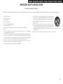
Professional DIGITAL DJ Mixier
DN-X600
Owner’s Manual
ENGLISH
DEUTSCH FRANÇAIS ITALIANO ESPAÑOL NEDERLANDS SVENSKA
IMPORTANT TO SAFETY
WARNING:
To reduce the risk of fire and electric shock, this apparatus should not be
exposed to rain or moisture and objects filled with liquids, such as vases,
should not be placed on this apparatus
CAUTION:
USE OF CONTROLS OR ADJUSTMENTS OR REFOR-MANCE OF PROCEDURES
OTHER THAN THOSE SPECIFIED HEREIN MAY RESULT IN HAZARDOUS
RADIATION EXPOSURE.
FCC INFORMATION
(For US customers)
CAUTION
1.Handle the power supply cord carefully
Do not damage or deform the power supply cord. If it is damaged or deformed,
it may cause electric shock or malfunction when used. When removing from wall
outlet, be sure to remove by holding the plug attachment and not by pulling the cord.
2.Do not open the rear cover
In order to prevent electric shock, do not open the top cover.
If problems occur, contact your DENON DEALER.
3.Do not place anything inside
Do not place metal objects or spill liquid inside the system.
Electric shock or malfunction may result.
1.COMPLIANCE INFORMATION
Product Name: DJ MIXER
Model Number: DN-X600
Please, record and retain the Model name and serial number of your set shown on
the rating label.
Model No. DN-X600
Serial No.
2.IMPORTANT NOTICE: DO NOT MODIFY THIS PRODUCT
CAUTION
RISK OF ELECTRIC SHOCK
DO NOT OPEN
CAUTION:
O REDUCE THE RISK OF ELECTRIC SHOCK, DO NOT REMOVE COVER
T
(OR BACK). NO USER-SERVICEABLE PARTS INSIDE. REFER SERVICING
TO QUALIFIED SERVICE PERSONNEL.
The lightning flash with arrowhead symbol, within an equilateral
triangle, is intended to alert the user to the presence of uninsulated
“dangerous voltage” within the product’s enclosure that may be of
sufficient magnitude to constitute a risk of electric shock to persons.
The exclamation point within an equilateral triangle is intended
to alert the user to the presence of important operating and
maintenance (servicing) instructions in the literature accompanying
the appliance.
I
This product complies with Part 15 of the FCC Rules. Operation is subject to the following
two conditions: (1) this product may not cause harmful interference, and (2) this product
must accept any interference received, including interference that may cause undesired
operation.
Denon Professional div. D&M Professional
1100 Maplewood Drive Itasca, IL 60143
Tel. 630-741-0330
This product, when installed as indicated in the instructions contained in this manual,
meets FCC requirements. Modification not expressly approved by DENON may void your
authority, granted by the FCC, to use the product.
3.NOTE
This product has been tested and found to comply with the limits for a Class B digital device,
pursuant to Part 15 of the FCC Rules. These limits are designed to provide reasonable
protection against harmful interference in a residential installation.
This product generates, uses and can radiate radio frequency energy and, if not installed
and used in accordance with the instructions, may cause harmful interference to radio
communications. However, there is no guarantee that interference will not occur in a particular
installation. If this product does cause harmful interference to radio or television reception,
which can be determined by turning the product OFF and ON, the user is encouraged to try to
correct the interference by one or more of the following measures:
• Reorient or relocate the receiving antenna.
• Increase the separation between the equipment and receiver.
•Connect the product into an outlet on a circuit different from that to which the receiver is
connected.
•Consult the local retailer authorized to distribute this type of product or an experienced
radio/TV technician for help.
This Class B apparatus complies with Canadian ICES-003.
Cet appareil numérique de la classe B est conforme à la norme NMB-003 du Canada.
SVENSKA NEDERLANDS ESPAÑOL ITALIANO FRANÇAIS DEUTSCH ENGLISH
IMPORTANT SAFETY INSTRUCTIONS
READ BEFORE OPERATING EQUIPMENT
This product was designed and manufactured to meet strict quality and safety standards. There are, however, some installation and operation precautions which you should be particularly aware of.
1. Read these instructions.
2. Keep these instructions.
3. Heed all warnings.
4. Follow all instructions.
5. Do not use this apparatus near water.
6. Clean only with dry cloth.
7. Do not block any ventilation openings. Install in accordance with the manufacturer’s
instructions.
8. Do not install near any heat sources such as radiators, heat registers, stoves, or other apparatus
(including amplifiers) that produce heat.
12.Use only with the cart, stand, tripod, bracket, or table specified by the
manufacturer, or sold with the apparatus. When a cart is used, use caution
when moving the cart/apparatus combination to avoid injury from tip-over.
13.Unplug this apparatus during lightning storms or when unused for long
periods of time.
14.Refer all servicing to qualified service personnel. Servicing is required
when the apparatus has been damaged in any way, such as power-supply
cord or plug is damaged, liquid has been spilled or objects have fallen into
the apparatus, the apparatus has been exposed to rain or moisture, does not operate normally, or
has been dropped.
15.Batteries shall not be exposed to excessive heat such as sunshine, fire or the like.
9. Do not defeat the safety purpose of the polarized or grounding-type plug. A polarized plug has two
blades with one wider than the other. A grounding type plug has two blades and a third grounding
prong. The wide blade or the third prong are provided for your safety. If the provided plug does
not fit into your outlet, consult an electrician for replacement of the obsolete outlet.
10. Protect the power cord from being walked on or pinched particularly at plugs, convenience
receptacles, and the point where they exit from the apparatus.
11. Only use attachments/accessories specified by the manufacturer.
II
ENGLISH
DEUTSCH FRANÇAIS ITALIANO ESPAÑOL NEDERLANDS SVENSKA
CAUTION:
(English)
To completely disconnect this product from the mains,
disconnect the plug from the wall socket outlet.
The mains plug is used to completely interrupt the power
supply to the unit and must be within easy access by the
user.
Do not expose batteries to excessive heat such as
sunshine, fire or the like.
VORSICHT:
(Deutsch)
Um dieses Gerät vollständig von der Stromversorgung
abzutrennen, trennen Sie bitte den Netzstecker von der
Wandsteckdose ab.
Die Hauptstecker werden ver wendet, um die
Stromversorgung zum Gerät völlig zu unterbrechen; er
muss für den Benutzer gut und einfach zu erreichen sein.
Setzen Sie Batterien nicht übermäßiger Wärme aus, z. B.
Sonnenstrahlung, Feuer oder dergleichen.
PRECAUTION:
(Français)
Pour déconnecter complètement ce produit du courant
secteur, débranchez la prise de la prise murale.
La prise secteur est utilisée pour couper complètement
l’alimentation de l’appareil et l’utilisateur doit pouvoir y
accéder facilement.
N’exposez pas les batteries à une chaleur excessive telle
que le soleil, le feu ou autre.
ATTENZIONE:
(Italiano)
Per scollegare definitivamente questo prodotto dalla rete
di alimentazione elettrica, togliere la spina dalla relativa
presa.
La spina di rete viene utilizzata per interrompere
completamente l’alimentazione all’unità e deve essere
facilmente accessibile all’utente.
Non esporre le batterie a un calore eccessivo, per
esempio al sole, al fuoco o altre fonti.
III
PRECAUCIÓN:
(Español)
Para desconectar completamente este producto de
la alimentación eléctrica, desconecte el enchufe del
enchufe de la pared.
El enchufe de la alimentación se utiliza para interrumpir
por completo el suministro de alimentación a la unidad y
debe de encontrarse en un lugar al que el usuario tenga
fácil acceso.
No exponga las pilas a calor excesivo, como a la luz solar,
el fuego, etc.
VOORZICHTIGHEID:
(Nederlands)
Om de voeding van dit product volledig te onderbreken
moet de stekker uit het stopcontact worden getrokken.
De netstekker wordt gebruikt om de stroomtoevoer naar
het toestel volledig te onderbreken en moet voor de
gebruiker gemakkelijk bereikbaar zijn.
Stel de batterijen niet bloot aan felle zonneschijn, brand,
enzovoorts.
FÖRSIKTIHETSMÅTT:
(Svenska)
Koppla loss stickproppen från eluttaget för att helt skilja
produkten från nätet.
S t i ck p r o p p e n a nvä n d s fö r a tt h e l t b r y t a
strömförsörjningen till apparaten, och den måste vara
lättillgänglig för användaren.
Utsätt inte batterierna för stark hetta såsom solsken, eld
eller liknande.
nn NOTE ON USE / HINWEISE ZUM GEBRAUCH
WARNINGS
WARNHINWEISE
•Avoid high temperatures.
Allow for sufficient heat
dispersion when installed in a
rack.
•Handle the power cord carefully.
Hold the plug when unplugging
the cord.
•Keep the unit free from
moisture, water, and dust.
•Unplug the power cord when
not using the unit for long
periods of time.
•Do not obstruct the ventilation
holes.
•Do not let foreign objects into
the unit.
•Do not let insecticides,
benzene, and thinner come in
contact with the unit.
•Never disassemble or modify
the unit in any way.
•Ventilation should not be
impeded by covering the
ventilation openings with
items, such as newspapers,
tablecloths or curtains.
•Naked flame sources such as
lighted candles should not be
placed on the unit.
•Observe and follow local
regulations regarding battery
disposal.
•Do not expose the unit to
dripping or splashing fluids.
•Do not place objects filled with
liquids, such as vases, on the
unit.
•Do not handle the mains cord
with wet hands.
•When the switch is in the OFF
position, the equipment is not
completely switched off from
MAINS.
•The equipment shall be
installed near the power supply
so that the power supply is
easily accessible.
•Vermeiden Sie hohe Temperaturen.
Beachten Sie, dass eine
ausreichende Belüftung
gewährleistet wird, wenn das Gerät
auf ein Regal gestellt wird.
•Gehen Sie vorsichtig mit dem
Netzkabel um.
Halten Sie das Kabel am
Stecker, wenn Sie den Stecker
herausziehen.
•Halten Sie das Gerät von
Feuchtigkeit, Wasser und Staub
fern.
•Wenn das Gerät längere Zeit
nicht verwendet werden soll,
trennen Sie das Netzkabel vom
Netzstecker.
•Decken Sie den Lüftungsbereich
nicht ab.
•Lassen Sie keine fremden
Gegenstände in das Gerät
kommen.
•Lassen Sie das Gerät nicht
mit Insektiziden, Benzin oder
Verdünnungsmitteln in Berührung
kommen.
•Versuchen Sie niemals das Gerät
auseinander zu nehmen oder zu
verändern.
•Die Belüftung sollte auf keinen
Fall durch das Abdecken der
Belüftungsöffnungen durch
Gegenstände wie beispielsweise
Zeitungen, Tischtücher, Vorhänge
o. Ä. behindert werden.
•Auf dem Gerät sollten keinerlei
direkte Feuerquellen wie
beispielsweise angezündete
Kerzen aufgestellt werden.
•Bitte beachten Sie bei der
Entsorgung der Batterien
die örtlich geltenden
Umweltbestimmungen.
•Das Gerät sollte keiner tropfenden
oder spritzenden Flüssigkeit
ausgesetzt werden.
•Auf dem Gerät sollten keine mit
Flüssigkeit gefüllten Behälter wie
beispielsweise Vasen aufgestellt
werden.
•Das Netzkabel nicht mit feuchten
oder nassen Händen anfassen.
•Wenn der Schalter ausgeschaltet
ist (OFF-Position), ist das Gerät
nicht vollständig vom Stromnetz
(MAINS) abgetrennt.
•Das Gerät sollte in der Nähe einer
Netzsteckdose aufgestellt werden,
damit es leicht an das Stromnetz
angeschlossen werden kann.
SVENSKA NEDERLANDS ESPAÑOL ITALIANO FRANÇAIS DEUTSCH ENGLISH
nn OBSERVATIONS RELATIVES A L’UTILISATION / NOTE SULL’USO / NOTAS SOBRE EL USO / ALVORENS
TE GEBRUIKEN / OBSERVERA
AVERTISSEMENTS
AVVERTENZE
ADVERTENCIAS
WAARSCHUWINGEN
VARNINGAR
•Eviter des températures
élevées.
Tenir compte d’une dispersion
de chaleur suffisante lors de
l’installation sur une étagère.
•Manipuler le cordon
d’alimentation avec précaution.
Tenir la prise lors du
débranchement du cordon.
•Protéger l’appareil contre
l’humidité, l’eau et la poussière.
•Débrancher le cordon
d’alimentation lorsque l’appareil
n’est pas utilisé pendant de
longues périodes.
•Ne pas obstruer les trous
d’aération.
•Ne pas laisser des objets
étrangers dans l’appareil.
•Ne pas mettre en contact des
insecticides, du benzène et un
diluant avec l’appareil.
•Ne jamais démonter ou
modifier l’appareil d’une
manière ou d’une autre.
•Ne pas recouvrir les orifi ces
de ventilation avec des objets
tels que des journaux, nappes
ou rideaux. Cela entraverait la
ventilation.
•Ne jamais placer de flamme
nue sur l'appareil, notamment
des bougies allumées.
•Veillez à respecter les lois en
vigueur lorsque vous jetez les
piles usagées.
•L’appareil ne doit pas être
exposé à l’eau ou à l’humidité.
•Ne pas poser d’objet contenant
du liquide, par exemple un
vase, sur l’appareil.
•Ne pas manipuler le cordon
d’alimentation avec les mains
mouillées.
•Lorsque l’interrupteur est sur
la position OFF, l’appareil n’est
pas complètement déconnecté
du SECTEUR (MAINS).
•L’appareil sera installé près de
la source d’alimentation, de
sorte que cette dernière soit
facilement accessible.
•Evitate di esporre l’unità a
temperature elevate.
Assicuratevi che vi sia
un’adeguata dispersione del
calore quando installate l’unità
in un mobile per componenti
audio.
•Manneggiate il cavo di
alimentazione con attenzione.
Tenete ferma la spina quando
scollegate il cavo dalla presa.
•Tenete l’unità lontana
dall’umidità, dall’acqua e dalla
polvere.
•Scollegate il cavo di
alimentazione quando
prevedete di non utilizzare
l’unità per un lungo periodo di
tempo.
•Non coprite i fori di
ventilazione.
•Non inserite corpi estranei
all’interno dell’unità.
•Assicuratevi che l’unità non
entri in contatto con insetticidi,
benzolo o solventi.
•Non smontate né modificate
l’unità in alcun modo.
•Le aperture di ventilazione
non devono essere ostruite
coprendole con oggetti, quali
giornali, tovaglie, tende e così
via.
•Non posizionate sull’unità fi
amme libere, come ad esempio
candele accese.
•Prestate attenzione agli aspetti
legati alla tutela dell’ambiente
nello smaltimento delle
batterie.
•L’apparecchiatura non deve
essere esposta a gocciolii o
spruzzi.
•Non posizionate sull’unità alcun
oggetto contenente liquidi,
come ad esempio i vasi.
•Non toccare il cavo di
alimentazione con le mani
bagnate.
•Quando l’interruttore
è nella posizione OFF,
l’apparecchiatura non è
completamente scollegata da
MAINS.
•L’apparecchio va installato
in prossimità della fonte di
alimentazione, in modo che
quest’ultima sia facilmente
accessibile.
•Evite altas temperaturas.
Permite la suficiente dispersión
del calor cuando está instalado
en la consola.
•Maneje el cordón de energía
con cuidado.
Sostenga el enchufe cuando
desconecte el cordón de
energía.
•Mantenga el equipo libre de
humedad, agua y polvo.
•Desconecte el cordón de
energía cuando no utilice el
equipo por mucho tiempo.
•No obstruya los orificios de
ventilación.
•No deje objetos extraños
dentro del equipo.
•No permita el contacto
de insecticidas, gasolina y
diluyentes con el equipo.
•Nunca desarme o modifique el
equipo de ninguna manera.
•La ventilación no debe quedar
obstruida por haberse cubierto
las aperturas con objetos
como periódicos, manteles o
cortinas.
•No deberán colocarse sobre
el aparato fuentes inflamables
sin protección, como velas
encendidas.
•A la hora de deshacerse de las
pilas, respete la normativa para
el cuidado del medio ambiente.
•No exponer el aparato al goteo
o salpicaduras cuando se
utilice.
•No colocar sobre el aparato
objetos llenos de líquido, como
jarros.
•No maneje el cable de
alimentación con las manos
mojadas.
•Cuando el interruptor está en la
posición OFF, el equipo no está
completamente desconectado
de la alimentación MAINS.
•El equipo se instalará cerca
de la fuente de alimentación
de manera que resulte fácil
acceder a ella.
•Vermijd hoge temperaturen.
Zorg er bij installatie in een
audiorack voor, dat de door het
toestel geproduceerde warmte
goed kan worden afgevoerd.
•Hanteer het netsnoer
voorzichtig.
Houd het snoer bij de stekker
vast wanneer deze moet
worden aan- of losgekoppeld.
•Laat geen vochtigheid,
water of stof in het apparaat
binnendringen.
•Neem altijd het netsnoer uit
het stopkontakt wanneer het
apparaat gedurende een lange
periode niet wordt gebruikt.
•De ventilatieopeningen mogen
niet worden beblokkeerd.
•Laat geen vreemde
voorwerpen in dit apparaat
vallen.
•Voorkom dat insecticiden,
benzeen of verfverdunner met
dit toestel in contact komen.
•Dit toestel mag niet
gedemonteerd of aangepast
worden.
•De ventilatie mag niet
worden belemmerd door
de ventilatieopeningen af
te dekken met bijvoorbeeld
kranten, een tafelkleed of
gordijnen.
•Plaats geen open vlammen,
bijvoorbeeld een brandende
kaars, op het apparaat.
•Houd u steeds aan de
milieuvoorschriften wanneer u
gebruikte batterijen wegdoet.
•Stel het apparaat niet bloot aan
druppels of spatten.
•Plaats geen voorwerpen gevuld
met water, bijvoorbeeld een
vaas, op het apparaat.
•Raak het netsnoer niet met
natte handen aan.
•Als de schakelaar op OFF
staat, is het apparaat niet
volledig losgekoppeld van de
netspanning (MAINS).
•De apparatuur wordt in de
buurt van het stopcontact
geïnstalleerd, zodat dit altijd
gemakkelijk toegankelijk is.
•Undvik höga temperaturer.
Se till att det finns möjlighet
till god värmeavledning vid
montering i ett rack.
•Hantera nätkabeln varsamt.
Håll i kabeln när den kopplas
från el-uttaget.
•Utsätt inte apparaten för fukt,
vatten och damm.
•Koppla loss nätkabeln om
apparaten inte kommer att
användas i lång tid.
•Täpp inte till
ventilationsöppningarna.
•Se till att främmande föremål
inte tränger in i apparaten.
•Se till att inte insektsmedel
på spraybruk, bensen och
thinner kommer i kontakt med
apparatens hölje.
•Ta inte isär apparaten och
försök inte bygga om den.
•Ventilationen bör inte
förhindras genom att täcka
för ventilationsöppningarna
med föremål såsom tidningar,
bordsdukar eller gardiner.
•Placera inte öppen eld, t.ex.
tända ljus, på apparaten.
•Tänk på miljöaspekterna när du
bortskaffar batterier.
•Apparaten får inte utsättas för
vätska.
•Placera inte föremål fyllda
med vätska, t.ex. vaser, på
apparaten.
•Hantera inte nätsladden med
våta händer.
•Även om strömbrytaren står
i det avstängda läget OFF,
så är utrustningen inte helt
bortkopplad från det elektriska
nätet (MAINS).
•Utrustningen ska vara
installerad nära strömuttaget
så att strömförsörjningen är lätt
att tillgå.
IV
ENGLISH
DEUTSCH FRANÇAIS ITALIANO ESPAÑOL NEDERLANDS SVENSKA
CAUTION
•The ventilation should not be impeded by covering the ventilation openings with items, such as newspapers, tablecloths, curtains, etc.
•No naked flame sources, such as lighted candles, should be placed on the apparatus.
•Attention should be drawn to the environmental aspects of battery disposal.
•The apparatus shall not be exposed to dripping or splashing for use.
•No objects filled with liquids, such as vases, shall be placed on the apparatus.
•DECLARATION OF CONFORMITY
(English)
We declare under our sole responsibility that this product, to which this declaration relates, is
in conformity with the following standards:
EN60065, EN55013, EN55020, EN61000-3-2 and EN61000-3-3.
Following the provisions of Low Voltage Directive 2006/95/EC and EMC Directive 2004/108/
EC, the EC regulation 1275/2008 and its frame work Directive 2009/125/EC for Energy-related
Products (ErP).
•DECLARACIÓN DE CONFORMIDAD
•ÜBEREINSTIMMUNGSERKLÄRUNG
(Deutsch)
•EENVORMIGHEIDSVERKLARING
•DECLARATION DE CONFORMITE
(Français)
•ÖVERENSSTÄMMELSESINTYG
•DICHIARAZIONE DI CONFORMITÀ
(Italiano)
Wir erklären unter unserer Verantwortung, daß dieses Produkt, auf das sich diese Erklärung
bezieht, den folgenden Standards entspricht:
EN60065, EN55013, EN55020, EN61000-3-2 und EN61000-3-3.
Gemäß den Bestimmungen der Niederspannungsrichtlinie 2006/95/EG und EMV Richtlinie
2004/108/EG, der Verordnung (EG) Nr. 1275/2008 der Kommission und deren Rahmenrichtlinie
2009/125/EG zu energieverbrauchsrelevanten Produkten (ErP).
Nous déclarons sous notre seule responsabilité que l’appareil, auquel se réfère cette
déclaration, est conforme aux standards suivants:
EN60065, EN55013, EN55020, EN61000-3-2 et EN61000-3-3.
Selon la directive 2006/95/EC concernant la basse tension et la directive CEM 2004/108/EC,
la réglementation européenne 1275/2008 et la directive 2009/125/EC établissant un cadre de
travail applicable aux produits liés à l’énergie (ErP).
Dichiariamo con piena responsabilità che questo prodotto, al quale la nostra dichiarazione si
riferisce, è conforme alle seguenti normative:
EN60065, EN55013, EN55020, EN61000-3-2 e EN61000-3-3.
Facendo seguito alle disposizioni della direttiva sul basso voltaggio 2006/95/EC alla direttiva
EMC 2004/108/EC, alla norma EC 1275/2008 e alla relativa legge quadro 2009/125/EC in
materia di prodotti alimentati ad energia (ErP).
QUESTO PRODOTTO E’ CONFORME
AL D.M. 28/08/95 N. 548
D&M Professional Europe
Kingsbridge House
Padbury Oaks
Longford
Middlesex
UB7 0EH
UK
V
(Español)
Declaramos bajo nuestra exclusiva responsabilidad que este producto al que hace referencia
esta declaración, está conforme con los siguientes estándares:
EN60065, EN55013, EN55020, EN61000-3-2 y EN61000-3-3.
De acuerdo con la directiva sobre baja tensión 2006/95/CE y la directiva sobre CEM 2004/108/
CE, la normativa CE 1275/2008 y su directiva marco 2009/125/EC para productos relacionados
con la energía (ErP).
(Nederlands)
Wij verklaren uitsluitend op onze verantwoordelijkheid dat dit produkt, waarop deze verklaring
betrekking heeft, in overeenstemming is met de volgende normen:
EN60065, EN55013, EN55020, EN61000-3-2 en EN61000-3-3.
Volgens de voorzieningen van lage spanningsrichtlijn 2006/95/EC en EMC-richtlijn 2004/108/
EC, de EU-richtlijn 1275/2008 en de kaderrichtlijn 2009/125/EC voor energieverbruikende
producten (ErP).
(Svenska)
Härmed intygas helt på eget ansvar att denna produkt, vilken detta intyg avser, uppfyller
följande standarder:
EN60065, EN55013, EN55020, EN61000-3-2 och EN61000-3-3.
Uppfyller reglerna i lågspänningsdirektivet 2006/95/EC och EMC-direktivet 2004/108/
EC, EU-förordningen 1275/2008 och ramverksdirektivet 2009/125/EC för energirelaterade
produkter (ErP).
SVENSKA NEDERLANDS ESPAÑOL ITALIANO FRANÇAIS DEUTSCH ENGLISH
A NOTE ABOUT RECYCLING:
This product’s packaging materials are recyclable and can be reused. Please dispose of any
materials in accordance with the local recycling regulations.
When discarding the unit, comply with local rules or regulations.
Batteries should never be thrown away or incinerated but disposed of in accordance with the
local regulations concerning battery disposal.
This product and the supplied accessories, excluding the batteries, constitute the applicable
product according to the WEEE directive.
HINWEIS ZUM RECYCLING:
Das Verpackungsmaterial dieses Produktes ist zum Recyceln geeignet und kann wieder
verwendet werden. Bitte entsorgen Sie alle Materialien entsprechend der örtlichen RecyclingVorschriften.
Beachten Sie bei der Entsorgung des Gerätes die örtlichen Vorschriften und Bestimmungen.
Die Batterien dürfen nicht in den Hausmüll geworfen oder verbrannt werden; bitte entsorgen Sie
die Batterien gemäß der örtlichen Vorschriften.
Dieses Produkt und das im Lieferumfang enthaltene Zubehör (mit Ausnahme der Batterien!)
entsprechen der WEEE-Direktive.
UNE REMARQUE CONCERNANT LE RECYCLAGE:
Les matériaux d’emballage de ce produit sont recyclables et peuvent être réutilisés. Veuillez disposer
des matériaux conformément aux lois sur le recyclage en vigueur.
Lorsque vous mettez cet appareil au rebut, respectez les lois ou réglementations en vigueur.
Les piles ne doivent jamais être jetées ou incinérées, mais mises au rebut conformément aux lois en vigueur sur la
mise au rebut des piles.
Ce produit et les accessoires inclus, à l’exception des piles, sont des produits conformes à la directive DEEE.
NOTA RELATIVA AL RICICLAGGIO:
I materiali di imballaggio di questo prodotto sono riutilizzabili e riciclabili. Smaltire i materiali conformemente alle
normative locali sul riciclaggio.
Per lo smaltimento dell’unità, osservare le normative o le leggi locali in vigore.
Non gettare le batterie, né incenerirle, ma smaltirle conformemente alla normativa locale sui rifiuti chimici.
Questo prodotto e gli accessori inclusi nell’imballaggio sono applicabili alla direttiva RAEE, ad eccezione delle batterie.
ACERCA DEL RECICLAJE:
Los materiales de embalaje de este producto son reciclables y se pueden volver a utilizar. Disponga de estos
materiales siguiendo los reglamentos de reciclaje de su localidad.
Cuando se deshaga de la unidad, cumpla con las reglas o reglamentos locales.
Las pilas nunca deberán tirarse ni incinerarse. Deberá disponer de ellas siguiendo los reglamentos de su localidad
relacionados con los desperdicios químicos.
Este producto junto con los accesorios empaquetados es el producto aplicable a la directiva RAEE excepto pilas.
EEN AANTEKENING MET BETREKKING TOT DE RECYCLING:
Het inpakmateriaal van dit product is recycleerbaar en kan opnieuw gebruikt worden. Er wordt verzocht om zich van
elk afvalmateriaal te ontdoen volgens de plaatselijke voorschriften.
Volg voor het wegdoen van de speler de voorschriften voor de verwijdering van wit- en bruingoed op.
Batterijen mogen nooit worden weggegooid of verbrand, maar moeten volgens de plaatselijke voorschriften
betreffende chemisch afval worden verwijderd.
Op dit product en de meegeleverde accessoires, m.u.v. de batterijen is de richtlijn voor afgedankte elektrische en
elektronische apparaten (WEEE) van toepassing.
n CAUTIONS ON INSTALLATION
VORSICHTSHINWEISE ZUR AUFSTELLUNG
PRÉCAUTIONS D’INSTALLATION
PRECAUZIONI SULL’INSTALLAZIONE
EMPLAZAMIENTO DE LA INSTALACIÓN
VOORZORGSMAATREGELEN BIJ DE INSTALLATIE
FÖRSIKTIGHET VID INSTALLATIONEN
2,5 mm (0.1”)
20 mm (0.8”)
20 mm (0.8”)
Wall
Wand
Paroi
Parete
Pared
Muur
Vägg
20 mm (0.8”)
zzFor proper heat dispersal, do not install this unit in a confined space, such as a bookcase or similar enclosure.
zzStellen Sie das Gerät nicht an einem geschlossenen Ort, wie in einem Bücherregal oder einer ähnlichen
Einrichtung auf, da dies eine ausreichende Belüftung des Geräts behindern könnte.
zzPour permettre la dissipation de chaleur requise, n’installez pas cette unité dans un espace confiné tel qu’une
bibliothèque ou un endroit similaire.
zzPer una dispersione adeguata del calore, non installare questa apparecchiatura in uno spazio ristretto, come ad
esempio una libreria o simili.
zzPara la dispersión del calor adecuadamente, no instale este equipo en un lugar confinado tal como una librería
o unidad similar.
zzPlaats dit toestel niet in een kleine afgesloten ruimte, zoals een boekenkast e.d., omdat anders de warmte niet
op gepaste wijze kan worden afgevoerd.
zzFör att tillförsäkra god värmeavledning får utrustningen inte installeras i instängda utrymmen, som t.ex. en
bokhylla eller liknande.
OBSERVERA ANGÅENDE ÅTERVINNING:
Produktens emballage är återvinningsbart och kan återanvändas. Kassera det enligt lokala återvinningsbestämmelser.
När du kasserar enheten ska du göra det i överensstämmelse med lokala regler och bestämmelser.
Batterier får absolut inte kastas i soporna eller brännas. Kassera dem enligt lokala bestämmelser för kemiskt avfall.
Denna apparat och de tillbehör som levereras med den uppfyller gällande WEEE-direktiv, med undantag av batterierna.
VI
Before use
Contents
Accessories
Before use··················································································1
Fader start function· ···························································12
Accessories·····················································································1
About this manual·········································································1
Main features··················································································2
Cautions on handling·····································································2
Channel fader start ·····································································12
Cross fader start · ········································································12
Fader curve adjustment · ····························································13
Adjusting the cross fader torque ···············································13
Part names and functions··················································3
USB settings···········································································13
Top panel ·······················································································3
Front panel······················································································4
Rear panel·······················································································5
Computer OS settings ································································13
USB device mode · ······································································14
USB audio input/output · ···························································14
Selecting the sampling frequency ·············································14
USB audio output ·······································································14
USB audio input mode settings ··················································14
MIDI command output ·······························································15
MIDI output channel settings ·····················································15
MIDI clock synchronization · ·······················································15
Playback using the DVS function ··············································15
Connections · ··············································································15
DVS playback ··············································································15
Connections··············································································6
Preparations···················································································6
Cables used for connection···························································6
Input terminal connection·····························································6
Input from external devices ··························································6
Mic connection ·············································································7
Output terminal connections························································7
Output to the amplifier··································································7
Connection of the booth output terminal·······································7
Input/Output terminal connections ············································8
Connection to a computer ····························································8
Connection to an external effects processor · ······························8
Connecting the power cord ··························································8
Troubleshooting···································································17
Specifications·········································································18
Check that the following parts are supplied with the product.
NOTE
Conduction noise or interference noise may cause the DN-X600 to
malfunction. Therefore, when connecting this device to a computer,
connect using the USB cable included.
qOwner’s manual....................................................................... 1
wCD-ROM................................................................................... 1
eUSB cable................................................................................. 1
rWarranty (for North America model only)................................. 1
re
About this manual
nnSymbols
v
Index···························································································19
Basic operation· ······································································9
Basic operation···············································································9
MIC (Mic input) · ············································································9
Headphone monitor · ····································································9
Effector function···································································10
Type of Effect and operation detail. ·········································10
Send/Return function ·································································10
Required settings and connections ············································10
Selecting the send/return function ·············································10
BeatBreaker function···································································10
Details of operation ····································································10
How to operate · ·········································································10
Operating the effector ································································11
Beat setting ················································································11
1
System diagram· ··································································20
NOTE
nnIllustrations
This symbol indicates a reference page on
which related information is described.
This symbol indicates a supplementary
information and tips for operations.
This symbol indicates points to remember
operations or function limitations.
Note that the illustrations in these instructions are for explanation
purposes and may differ from the actual unit.
Troubleshooting
•About Care
•Wipe the cabinet and control panel clean with a soft cloth.
•Follow the instructions when using a chemical cleaner.
•Benzene, paint thinner or other organic solvents as well as
insecticide may cause material changes and discoloration if brought
into contact with the unit, and should therefore not be used.
USB settings
•Moving the unit
Turn off the power and unplug the power cord from the power
outlet. Next, disconnect the connection cables to other system units
before moving the unit.
Fader
Start function
•Cautions on using mobile phones
Using a mobile phone near this unit may result in noise. If that
occurs, move the mobile phone away from this unit when it is in use.
Effector
function
•About Condensation
If there is a major difference in temperature between the inside of
the unit and the surroundings, condensation (dew) may form on
the operating parts inside the unit, causing the unit not to operate
properly.
If this happens, let the unit sit for an hour or two with the power
turned off and wait until there is little difference in temperature
before using the unit.
Basic
operations
6. Others
•Ducking function reduces the amount of background sound during
mic usage.
•Channel Fader and Crossfader start function
•Auto Standby function (Eco mode)
•Power is supplied to some of the circuitry even when the unit is
set to the standby mode. When going on vacation or leaving home
for long periods of time, be sure to unplug the power cord from the
power outlet.
Connections
5. High-reliability design for professional use
•Isolator filters are incorporated for each input channel.
•Crossfader slide torque can be adjusted to personal preferences.
•Matrix source selectors enable the selection of any of 6 input
sources
•Before turning the power switch on
Check once again that all connections are correct and that there are
no problems with the connection cables.
Part names and
Functions
2. Designed to achieve high sound quality
•The unit features a 96 kHz/32-bit floating digital signal processor
(DSP) and 32-bit digital-to-analog converter (DAC) (master output).
The unit delivers high quality sound that is faithful to the original
sound source.
•An electrolytic capacitor designed to enhance sound quality is
employed in the power supply unit. Additionally, film capacitors that
are designed to enhance sound quality and high-precision metal
film resistors are used to configure the audio signal processing
unit, resulting in superb quality sound.
•The unit is equipped with a microphone amplifier that features a
discrete transistor configuration and low equivalent input noise of
126 dB, and a PHONO amplifier that features a signal to noise ratio
of 89 dB.
Cautions on handling
4. USB audio and MIDI interfaces
•8-channel (4 stereo channels) 96 kHz USB audio input/output
function
•DVS (Digital Vinyl System) compatible.
•Most of the panel operations can output MIDI.
•The MIDI clock signal is detected from the computer, and can be
automatically used as a BPM value.
•The unit incorporates an effect send/return function that allows
effects to be applied to audio output from this unit using effector
software on a computer, and then to re-input the audio into the
unit.
•A low latency ASIO driver is also included with the unit.
Before use
Main features
1. Wide range of input and output terminals
The input and output terminals available on this unit are described
below.
Input
•CD 2
•PHONO 2
•Mic 1
•AUX1 1
•AUX2 1 /Effect 1 (combined use)
Output
•Master 2
•Booth 1 /Effect 1 (combined use)
Input/Output
•USB Audio Interface
Additionally, this unit is a 96kHz/32 bit DAC supported DJ full digital
mixer equipped with USB MIDI and terminal output MIDI interface.
specifications
IndeX
3. Multiple Effects
Specific parameters for each of the 8 different effects can be linked
to the beats per minute (BPM) of every track passing through the
mixer. The effects processor offers its own set of controls such as,
Dry/Wet mix, Parameter Low/High pass filter, Cross Over filter, Beat
time adjustments, TAP, Manual and Auto BPM, Pre Efx Cueing and
ON/OFF.
System diagram
2
Part names and functions
Top panel
For buttons not explained here, see the page indicated in parentheses ( ).
E2
E3 E4 E5 E6 E2
q USB enable display (USB)
•Lights a pale blue color when connected to a
computer.
•Lights a deep blue color when MIDI command
is sent.
E3 E4
E1
q
w Booth/Send, Effect/Send level adjustment
knob (BOOTH/SEND LEVEL)························ (5)
E0
W9
W8
W7
W6
w
e Display
e
r Beat display················································· (11)
t Beat switch button (BEAT)············· (11, 14, 15)
y Tap button
r
t
W5
y
u
i
o
W4
W3
W2
W1
Q0
E7
E8 E9
W0
Q1
Q2
Q9
Displays the BPM value and device settings.
(TAP/LOCK/AUTO/INPUT BPM)···· (11, 14, 15)
TAP:
•When this button is tapped repeatedly, the
BPM is measured using the intervals between
taps.
LOCK:
•When this button is pressed once in the
auto BPM mode, the BPM value measured
automatically is locked.
AUTO BPM:
•When this button is held down for one second,
the mode switches to auto BPM mode, and
the measured BPM value is displayed.
INPUT BPM:
•When this button is held down for more than
2 seconds, the mode switches to BPM input
mode, and the BPM value can be entered
directly using the t beat selection button.
This mode is cleared by pressing the button
again.
u Send/Return mode selection button
Q8
Q3
(SEND/RETURN)········································· (10)
i Send/Return mode display
(SEND/RETURN)········································· (10)
o Effect selection knob
(EFX SELECT)··············································· (11)
Q7
3
Q4 Q5
Q6
Q5
Q4
Q0 Effect filter adjustment knob
(EFX FREQ)··················································· (11)
Q1Effect CUE button (CUE)····························· (11)
Q2Dry/Wet adjustment knob
(DRY/WET)··················································· (11)
Q3Effect ON/OFF button
(ON/OFF)······················································ (11)
Q4Channel effect send button
(EFX SEND)·················································· (11)
•Flashes for target AUTO BPM
Q5Channel fader
(CH FADER)·············································· (9, 12)
Q6Cross fader
(CROSS FADER)······································· (9, 12)
Q7Headphone level adjustment knob
(PHONES LEVEL)··········································· (9)
•When using headphones, be cautious to avoid
prolonged loud volume in order to protect your
ears.
Q8Split cue button
(SPLIT CUE)···················································· (9)
Q9Headphone pan adjustment knob (PAN)···· (9)
W0Channel monitor selection button
(MONITOR CH1/CH2)···································· (9)
W1Channel fader contour adjustment knob
(CH FADER CONTOUR)······························· (13)
W2Cross fader contour adjustment knob
(CROSS FADER CONTOUR)························ (13)
W3MIC/AUX1 send level adjustment knob
(LEVEL)··························································· (9)
Adjusts the send level to the master output for
the mic signal or AUX1 input signal.
W4MIC/AUX1 effect insertion button
(EFX INS)························································ (9)
Various effects can be applied to mic input
signals and AUX1 input signals. Flashes for
target AUTO BPM
W5MIC/AUX1 EQ adjustment knob
(HI/LOW)························································ (9)
Adjusts the frequency characteristics for the mic
input signal and AUX1 input signal.
W6MIC/AUX1 input selection button
(SELECT)························································· (9)
(MIC/AUX1)···················································· (9)
W8SIG/PK display··············································· (9)
u
meter display switch · ································ (14)
y
t
r
E9Master level mode display
(MASTER)
•Lights red for the master output mode.
•Off for the channel input mode.
Connections
Basic
operations
q w
e
Effector
function
Signal/peak meter for MIC/AUX1 input level.
Off:
•No signal input. (Less than -60dBFS)
Green:
•Signal Input
(More than -60dBFS – less than -20dBfS)
Orange:
•Suitable Input Level
(More than -20dBFS – less than -6dBFS)
Red:
•Excessively high signal input level (more than
-6dBFS)
Front panel
Part names and
functions
W7MIC/AUX1 input display
E8Channel cue master level
Before use
Top panel
W9DUCKING ON/OFF button
(DUCKING)····················································· (9)
(MIC TRIM)····················································· (9)
Adjusts the input level for the mic input signal
and AUX1 input signal.
(SOURCE SEL)··································· (9, 12, 15)
(LEVEL)··························································· (9)
E4Channel isolator EQ adjustment knob
(HI, MID, LOW)··············································· (9)
E5Master output level adjustment knob
E6Master effect insertion button
E7Channel cue master level meter
yStandby display
(STANDBY)····················································· (4)
Lights red when in standby mode.
uRestart button (RESTART)···························· (4)
While this button is pressed when the unit is
in standby mode from the automatic standby
function, standby mode is cancelled, and the
power switches on.
System diagram
(CH1, CH2, L/CUE, R/PGM)
The display can be switched between 2 display
modes.
Split CUE OFF:
•Displays the master output volume level.
Split CUE ON:
•Displays the volume level for the right channel
master CUE (monaural) and left channel CUE
(monaural).
(STANDBY MODE)········································· (4)
•ON:
Enables the automatic standby function.
•OFF:
Disables the automatic standby function.
IndeX
(EFX INS)················································ (11, 14)
When this button is pressed, various effects are
applied to the master output signal. Flashes for
target AUTO BPM
(FLEX FADAR ADJ.)····································· (13)
tStandby mode switch
specifications
(MASTER LEVEL)··········································· (9)
(CROSS FADER START)······························ (12)
rCross fader torque adjustment hole
While the power is on, if the unit is not operated
(*) for approximately 8 hours, or if there is no input
from the current input source for approximately 8
hours, the unit automatically enters standby mode.
z:
z Excluding the mic trim adjustment knob.
Troubleshooting
E3Channel input level adjustment knob
(CH FADER START)····································· (12)
eCross fader start switch
nnAbout the automatic standby
function
USB settings
E1Mic ON/OFF button (MIC)···························· (9)
E2Channel input source selection knob
qHeadphone jack (PHONES)
wChannel fader start switch
Fader
Start function
E0Mic trim adjustment knob
4
Rear panel
Q3
q
Q2
w
Q1
e r
t y
Q0
u
o
i
qPower switch (POWER)································ (9)
wMaster output (balanced) terminal
yAudio input terminal (AUX1 IN)··················· (6)
uAudio input terminal (CH1, CH2)················· (6)
(MASTER OUT)·············································· (7)
Pin layout:
1. Ground (GND)
2. Hot (HOT)
3. Cold (COLD)
Suitable connector:
Cannon XLR-3-31 or equivalent.
Connect a device such as an MM (Moving
Magnet) cartridge turntable (RIAA) or CD player.
eMaster output (unbalanced) terminal
(MASTER OUT)·············································· (7)
rBooth/Effect send output terminal
(BOOTH/EFX SEND)·································· (7, 8)
SEND (Output) :
•Connect to the input terminal of an external
effect processor.
BOOTH (Output) :
•Connect to the input terminal of an active
speaker.
tAUX2/Effect return input terminal
(AUX2 IN/EFX RTN)·································· (6, 8)
RETURN (Input):
•Connect to the output terminal of an external
effect processor.
AUX2 (Input):
•Connect to the output terminal of an external
device.
5
iFader output terminal
(FADER1, 2)·············································· (6, 12)
Connect these terminals to the Fader input
terminals of the DN-S1200 or DN-S3700 etc
using a 3.5 mm stereo mini plug.
oMIC input terminal (MIC)
Connect a microphone to this balanced combo
jack using an XLR connector.
Pin layout:
1. Ground (GND)
2. Hot (HOT)
3. Cold (COLD)
Suitable connector:
Cannon XLR-3-32 or equivalent.
Q0Signal earth terminal (SIGNAL GND)·········· (6)
Q1USB B terminal (USB B)·························· (8, 15)
Q2Input/Output mode selection switch
(SELECT A, B)············································· (7, 8)
Selects between the r and t terminal
functions.
NOTE
The input and output volume levels are different for
the input mode (SELECT) settings (A or B). Set the
correct level to match the connected device.
Q3Monaural output selection switch
(MONO)·························································· (7)
When ”ON”, mixed monaural audio is outputted
from the L and R terminals for XLR and RCA
Master outputs.
Before use
Connections
NOTE
Input terminal connection
Part names and
functions
Input
from external devices

External
device 2
AUDIO
OUT
L
R
Preparations
AUDIO
OUT
L
R
SIGNAL
GND
Turntable 1
SIGNAL
GND
AUDIO
OUT
L
R
L
R
L
R
L
R
L
R
L
R
L
R
CD player 1
Select the cables according to the equipment being connected.
L
L
R
R
External
device 1
AUDIO
OUT
L
R
FADER
CD player 2
AUDIO
OUT
L
R
L
R
L
R
L
R
L
R
FADER
Effector
function
nnFor RCA input terminals
AUDIO
OUT
L
R
Basic
operations
Cables used for connection
Turntable 2
Connections
•Do not plug in the power cord until all connections have been completed.
•When making connections, also refer to the operating instructions of the other components.
•Insert the plugs securely. Loose connections will result in the generation of noise.
•Be sure to connect the left and right channels properly (left with left, right with right).
•Connect the cables to the correct input and output terminals.
•Do not bundle power cords together with connection cables. Doing so can result in humming or noise.
nnFor XLR input/output terminals
R
L
R
USB settings
L
Fader
Start function
RCA pin plug cable (Sold separately))
Balanced cable (Sold separately)
NOTE
Stereo mini plug cable (Sold separately)
nnFor USB terminal
IndeX
USB cable (Included)
specifications
•To use the AUX2/Effect/Return input terminal as the AUX2 input terminal, set the SELECT switch to ”A”.
•To connect a DJ CD player to this unit and use the fader start function, connect this unit to the FADER
terminal of the CD player.
Troubleshooting
nnFor FADER terminals
System diagram
6
Input terminal connection
Mic connection
Output terminal connections
Output to the amplifier
Connection of the booth output terminal


nnTo switch to monaural audio
output
If active speakers or other audio monitors
are connected to the booth output
terminal, set the SELECT switch to ”A”.
Set the monaural selection switch to
”ON”.
•When this is ”OFF”, audio is output in
stereo.
XLR
Active
speakers etc.
AUDIO
IN
L
R
Connect a microphone to this balanced jack using an XLR connector.
Pin layout:
1. Ground (GND)
2. Hot (HOT)
3. Cold (COLD)
Suitable connector:
Cannon XLR-3-32 or equivalent.
Main balance
power amplifier
AUDIO
IN
L
R
Main unbalance
power amplifier
AUDIO
IN
R
L
7
L
R
L
R
L
R
L
R
Connecting the power cord
Insert the plug into the AC outlet.
NOTE

Connections
Insert the plug fully and securely into the socket. Incomplete
connection to the power supply may cause damage to the unit, or
noise.
When an external effects processor is
connected to the EFX SEND and EFX
RTN terminals, set the SELECT switch
to ”B”.
USB terminal
Part names and
functions
Connection to an external effects
processor
Connection to a computer
Before use
Input/Output terminal connections
Basic
operations
External effects
processor
AUDIO
AUDIO
OUT
L
R
L
R
L
R
L
R
L
R
Effector
function

Before connecting a computer to this unit, perform the settings
as shown in ”Computer OS settings” (vpage 13).
AUDIO
IN
R
L
To AC outlet
(AC 120 V, 60 Hz)

USB settings
Power cord
NOTE
The input and output volume levels are different for the input
mode (SELECT) settings (A or B). Set the correct level to match the
connected device.
Troubleshooting
specifications
IndeX
•Computers running the following computer OS versions can be
connected to this unit.
•Windows XP SP3 or later (32 Bit only)
•Windows Vista SP2 or later (32 or 64 Bit)
•Windows 7 (32 or 64 Bit)
•Mac OSX 10.6.4 or later
Computers running other OS versions may not be compatible
with the USB MIDI. For this reason, such computers may function
abnormally after connecting by USB to this unit.
•This unit operates correctly with Mac OS 10.6.4. Using with Mac
OS 10.6.3 or earlier versions may result in unstable sound output
from this unit. Also, this unit operates using a CoreAudio standard
audio driver. Be sure to use application software that is guaranteed
to operate with this driver.
•Windows is a registered trademark or trademark of Microsoft
Corporation in the United States and / or other countries. MAC is
a registered trademark or trademark of Apple Incorporated in the
United States and / or other countries.
Fader
Start function
nnCompatible computers
.
System diagram
8
Basic operation
LEVEL
SOURCE SEL POWER
MASTER BEATo,p
TAP
LEVEL
ON/OFF(MIC)
MIC TRIM
DUCKING
MIC
MIC 表示
LED
SELECT
1
Press POWER.
The power to the unit switches on, and the BPM display is
shown.
nnTo apply effects to the mic input
Press EFX INS (MIC/AUX1).
nnTo activate the ducking function
The ducking function attenuates the master output sound signal level
when mic input is detected. It prevents the mic volume being covered
by the music volume when a mic is used.
Press DUCKING.
•DUCKING LED is lit green.
the input source for each channel using
2 Select
SOURCE SEL.
3 Adjust the input level using LEVEL.
Headphone monitor
Adjust the sound quality between EQ HI, MID, LOW .
4
the volume using the channel fader and cross
5 Adjust
fader.
MONITOR CH1 or CH2 to select the source to
1 Press
monitor.
Adjust the output level using MASTER LEVEL.
6
Press SPLIT CUE to select the monitoring method.
2
MIC (Mic input)
1 Press ON/OFF (MIC).
The input level is displayed in the cue master level meter.
EQ HI,LOW
(MIC)
EFX INS
MIC LEVEL
There are two methods for headphone monitoring. Switch between
the two as desired for use.
MONITOR
CH1,CH2
PAN
The selected button lights up.
SPLIT CUE mode
PHONES
LEVEL
SPLIT CUE
Basic operation
STEREO mode
SPLIT CUE mode
Channel fader
チャンネルフェーダー
クロスフェーダー
Cross fader
EQ HI,MID,LOW
EFX ON/OFF
EFX SELECT
SEND/RETURN
•ON/OFF (MIC) lights up.
•MIC input is activated.
2 Press SELECT to select MIC.
3 Adjust the mic input level using MIC TRIM.
The MIC LED is lit.
The optimum adjustment without distortion is at the position
when the SIG/PK display is lit orange and occasionally lights
red during microphone activity.
•SPLIT CUE lights up.
•The channel sound (CUE) selected in step 1 is outputted from
the left headphone.
•The master sound is outputted from the right headphone.
•The sound is monaural sound.
STEREO mode
•SPLIT CUE switches off.
•The channel sound (CUE) selected in step 1 and master
sound output in stereo.
PAN to adjust the balance between the CUE
4 Adjust the mic sound quality using EQ HI and LOW. 3 Rotate
sound and master sound.
5 Adjust the mic output level using MIC LEVEL.
4 Adjust the headphone volume using PHONES LEVEL.
NOTE
When using headphones, be cautious to avoid prolonged loud volume
in order to protect your ears.
9
BeatBreaker function
Type of Effect and operation detail.
This function breaks down the music signals in each bar into 16 quarter-beat sections, replaces the beats in
these sections with a preset beat pattern, and then replays the musical signal to achieve an effect in which
the original beat has been replaced with the new beat.
No
Details of operation
Effect Name
Details of Effect Operation
Adds reverberation signals that are delayed according to the beat setting time.
2
Flanger
Adds signals whose delay time is altered in the LFO period in the beat settings.
3
Echo
Adds echo signals which are delayed by the time set in the beat settings.
4
Delay
Adds signals which are delayed by the time set in the beat settings. .
5
Loop
Initiates the same loop sampler process as the LOOP function of other Denon DJ products.
6
B.BREAKER
(BeatBreaker)
Initiates partial insertion processing of the attack sounds of beats as per the beat pattern.
7
Filter
Varies the filter cut-off frequency using the beat setting time.
P3 (Pattern 3)
8
B.SCRATCH
(BeatScratch)
Repeats standard playback of the beat setting time and reverse playback of the same beat
setting time to produce a scratching effect.
P4 (Pattern 4)
•The beat pattern is constructed of 16 blocks.
•The following 10 beat patterns are available.
•The sound when EFX ON/OFF is ON (marked ”F” in the figure below) is played across 1 beat at the
position marked by ”S” in the figure below.
1 bar
This unit's
effector
External
Effect
Processor
Computer
software
effector
–
–
–
*1
*1
*1: This unit's effector cannot be used.
1 Set the EFX SELECT to ”B.BREAKER”.
2 Select the beat pattern using BEAT o, p.
P1
P2
P3
P4
P5
P10
P9
P8
P7
P6
3 Press EFX ON/OFF to switch the effect ON.
System diagram
Off
Orange
Red (Dark)
Red
Green (Dark)
Green
How to operate
Effector that can be used
IndeX
None
Yes
None
–
Yes
Yes
P9 (Pattern 9)
specifications
Connection
to a
Computer
SEND/
RETURN
display lamp
color
P8 (Pattern 8)
Troubleshooting
Output
P5 (Pattern 5)
USB settings
Input
P2 (Pattern 2)
 P10 (Pattern 10)
The settings and connections required for each effector are as shown in the following table.
BOOTH
AUX2
EFX SEND EFX RTN
EFX SEND EFX RTN
EFX SEND EFX RTN
BOOTH
AUX2
–
–
1 beat
Fader
Start function
Required settings and connections
A
B
B
B
A
–
1 beat
P7 (Pattern 7)
This unit can obtain effects from external effects processors and computers in addition to the built-in
effects.
SELECT switch setting
(Rear panel)
1 beat
P6 (Pattern 6)
Send/Return function
Settings and connections
1 beat
Effector
function
zzIn order to achieve normal effects, set the BPM value to match the BPM of the musical composition.
Pattern Name
P1 (Pattern 1)
•EFX ON/OFF lights up.
•When the effect is ON, press EFX ON/OFF to turn the effect OFF.
Selecting the send/return function
Press SEND/RETURN.
Off
On
•Switches to the SEND/RETURN mode.
•The SEND/RETURN display lamp color differs depending on the settings and connection status.
Basic
operations
1
Reverb
Part Names and
Connections
Functions
The unit is equipped with a powerful effector function that syncs various effects by detected BPM values
measured by the input sound. You are also able to SEND multiple input channels simultaneously to the
effector, enabling a wide range of acoustic effects for performance mixing.
Before Use
Effector function
10
EFX INS
EFX SEND BEATo,p
TAP
Operating the effector
Press EFX SEND for the channel that you want to
1 apply
the effector to.
•The input source sound signal is sent to the effector.
•To apply the effector to the mic input or master output, press
EFX INS.
2 Set the BPM.
BPM is the base value for the effector. To obtain normal
effects, match the BPM value with the BPM of the track.
The following three setting methods are available for the BPM
value.
EFX INS
nnSetting Auto BPM
q Press TAP for more than 1 second.
•”Auto” is shown in the display.
•TAP LED lights up green.
w Press TAP (short push).
•The measured auto BPM value is displayed, and that value
is locked.
•TAP LED switches off.
EFX SELECT
EFX FREQ.
EFX CUE
EFX DRY/WET
nnSetting Manual In BPM
EFX ON/OFF
q Press TAP for more than 2 seconds.
•The BPM value in the display flashes.
w Press BEAT to set the desired BPM value.
e Press TAP.
•The setting is complete.
nnSetting Manual TAP BPM
q Repeatedly press TAP in time with the input source rhythm.
•The BPM value for the interval between button presses
is set.
3
4 Press EFX ON/OFF to switch the effect ON.
Select the effector using EFX SELECT .
•EFX ON/OFF lights up.
•Press EFX ON/OFF again to turn the effect off.
11
nnAdjusting the effects
Rotate EFX FREQ.
•Adjust the filter cut off frequency, and adjust the frequency band
within which to apply the effect.
•This does not operate during SEND/RTN.
nnTo monitor the effect sound
Press EFX CUE.
Off
On
When this is switched on, the effect volume can be monitored even
when the effect is off. (Excluding ECHO and REVERB. )
nnTo adjust the proportion of
original volume and effect volume
Rotate EFX DRY WET.
•When rotated in the DRY direction, the original volume proportion
increases.
•When rotated in the WET direction, the effect volume proportion
increases.
Beat setting
Adjust the beats based on the set BPM value.
The setting range for beats differs depending on the effector.
Press BEAT to select the set beat value.
The beat display switches.
GSelectable rangeH
•When REVERB/FLANGER/B·BREAKER/FILTER/B·SCRATCH are
selected:
1/4 - 32
•When ECHO/DELAY/LOOP are selected:
1/16 - 4
The fader start function controls playback/pause of the CD/Media
player using the fader control on the unit by sending a fader command
to the player.
Connect the FADER terminal on this unit to a FADER compatible DJ
player using a 3.5mm stereo mini plug cable in advance.
The player switches to CUE up status.
The CD player starts playback.
If the channel fader knob is then moved all the way down, the
player stops.
The player starts playback.
NOTE
USB settings
Cross fader
クロスフェーダー
If you set CROSS to the “THRU” position, the cross fader start
function will be disabled.
Fader
Start function
4 Move the channel fader knob upwards.
Effector
function
CROSS
Basic
operations
1 Switch the CH FADER START to ”ON”.
SOURCE SEL to match the CD input (”CD1”
2 Adjust
or ”CD2”).
the channel fader knob for the CD input
3 Move
channel to the lowest position.
1 Switch the CROSS FADER START to ”ON”.
2 Turn the CH1 SOURCE SEL to ”CD1”.
the cross fader all the way to the ”2” (CH2)
3 Slide
position.
4 The player switches to CUE up status.
5 Set CROSS to a position other than ”THRU”.
6 Move the cross fader in the opposite direction.
Connections
Channel fader start
Cross fader start
This section explains how to start playback for a CD/Media player
connected to CH1.
Part names and
functions
SOURCE SEL
Before use
Fader start function
Channel fader
チャンネルフェーダー
Troubleshooting
specifications
CROSS FADER START
IndeX
CH FADER START
System diagram
12
Fader curve adjustment
Adjusts the startup response of the channel fader/cross fader.
nnAdjust the channel fader curve

Adjusting the cross fader torque
1
Remove the rubber cap on the front panel.
Intermediate curve
characteristics.
USB settings
EFX INS
BEATo,p
POWER
Rubber cap
Slow startup curve
characteristics.
Fast startup curve
characteristics.

the cross fader to the far right edge so that the
2 Move
screwdriver will line up with the screw head inside.
TAP
SEND/RETURN
MASTER
EFX CUE
•CH1 and CH2 have the same curve characteristics.
nnAdjust the cross fader curve


Sharp startup
characteristics, with cutin/cut-out.
Slow startup curve
characteristics.
(16 levels)
Set the cut position of the
cross fader.
(11 levels: CP1-CP11)
Small (+) srcewdriver
3
Using a Phillips screwdriver, adjust the sliding
torque.
4
After completing the adjustment, replace the rubber
cap on the front panel.
•Rotate to the right:Increases the sliding torque so that the
cross fader resistance is increased.
•Rotate to the left:Decreases the sliding torque so that the
cross fader resistance is decreased.
NOTE
The cross fader is constructed of precision parts. Over tightening or
over loosening the cross fader may affect the performance of the
cross fader, or may damage it.
Set the cross fader to
”THRU”.
13
Computer OS settings
Before connecting a computer to this unit, set the OS of the computer
that you want to connect with this unit.
•The default setting is ”PC”.
•Settings cannot be changed when the computer is connected.
1 While pressing EFX CUE, press BEAT o, p.
2 Press BEAT o, p to select the OS.
The mode changes to OS setting mode.
(Windows OS)
3 Press TAP.
(Mac OS)
The OS setting is entered.
•To cancel the settings, press SEND/RETURN.
1 While pressing MASTER, press BEAT o, p.
2 Press BEAT o,p to select the USB audio mode.
The displayed sampling frequency is selected and saved.
NOTE
IndeX
3 Press TAP.
System diagram
•For Windows PC users:
If ASIO driver version 1.01 is already installed for other Denon DJ
product, uninstall it first, and then install the 2.1x version found on
the included CD-ROM or our website. You should do this before
connecting the DN-X600 to your computer.
•Set the computer OS to match the computer you are using
((vpage 13) ”Computer OS Settings”).
MASTER mode
DJ software mixer output is mixed in the DN-X600 internal bus.
Mixing is performed with both the DJ software mixer function
and the DN-X600.
Assign each USB audio input signal to the following busses.
•USB channel 1 and 2 inputs Master bus
•USB channel 3 and 4 inputs Cue monitor bus
•USB channel 5 and 6 inputs USB EFX RTN
•USB channel 7 and 8 inputs Master bus
specifications
•When this unit restarts, the sampling frequency setting is set.
CH INPUT mode
Mixes the sources input from the channels.
Set this mode if you do not want to use the mixer function
supplied in the DJ software.
•USB channel 1 and 2 inputs Input channel 1
•USB channel 3 and 4 inputs Input channel 2
•USB channel 5 and 6 inputs USB EFX RTN
•USB channel 7 and 8 inputs Master bus
Troubleshooting
3 Press TAP.
POWER to turn the power off, and then press
4 Press
POWER again to turn the power on again.
MASTER mode
USB settings
96kHz
Fader
Start function
Press BEAT o or p to display the sampling
frequency that you want to set.
CH INPUT mode
Effector
Function
The power switches on, and the mode switches to sampling
frequency mode.
48kHz
For the USB audio signal input mode, there are 2 different methods
of mixing processes, channel, “CH” and master, “MAS”. Set them
accordingly as listed below.
•The default mode is ”CH INPUT mode”.
Basic
operations
the power is OFF, press POWER while holding
1 When
down EFX INS.
44.1kHz
USB audio input mode settings
The mode changes to USB audio setting mode.
Selecting the sampling frequency
2
Connections
USB audio input/output
This unit is equipped with a maximum 8ch (stereo 4 system), 24bit,
96kHz USB audio input/output sound card function. The sampling
frequency can be selected from 44.1k, 48k, and 96kHz.
•The default setting is 96kHz. If your software does not support
96kHz sampling, use the procedure below to switch the sampling
frequency.
The following signals are always outputted from the 4-system stereo
USB audio output. Select the desired signals through your software
application on your computer.
•USB 1/2 CH1 or DVS CH1
•USB 3/4 CH2 or DVS CH2
•USB 5/6 MIC or USB EFX SEND
•USB 7/8 REC
Part names and
functions
The USB device mode (USB B terminal) supports the following
functions.
•USB audio interface function
•USB MIDI interface function
Using this function, music files stored on the computer can be played
back through this unit, and sounds played through this unit can be
saved to the computer.
Before use
USB audio output
USB device mode
The USB audio mode setting is entered and saved.
•To cancel the settings, press SEND/RETURN.
the DJ software audio output settings to match
4 Set
the USB audio input mode settings.
•For details on how to configure the settings, see the
instruction manual for the DJ software.
14
Playback using the DVS function
SOURCE SEL
The DVS (Digital Vinyl System) function performs playback operations
of music files such as MP3 or WAV that are stored on the computer
by operating the software timecode signal from a turntable or CD/
Media player.
If this function is used, you can use the player's outstanding operability
to play back music files on the computer.
To use the DVS function, you need the following devices.
•Computer with DVS software installed
•Time code disc that accompanied the DVS software
•A CD/Media player or vinyl turntable
BEATo,p
TAP
Connections
CH1
MIDI command output
Audio Data
Time Code Data
CH1 USB IN1/2
CH2 USB IN3/4
CH1 USB OUT1/2
CH2 USB OUT3/4
This unit supports USB MIDI output.
Almost all MIDI control functions and MIDI clocks are supported.
MIDI output channel settings
1 While pressing CH1, press BEAT o, p.
BEAT o, p to select the MIDI channel to
2 Press
output.
The mode changes to the channel setting mode.
CH2
CH3
‥‥‥‥
CH16
Time Code Signal
(Analog Audio Signal)
Press TAP.
The MIDI output channel is set and saved.
MIDI clock synchronization
L
If the MIDI clock Input BPM signal is detected from the computer
when AUTO BPM mode is being used,
this unit automatically switches to operate using the MIDI clock input
BPM instead.
15
Set the SOURCE SEL of the channel to be used to
1 ”DVS”.
•The mode switches to the selection mode for the input
source output to the computer.
•CH1 Input: Displays ”1C or ”1P”.
•CH2 Input: Displays ”2C or ”2P”.
(”C” indicates CD input, ”P” indicates PHONO input. )
•Switching between ”C” and ”P” for each channel.
•CH1 Change: Press BEAT o.
•CH2 Change: Press BEAT p.
2 Press TAP.
the DVS software on the computer, and
3 Start
prepare it for playback.
the time code disc on the vinyl turntable or
4 Playback
CD player connected to the channel to be used.
The input source for each channel is set and saved.
5 Adjust the volume etc. for the connected channel.
•To cancel the settings, press SEND/RETURN.
3
Configure the DVS software beforehand.
•For details on how to configure the settings, see the instruction
manual for the DVS software.
•This unit outputs the input time code signal to the computer.
•The computer receives the time code signal, and starts
playback.
•For details on operations during playback, see the instruction
manual for the DVS software.
•The default MIDI setting channel is ”CH1”.
CH1
DVS playback
L

R
L
R
L
R
R
Record
Player
L
L
CD
Player
R
L
R
L
R
R
Record
Player
CD
Player
nnMIDI command list
items
0xBn
0x02
0x00 to 0x7F
EQ MID VR
0xBn
0x03
0x00 to 0x7F
EQ LOW VR
0xBn
0x04
0x00 to 0x7F
FADER
0xBn
0x05
0x00 to 0x7F
EFFECT SEND
SW ON : 0x9n/SW OFF : 0x8n
0x01
SW ON : 0x40/SW OFF : 0x00
CUE
0x03
SW ON : 0x40/SW OFF : 0x00
0xBn
0x08
0x00 to 0x7F
EQ MID VR
0xBn
0x09
0x00 to 0x7F
EQ LOW VR
0xBn
0x0A
0x00 to 0x7F
FADER
0xBn
0x0B
0x00 to 0x7F
EFFECT SEND
SW ON : 0x9n/SW OFF : 0x8n
0x05
SW ON : 0x40/SW OFF : 0x00
CUE
SW ON : 0x9n/SW OFF : 0x8n
0x07
SW ON : 0x40/SW OFF : 0x00
CROSS FADER
0xBn
0x16
0x00 to 0x7F
MASTER LEVEL VR
0xBn
0x19
0x00 to 0x7F
0xBn
0x1B
0x00 to 0x7F
SW ON : 0x9n/SW OFF : 0x8n
0x11
SW ON : 0x40/SW OFF : 0x00
BOOTH LEVEL VR
EFFECT INSERT
0x16
SW ON : 0x40/SW OFF : 0x00
0x17
SW ON : 0x40/SW OFF : 0x00
TAP
SW ON : 0x9n/SW OFF : 0x8n
0x18
SW ON : 0x40/SW OFF : 0x00
SEND/RETURN
SW ON : 0x9n/SW OFF : 0x8n
0x19
SW ON : 0x40/SW OFF : 0x00
CUE
SW ON : 0x9n/SW OFF : 0x8n
0x1A
SW ON : 0x40/SW OFF : 0x00
EFFECT ON/OFF
SW ON : 0x9n/SW OFF : 0x8n
0x1D
SW ON : 0x40/SW OFF : 0x00
PARAMETER VR
0xBn
0x1C
0x00 to 0x7F
DRY/WET VR
0xBn
0x1D
0x00 to 0x7F
0xBn
0x21
0x00 to 0x7F
0xBn
0x22
0x00 to 0x7F
MIC SEND LEVEL VR
0x23
0x00 to 0x7F
SW ON : 0x9n/SW OFF : 0x8n
0x26
SW ON : 0x40/SW OFF : 0x00
MIC EFFECT INSERT
SW ON : 0x9n/SW OFF : 0x8n
0x28
SW ON : 0x40/SW OFF : 0x00
SW ON : 0x9n/SW OFF : 0x8n
0x2A
SW ON : 0x40/SW OFF : 0x00
DUCKING
0-127
Note ON/OFF
Control Change
0-127
Note ON/OFF
0-127
Control Change
System diagram
0xBn
MIC TRIM ON/OFF
Control Change
IndeX
MIC EQ HIGH VR
MIC EQ LOW VR
Note ON/OFF
specifications
MIC/PHONES
SW ON : 0x9n/SW OFF : 0x8n
SW ON : 0x9n/SW OFF : 0x8n
0-127
Troubleshooting
EFFECT
BEAT UP
BEAT DOWN
Control Change
USB settings
SW ON : 0x9n/SW OFF : 0x8n
EQ HIGH VR
Notes
Fader
Start function
MASTER
EQ HIGH VR
Message type
Effector
Function
CROSS FADER
Value
Basic
operations
CH2
Number
Connections
CH1
MIDI command
Command
Part names and
functions
Send command
Before use
Playback using the DVS function
Note ON/OFF
zThe
z
”Command” ”n” indicates the MIDI channel number (n=0 – F).
16
Troubleshooting
If a problem should arise, first check the following:
1. Are the connections correct?
2. Is the set being operated as described in this owner's manual?
3. Is the external device (player or effects processor) operating correctly?
If this unit does not operate properly, check the items listed in the table below.
If the symptom is not covered on the check list, contact your dealer or service centers.
Service centers are listed at http://www.d-mpro.com.
•When contacting your dealer or service center, be sure to inform them of the software version number.
The software version number is shown on the display by pressing the SPLIT CUE button and BEAT button
at the same time.
Symptom
Power does not turn
on.
The power switch
is ON, but the unit
power is off.
There is no sound, or
the sound is too quiet.
Cause/Solution
•Check whether the power plug is correctly inserted into the power
outlet.
•The unit is in standby mode. Press the RESTART button.
•Check the connections for all devices.
•Change the source selection switch to the device currently being
played.
•The mic ducking function is operating. Set the DUCKING switch to
”OFF”.
The sound is distorted. •Adjust the master output adjustment knob.
•Adjust the input level adjustment knob.
Fader start cannot be •Use the stereo mini terminal to connect the CD player to this unit.
performed on the CD •Set the fader start switch to ”ON”.
player.
This unit does not •Check the connections for all devices.
operate properly, or •Check whether the sound source, audio device, application, and OS
there is no sound.
volume settings are correctly adjusted.
This unit does not •Select a suitable device.
operate properly, or •Match the unit settings with the application settings.
there is no sound.
•WAV files become mixed if the sampling frequency and bit number
are different. Depending on the audio application used, WAV files that
have different sampling frequencies or bit numbers cannot be played
simultaneously.
•If another USB device is connected, connect only this unit and check
whether it operates correctly.
•Use the USB cable provided. Also, check whether the USB connector
of the connected computer is USB2.0 (Hi-Speed) compatible.
17
Page
8
4
6–8
9
9
9
9
6
12
6–8
9, 14
–
14
–
–
8
Symptom
Sound cuts out or is
distorted.
Cause/Solution
•Exit any unneeded applications.
•When multiple WAV files are played back simultaneously, the playback
sound may cut out depending on the computer specifications. Try
playing back 1 WAV file.
Page
–
–
32 bit 128-times oversampling
advanced segment
CH Fader:
Cross Fader:
•Power supply:
U.S.A. and Canada models:
European,U.K. and Asia/
Pacific models:
Power consumption:
Operating temperature:
Operating humidity:
Storage temperature:
9 mm
(0.35”)
330 mm (13.0”)
315 mm (12.4”)
250 mm (9.8”)
90 mm (3.5”)
112 mm (4.4”)
AC 120 V, 60 Hz
AC 230 V, 50 Hz
24 W
(Less than 0.3 W during
standby)
+5 °C – +35 °C
25 % – 85 %
–20 °C – 60 °C
System diagram
DA converter:
MASTER Meter:
IndeX
•MASTER output Balanced:
CH Meter:
IN:1ch, OUT:1ch MIDI1.0,
MIDI Clock USB B
PPM 10 Point LED-20 – + 10
dB, Peak
PPM 10 Point LED-20 – + 10
dB, Peak
45 mm Slim Type fader
45 mm FLEX Fader
(Fader Torque Adjustable)
specifications
•USB audio inputs
USB MIDI I/O:
Troubleshooting
CMRR:
•Equalizer (MIC/AUX1)
Adjustment Range:
nn General
USB settings
Input impedance:
Level:
EIN:
Fader
Start function
•MIC inputs
MIC:
250 mm / 9.8”
315 mm / 12.4”
90 mm / 3.5”
4.0 kg (8 lbs 13.1 oz)
Width:
Height:
Depth:
Weight:
Effector
function
•AUX1 Input
Input impedance:
Level:
•EFX RETURN AUX2 inputs
Input impedance:
Level:
•Headphone output
Load impedance:
Level:
•USB audio output
nn Dimensions
Basic
operations
Input impedance:
Level:
Signal to Noise ratio:
•Equalizer (LINE)
Channel EQ Adjustment
Range:
Over 600 Ω
+ 4 dBu (Max + 24 dBu)
20 Hz – 20 kHz(±0.5 dB)
Less than 0.05%
Less than –100 dB (1 kHz)
Stereo RCA terminal
10 kΩ
0 dBu (Max + 20dBu)
Stereo RCA terminal
10 kΩ or more
BOOTH: 0dBu (Max + 20dBu)
EFX SEND:–10dBV
(Max +10dBV)
Stereo
40 Ω
100 mW
4 Stereo(8 Monaural) 24bit,
44.1/48/96 kHz
USB B
Connections
Input impedance:
Level:
Signal to Noise ratio:
•CD inputs
2 Stereo
Unbalanced RCA terminal
47 kΩ
–40 dBV(10 mV)
89 dB
2 Stereo
Unbalanced RCA terminal
10 kΩ
0 dBV
100 dB
3 Band
HI (High Range) :
–∞, –90 dB – +10 dB
MID (Medium Range) :
–∞, –90 dB – +10 dB
LOW (Low Range) :
–∞, –90 dB – +6 dB
1 Stereo RCA Terminal
10 kΩ
0 dBV
1 Stereo RCA Terminal
10 kΩ
AUX2:0 dBV
EFX RETURN:–10 dBV
Monaural
Balanced XLR
(1: Ground, 2: Hot, 3: Cold)
5kΩ
–60 – +20 dBu
-126 dBu or less
(Rs=150Ω)
89 dB or more (1 kHz)
2 Band
HI (High Range) :–15 – +15 dB
LOW (Low Range) :–15 – +15dB
4 Stereo(8 Monaural) 24 bit,
Fs:44.1/48/96 kHz
USB B
Stereo, balanced XLR terminal
(1: Ground, 2: Hot, 3: Cold)
Load impedance:
Level:
Frequency response:
THD:
Crosstalk:
Unbalanced:
Load impedance:
Level:
•EFX SEND/BOOTH Output
Load impedance:
Level:
6 mm
(0.24”)
•PHONO inputs
(0 dBu=0.775 Vrms,
0 dBV =1 Vrms)
Part names and
functions
nn Audio
Before use
Specifications
zFor
z
the purpose of improvement, the specifications and design are subject to change without notice.
18
Index
vvA
Automatic standby function·································· 4
vvB
Beat····································································· 11
BeatBreaker························································ 10
Beat pattern························································ 10
vvC
Cable····································································· 6
Balanced cable···················································· 6
RCA pin plug cable·············································· 6
Stereo mini plug cable········································ 6
USB cable··························································· 6
Channel fader················································ 12, 13
Connection···························································· 6
Active speakers··················································· 7
Computer···························································· 8
External effects processor·································· 8
Main balance power amp··································· 7
Main unbalance power amp······························· 7
Mic connection··················································· 7
Power cord·························································· 8
Cross fader···················································· 12, 13
vvD
Ducking································································· 9
DVS····································································· 15
vvE
Effector························································· 10, 11
vvF
Fader start··························································· 12
Front panel···························································· 4
vvH
Headphone monitor·············································· 9
19
vvM
MIDI command············································· 15, 16
vvP
Power on/off (standby)·········································· 9
vvR
Rear panel····························································· 5
vvS
Selecting the sampling frequency······················· 14
Send/Return function·········································· 10
vvT
Top panel······························································· 3
vvU
USB audio··························································· 14
USB settings······················································· 13
Before use
System diagram
Part names and
functions
Connections
Basic
operations
Effector
function
Fader
Start function
USB settings
Troubleshooting
specifications
IndeX
System diagram
20