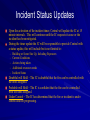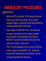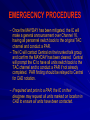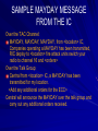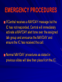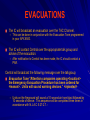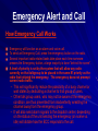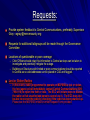
1
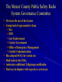
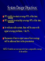
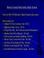
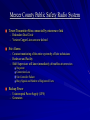
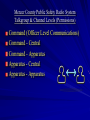
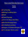
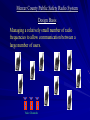
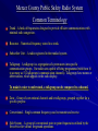
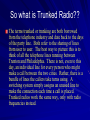
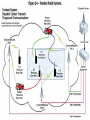
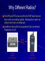
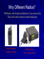
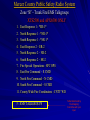
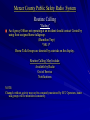
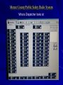
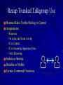
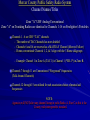
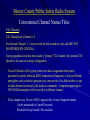
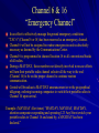
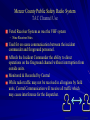
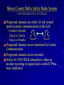
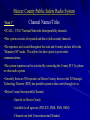
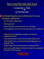
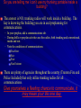
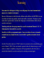
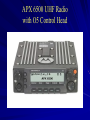
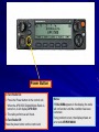
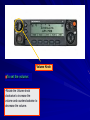
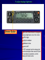
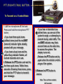
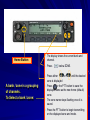
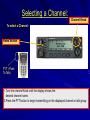
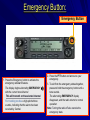
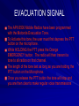
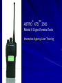
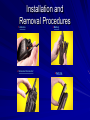
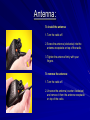
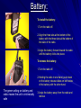
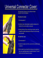
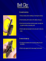
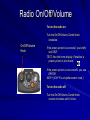
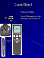
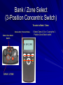
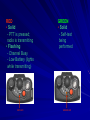
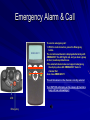
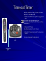
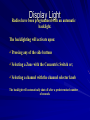
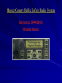
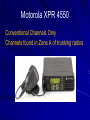
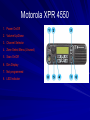
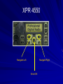
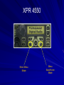
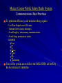
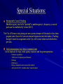
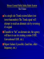
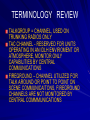
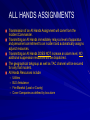
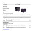
Mercer County Interoperable Public Safety Radio System Trunk Radio System Agency User Training Motorola APX6500 (Mobiles) and XTS2500 (Portables) Motorola XPR4550 (Mobiles) Motorola XPR6350 (Portables) Introductions Class Objectives Upon completion of this training, attendees should have attained An understanding of trunking radio systems. A working knowledge of the Motorola APX6500 Mobile and the XTS 2500 Portables radios. A working knowledge of the XPR 4550 & 6350 radios. The ability to separate Command, Operational and Tactical communications. Understanding of new Radio Procedures and Terminology Design objectives of the radio system: • Enhance personnel safety. • Decrease overcrowding of frequencies. • Increase ability to effectively communicate. • Establish Interoperability between Fire, EMS, PD, Hospitals and other agencies. Factors Prompting Development: Currently, the same frequency is often used for: 1. Dispatch 2. Responding & on-scene communications 3. Requests for additional resources 4. Ground operations In effect…….a party line… Dispatch: Implementation of the new radio system will NOT change dispatch. • Paging - Unchanged • Siren Activation - Unchanged • Station Alerting - Unchanged No change! The Mercer County Public Safety Radio System Governance Committee Oversees the use of the System Comprised of representative from Fire EMS Law Enforcement County Government Office of Emergency Management Central Communications Has adopted SOGs for system use Shall enforce the SOGs Authorizes additional Talkgroups and Radios Final say in disputes with regards to system use System Design Objectives: 95% mobile in-street coverage 95% of the time. 90% portable in-street hip coverage 90% of the time. As with any radio system, there will be areas with signal coverage problems, = the 5% Discussion of how to report areas of low coverage will be addressed later in this presentation. NOTE: Portables are not expected to have comparable coverage to the mobiles. Mercer County Public Safety Radio System Nine site UHF (500 MHz aka T-Band) Trunked radio system. Site Locations Are: Channel 52 Tower Lawrence Twp - Rx/Tx Hightstown Water Tower – Rx/Tx Ewing Police HQ – Rx/Tx (Houses System Redundancy) Hamilton State Police Barracks – Rx Only Trenton Labor and Industry Building – Rx Only Mercer County Corrections Center – Rx Only New Road Tower Hopewell Twp – Rx Only Mt Rose Tower Hopewell Twp – Rx Only Fine Hall Princeton University Campus – Rx Only Mercer County Public Safety Radio System Tower/Transmitter Sites connected by microwave link – Redundant Dual Circle – Verizon Copper Lines are now deleted Site Alarms – Constant monitoring of the entire system by off site technicians – Hardware and Facility – Shift Supervisors will know immediately of troubles at tower sites No power Connection Loss Site Controller Failure Busy Signals and Number of Registered Users Backup Power – Uninterrupted Power Supply (UPS) – Generators Mercer County Public Safety Radio System Talkgroup & Channel Levels (Permissions) Command (Officer Level Communications) Command - Central Command - Apparatus Apparatus - Central Apparatus - Apparatus Mercer County Public Safety Radio System Features Voice Recording Inhibiting/Un-inhibiting Radios Failsoft Dynamic Regrouping Unit to Unit Calling (Limited Basis) Short Radio Messaging (Future) Unit Identification and aliases Emergency Call (Mandown/Emergency ID) AVL (Automatic Vehicle Location) Mercer County Public Safety Radio System Design Basis Managing a relatively small number of radio frequencies to allow communication between a large number of users. 1 2 3 Voice Channels Mercer County Public Safety Radio System Common Terminology Trunk - A bank of frequencies designed to provide efficient communications with minimal radio congestion. Resource – Numerical frequency stored in a trunk. Subscriber Unit – A radio registered in the trunked system. Talkgroup - A talkgroup is a segregation of system users into specific communication groups. Our radios are capable of being programmed with from 16 to as many as 512 talkgroups (communication channels). Talkgroups have names or abbreviations, which appear on the radio display. To make it easier to understand, a talkgroup can be compared to a channel. Zone – Group of conventional channels and/or talkgroups, grouped together for a specific purpose. Conventional – Single common frequency used to transmit and receive. Side System – A group of conventional point to point frequencies utilized by the fire service for various fireground operations. So what is Trunked Radio?? The terms trunked or trunking are both borrowed from the telephone industry and date back to the days of the party line. Both refer to the sharing of lines from user to user. The best way to picture this is to think of all the telephone lines running between Trenton and Philadelphia. There is not, even to this day, an individual line for every person who might make a call between the two cities. Rather, there is a bundle of lines the callers take turns using. A switching system simply assigns an unused line to make the connection each time a call is placed. Trunked radios work the same way, only with radio frequencies instead. So what is Trunked Radio?? What’s Happening Behind the Scenes Once powered on radios are in constant communication with the system via a control channel. A trunked radio system stores a number of frequencies that lay in waiting (trunk). Upon request for a voice transmission the system automatically selects and switches radios to a specific idle frequency. When a voice call is initiated, the system automatically chooses an idle frequency, assigns it to your radio as well as all other radios registered to that talkgroup to receive your transmission. Transmissions are broadcasted over all three tower locations to ensure adequate coverage. Why Different Radios? The APX and XTS series are still in the UHF band, however these radios are trunking capable. Meaning these radios can transmit and receive on talkgroups. In addition, these radio are programmed with conventional frequencies as well. $2000 $2500 APX 6500 MOBILE XTS2500 PORTABLE Found in all Rigs Company Officers Why Different Radios? XPR Radios, both Portable and Mobile are Conventional Only. These radio cannot transmit on trunked talkgroups. XPR6350 Portable XPR4550 Mobile “Firefighters’ Portable” Found in Chiefs’ Vehicles Mercer County Public Safety Radio System Channel Zones Trunking Radios Only Three Zone Configuration Zone A: Conventional TAC and Fire Ground Channels Zone B: Trunked Fire & EMS Talk Group Zone C: UCALL/UTAC/IOPS (Statewide/National & Countywide Interoperability Channels) NOTE: SYSTEM MOBILES AND PORTABLES WILL BE CONFIGURED WITH THE ZONE LETTER PRECEEDING THE CHANNEL NAME. Mercer County Public Safety Radio System Zone “B” - Trunk Fire/EMS Talkgroups XTS2500 and APX6500 ONLY 1. East Response 1 - *ER-1* 2. North Response 1 - *NR-1* 3. South Response 1 - *SR-1* 4. East Response 2 – ER-2 5. North Response 2 – NR-2 6. South Response 2 – SR-2 7. Fire Special Operations - SPC OPS 8. East Fire Command – E CMD 9. North Fire Command – N CMD 10. South Fire Command – S CMD 11. County Wide/Fire Coordinators - CNTY WD 5 - EMS TALKGROUPS To Be Determined by Fleetmapping Committee with your input. Mercer County Public Safety Radio System Routine Calling “Hailing” An Agency/Officer not operating at an incident should contact Central by using their assigned home talkgroup. (Hamilton Twp) *SR-1* Home Talk Groups are denoted by asterisks on the display. Routine Calling May Include: Available by Radio Out of Service Notifications NOTE: Channels without activity may not be constantly monitored by ECC Operators, home talk groups will be monitored constantly. Mercer County Public Safety Radio System What a Dispatcher looks at: Mercer County Public Safety Radio System Response Zone B on Trunking Radios Once dispatched (unchanged) agencies will communicate on their primary or “home” trunk talkgroup for the duration of the incident. *Unless directed by ECC to an alternate talkgroup. This will be done at the end of the dispatch. This talkgroup will remain the primary talkgroup for the duration of the incident. During periods of heavy radio traffic, an alternate talk group and TAC Channel can be assigned by the ECC or may be requested by the IC. If there is a need to change TAC channels, Central will also broadcast that information as well. Example: Station 23, Lawrence Twp 123 Any Street, a Carbon Monoxide Alarm, Operate North Response 2, Channel 4 <repeated> Talkgroup Rig/Officer Portable Conventional Channel Firefighters’ Portable Recap Trunked Talkgroup Use Routine Radio Traffic/Hailing to Central Assignments – – – – – Response On scene and Scene size up IC to Central IC to Incoming Apparatus/Units Units Returning Mobile to Mobile Portable to Mobile Certain Command Functions Mercer County Public Safety Radio System Channel Names/Titles Zone “A” UHF Analog/Conventional Zone “A” on Trunking Radios are identical to Channels 1-16 on Firefighter’s Portables Channels 1 - 6 are UHF “TAC” channels – The number of TAC Channels has now doubled – Channels 6 and 16 are reserved as a MAYDAY Channel (More to Follow) – Home conventional Channels 1, 2, & 3 align with the 3 Home talkgroups – Example: Channel 1 in Zone A (TAC 1) is Channel 1 (*ER-1*) in Zone B. Channels 7 through 11 are Unmonitored “Fireground” frequencies (Talk Around Channels) Channels 12 through 15 are utilized for sub association choice of mutual aid frequencies NOTE: Agencies will NOT alter any channel lineup in radio Banks A, B or C as this is the County wide interoperable standard. Mercer County Public Safety Radio System Conventional Channel Names/Titles TAC Channels TAC Channels are Channels 1-6 Fire Ground Channels 7-11 are reserved for talk around use only and ARE NOT MONITORED BY CENTRAL Each geographical zone has been issued a “primary” TAC channel, this primary TAC channel is the same as existing configuration. - Tactical Channels will be given priority for those assignments that require personnel to operate within an IDLH (Immediately Dangerous to Life and Health) atmosphere such as interior operations at a structure fire, Haz-Mat incident, or any incident deemed necessary by the incident commander. Companies operating at a NON IDLH atmosphere will be moved to a different channel. - These channels are Receive ONLY supported by Central. Supported means: Can be monitored by Central Personnel Recorded to keep record of the incident Channel 6 & 16 “Emergency Channel” In an effort to effectively manage fireground emergency conditions “TAC 6” (Channel 6 or 16) has been reserved as an emergency channel. Channel 6 will not be assigned to routine emergencies unless absolutely necessary as deemed by the Communications Center. Channel 6 is programmed in channel location 16 in all conventional banks of all radios. During a MAYDAY, those members not directly involved in rescue efforts will turn their portable radio channel selector all the way to the end (Channel 16) to be on the proper channel to continue routine communication. Central will broadcast a MAYDAY announcement over the geographical talkgroup, ordering incoming companies to switch their portable radios to Channel 16 upon arrival. Example: (MAYDAY Alert tones) “MAYDAY, MAYDAY, MAYDAY, attention companies responding and operating 123 Any Street switch your portable radios to Channel 16 and stand by, a MAYDAY has been declared.” Mercer County Public Safety Radio System TAC Channel Use Voted Receiver System as was the VHF system – Nine Receiver Sites Used for on scene communication between the incident commander and fireground personnel. Affords the Incident Commander the ability to direct operations on the fireground channel without interruption from outside units. Monitored & Recorded by Central While radio traffic may not be received in all regions by field units, Central Communication will receive all traffic which may cause interference for the dispatcher. Mercer County Public Safety Radio System UHF FIREGROUND CHANNELS Fireground channels are strictly for talk around (point-to-point) communications in the field – Portable to Portable – Vehicle to Vehicle – Vehicle to Portable Fireground channels are not monitored by Central Communications Fireground channels are not recorded Perfect for NON IDLH atmospheres where no incident recording is required and a stable ICP has been established. Mercer County Public Safety Radio System “Bank C” Channel Names/Titles •UCALL / UTAC National/Statewide Interoperability channels. •This system consists of repeated and direct (talk around) channels. •The repeaters are located throughout the state and Country and are left in the “Repeater Off” mode. This allows for direct point to point radio communications. •The system repeaters can be activated by contacting the County ECC by phone or other radio system. •Currently there are NO repeaters in Mercer County, however the NJ Strategic Technology Reserve (STR) has portable repeaters that can be brought to us. •Mercer County Interoperable Channels - Specific to Mercer County - Available to all agencies (POLICE, FIRE, EMS, OEM) - Channels are both Conventional and Trunked Mercer County Public Safety Radio System Channel Names/Titles Bank C UCALL - This channel is NOT monitored at the County ECC. However, the system can be used to manage communications at a large multi-discipline and/or multi-jurisdictional event. System activation shall be requested by the Incident Commander, Fire/EMS Deputy Coordinator or COML (Communications Unit Leader) at the scene of an incident. Mercer County Public Safety Radio System Conventional vs. Trunk on a Incident Scene Conventional Frequencies are an excellent resource for on-scene multi-agency communications. – – – – Safe “line of sight” communications. Off the trunked “grid” The more man power on the scene, the more “ears” are listening. Are not dependant on tower sites for on scene personnel to receive transmissions Trunked system are still dependant on reaching a tower location for transmissions to be heard. Trunk system should not to be used for on-scene interior operations. (EG: Interior Ops, RIT) unless a specific Special Operations Talkgroup has been assigned by Central. Trunked channels can be used inside structures if circumstances dictate, however users should be familiar with the type of structure they are transmitting from and how it affects broadcasts. Training is Key. So you are telling me I can’t use my trunking portable inside a building? The answer is NO, trunking radios will work inside a building. The key is knowing the building you are in and preplanning for communications. – In your preplan, add a communications tab. – During drills or preplan activities use the radios, both trunking and conventional, inside and out. – Note the conditions of communications: Excellent Fair Poor Non Existent There are plenty of agencies throughout the country (Trenton Fire and Police Included) that only utilize trunking radios for all communications. Give yourselves a fleeting chance to communicate, it may mean your life one day. Scanning Scan cannot be relied upon to bridge across talkgroups for normal communication purposes in a trunked environment. Because of the manner in which the radios affiliate and de-affiliate with MCPSRS, the scan list within each radio only partially controls what traffic is monitored. Proximity to other radios whose operators have selected other talkgroups is what determines which calls are carried on each tower. Trunking radios have been programmed to scan all conventional Channels 1-11. No talkgroups have been added to a scan list. Scan Revert will be a programmed option. Scan revert allows the user to instantly transmit back on a channel that has received traffic regardless of channel selector position. So if the IC has there radio set to *NR-1* and are in scan mode, when a transmission comes across Channel 2 (TAC 2) they can instantly respond to that call without having to switch radios or channel. In addition, a hang time will be programmed to allow the radio to monitor that channel for several seconds prior to entering scan mode again. NOTICE All current frequencies programmed into the new radios (mobile and portable) are licensed solely by Mercer County. Any department wishing to add or utilize additional frequencies not licensed by Mercer County, that said department will obtain there own licensing. Use of that frequency is the sole responsibility of that entity. Questions? APX 6500 UHF Radio with O5 Control Head Power Button To Turn Radio On: 1. Press the Power button on the control unit. When the APX 6500 Digital Mobile Radio is turned on, it will display APX 6500. 2. The radio performs a self check. To Turn Radio Off: Press the power button on the control unit. Notes: If FAIL ##/## appears in the display, the radio will not function until the condition has been corrected. If any problem occurs, the display shows an error code ERROR ##/##. Volume Knob To set the volume: •Rotate the Volume knob clockwise to increase the volume and counterclockwise to decrease the volume. To adjust display brightness: Dimmer Button Press the Dimmer Button to change the display brightness to one of four levels: Off to high High to medium Medium to low Low to off If OFF is selected, both the display light and the backlight will be turned off (used for surveillance operations), but the display will remain active. PTT (PUSH TO TALK) BUTTON To Transmit on a Trunked Mode: 1. Lift the microphone off the hook. Press and hold the microphone PTT button. - If you hear three quick tones (callback tones) and the red XMIT (transmit) indicator lights steadily, proceed with your message. - If you hear a busy tone and the yellow Busy indicator flashes, all trunked channels are in use. 2. Release the PTT button and wait for the three quick tones. Within three seconds of hearing these tones, press and hold the PTT button to transmit your message. - If you hear a intermitent lowpitched tone, you are out of the system's range, or attempting to transmit during radio traffic. The red XMIT indicator may flash several times as the radio tries to access the system. The display turns red. - Release the PTT button and try again when the vehicle is within range of the system. 3. Release the PTT button to receive. Note: Time out timer enabled Zone Select or Change Home Button 1. The display shows the current bank and channel. 2. Press 2. Press either • A bank / zone is a grouping of channels. • To Select a bank / zone: below ZONE. zone is displayed or until the desired 3. Press or the PTT button to save the displayed zone as the new home (default) zone. • The zone name stops flashing once it is saved. 4. Press the PTT button to begin transmitting on the displayed zone and mode. Selecting a Channel: Channel Knob •To select a Channel: Home Button PTT (Push To Talk) 1. Turn the channel Knob until the display shows the desired channel name. 2.Press the PTT button to begin transmitting on the displayed channel or talk group Emergency Button: Emergency Button 1. Press the Emergency button to activate the emergency call/alarm feature. The display begins alternating EMERGENCY with the current zone/channel. This will transmit on the selected channel For trunking modes: a high-pitched tone sounds, indicating that the alarm has been received by Central. 2. Press the PTT button and announce your emergency. 3. To exit from the emergency state altogether, press and hold the emergency button until a tone sounds. The alternating EMERGENCY display disappears, and the radio returns to normal operation. Note: Turning the radio off also cancels the emergency state. EVACUATION SIGNAL The APX 6500 Mobile Radios have been programmed with the Motorola Evacuation Tone. To Activate this tone, the user must first depress the PTT button on the microphone. While HOLDING the PTT press the Orange EMERGENCY button. The radio will then transmit a tone to all radios on that channel. The length of the tone last as long as you are holding the PTT button on the Microphone. Once you release the PTT button the tone will stop and you are then clear to make regular voice transmissions ® TM ASTRO XTS 2500 Model II Digital Portable Radio Interactive Agency-User Training Installation and Removal Procedures 1.Antenna 2.Universal Connector 3.Battery 4.Belt Clip Antenna: To install the antenna: 1. Turn the radio off. 2. Screw the antenna (clockwise) into the antenna receptacle on top of the radio. 3. Tighten the antenna firmly with your fingers. To remove the antenna: 1. Turn the radio off. 2. Unscrew the antenna (counter clockwise) and remove it from the antenna receptacle on top of the radio. Battery: To install the battery: 1. Turn the radio off. 2. Align the three tabs at the bottom of the battery with the three slots at the bottom of the back of the radio. 3. Angle the battery forward toward the radio until the battery clicks into place. To remove the battery: 1. Turn the radio off. 2. Holding the radio in one hand, push down on the battery release slides on both sides of the battery with the other hand. The green writing on battery and radio means the unit is intrinsically safe 3. Angle the battery away from the radio and remove. Universal Connector Cover: The universal connector cover protects the side connector near the antenna. To remove the cover: 1. Turn the radio off. 2. Carefully insert a flat-bladed screwdriver between the bottom of the cover and the connector. 3. Holding the top of the cover with your thumb, push the screwdriver gently downward and lever the cover away from the radio. To install the cover: 1. Turn the radio off. 2. Insert the hooked end of the cover into the slot above the connector. 3. Rub the ball of your thumb from the top to the bottom of the cover, applying pressure towards the radio. This will flex the cover and snap it into place. Belt Clip: To install the belt clip: 1. Remove battery before installing or removing the belt clip. 2. Hold the battery with the back of the battery facing you. 3. Hold the belt clip with the top facing upward, and align the clip with the slots on the battery back. 4. Slide the belt clip downward into the slots until it clicks into place. 1 2 To remove the belt clip: 1. Pull away the metal tab at the top of the battery clip from the battery. 2. Slide the clip upward until it comes away from the radio. Motorola XTS 2500: Power On/Off Volume Control CONTROL TOP SIDE BUTTONS Zone Selector MEMORY LOCATION 1 (Long Press) HOME TALKGROUP (Short Press) Push-To-Talk (PTT) Button MEMORY LOCATION 2 (Long Press) HOME CNV CH (Short Press) SCAN ON/OFF (Short Press) Channel Select Emergency Radio On/Off/Volume To turn the radio on: Turn the On/Off/Volume Control knob clockwise. On/Off/Volume Knob If the power-up test is successful, you briefly see SELF TEST, then the home display. If enabled, a power-up tone is also heard. If the power-up test is unsuccessful, you see ERROR XX/YY. (XX/YY is an alphanumeric code.) To turn the radio off: Turn the On/Off/Volume Control knob counter-clockwise until it clicks. Signal Strength Direct/ Monitor TalkAround Scan Battery Status Channel Select To select a channel/mode: There are 16 Channels per bank and can be reached by turning the channel knob. Channel Knob A *N R-1* Push-to-Talk (PTT) Bank / Zone Select (3-Position Concentric Switch) To select a Bank / Zone: Zone Letter / Channel Name Bank / Zone Select Switch B SPC OPS BANK / ZONE 1. Select Zone A, B, or C using the 3Position Zone Select switch. RED • Solid - PTT is pressed; radio is transmitting • Flashing - Channel Busy - Low Battery (lights while transmitting) RED LED GREEN • Solid - Self-test being performed GREEN LED Emergency Alarm & Call EMERGENCY To send an emergency call: 1. With the radio turned on, press the Emergency button. The current zone/channel is displayed alternately with EMERGENCY, the LED lights red, and you hear a group of short, medium-pitched tones. If the selected channel does not support emergency, the display shows NO EMERGENCY. Select a channel that does show EMERGENCY. This will broadcast on the channel currently selected Your UNIT ID # will display on the console @ Central & beep until we acknowledge it LED Emergency Time-out Timer The time-out timer turns off your radio’s transmitter. The timer is set for 60 seconds. 1. Hold down the PTT button longer than the programmed time. You will hear a low-pitched warning tone, the transmission will cut off, and the LED will go out until you release the PTT. 2. Release the PTT button. The LED will re-light and the timer will reset. 3. Press the PTT button to re-transmit. The time-out timer restarts. The timer will restart and the LED lights red. LED Push-to-Talk (PTT) Display Light Radios have been programmed with an automatic backlight. The backlighting will activate upon: Pressing any of the side buttons Selecting a Zone with the Concentric Switch or; Selecting a channel with the channel selector knob The backlight will automatically shut off after a predetermined number of seconds. Mercer County Public Safety Radio System Motorola XPR4550 Mobile Radio Motorola XPR 4550 Conventional Channels Only Channels found in Zone A of trunking radios Motorola XPR 4550 1. Power On/Off 2. Volume Up/Down 3. Channel Selector 4. Zone Select Menu (Unused) 5. Scan On/Off 6. Dim Display 7. Not programmed 8. LED Indicator XPR 4550 Navigate Left Navigate Right Enter/OK XPR 4550 Enter Menu Mode Menu Back/Home Mode Questions? Mercer County Public Safety Radio System Communications Best Practices To optimize efficiency and minimize busy signals – – – – – Use Plain English-avoid 10 codes Transmit short concise messages Avoid lengthy / unnecessary communications Avoid slang, acronyms or codes DIMWIT Does It Matter What I’m Transmitting User of the system are to follow the SOGs/SOPs set forth by the Governance Committee. Speaking of Best Practices Remote Speakers and Microphones Persons using remote speaker microphones should hold the microphone 2”-3” from your mouth and speak directly into the microphone. Vocoders (Voice Encoders device used to analyze/synthesize and reproduce human speech) cannot translate background noise. Attempts should be made to transmit in areas with little to no background noise. Talking “across” mics will lead to low reception volume for listeners. Personnel wearing SCBA masks should hold the microphone directly in front of the voice emitter, not the electronic voice amplifier as these are intended for face to face conversation. Special Situations: Interoperable Console Patching Should an agency need to be “patched” to another agency’s frequency, a console patch can be established by Central (ECC). The City of Trenton is not joining our new system, attempts will be made to have them program some if not all of our conventional frequencies into their radios. Patching through Central for assignments in the City will be more robust and reliable then previous. Field Communications Unit / Mobile Command Center Can be deployed for large, multi agency responses and long term operations. o o o o o o Numerous capabilities TX/RX on all Talkgroups and Channels Patching ICRI Device Brings a dispatcher to the scene of the incident Allows for the ECC to handle other County Incidents Mercer County Public Safety Radio System Failsoft This will appear on the radio display in the event the repeater site that the radio is currently affiliated to experiences a fault with the local site controller computer. The Failsoft feature allows the radio to continue to operate, but in a limited communication mode. – This condition is very rare, but in the event the site goes into Failsoft, a soft beep will repeat every 10 seconds until the affected site controller is restored. During this time, if a transmission is made, the Failsoft beep will not be heard. All communications are limited to the range of the nearest tower. While in Failsoft, your radio will transmit and receive on a predetermined frequency on a conventional channel as opposed to a trunked mode. When the site returns to normal operation, the radio will automatically leave Failsoft operation and return to trunked operation. Mercer County Public Safety Radio System Site Failure In a single site Trunk system failure (one tower/transmitter)-The Trunk signal will attempt to reach an alternate site by reversing it’s signal. If unable to “hit” an alternate site, the agency will have to use its existing system (VHF, Conventional UHF, etc.) Report failure if possible. (land line, other frequency, etc.) Questions? TERMINOLOGY REVIEW TALKGROUP = CHANNEL, USED ON TRUNKING RADIOS ONLY TAC CHANNEL - RESERVED FOR UNITS OPERATING IN AN IDLH ENVIROMENT OR ATMOSPHERE, MONITOR ONLY CAPABILITIES BY CENTRAL COMMUNICATIONS FIREGROUND – CHANNEL UTILIZED FOR TALK AROUND OR POINT TO POINT ON SCENE COMMUNICAITONS, FIREGROUND CHANNELS ARE NOT MONITORED BY CENTRAL COMMMUNICATIONS ALL HANDS ASSIGNMENTS Transmission of an All Hands Assignment will come from the Incident Commander. Transmitting an All Hands immediately relays a level of apparatus and personnel commitment to an incident and automatically assigns adjunct resources. Transmitting an All Hands DOES NOT increase an alarm level, NO additional suppression resources will be dispatched. The geographical talkgroup as well as TAC channel will be secured for only that incident. All Hands Resources include: – – – – Utilities BLS Ambulance Fire Marshal (Local or County) Cover Companies as defined by box alarm Incident Status Updates Upon the activation of the incident timer, Central will update the IC at 15 minute intervals. This will continue until the IC requests it cease or the incident has been mitigated. During the timer update the IC will be responsible to provide Central with a status update, this will include but is not limited to: – – – – – Building or Scene Size Up, Including Exposures Current Conditions Actions being taken Additional resources needs Incident Status Doubtful will Hold – The IC is doubtful that the fire can be controlled with the units assigned. Probable will Hold – The IC is confident that the fire can be controlled with the units assigned. Under Control – The IC has determined that the fire or incident is under control and not progressing. EMERGECNCY PROCEDURES MAYDAYS – While the ECC will monitor TAC channels that have activity in an IDLH environment, the IC or their designee needs to accept the overall responsibility for monitoring radio traffic on the scene. – Upon receipt of a MAYDAY, the IC will confirm all necessary information and then make a general announcement on the operating channel that a MAYDAY has been transmitted and all personnel switch their radios to Channel 16. – The IC or their designee will then contact Central to confirm receipt of the MAYDAY call. Central will broadcast the appropriate announcement over the corresponding Response talk group. EMERGECNCY PROCEDURES – Once the MAYDAY has been mitigated, the IC will make a general announcement over Channel 16, having all personnel switch back to the original TAC channel and conduct a PAR. – The IC will contact Central on the trunked talk group and confirm the MAYDAY has been cleared. Central will prompt the IC to have all units switch back to the TAC channel and to conduct a PAR if not already completed. PAR finding should be relayed to Central for CAD notation. – If required and prior to a PAR, the IC or their designee may request all units marked on location in CAD to ensure all units have been contacted. SAMPLE MAYDAY MESSAGE FROM THE IC Over the TAC Channel: MAYDAY, MAYDAY, MAYDAY, from <location> IC, Companies operating a MAYDAY has been transmitted, RIC deploy to <location> fire attack units switch your radio to channel 16 and <orders> Over the Talk Group: Central from <location> IC, a MAYDAY has been transmitted for my location. <Add any additional orders for the ECC> Central will announce the MAYDAY over the talk group and carry out any additional orders received. EMERGENCY PROCEDURES If Central receives a MAYDAY message but the IC has not responded, Central will immediately activate a MAYDAY alert tone over the assigned talk group and announce the MAYDAY and ensure the IC has received the call. Normal MAYDAY procedures as stated in previous slides will take then place from the IC. MAYDAY AUDIO EVACUATIONS The IC will broadcast an evacuation over the TAC Channel. – This can be done in conjunction with the Evacuation Tone programmed in your APX 6500. The IC will contact Central over the appropriate talk group and advise of the evacuation. – After notification to Central has been made, the IC should conduct a PAR. Central will broadcast the following message over the talkgroup; Evacuation Tone “Attention companies operating <location> the Emergency Evacuation Procedure has been ordered for <reason>. Units will sound warning devices.” <repeated> – Units on the fireground will sound a 10 second air horn blast followed by 10 seconds of silence. This sequence will be completed three times in accordance with N.J.A.C 5:27-2.7. - Emergency Alert and Call How Emergency Call Works Emergency will function as an alarm and voice call. To send an Emergency Call, press the emergency button on the radio. Several important radio related tasks take place each time someone presses the Emergency button, a large majority is done “behind the scene”. A level of priority is set by the system that will allow any radio currently on that talkgroup to be placed in the same #1 priority as the radio that initiated the emergency. The emergency does not preempt current radio traffic. – This will significantly reduce the possibility of a busy channel or wait states by dedicating a channel to that group of users. – Other talk group users, who may not be aware of the emergency condition, are thus prevented from inadvertently wrestling the channel away from the emergency group. – It will also send alarm signals to the dispatch center, depending on the status of the unit sending the emergency (on scene vs. idle) will dictate how the ECC responds to the call. Requests: Provide system feedback to Central Communications, preferably Supervisor Gray - [email protected] Requests for additional talkgroups will be made through the Governance Committee Locations of questionable or poor coverage – Chief Officers should relay this information to Central as steps can be taken to investigate and potentially mitigate the outage. – Buildings or Structures with limited or poor communications should be reported to Central as so valid addresses can be placed in CAD and flagged. Lost or Stolen Radios – In the event a radio programmed to operate on MCPSRS is lost or stolen, the host agency shall immediately contact Central Communications (609799-0110) to report the theft or loss. The ECC will initiate steps to disable the radio so that unauthorized persons cannot use it. The ECC may also be able to recover the radio by checking if the radio has been powered up. Please see the MCPSRS Inhibit/Un-inhibit Request Form provided. Questions? Thank you for your time.