1
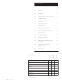
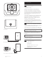
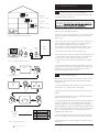
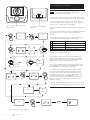
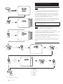
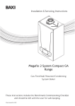
Installation & User’s Instructions
1
24
2
3
21
AUTO
3
°C
6
18
4
5
9
15
6
12
7
MODE
MENU
720644801 shown
Part No. 720644701 7 day Wired Digital Programmer & Room Sensor
Part No. 720644801 7 day Wireless Digital Programmer & Room Sensor
Part No. 720644901 24hr Wireless Digital Programmer & Room Sensor
Please keep these instructions in a safe place. If you move house, please hand them over to the next occupier.
c Baxi Heating UK Ltd 2011
B
1.0 Contents
Page
2.0
Introduction
3
3.0
Programmer & Room Sensor Functions
4
4.0
Installation & Wiring
5
5.0
Wireless Room Unit
7
6.0
Manual Synchronization
of Wireless Units
8
7.0
Standby & Operating Mode
9
8.0
Central Heating & Domestic Hot
Water activation
10
9.0
Temperature Settings
11
10.0
Setting the Time & Day
12
11.0
Setting Central Heating & Domestic
Hot Water
13
12.0
Programmer & Room Sensor
Parameter Codes
14
13.0
Error Codes
15
Kit contents
720644901
2
720644801
Contents
720644701
1.0
Programmer & Room Sensor - 7 day Wired
1
-
-
Programmer & Room Sensor - 7 day Wireless
-
1
-
Programmer & Room Sensor - 24hr Wireless
-
-
1
Receiver
-
1
1
Batteries (AA/LR6)
-
2
2
Fixing Screws
2
4
4
Rawlplugs
2
4
4
Instructions
1
1
1
Table 1. Kit contents
2
c Baxi Heating UK Ltd 2011
2.0 Introduction
1
24
2
3
21
AUTO
2.1
3
°C
1. Specification of Units.
5
9
15
6
12
720644701 7 day Wired (for use with Neta-tec &
Duo-tec) is wired directly to your boiler unit (Fig. 3).
7
MODE
General Introduction
4
6
18
720644801 7 Day Wireless & 720644901 24h Wireless
(for use with Neta-tec, Duo-tec & Megaflo Compact) are
operated remotely via radio frequency wireless transmission to a Radio Frequency Receiver fitted close to the
boiler unit (Fig. 4).
MENU
Fig. 1 Programmer & Room Sensor (720644801 shown)
2. The sensor constantly monitors the temperature of the
room in which it is installed. It can be operated in four
temperature modes, ‘Hi’ (or ‘COMFORT’), ‘Lo’ (or
‘REDUCED’), ‘Frost Protection’, or left in ‘Automatic’
(AUTO) to operate as programmed.
3. Depending on the settings, the boiler will run the ‘Hi’
COMFORT settings during a heating demand and the ‘Lo’
REDUCED setting for overnight periods or times when the
property is left unoccupied.
2.2
Wireless versions (720644801 & 720644901)
1. The units require 2 AA type alkaline batteries (Supplied).
Installation of the batteries is shown in Fig. 12.
2. If the battery symbol is seen flashing in the digital display
(Fig. 5) the batteries need replacing. See Fig. 12 for details.
Fig. 2 Receiver
NOTE: If the batteries are left flat the unit will only retain
its settings for a maximum of one week.
3. The batteries have a lifespan of approximately 2 years.
Batteries should be changed within this timescale as a
precaution.
Boiler
Unit
1
24
2
3
21
AUTO
3
°C
6
18
NOTE: If the batteries are flat the boiler will return to a
default setting of Boiler ON.
4
5
9
15
6
12
7
4. The Clock Function will need to be checked every time
the batteries are replaced.
MENU
MODE
2.3
Technical Specifications
Insulation Class II
Fig. 3 Programmer & Room Sensor - Wired version
IPX Rating IP44
Operating Temperature -5°C to 50°C
2
3
21
Boiler
Unit
1
24
AUTO
3
°C
6
18
4
5
9
15
Transmission Frequency 868MHz
(Wireless only)
6
12
Receiver
7
MODE
MENU
Fig. 4 Programmer & Room Sensor - Wireless version
c Baxi Heating UK Ltd 2011
3
3.0 Programmer & Room Sensor Functions
3.1
Description of Functions
Programme
and Time
Segments
STANDBY
Manual Mode
Current Day
(1 = Monday)
(7 day version only)
1
Automatic Mode
24
2
3
21
COMFORT Mode
AUTO
REDUCED Mode
3
°C
18
6
Current Time
4
Measured
Temperature
5
Domestic Hot
Water
9
15
6
Battery life
(Replace if flashing)
12
7
Central Heating
Burner ‘ON’
Indicator
Communication
(Wireless only)
MENU
MODE
Menu Button
Mode Button
Selector Button
Fig 5. Programmer & Room Sensor front view with functions
Symbol
Meaning
MENU
Press the
MENU
Button
MODE
Press the
MODE
Button
Symbol
Meaning
1
Day of
the week
1= MON
(7 day only)
Rotate the
Selector
Button
Standby
selected
Press the
Selector
Button
Central
Heating
Time
Table 2 Programmer & Room Sensor symbols & meanings
4
c Baxi Heating UK Ltd 2011
(flashing = selected)
°C
Temperature
(flashing = selected)
Meaning
Domestic
Hot
Water
(flashing = selected)
Day of
the week
selected
(7 day only)
1
(flashing = selected)
Symbol
Signal
Strength
(flashing = no
signal)
AUTO
Boiler runs
using User
defined
times
Boiler in
REDUCED
Mode
Boiler in
COMFORT
Mode
4.0 Installation & Wiring
1
2
4.1
Programmer & Room
Sensor Backplate
Boiler Wiring
Terminal M2
Low
Voltage
Terminal
Block
1 2 3
Installation
720644701 7 day Wired
1. This Programmer & Room Sensor will take full control of
the boiler once fitted. All the boiler functions are
transferred to the Programmer & Room Sensor except
Chimney, Commissioning and the Combustion Adjustment
functions (Refer to the Boiler Instruction Manual).
2. The boiler must be fully commissioned before fitting this
Programmer & Room Sensor.
Boiler
Mains
Voltage
Terminal
Block M1
IMPORTANT !
When fitting Low
Voltage Controls
remove the Yellow Link Wire
from the Boiler Terminal Block M1
NOTE: Communication between the boiler and the
Programmer & Room Sensor can take up to 2 minutes to
establish. During this time, the boiler may attempt to fire
prior to communication being established.
3. If necessary, control can be transferred back to the
boiler. Either remove the unit from its cradle, or remove
the plug from the Receiver, then turn the power to the
boiler off and back on.
4.2
Fig 6. Wiring details for 7 day Wired
720644701
Connecting 720644701 7 day Wired
NOTE: The yellow link wire across terminals 1 & 2 on
the Boiler terminal block ‘M1’ must be removed when
fitting this Low Voltage control system. Fig. 6.
Rear Tab
1. Power down the boiler.
2. Remove the backplate from the unit by pressing down
on the rear tab and easing apart. Fig. 12.
3. Identify a suitable site to locate the Programmer & Room
Sensor. See Fig. 8 for guidance on where to locate the unit.
4. Use a suitable grade of wire when connecting the
Programmer & Room Sensor to the boiler. A specification
of 2 x 0.75mm2 with a maximum length of 50m should be
used.
4. Pass the wires through the access slots in the backplate
and wire the terminals as shown in Fig. 6.
Fig. 7 Connector Pins
5. Screw the backplate to the wall using the fixings provided
and reattach the Programmer & Room Sensor.
6. Turn the power back on.
Min. 200 mm
X
24
3
21
°C
18
24
6
3
21
°C
18
9
15
12
6
MODE
6
9
12
MENU
3
21
12
3
°C
15
X
24
9
15
24
21
18
MODE
MODE
MENU
°C
18
MENU
6
9
15
12
MODE
MENU
1500mm
Fig. 8. Location positions
c Baxi Heating UK Ltd 2011
5
4.0 Installation & Wiring (cont.)
1
2
4.3
Boiler Wiring
Terminal M2
Low
Voltage
Terminal
Block
OT
Connecting 720644801 7 day Wireless &
720644901 24h Wireless.
NOTE: The yellow link wire across terminals 1 & 2 on the
Boiler terminal block ‘M1’ must be removed when fitting
this Low Voltage control system. Fig. 9.
1. The Receiver should be wired to the boiler as shown in
Fig 9.
2. Turn the power to the boiler off.
3. Remove the Receiver backplate by carefully prising it
away from the body. Fig. 10.
OT
IMPORTANT !
When fitting Low Voltage
Controls remove the
Yellow Link Wire from the
Boiler Terminal Block M1
Boiler
Mains
Voltage
Terminal
Block M1
4. Route the wires through the rear of the backplate panel.
If a surface mount is required it will be necessary to break
off the appropriate tabs to give the wire access.
5. Connect the wires to the ‘OT’ connection on the
terminal block. Fig. 9. Note this is removable for ease of
wiring.
6. Connect the other end of the wire to the terminals on
the boiler. Please refer to the boiler manual for wiring
details.
Fig. 9. Receiver Backplate
7. Fix the Receiver to the wall using the fixings provided
and refit the front cover ensuring the correct orientation.
Fig 11.
1. Press Securing Tab.
8. Fit the batteries to the Programmer & Room Sensor.
Fig 12.
2. Ease Backplate away.
Fig 10. Receiver & Access Tab
Fig 11. Completed Receiver
1. Press Securing Tab.
2. Ease away from Backplate.
2 x AA/LR6 Batteries
(Supplied)
Fig. 12. Accessing batteries
6
c Baxi Heating UK Ltd 2011
5.0 Wireless Room Unit
5.1
Boiler & Programmer Communication
24
3
21
°C
18
C
6
9
15
12
MODE
MENU
Example A:
1 floor + 2 walls.
24
3
21
°C
18
B
6
9
15
12
MENU
MODE
Example B:
2 floors + 1 wall.
24
3
21
°C
18
A
6
9
15
12
MODE
MENU
Example C:
3 floors + no walls.
Error
85
1
2
3
21
AUTO
3
°C
6
18
Receiver
4
6
12
7
MENU
MODE
2. If Error codes 83 or 85 are seen during commissioning,
there is a communication problem.
Error
83
4. Error 85 is due to the Programmer & Room Sensor not
communicating with the Receiver. The Programmer &
Room Sensor is either out of range or has not
synchronized correctly. Check the unit’s location (Fig 13)
or proceed to the Manual Sync process in Section 6.0
Boiler
Unit
5. If Error 85 is seen after commissioning, check:
5
9
15
NOTE: Communication between the boiler and the
Programmer & Room Sensor can take up to 2 minutes
to establish. During this time, the boiler may attempt to
fire prior to communication being established.
3. Error 83 is due to the Receiver not communicating with
the boiler. Check the wiring between the Receiver and
boiler. Fig. 9
Fig. 13 Maximum permitted separation
24
1. The units are pre-synced so should communicate with
each other when powered up.
X
a) The Programmer and Room Sensor and the Receiver are
within range of each other. See Fig. 13 and Section 5.2
b) The units are synchronized correctly. Section 6.1.
c) The wiring is correct between the Receiver and boiler.
Fig. 9
Fig. 14 Remote unit Error Codes
6. The maximum distance between the Receiver and the
Programmer & Room Sensor will depend on the layout of
the house. For a typical house, a guideline of 3 floors or
walls can be used, as shown in Fig 13.
HC
1
Hold for 6 seconds
5.2
tSt
OFF
Test for Signal Strength
Before mounting the Programmer & Room Sensor to the
wall, perform the following test to determine the signal
strength. Fig 15.
tSt
OFF
1. Press and hold the Selector Button for approximately 6
seconds and HC 1 will be seen in the display.
2. Rotate the Selector Button until ‘tSt OFF’ is seen in the
display.
3. Press the Selector Button and OFF will flash. Rotate the
Selector Button until ON is seen.
Fig. 15 Signal Strength Test
c Baxi Heating UK Ltd 2011
result
0
1
2
3
4
No Signal
Weak Signal
Poor Signal
Good Signal
Excellent Signal
OK
Up to 8
minutes
test
Retest
tSt
ON
4. Press the Selector Button to start the signal strength test.
The test may last for up to 8 minutes. During this time,
numbers ranging from 0 to 4 are displayed. ‘0’ indicates no
signal available and ‘4’ shows excellent signal strength Fig 15.
Baxi recommends locating the unit to give a signal strength
of 3 or 4. If the signal is low, move the unit to a more
suitable location and retest.
5. Press the Selector Button at any time to interrupt the
test or press MENU to escape once the test has finished.
6. If the Manual Sync. process needs to be carried out see
Section 6.0.
7
6.0 Manual Sync. Function
1
24
2
3
21
AUTO
3
°C
4
6
18
6.1
5
9
15
L1
6
12
L2
7
The Programmer & Room Sensor and the Receiver can be
synchronized using the method shown in Fig. 18 as follows:
MENU
MODE
Synchronizing 720644801 7 day Wireless
& 720644901 24h Wireless
1. Start by setting up the Programmer & Room Sensor.
Press and hold the Selector Button (Fig. 16) for approx. 6
seconds. ‘HC 1’ will be seen on the display.
Fig. 16. Programmer & Room Sensor
Selector Button
Fig. 17. Receiver LED Display
& Button
3. Press the Selector Button and ‘OFF’ will flash. This display
will only remain on the screen for approximately 60
seconds.
SnC
OFF
HC
1
4. Now set up the Receiver. LED ‘L1’ will be flashing. Fig.
18. One of the following conditions will be seen.
Hold for 6 seconds
Go to
Receiver
Unit
SnC
OFF
2. Rotate the Selector Button until ‘SnC OFF’ is seen in the
display.
L1
1 One flash every 2 secs
Boiler and Controller Synchronized.
2 Two flashes every 2 secs
Communication error
3 Three flashes every 2 secs
No communication yet
4 Flash for 1sec
NA for Sync
5 1 sec flash every 1 sec
Synchronization initialisation
See Fig. 27 for detailed description
Rapid Flash
L1
L2
Return
to
Controller
L1
Press &
hold until
slow flash
5. If one flash is seen every 2 seconds, the boiler and
Programmer & Room Sensor are already synchronized.
Return to the Programmer & Room Sensor and press
Menu twice to exit the Synchronization menu.
6. If L1 shows 3 flashes every 2 seconds the units are not
synchronized. Press and hold the Receiver Button until
the rapid flash at L1 changes to a slow flash.
Slow Flash
SnC
ON
SnC
OFF
. . . 4, 3, 2, 1
7. Return to the Programmer & Room Sensor where
‘SnC OFF’ will be flashing. Rotate the Selector Button
until ‘SnC ON’ is seen. Press the Selector Button and
the display shows 4, 3, 2, 1 counting down. When this
process is complete, the unit will display ‘End’ if
synchronization has been successful. Press the Selector
Button to return to the ‘SnC OFF’ screen then press
MENU to escape.
8. If Error 85 is still displayed, the unit hasn’t synchronized
correctly. Return to the beginning and repeat the process.
Err
End
Fig. 18. Manual Sync Process Diagram
8
c Baxi Heating UK Ltd 2011
Reposition
&
Retry
SnC
OFF
MENU
7.0 Standby & Operating Mode
1
1
2
AUTO
3
2
AUTO
°C
4
5
5
6
6
7
7
MENU
MODE
3
°C
4
Fig 19. Unit in Standby Mode.
MODE
MENU
Fig 20. Standby turned off.
1
MODE
2
AUTO
3
7.1
Standby and Operating modes
1. The controller can be set to either Standby Mode or
Operating Mode. In Standby, both the Central Heating and
Domestic Hot Water functions are switched OFF.
2. In Standby the Boiler Frost Protection function is still
activated and will fire the boiler if the temperature in the
boiler drops below 4°C.
3. In Operating Mode, the boiler will respond to any preset
Central Heating or Domestic Hot Water demand.
4. The screen display shows the current settings. Fig 19
shows the unit in Standby Mode. Fig 20 shows Operating
Mode.
4
5
6
7.2
Changing Standby and Operating Mode settings
7
1. To change the unit’s settings, follow the flow diagram
shown in Fig 21.
1
2
AUTO
3
2. Press the Mode button and the Standby symbol will flash
and ‘OFF’ is shown in the main display. The Central Heating
and Domestic Hot Water symbols can also be seen.
4
5
Confirm
6
7
3. Press the Selector Button once and ‘OFF’ will flash. The
Central Heating and Domestic Hot Water symbols
disappear.
4. Rotate the Selector Button clockwise until ‘On’ is seen in
the display.
1
2
AUTO
3
4
5
6
5. Press the Selector Button once to confirm the selection
and then ‘Menu’ to return to the main screen. If Menu isn’t
pressed the display will return to the Main screen after
approximately 2 seconds. The unit is now in ‘Operating
Mode’.
7
AUTO
1
In REDUCED mode, the boiler will maintain a
minimum temperature in the property. If at any time,
day or night, the temperature falls below this value
the boiler will fire until the temperature is achieved.
2
AUTO
3
4
Confirm
In AUTO, the boiler will heat the property to the
temperature set on the i-THINK Controller during
the programmed timed Heating periods
5
In COMFORT, the boiler will constantly heat the
property to the temperature set on the i-THINK
Controller. NOTE: This will continue until the boiler
is taken out of COMFORT mode.
6
7
OFF
Heating or Hot Water set to OFF
COMFORT room temperature
MENU
REDUCED room temperature
To Escape
(or wait 2 secs)
Fig 21. Standby & Operating Mode Diagram
c Baxi Heating UK Ltd 2011
Domestic Hot Water setting
Time
Band
Hourly Central Heating programme
Time
Band
Hourly Domestic Hot Water programme
Table 3. Display Icons
9
8.0 Central Heating & Domestic Hot Water ON
MODE
MODE
8.1
Setting Central Heating to ON
1. Press the MODE button and rotate the Selector Button
until the flashing Central Heating symbol is seen in the
display. Fig. 22.
2. Press the Selector Button once to confirm the setting
and the OFF will flash.
3. Rotate the Selector Button to scroll through the options
available. In Central Heating, these are AUTO, REDUCED,
COMFORT and OFF. Press the Selector Button to confirm
the setting.
4. Press MENU to escape, or wait 3 seconds and the unit
will return automatically to the main display screen.
Confirm
Confirm
OFF
NOTE: A delay during this process will cause the unit to
revert back to the main screen. If this happens the process
must be restarted.
OFF
8.2
AUTO
ON
REDUCED
ECO
COMFORT
OFF
Manual Override of Room Temperature
1. The Room Temperature can be increased or decreased
during a heating period by rotating the Selector Button to
give the required temperature. Press the Selector Button to
confirm the new setting.
2. The set temperature will return to the ‘Comfort’ mode
value at the next heating demand period.
8.3
Setting Domestic Hot Water to ON
1. For Combi boilers it is recommended that the Domestic
Hot Water setting is left in the ‘ON’ position. If it is
necessary to alter the setting follow the process shown in
Fig 22.
OFF
Confirm
Confirm
8.4
MENU
1. If the symbol ‘Sd’ appears in the display please contact
heateam as your boiler may require servicing. The contact
telephone number is shown on the back page.
To Escape
(or wait 3s)
MENU
Service Warning
To Escape
(or wait 3s)
Fig 22. Central Heating & Domestic Hot Water activation
1
1
24
AUTO
3
AUTO
3
4
5
9
6
12
6
12
7 day Wireless
Fig 23. Typical Operating Modes.
c Baxi Heating UK Ltd 2011
4
3
6
18
5
9
15
7
10
AUTO
°C
6
18
2
3
21
°C
6
18
24
2
3
21
°C
15
1
24
2
3
21
5
9
15
6
12
7
7 day Wired
4
7
24h Wireless
9.0 Temperature Settings
MENU
9.1
Setting the Room Temperature (Comfort)
1. To set the Room Temperature, press the MENU button
and SC ON will appear in the display with the current
Room Comfort Set Point shown.
2. Press the Selector Button and the Comfort Set Point will
flash. This set point can be adjusted up or down by rotating
the Selector Button.
SC ON
Sr Ed
Sd HU
3. Press the Selector Button again to confirm the set point
and then press MENU to return to the main display screen.
The Comfort Set Point is now confirmed.
9.2
SC ON
Sr Ed
°C
The Comfort Set Point can be increased or decreased
during a heating period by rotating the Selector Button to
give the required temperature. Press the Selector Button to
confirm the new setting. The set temperature will return to
the previous COMFORT mode value at the next heating
demand period.
Sd HU
°C
Manual Override of COMFORT setting
°C
9.3
Setting the REDUCED Temperature
1. To adjust the REDUCED set point, press the MENU
button and rotate the Selector Button until ‘Sr Ed’ appears
in the display.
+ °C
- °C
2. Press the Selector Button to access the menu. The
current set point will be seen flashing. The set point can be
adjusted up or down by rotating the Selector Button.
3. Press the Selector Button again to confirm the set point
and then press MENU to return to the main display screen.
The REDUCED temperature is now confirmed.
9.4
MENU
1. To set the Domestic Hot Water temperature, press the
MENU button and rotate the Selector Button until ‘Sd HU’
appears in the display.
Fig 24. Temperature adjustment diagram
Example: For a minimum outdoor temperature of -10°C and
a required flow temperature of 80°C, the otC value should
be set to 3.0. For further details please see Outdoor Sensor
Kit - Part No. 720103001
otC Menu Values
6.0
5.0
4.0
9.0 8.0 7.0
Setting the Domestic Hot Water
3.0
2. Press the Selector Button and the current temperature
set point will flash. The temperature can be adjusted up or
down by rotating the Selector Button.
3. Press the Selector Button again to confirm the
temperature and then press MENU to return to the main
display screen.
The Domestic Hot Water temperature is now confirmed.
85
80
9.5
Boiler Flow Temperature
75
Setting the Outdoor Sensor Curve
70
2.0
1. To adjust the Outdoor Sensor value press and hold the
Selector Button for approximately 6 seconds to access the
parameter menu. Rotate the Selector Button until ‘otC’ is
seen in the display and press the Selector Button to access.
65
60
55
ult
Defa
50
e
1.5
Valu
1.0
45
2. Set the required temperature compensation value from
the graph (Fig. 25) by rotating the Selector Button and
pressing to confirm. Press ‘MENU’ until the main screen is
displayed.
40
35
0
30
20
15
10
5
0
-5
Outdoor Temperature
Fig 25. Outdoor Sensor Curve Graph
c Baxi Heating UK Ltd 2011
-10
-15
-20
NOTE: This function can not be set or displayed from the boiler
front panel when the Programmer and Room Sensor Controller
is fitted.
11
10.0 Setting the Time & Day
MENU
10.1
°C
To Set the Time.
1. From the main display screen press MENU and rotate
the Selector Button until the clock is displayed. Fig. 26.
1
2
3
4
5
6
7
7 day version only
2. Press the Selector Button once and the hour will flash.
Rotate the Selector Button to increase or decrease the
time. Press the Selector Button once to confirm the hour
setting. The minutes display will now flash.
3. Rotate the Selector Button to set the minutes and press
the Selector Button once to confirm. The time is now set.
Press MENU until the main screen is displayed.
NOTE: The clock will not update automatically so will
require manual adjustment.
1
2
3
4
5
6
Confirm
7
- hrs
7 day version only
10.2
To Set the Day (720644701 7 day Wired &
720644801 7 day Wireless only).
1. Set the Time as described above. Once the Time is
confirmed by pressing the Selector Button, the day symbols
on the right hand side of the screen will flash.
2. Rotate the Selector Button set the day. Monday = 1,
Tuesday = 2 etc. The current day is shown in a small circle.
Press the Selector Button to confirm.
3. The correct time and day should now be shown in the
display. Press MENU once to return to the main display
screen.
1
2
3
4
5
6
+ hrs
Confirm
- min
+ min
7
7 Day
Version
Only
Confirm
1
2
3
4
5
6
- day
7
MENU
Fig. 26. Setting the Time & Day
12
c Baxi Heating UK Ltd 2011
1 = Monday
2 = Tuesday
3 = Wednesday
4 = Thursday
5 = Friday
6 = Saturday
7 = Sunday
+ day
Confirm
11.0 Setting Heating & Domestic Hot Water
PCH
MENU
PdHU
11.1
Setting the Central Heating
1. Press the MENU button and rotate the Selector Button
until ‘PCH’ is seen in the screen. Fig. 27. Press the Selector
Button once.
7-day version only: Press the Selector Button once and
‘Day 1’ (Monday) will be seen flashing. The display can be
set to either 7 individual days, 5 weekdays and 2 weekend,
or 7 days identical. The 24h version does not have ‘Day’
function displayed.
7 day
24h
1
2
3
4
5
1
2
3
4
5
1
2
3
4
5
6
6
6
7
7
7
2. To set the day sequence, rotate the Selector Button until
the required day is displayed. Press the Selector Button to
confirm.
3. The screen displays the time and the letters ‘Pr’ flashing.
Press the Selector Button again and ‘On 1’ flashes.
(Pr = current setting, Pr1, Pr 2 & Pr 3 are presets).
4. Press the Selector Button again and the time flashes. The
first Timed ‘On’ period can now be set. Rotate the Selector
Button to set the desired Central Heating start time.
00:00
Pr
Preset Programmes
Pr1
Pr2
Pr3
5. Press the Selector Button to confirm and the first timed
‘Off’ period flashes. Use the Selector Button to set the
required off period. Press the Selector Button once to
confirm.
6. Repeat the above process for ‘On 2’, ‘Off 2’, ‘On 3’ and
‘Off 3’ time periods. If only 2 Heating periods are required
set ‘On 2’ and ‘Off 2’ to the same time (e.g. 12:00).
7. After ‘Off 3’ has been set the screen will show the ‘On 1’
time flashing again. If Programming is complete, press
‘MENU’ repeatedly to return to the main display screen.
00:00
On 1
11.2
Setting the Domestic Hot Water
1. Press MENU and rotate Selector Button until ‘PdHU’ is
displayed. Fig. 27. Press the Selector Button to confirm and
repeat the sequence as described above.
OFF
On 2
OFF
On 3
00:00
On 1
00:00
OFF
00:00
On 2
00:00
OFF
00:00
On 3
00:00
OFF
OFF
MENU
Fig. 27. Setting Central Heating & Domestic Hot Water
c Baxi Heating UK Ltd 2011
13
12.0 Parameter Codes
12.1
Programmer & Room Sensor Functions
1. To access the Menu, press and hold the Selector
Button for approximately 6 seconds. The parameters can
be accessed by rotating the Selector Button.
Display
Description
Default
HC
Assigns the Programmer & Room Sensor to heating circuit.
.Ao
Sets the Programmer & Room Sensor as Master (CEn).
rtE
Enables the USER to adjust the reduced room temperature setting
Enabled
dh
Enables the USER to adjust the DHW temperature and hourly programming
Enabled
Sets the DHW mode:
1
CEn
24h: DHW always active
Combi
rEL
CHP: DHW is enabled according to the CH hourly programme
24h
DhP: DHW is enabled according to the DHW hourly programme
oFS
Sets the offset of the room sensor. Used to correct the temperature value read by the
0
sensor if this differs from the actual temperature.
Un
Selects the temperature unit of measurement (°C or °F)
SoFt
Displays the software version
oSt
Not used
N/A
oSp
Not used
N/A
tLr
Not used
N/A
°C
Read only
Enables / Disables room anti-freeze function (from +4° C to reduced room temperature)
ICE
OFF = disabled
4°C
4°C = settable
otC
Sets the kt curve for external weather sensor 720103001 (0.1 – 9.0). (See Section 9.5)
1.5
rtS
Enables (ON) / Disables (OFF) the room sensor.
ON
Mod.
Enables (ON) / Disables (OFF) room temperature modulation.
ON
ULt
Sets the maximum CH flow temperature (Max CH)
85°C *
TSP
Accesses the “Pxx” board parameters menu
---
Snc
Synchronization of Programmer & Room Sensor (720644801 & 720644901) with the boiler.
Refer to Sections 5 and 6 of this manual
TSt
Radio transmission test (WIRELESS only). The function lasts 8 minutes or when the Selector
Button is pressed. The display shows the numbers 1 to 4 (1=25% - 4=100%)
End
To return to the main screen.
* Adjustment is required for Low Temperature or Underfloor heating systems.
Table 4. Parameter codes
14
c Baxi Heating UK Ltd 2011
13.0 Error Codes
Receiver
L1
13.1
Error Codes
1. Some error codes can be reset. If an error code is seen
in the display use the reset procedure to try and remove
the fault. Fig. 29.
L2
2. Press the Selector Button once and rotate immediately
until ‘rSt’ is shown in the display.
L1 Flash
L1 Flash
L1 Flash
Normal
Operation
Wired - No
Communication
between Boiler
& Transmitter
2s
2s
L1 Flash x 2
L1 Flash x 2
3. Press the Selector Button again and the error should
reset. If the error doesn’t reset, consult the boiler manual
for further information.
13.2
L1 Flash x 2
Resetting the ‘sd’ - Service Due Code
1. Press the Selector Button once and ‘000’ will be
displayed.
2. Rotate the Selector Button until ‘015’ is seen is the
display.
2s
Wireless - No
Communication
between Room
Unit & Transmitter
2s
L1 Flash x 3
3. Press the Selector Button once and ‘Service Due’ will
clear. Fig 30.
L1 Flash x 3
2s
L1 Flash x 3
13.3
2s
Parameter
Change
Initialization
Phase between
Transmitter
& Boiler
1s
L1 Flash
1s
1s
L1 Flash
1s
1s
Fig 28. Receiver status indicator LEDs
rSt
Fig 29. Resetting Error Codes
000
Fig 30. Resetting the Service Due Code.
Boiler Control
1. If necessary, control can be transferred back to the
boiler. Either remove the unit from its cradle, or remove
the plug from the Receiver, then turn the power to the
boiler off and back on.
L2 Flash
2s
NOTE: Resetting this function without completing the
required service will invalidate your warranty.
015
09
Gas Valve Connection Cable
15
Gas Valve Fault
20
Central Heating NTC Fault
28
40
Flue NTC Fault
Central Heating Return NTC Fault
55
Calibration Required
109
Pre-circulation Fault
110
Safety Thermostat Operated
117
Primary System Water Pressure Too High
118
Primary System Water Pressure Too Low
125
Circulation Fault (Primary)
128
Flame Failure
130
Flue NTC Operated
133
Interruption Of Gas Supply or Flame Failure
134
Elapsed Time - Gas Valve Open Without Gas
135
Interruption Of Gas Supply (Internal Error)
154
Flow/Return Sensor Temperature Test
160
Fan or Fan Wiring Fault
270
Circulation Fault (Dry Fire)
321
Hot Water NTC Fault
384
False Flame
Programmer & Room Sensor Error Codes (See Sec. 5.1)
83
Error between Boiler & Receiver
Error between Programmer & Room Sensor
85
& Receiver
Table 5. Error Codes
c Baxi Heating UK Ltd 2011
15
1.0 X X X X X X X X X X X
All descriptions and illustrations provided in this leaflet have been carefully
prepared but we reserve the right to make changes and improvements in
our products which may affect the accuracy of the information contained
in this leaflet. All goods are sold subject to our standard Conditions of Sale
which are available on request.
BAXI
A Trading Division of Baxi Heating UK Ltd (3879156)
Brooks House, Coventry Road, Warwick. CV34 4LL
After Sales Service 0844 871 1525 Technical Enquiries 0844 871 1555
Website www.baxi.co.uk
e&oe
Comp No. 720898904 (12/11)
c Baxi Heating UK Ltd 2011