1
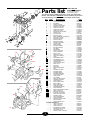
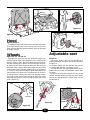
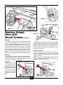
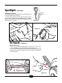
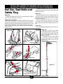
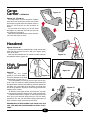
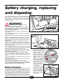
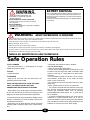
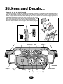
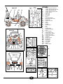
AMAV ENTERPRISES
AMAV
¤¤
TM
OWNER’S MANUAL
FOR MODEL
9539,79529, 9529
IF YOU ENCOUNTER ANY PROBLEMS WITH THE
ASSEMBLY OR FUNCTIONING OF THIS TOY,
DO NOT RETURN IT TO THE STORE
WHERE YOU PURCHASED IT
THEY ARE NOT EQUIPPED TO ASSIST YOU.
CALL THE APPROPRIATE NUMBER BELOW
TO REACH A CUSTOMER SERVICE
REPRESENTATIVE.
AMAV CUSTOMER TOLL FREE:
1-866-395-2628
YOU MUST CHARGE THE BATTERY
FOR 24 HOURS BEFORE FIRST USE
SEE PAGE 10 FOR INSTRUCTIONS.
WARNING
• In the assembly of this toy there are some sharp edges and small parts which
can harm small children. This item also contains electrical items that can be hazardous for children. Please exercise caution in the unpacking of this product.
Children should not handle parts, batteries or take part in the assembly of this
vehicle.
THIS TOY SHOULD ONLY BE
ASSEMBLED BY AN ADULT
• While assembling the vehicle, keep small parts away from children and discard any plastic bags immediately. If at a future date, the batteries have to be replaced, you will need a screwdriver to remove them.
THIS TOY MUST ONLY BE OPERATED
UNDER ADULT SUPERVISION
• Children must be supervised at all times when operating this vehicle. Improper use may lead to serious or
fatal injuries. Children must be shown how to operate the vehicle by an adult, and allowed to use it only after
a parent has determined that they understand all the features of the car. Even then, they must still be supervised at all times.
• Follow all the instructions carefully to ensure that your child operates and enjoys this vehicle as safely as
possible.
• Only use the AMAV Power Rider™ on level surfaces or inclines of less than 60. Stay away from steep slopes
or inclines, stairs, driveways or ramps. Also keep away from any bodies of water or puddles. Do not use in the
dark. Watch out for low hanging obstructions.
• For obvious reasons, this vehicle must never be used on a street or roadway of any kind. Keep off trails used
by off-road vehicles as well.
• This vehicle is designed for two children, maximum weight, 105 lbs. (47.5 kg)
• Shoes must be worn at all times. Never stand in the vehicle.
• The seat belts and roll bar are play features only and are not intended as a substitute for adult supervision.
• Never attempt to repair or change in any way, the electrical system of this vehicle. Tampering and alterations
of any kind can lead to fire or other hazards that could result in serious injury.
• Never hold the batteries by their wires. Lift and carry by the case only. This will avoid the risk of fire or other
injuries from the batteries. (For further warning regarding the batteries, fuses and charger, see page 10.)
IF YOU HAVE ANY QUESTIONS ABOUT THIS PRODUCT, CALL THE APPROPRIATE NUMBER
LISTED IN THIS MANUAL AND A CUSTOMER SERVICE REPRESENTATIVE WILL BE ABLE TO
HELP YOU.
2
GGG
Parts list
THIS IS NOT AN
ASSEMBLY DIAGRAM.
For assembly instructions,
see the following pages.
This parts list applies to AMAV Power Rider™ model 9539, 9529, 79529
Extreme. Parts indicated in UNDERLINE must be installed by the consumer.
The parts marked by *are optional and are not integral with all models.
Key
GGG
FFF
FFF
GGG
GGG
PP
SS
OO
BB
CC
Z
XX
DD
Q
T
MM
EEE
AA
EE
R
F
P
G
YY
AAA
C
A
BBB
FF
E
J1
O
I
L
ZZ
V
M
N
W
J2
J1
QQ
GG
U
O
DDD
J2
JJ
L
CCC
Quan.
DESCRIPTION
9539
.............1 . . . .OWNER’S MANUAL . . . . . . . . . . . . . . . . . . . . . . . BKEXPDE
A...........1 . . . .ACCELERATOR SWITCH . . . . . . . . . . . . . . . . . . . MACSSW1
B...........2 . . . .BATTERIES . . . . . . . . . . . . . . . . . . . . . . . . . . . . . . MBAT12A
C ..........1 . . . .GEAR SHIFT BOX . . . . . . . . . . . . . . . . . . . . . . . . SAGSBX1
.............1 . . . .BATTERY RECHARGER . . . . . . . . . . . . . . . . . . . . SACNA12
D ..........2 . . . .GEAR BOX & MOTOR . . . . . . . . . . . . . . . . . . . . . SAGRBOX
E...........1 . . . .GEAR SHIFT COVER . . . . . . . . . . . . . . . . . . . . . . PLCGSGR
F ...........1 . . . .GEAR SHIFT HANDLE . . . . . . . . . . . . . . . . . . . . . PLCGSHL
G ..........1 . . . .GEAR SHIFT PLATE . . . . . . . . . . . . . . . . . . . . . . . PLCGSPR
H ..........2 . . . .MOTOR SPLASH GUARDS . . . . . . . . . . . . . . . . . PLMSGDC
I ............3 . . . .WIRING CLIPS . . . . . . . . . . . . . . . . . . . . . . . . . . . MEHCLIP
J1 .........2 . . . .ROLL BAR PINS . . . . . . . . . . . . . . . . . . . . . . . . . . MCPLSBP
J2 .........3 . . . .SEAT BELT PINS . . . . . . . . . . . . . . . . . . . . . . . . . MCPLSWP
K...........1 . . . .METAL STEERING COLUMN CLIP . . . . . . . . . . . . MESTCLR
L ...........2 . . . .SEAT BELTS (LONG) . . . . . . . . . . . . . . . . . . . . . . MSBABLK
M ..........1 . . . .SEAT BELT (SHORT) . . . . . . . . . . . . . . . . . . . . . . MSBCBLK
N ..........2 . . . .BUCKLES (MALE) . . . . . . . . . . . . . . . . . . . . . . . . . MSBBMBK
O ..........2 . . . .BUCKLES (FEMALE) . . . . . . . . . . . . . . . . . . . . . . MSBBFBK
.............2 . . . .BATTERY CUSHIONS . . . . . . . . . . . . . . . . . . . . . . MFOMBAT
.............2 . . . .30 AMP FUSES . . . . . . . . . . . . . . . . . . . . . . . . . . . MFUSE30
P...........1 . . . .PEDAL SCREW . . . . . . . . . . . . . . . . . . . . . . . . . . MS11258
Q ..........2 . . . .BATTERY SCREWS . . . . . . . . . . . . . . . . . . . . . . . MS3/4#8
R ..........1 . . . .BATTERY BRACKET . . . . . . . . . . . . . . . . . . . . . . . PLCBATB
S...........1 . . . .CAR BODY . . . . . . . . . . . . . . . . . . . . . . . . . . . . . . PLCBDRD
T ...........1 . . . .DASHBOARD . . . . . . . . . . . . . . . . . . . . . . . . . . . . PLCDBRD
U ..........1 . . . .SAFETY FLAG POLE . . . . . . . . . . . . . . . . . . . . . . PLCFPBK
V...........1 . . . .POLE EXTENSION . . . . . . . . . . . . . . . . . . . . . . . . PLCFEBK
W..........1 . . . .SAFETY FLAG . . . . . . . . . . . . . . . . . . . . . . . . . . . PLFLAGH
X...........1 . . . .FRONT AXLE (LEFT) . . . . . . . . . . . . . . . . . . . . . . PLCFWAL
Y...........1 . . . .FRONT AXLE (RIGHT) . . . . . . . . . . . . . . . . . . . . . PLCFWAR
Z ...........1 . . . .HOOD . . . . . . . . . . . . . . . . . . . . . . . . . . . . . . . . . . PLCHDR1
AA ........1 . . . .INSTRUMENT PANEL . . . . . . . . . . . . . . . . . . . . . . PLCINST
BB ........1 . . . .SIDE MIRROR (LEFT) . . . . . . . . . . . . . . . . . . . . . . PLCLMRD
CC ........1 . . . .SIDE MIRROR (RIGHT) . . . . . . . . . . . . . . . . . . . . PLCRMRD
DD ........7 . . . .LOCKING PINS . . . . . . . . . . . . . . . . . . . . . . . . . . . PLCLPNG
EE ........1 . . . .ACCELERATOR PEDAL . . . . . . . . . . . . . . . . . . . . PLCGPED
FF.........1 . . . .PEDAL PLUG . . . . . . . . . . . . . . . . . . . . . . . . . . . . PLCPEDP
GG .......1 . . . .ROLL BAR . . . . . . . . . . . . . . . . . . . . . . . . . . . . . . PLCRBBK
HH ........1 . . . .REAR AXLE . . . . . . . . . . . . . . . . . . . . . . . . . . . . . PLCRXL2
II ...........1 . . . .AXLE WASHER REAR . . . . . . . . . . . . . . . . . . . . . PLCRXWA
JJ .........1 . . . .SEAT . . . . . . . . . . . . . . . . . . . . . . . . . . . . . . . . . . . PLCDLCG
KK ........1 . . . .STEERING COLUMN . . . . . . . . . . . . . . . . . . . . . . PLCSTCL
LL .........1 . . . .STEERING GEAR . . . . . . . . . . . . . . . . . . . . . . . . . PLCSTGR
MM .......1 . . . .STEERING WHEEL . . . . . . . . . . . . . . . . . . . . . . . . PLCSWBK
NN ........1 . . . .STEERING ASSEMBLY . . . . . . . . . . . . . . . . . . . . . SACRACK
OO .......1 . . . .ELECTRONIC HORN . . . . . . . . . . . . . . . . . . . . . . MELSM4X
PP ........1 . . . .HORN COVER . . . . . . . . . . . . . . . . . . . . . . . . . . . PLCSWCR
QQ .......1 . . . .CAR PHONE . . . . . . . . . . . . . . . . . . . . . . . . . . . . . SAPRTEL
RR ........1 . . . .PEDAL SPLASH GUARD . . . . . . . . . . . . . . . . . . . PLCVPPC
SS ........1 . . . .WINDSHIELD FRAME . . . . . . . . . . . . . . . . . . . . . . PLCWSBK
TT.........2 . . . .FRONT WHEELS . . . . . . . . . . . . . . . . . . . . . . . . . SACFWLB
UU ........2 . . . .FRONT WHEEL HUBS . . . . . . . . . . . . . . . . . . . . . PLCFWCY
VV ........2 . . . .BACK WHEELS . . . . . . . . . . . . . . . . . . . . . . . . . . . SACRWLB
WW ......2 . . . .BACK WHEEL HUBS . . . . . . . . . . . . . . . . . . . . . . PLCRWCY
*XX .......1 . . . .HOOD AIR INTAKE . . . . . . . . . . . . . . . . . . . . . . . . PLCAIRY
*YY .......1 . . . .WINCH/BRUSH GUARD . . . . . . . . . . . . . . . . . . . . PLCPBWY
ZZ.........1 . . . .FOAM HEADREST . . . . . . . . . . . . . . . . . . . . . . . . MEXTFHR
*AAA ....1 . . . .REAR CARGO BASKET FRAME . . . . . . . . . . . . . .PLCBFBK
*BBB ....1 . . . .REAR CARGO NET . . . . . . . . . . . . . . . . . . . . . . .MNETEXT
*CCC ....1 . . . .EXHAUST PIPE (LEFT) . . . . . . . . . . . . . . . . . . . . .PLCSELG
*CCC ....1 . . . .EXHAUST PIPE (RIGHT) . . . . . . . . . . . . . . . . . . .PLCSERG
*DDD ....1 . . . .SPOTLIGHT AND CORD . . . . . . . . . . . . . . . . . . . .SASPOTL
*EEE ....1 . . . .SOUND SYSTEM . . . . . . . . . . . . . . . . . . . . . . . . .MXSOUND
FFF ......2 . . . .AXLE WASHERFRONT . . . . . . . . . . . . . . . . . . . . .PLCWB49
GGG.....6 . . . .LOCK/PIN INSERT . . . . . . . . . . . . . . . . . . . . . . . .PLCLIW
.............4 . . . .EXHAUST PIPE SCREWS . . . . . . . . . . . . . . . . . .MS6X175
.............1 . . . .WINCH HANDLE . . . . . . . . . . . . . . . . . . . . . . . . . . PLCWHAY
.............1 . . . .WINCH HANDLE PLUG . . . . . . . . . . . . . . . . . . . . PLCWHPY
STICKERS AND DECALS
.............1 . . . .HEAD LIGHT-RIGHT . . . . . . . . . . . . . . . . . . . . . . . PSEMIR1
.............1 . . . .HEAD LIGHT-LEFT . . . . . . . . . . . . . . . . . . . . . . . . PSEMIR2
.............1 . . . .WHEEL STICKER . . . . . . . . . . . . . . . . . . . . . . . . . PSEWH12
.............1 . . . .DASHBOARD STICKERS . . . . . . . . . . . . . . . . . . . PSTRUGA
.............1 . . . .SPEAKERS +NO. PLATE . . . . . . . . . . . . . . . . . . . PSTRUGB
.............1 . . . .TELEPHONE+VENT . . . . . . . . . . . . . . . . . . . . . . . PSTRUGL
.............1 . . . .FLAMES ( HOOD + DOORS ) . . . . . . . . . . . . . . . . PSTRFLM
RR
3
“Snap-Fit” Assembly
Sound
Unit
Figure 1
Figure 2
NOTE: If you purchased this car in the
United Kingdom, Republic of Ireland or
Australia, your steering column has
been installed for right-hand drive. The
positions of the horn and steering wheel
will be reversed.
Figure 3
Sound Unit (*OPTIONAL)
and Dashboard
Figures 1 and 2
To install the horn, place the dashboard on a table or other
hard surface as shown above. Line up the notch on the bottom
of the horn with the notch on the hole in the dashboard as
shown in figure 1. Now press down on the dashboard to snap
the horn into place.
Figure 4
Figures 3, 4 and 3
When you take the car and all the parts out of the box, you
will see the body of the car, as shown in Figure 3.
Figure 5
To attach the dashboard to the car, just line up the left hole
with the steering column, and slide the dashboard down. Then
snap it down in front.
Windshield
Figures 6 and 7
Now you can attach the windshield and side mirrors to
the car. As you can see in Figure 6, the windshield and
mirrors slant towards the back of the car when installed.
Be sure to line them up as shown before snapping them
in place.
The windshield posts slide through the holes in the mirror frame, through the dashboard, and snap into the car
body.
Figure 7
Figure 6
4
Figure 10
Figure 9
Figure 11
Figure 8
Hood
Figures 8 and 9
To attach the front hood, just line up the two tabs at the base
of the hood with the slots in the car body, just in front of the
dash. Once the tabs are inserted correctly, the hood will close
for a tight, snug fit.
A
B
Adjustable seat
Wheels
Figure 10, 11, 12 and 13
Slide the front wheel onto the axle as shown in(figure 10).
Take the yellow wheel hub and place it in the wheel well as
shown in figure 11. Now secure the wheel and the hub to the
axle with a locking pin A. Push it into place and give it a quarter twist to secure until it snaps into place.Then take the pin B
and insert it with a quarter twist until it snaps into place. Take
a look at the inside of the back wheels before you slide them
on. There are two notches inside the wheel that must line up
with the tabs on the wheel axle. The easiest way to do this, is
to slide the wheel onto the axle, (figure 12) and twist it slowly
from side to side until it snaps into place. Place the yellow
wheel hub and secure it to the axle with a locking pin A, and
pin B. ( Figure 13 )
Figure 14
Your Power Rider™ seat can be adjusted for a
growing child. It fits into slots in the car body as shown
in Figure 14
For smaller children the seat fits into slots “B” and
“D”,and for taller children, into slots “A” and “C”.
To install the seat, line up the tabs with the appropriate slots in the base, and snap down until it clicks
into place.
To remove the seat, look under the car and you will
see the seat tabs showing through the base. Simply
squeeze the tabs towards the center of the car, and
pull the seat up.
Tabs
Gear box
A
B
Figure 13
Figure 12
5
Figure 14
A B
C D
Locking pin
Sound Unit
(*OPTIONAL)
Figure 16
Figure 15
Steering Wheel,
Horn and
Sound System(*OPTIONAL)
Figure 17
Figure 15
To attach the steering wheel, first make sure that the
wheels are pointing straight. You can move them by hand
if necessary. Now take the steering wheel, and hold it so
that you are facing it. Make sure that the 3 “arms” of the
steering wheel, are positioned at 8 o’clock, 4 o’clock and
12 o’clock (pointing up in the center, and down to the left
and right). Slide the steering wheel on to the steering column in this position. If the arms are not pointing in the right
direction, you can take off the steering wheel and do it
again. Don’t forget to keep the car wheels pointing straight.
Now place the sound system (*optional ) by first sliding
the wire through the other hole on the dash, and then
placing the sound system as you did the round disc .
Make sure that the 4 buttons are on the bottom.In case
your jeep model does not have sound module, cover its
hole with the round disc.
Figures 18 and 19
Take the electronic horn and remove the “tab” on the
bottom. As shown in Figure 18, place it in the steering
wheel hole. Now take the plastic cover, and snap it into
place over the horn.
NOTE: The cover has four flaps that fit over the four buttons on the horn. When placing the stickers, use the
appropriate sticker for each sound.
Figure 16
Now take the locking pin, shown in Figure 16, (there are
5 pieces like this. The other 4 are for the wheels). Place a
locking pin in the hole in the steering wheel, and press
down and turn until it clicks into place.
Figure 17
There is one or two
round disc that covers
the hole to the right of
the steering wheel. It has
a small tab on the edge.
Line this up with the
notch in the hole in the
dashboard, and give it a
slight turn to lock it in
place.
Figure 18
Figure 19
Tab
6
Spotlight
(*OPTIONAL)
Figure 20, 21 and 22
The spotlight should be attached onto the windshield frame
on the same side as the gear shift.
Insert the wires through the hole under the dash and then
turn the car over. Attach both the spotlightand sound system
wires as shown in figure 22. To activate the spotlight, push and
hold the button on the back.
Figure 20
Figure 22
Figure 21
Exhaust
(*OPTIONAL)
Figures 23 and 24
There are two pretend exhaust pipes to install (one on each side).
These are installed on the car body below the door (figure 23).
Line up the exhaust with the holes in the body and fold the screw tab
under as shown in figure 23. Attach the screws, through the exhaust and
into the screw tab.
Figure 23
Figure 24
7
THE ROLL BAR, SEATBELTS AND HEADREST ARE PLAY FEATURES ONLY
AND ARE NOT INTENDED AS A SUBSTITUTE FOR ADULT SUPERVISION.
Roll Bar, Seat Belts and
Safety Flag
To attach the female clip to the long strap, just
slide the strap through, leaving the clip at about the
middle of the strap.
Figure 29
Now slide the end of the long strap through the
hole in the roll bar. There are two holes in the roll
bar. Slide the strap through the roll bar on the same
side as the long strap.
Take the small plastic pin and slide it into the loop
at the end of the long strap. Now pull on the strap
from the front, until it locks in place against the roll
bar.
Figure 25
To attach the roll bar, just line up the four ends with the holes
in the car body and snap it into place.
Figures 26, 27 and 28
Your seat comes with the seatbelts installed, but without the
clips in place. (Figure 26). There are two clips (male and female)
as shown in Figures 27 and 28. Attach the male clip to the short
strap by sliding the strap in and through as shown in Figure 27.
Once the strap is through, pull the clip so that the strap is sitting
tightly in the clip.
Figure 30
Your assembled seat belts will look like Figure 30.
Male clip
goes here
Figure 25
Female
clip goes
here
Figure 31
There are 3 pieces to the HEDSTROM Power Rider™ safety flag. (2
rods and the flag pennant). Take the
larger rod and slide it into the roll bar as
shown in Figure 31.
Then take the second rod and slide
it into the top of the first rod. The flag
pennant then slides on top of the
assembled rods.
Figure 26
Figure 27
Female
clip
Male
clip
Figure 28
Figure 31
Front
Back
Figure 29
Figure 30
8
Cargo
Carrier
Figure 32
(*OPTIONAL)
Figures 32, 33 and 34
The cargo carrier comes in two pieces, a plastic
frame and a net. Hold up the net and you will see
that it has a long side and a short side as shown in
figure 32, This must line up with the frame as
shown.
On the inside of the frame you will see small
tabs (figure 33). Slide the net hooks into each tab
and pull down for a tight fit.
Now take the assembled cargo carrier and hook
it onto the rear of the car body.
Figure 33
Headrest
Figures 35 and 36
You will see on the foam headrest that a small cut has been
made part way through the foam. With your fingers, gently
open up the seam.
Now slide the headrest onto the roll bar so that it looks like
the illustration below. (Figure 36.)
Figure 34
High Speed
Cut-Off
Figure 37
There are two forward
speeds on your Power Rider™.
Figure 35
These are indicated on the Gear
Shift as High (“H”) and Low (“L”).
In the low speed the car will go up to 2.5 mph, and in high,
up to 4 mph. For reasons of safety parents should disconnect
the higher speed, until they feel that their child can operate the
car safely. It is a good idea to do this before your child uses
the car for the first time. Give them a chance to get used to the
handling of the car first.
To disconnect the higher speed, look under the car body
and you will see where the wires connect under the Gear Shift.
Locate the wires shown in Figure 37, and simply disconnect
them. Once your child has shown that he or she can safely
operate the car, and you feel that the higher speed will not
pose a problem, simply reconnect the two wires.
REGARDLESS OF WHAT SPEED YOUR CHILD USES THE
CAR, THEY MUST BE SUPERVISED BY AN ADULT AT ALL
TIMES.
9
Figure 36
A
Figure 37
B
Battery charging, replacing
and disposing
The 6 volt batteries installed in the car must be charged for 24
hours before you use it for the first time. Never leave the
charger plugged in for more than 30 hours. For charging
instructions, see the section below. Read the following warning before proceeding.
WARNING
• Batteries must only be handled by an adult.
• Read all warnings on the battery labels.
• Never allow children to handle or charge the batteries. A
child could be injured by the electricity used in charging a battery. The batteries contains sulfuric acid (electrolyte) and can
cause serious injury if dropped.
• Never carry the batteries by the wires. Always hold the battery by the case.
• Use of the wrong 6 volt batteries could result in serious injury
due to fire or explosion.
• Always ensure that a 30 amp fuse (installed at the factory) is
used.
• Never alter the electrical system of this vehicle in any way.
Alterations could damage the electrical system or cause a fire.
For service, bring your vehicle to an authorized Power Rider™
Service Center.
• Examine the 6 volt batteries, wires, fuses and charger on a
regular basis for damage or excessive wear. If you detect any
problems, do not attempt to use this vehicle, until it has been
properly serviced. Use of a damaged vehicle could result in a
fire causing serious injury.
• Use only AMAV Power Rider™ replacement parts, available
at a Power Rider™ Service Center. To locate the nearest
Service Center, call the telephone number on page 1.
• After charging the battery for the first time, your Power Rider™
battery should be charged 18 hours after each use. Never
charge for more than 30 hours.
• Do not run the batteries completely down before charging.
• Do not store batteries in a discharged condition. If you are not
using the car for a while, charge the batteries at least once a
month.
• Do not store the batteries in temperatures above 750F (240C)
or below -100F (-190C)
• Rechargeable batteries will not last forever. The life of the batteries depends on actual usage.
• Use the charger indoors only (in a well ventilated area).
• Carefully read these battery instructions to obtain the best
battery life. Failure to follow these directions may permanently
damage your battery and may void the warranty.
FRONT OF CAR
Figure 38
Your factory installed batteries are located under here
Figure 39
plug to the female plug. Now plug
the charger into a regular wall
Figure 40
outlet. If this outlet is controlled by a switch, make
sure the switch is “on”.
Male
Make sure that the batPlug
teries are upright during
charging. During the
Female
charging process, the
Plug
charger will become
warm. This is normal.
Once the batteries have
charged disconnect them by
squeezing the sides of the
“male” plug together and gently
pulling them apart. Do
not force them.
Figure 41
Now in the same way
you connected the batteries to the charger,
connect the batteries to
the car wires as shown
in Figure 41. Close the
hood and you’re almost
ready to drive.
Battery Charging
Your factory installed batteries have been tested before they
were shipped. They will have to be charged before you use the
car. Open the hood of the car and you will see the 2 sets of
wires. One set comes out from the battery section, under a special protective plate in the front. (Figure 38). Now take the battery charger. It also has a set of wires. Look at the ends of the
charger wires and the battery wires and you will see “male” and
“female” connectors as shown in Figure 40. Connect the male
10
WARNING
IF BATTERY LEAK DEVELOPS:
BATTERY DISPOSAL
Your 6-volt sealed lead acid battery cannot be disposed of in
your household trash. Place it in a plastic bag. It must be collected and recycled or disposed of in a manner that respects
the environment.
Contact your local environmental agency for disposal options
in your area.
- Avoid contact with leaking battery acid.
- Place battery in a plastic bag, and follow
disposal instructions.
IF ACID COMES INTO CONTACT WITH SKIN
- Flush skin with cold water for at least 15 minutes
- Call a physician
IF ACID IS INGESTED
- Give water, milk of magnesia or egg whites immediately
- Do not induce vomiting
- Call a physician
WARNING
ADULT SUPERVISION IS REQUIRED
Children lack the judgement necessary to avoid injury or accidents. Make sure that the child operating this vehicle understands its function and has demonstrated an ability to drive it safely. They must be supervised at all times.
To avoid damage to the motor and gears, do not allow more than two children to ride in the car at a time.
Maximum total weight: 105 lbs. (47.5 kg.)
Children must wear shoes and remain seated at all times.
The safety belts and roll bar are play features only and are not intended as a substitute for adult supervision.
Improper or careless use of this car may result in a serious injury or fatal accident. Children should only be allowed to operate this car, once a parent has
determined that they understand its operation and can do so safely.
THERE IS NO SUBSTITUTE FOR ADULT SUPERVISION
Safe Operation Rules
• Keep away from bodies of water or puddles.
• Do not drive at night.
• Watch for low hanging obstructions.
• The car may tip when going down a steep slope, or not
be able to stop even when the pedal is released. Avoid
slopes of more than 60. Keep away from stairs, pools,
sundecks.
• Do not operate on gravel or loose dirt, only on smooth,
hard surfaces. Undue strain on the motor will cause
switch, motor or fuse to fail.
• Do not wash car with hose and soap. Use only a clean
damp cloth.
• Never operate vehicle on its side, or turned over.
• The vehicle’s electrical elements (switches, motor, battery, etc) emit an internal spark when turned on. Do not
operate near flammable vapors, such as gasoline,
propane BBQ tanks, paint thinner, etc., to avoid risk of
fire or explosion.
• To prevent unsupervised children from using vehicle,
disconnect or remove batteries when not in use. To
remove the batteries, undo the bracket over the batteries
with a screwdriver, disconnect the plugs, and remove the
batteries. Do not lift by the wires. Store upright.
TO GO FORWARD
- move the Gear Shift to “L”, (Low Speed) or “H” (High
Speed) and press the pedal.
TO STOP
- release the pedal.
TO REVERSE
- Stop the car first, then move the Gear Shift to “R”,
(Reverse) and press the pedal.
HAVE CHILDREN PRACTICE THESE FEATURES
UNTIL YOU ARE SATISFIED THAT THEY
UNDERSTAND THE DIFFERENT FUNCTIONS
While children may quickly master the skills necessary
to drive this vehicle, they do not have the maturity or the
judgement to safely drive it without adult supervision.
• Parents should look at the area that the children will be
driving in, and decide if it is safe. Children cannot make
that decision themselves.
• Keep away from all areas that are used by motorized
vehicles (roads, driveways, parking lots, off-road tracks,
etc.)
11
Stickers and Decals...
Figures 42, 43, 44, 45, 46, 47, ana 48
You are now ready to decorate your car with the sticker and decal sheets. To apply the decals, just peel them off the
sticker and decal sheets, and apply them to the car. Press down firmly, and wipe with a clean dry cloth to remove any
bubbles. To apply the mirror surfaces, cut out the design with a pair of scissors. Cut out an area slightly larger than the
area outlined on the sticker sheet. Peel back one edge and line up the
sticker on the mirror frame. Press down the area you have exposed. Now
pull back the backing as you press down the sticker. (see Figure 43).
Take a look at the illustrations on the this page, and the following page for
the location of your stickers and decals.
A
Figure 42
B
M
Figure 43
L
Vent (N)
Stereo (O)
Fuel &
Temperature
Gauges (S)
Oil &
Volt
Gauges (R)
C
Wipers &
Heater (P)
Vent (N)
Figure 44
Speakers
(BB)
Key
(CC)
Speakers (BB)
Steering
Column
Turn
Signal
(W)
Turn
Signal (W)
Speedometer (T)
12
RPM
(Tachometer)
(U)
Figure 45
I
A
CC
Q
STICKERS
WINCH
BOTTOM
WINCH
TOP
I
G
F
A . . . . .Flames (top part) right side
B . . . . .Flames (bottom part) right side
C . . . . .Flames (top part) left side
D . . . . .Flames (bottom part) left side
E . . . .Flames (hood)
F . . . .Winch (A)
G . . . .Winch (B)
H . . . .Air intake
I . . . . .4 x 4
J . . . .Windshield wipers
K . . . .Brush guard vent holes
L . . . .Speed dial
M . . . .Phone touch pad
N . . . .Vent
O . . . .Stereo
P . . . .Heater
Q . . . .Power Rider
R . . . .Oil
S . . . .Fuel
T . . . .Speedometer
U . . . .RPM (Tachometer)
V . . . .Horn
W . . . .Turn indicators
X . . . .Wheels (front, top)
Y . . . .Wheels (front, bottom)
Z . . . .Wheels (rear, top)
AA . . .Wheels (rear, bottom)
BB . . .Speakers
CC . . .Shifter and Key
DD . . .Safety strip
EE . . . .Rear lights
FF . . . .Front lights
GG . . .Fog lights
HH . . .Mirrors
JJ . . . .Car no. plate
D
E
C
A
E
B
FF
X
Y
B
I
H
Figure 46
J
GG
E
CC
FF
J
U
J
T
W
H
F
G
K
Apply the winch sticker in 2 pieces. Line up the top sticker “F” (red dot at
top) with the top of the winch. Then apply the bottom sticker “G” below it.
Figure 47
P
O
X, Z
L
N N
M
Q
R
Q
S
Y, AA
Figure 48
Y
EE
FF
AA
K
X
GG
Z
DD
DD
JJ
EE
HH
DD
HH
BB
BB
GG
FF
JJ
EE
JJ
13
V
Troubleshooting Guide
PROBLEM
Car doesn’t go
Car only runs for a short time
Back wheels turn in different
directions
POSSIBLE CAUSE
SOLUTION
Batteries need to be charged.
Plug batteries into charger for
18 hours. Never more than 30
hours.
Connections are loose.
Check all wire connections. Make
sure they are tight.
Fuse is blown.
Change fuse with 30 amp fuse,
from an authorized Power Rider™
Service Center. For the center
nearest you, call the customer service number on page 1.
6 volt batteries are dead.
If you have not followed the battery
instructions properly, then your batteries may have run down and cannot be recharged. If you are
unsure, have them checked at a
Power Rider™ Service Center.
Switches are broken.
Your electrical switches may have
become damaged or corroded if
left out in the rain or exposed to
any other moisture. Switches may
also be damaged if there has been
stress on the electrical system
caused by operating the vehicle on
loose sand or gravel. See your
local Power Rider™ Service
Center.
Motor is damaged.
Have car repaired at you local
Power Rider™ Service Center.
Batteries are undercharged.
Plug batteries into charger for
18 hours. Never more than 30
hours.
Batteries will not accept full charge.
Although you may have followed
the instructions carefully, even
rechargeable batteries will not last
forever. The average life of the battery is 1 to 3 years. This of course
depends on how you use the car.
See your local Power Rider™
Service Center for new batteries.
For best results, use only
AMAV Power Rider™
batteries. Remember to recharge
for 18 hours.
Wiring to one of the motors has
been reversed.
Locate the motor on the wheel that
is turning in the wrong direction.
and switch the 2 connections on
that motor.
14
PROBLEM
Car was running but has now
stopped or does not run smoothly.
POSSIBLE CAUSE
SOLUTION
Loose wires and/or connections.
Check all connections and tighten
if loose.
Fuse is blown.
Replace fuse with authorized
replacement part.
Too much weight in the vehicle.
Your Power rider™ car is designed
to carry two children. Total weight
is 105 lbs. (47.5 kg) Do not attempt
to tow anything.
Too much stress on the motor due
to driving conditions.
Avoid inclines of more than 6°. If
conditions are too stressful fuse
may blow. Replace fuse and avoid
stressful conditions.
Loose wires and/or connections.
Check all connections and tighten
if loose.
Motor damage or switch damage.
Call the service number for the
Service Center nearest you.
Loose wires and/or connections.
Check all connections and tighten
if loose.
Motor has a dead spot.
Call the service number for the
Service Center nearest you.
Wrong fuse is being used.
Use only a 30 amp fuse available
from your Power Rider™Service
Center.
Child is switching from forward
to reverse quickly without first
stopping the car.
Review with your child, the proper
way to operate the car.
Grinding noise from gear box.
Gears are broken.
Call the service number for the
Service Center nearest you.
Battery charger is warm during
charging.
This is normal when charging your
batteries. Some chargers will not
get warm. This is not a concern.
No correction is needed.
Batteries sometimes makes a
crackling noise during charging.
This is normal when charging
although it may not happen with
every battery.
No correction is needed.
Batteries do not charge, and
charger is cold.
There is no power to the charger.
Make sure the charger is plugged
into a working outlet, or check if
the fuse has blown. Replace the
fuse or bring your charger to a
Service Center.
Car only works sometimes.
Car needs a “push” to start.
Fuse blows all the time.
15
AMAV ENTERPRISES
AMAV
¤¤
Limited
Warranty
90-DAY LIMITED WARRANTY FOR AMAV POWER RIDER™
6-MONTH LIMITED WARRANTY ON 6 VOLT BATTERIES
that were installed at time of manufacture.
This Limited Warranty covers the AMAV Power Rider™ and the installed 6 volt batteries to the original purchaser against defects in materials and workmanship.
The AMAV Power Rider™ must only be used under adult supervision. In order for this Limited Warranty to apply, such use must be normal
use and does not cover the Power Rider™ nor batteries if damaged by unreasonable use, abuse, misuse, neglect, water damage, improper service, accident or other cause not arising from defects in materials or workmanship.
This Limited Warranty does not cover indirect or consequential damages which are hereby specifically excluded. In the event that your jurisdiction does not allow such an exclusion or limitation, then it shall not apply to you. Laws vary from jurisdiction to jurisdiction.
SAVE YOUR ORIGINAL SALES RECEIPT FOR PROOF AND DATE OF PURCHASE.
If you need service or help with your AMAV Power Rider™ or its batteries during the warranty period, call the Customer Service Department
at the customer service number at the bottom of this page, for the name of the Authorized Service Center nearest you.
DO NOT RETURN YOUR POWER RIDER™ TO THE STORE WHERE YOU BOUGHT IT.
They are not equipped to help you...PLEASE PHONE US. The Warranty Registration Card below must be filled out and mailed to the address
below within 10 days of purchase to validate the limited warranty.
LIMITED WARRANTY REGISTRATION CARD
Please fill out and return this card to validate your Warranty
Model Name
Model Number
Name
Address
City
Bought for
State
Male
Female
Zip
Child’s Age
Date of Purchase
Bought at: (store name)
Bought by: Mother
Father
Mother & Father
Grandparent
Uncle or Aunt
Other
MAIL COMPLETED FORM TO: CUSTOMER SERVICE DEPARTMENT
AS SHOWN BELOW.
AMAV ENTERPRISES
KEEP THESE ADDRESSES FOR FUTURE REFERENCE
Made in Israel .
U.S.: AMAV ENTERPRISES LTD.BATAVIA, IL 60510.
CANADA: AMAV ENTERPRISES LTD.
MISSISSAUGA, ONT. L5T 2J3
CUSTOMER TOLL FREE: 1-866-395-2628
EUROPE: GPA / KERTOY. BAILEY HOUSE, FONTHILL RD. COLONDALKIN, DUBLIN 22, IRELAND.
AUSTRALIA: DORCY AUSTRALIA PTY LTD.
138-142 FAIREY RD. SOUTH WINDSOR, NSW 2756.
CUSTOMER TOLL FREE: 1800228889.
If you have any questions or problems with
this product, do not contact your retailer but
call the appropriate number as shown on
front page and a customer service
representative will be able to help you.
16
BKEXUDE