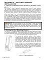
1
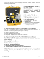
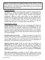
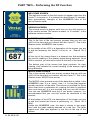
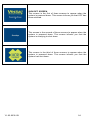
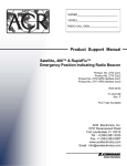
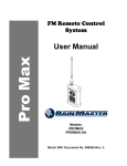
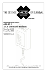
About Cobham Life Support, ACR Products
Cobham Life Support, ACR Products www.acrelectronics.com, designs and
manufactures a complete line of safety and survival products including
EPIRBs, PLBs, AIS, SARTs, Strobe Lights, Life Jacket Lights, Search Lights
and safety accessories. The quality systems of this facility have been
registered by UL to the ISO 9001:2000 Series Standards. Recognized as
the world leader in safety and survival technologies, ACR has provided
safety equipment to the aviation and marine industries as well as to the
military since 1956. The company is headquartered in Fort Lauderdale,
Florida and employs 200 at its manufacturing facility.
About Cobham plc
Cobham plc is an international company engaged in the development,
delivery and support of advanced aerospace and defence systems for land,
sea, air and space. The company has four division that collectively
specialize in the provision of components, subsystems and services that
keep people safe, improve communications and enhance the capability of
aerospace and defence platforms.
CAUTION: Before proceeding to install, test or use your new ACR
Electronics’ product, please read this Product Support Manual in its entirety.
If you have questions regarding the contents of the manual, please contact
our Technical Service Department at ACR Electronics, Inc., Telephone +1
(954) 981- 3333. Please be ready to provide the technician with the page
number you wish to discuss. If you have a question that is not covered in the
manual, please visit our website and access the Frequently Asked
Questions (FAQs) section for further information or call our Technical
Service Department. The website address is www.acrelectronics.com.
If in the future you lose this manual, you may access and print a
replacement on the ACR website.
Y1-03-0235-1B
2
TABLE OF CONTENTS
PRODUCT DESCRIPTION _____________________________________ 4
OPERATION _______________________________________________ 7
UNDERSTANDING THE LCD DISPLAY __________________________ 10
RANGE EXERCISES _________________________________________ 12
APPENDIX A – EMERGENCY SCENARIOS ________________________ 16
APPENDIX B – Vecta™3 DISPLAY REFERENCE GUIDE _______________ 18
APPENDIX C – OPTIONAL BRACKET INSTALLATION ________________ 27
APPENDIX D – TECHNICAL SPECIFICATIONS _____________________ 28
APPENDIX E – WARRANTY, USEFUL LIFE POLICY, NOTICES __________ 29
APPENDIX F – ACCESSORIES __________________________________ 31
PLEASE READ ALL WARNINGS, CAUTIONS
AND NOTES CAREFULLY
Y1-03-0235-1B
3
PRODUCT DESCRIPTION
1. Vecta™3 Direction Finder with LCD display
The Vecta™3 Direction Finder provides an LCD display for viewing radio
signal strength, and can detect an AM radio signal typically down to
0.5µV. The signal strength indicator is used to determine bearing by
pointing the Vecta™3 towards the highest power reading and
proceeding in that direction. This product is capable of monitoring and
finding beacons transmitting on 121.5 MHz (emergency beacon
frequency) which includes PLBs, EPIRBs and ELTs. In this document,
these products may be collectively referred to as beacons.
The Vecta™3 kit includes a training beacon that operates on a
TRAINING frequency of your Vecta™3. The system is easy to learn,
even for the novice user. With practice using the training beacon for
simulated searches, beginners will be direction finding like seasoned
professionals in no time. See the Operation section of this manual.
The Vecta™3 has an open and closable small beam, direction-finding
antenna that is connected to a very sensitive AM receiver. There are
optional external antennas that may be purchased for certain
applications such as setting up a Vecta™3 as part of a monitoring
station. Under ideal conditions, the Vecta™3, at two meters above water
line, will detect a beacon floating at sea level from a distance of up to
8nm. Land based distances may vary due to changes in topography that
can block and reflect signals.
There are three Vecta™3 models, each of which includes different
components:
Vecta™3 Complete Kit, P/N 2869, offers all components needed
Vecta™3 Optional Kit, P/N 2869.1, is purchased as a second
unit, thus it does not include all components
Vecta™3 CE-marked Kit, P/N 2869.2, contains key items
needed
Y1-03-0235-1B
4
Your new Vecta™3 LCD Display Direction Finder comes with the
following components.
Figure 1
2. Unpacking the Vecta™3
Kit, P/N 2869
A complete kit containing
everything that is needed to
perform a direction finding
operation:
1
3
2
6
4
5
1. Heavy duty Pelican® case
2. Vecta™3 Direction Finder
3. Water resistant carrying case
™
4. Mini B2 ILS training beacon
5. AC power adapter
(110-240V AC / 12V DC)
6. Headphone
7. Mounting bracket (not shown)
8. Training beacon floatation
collar (not shown)
3. Unpacking the Vecta™3, P/N 2869.1 (not shown)
This kit is packed for those needing additional Direction Finders.
includes the following items (see figure 1 above):
It
2. Vecta™3 Direction Finder
3. Water resistant carrying case
5. AC power adapter (110- 240V AC / 12V DC)
4. Unpacking the Vecta™3, P/N 2869.2 (not shown)
This kit has been CE- approved and includes the following items (see
figure 1 above):
1. Heavy duty Pelican® case
2. Vecta™3 Direction Finder
3. Water resistant carrying case
™
4. Mini B2 ILS training beacon
7. Mounting bracket (not shown above)
8. Training beacon floatation collar (not shown above)
NOTE: If desired, you may purchase headphones from your preferred
vendor. However, the CE Mark is valid only for the stand-alone
Vecta™3.
Y1-03-0235-1B
5
5. Direction Finder and test beacon features
1.
2.
3.
4.
5.
6.
7.
8.
9.
10.
11.
12.
Antenna elements
External antenna connector
LCD display
SELECT/ ENTER button
MENU button
UP button
DOWN button
ON/ OFF button
NUMBERS/ MICRO button
External headphone jack
External 12VDC power jack
Mini B™2 Test/Training beacon
2
1
3
4
5
6
7
8
9
10
11
12
Figure 2
Y1-03-0235-1B
6
OPERATION
1. Operation steps
TURN THE UNIT ON. The system will boot to a screen that has a
large area for numbers, and displays the operational frequency of
the receiver.
VERIFY THE OPERATIONAL FREQUENCY. Default is 121.5MHz.
If you will be searching for a training beacon, change the receiver
frequency of the Vecta™3 to that of the transmitting training beacon.
See “Operation tips” below for more detail.
FIND A BEARING. Hold the unit as shown in Figure 3. Slowly turn
your body and determine the bearing that has the highest signal
strength. See “Operation tips” below for more detail.
MOVE TOWARD THE HIGHEST SIGNAL STRENGTH. Be watchful
of signal strength as you go. See “Operation tips” below for more
detail.
WHEN THE SCALE REACHES 999 YOU ARE WITHIN A FEW
FEET OF THE BEACON
2. Operation tips
Holding the Vecta™3
Turn the unit on. If you intend to use the Vecta™3 for training, be sure
that you have switched to a TRAINING frequency and confirm that the
frequency you are using matches the frequency of the training beacon.
See information in this section
Figure 4
and Appendix for details on how
to change frequency.
Hold the Vecta™3 in the left
hand away from your body, in a
vertical orientation and at ear
level. Holding the Vecta™3 in
this manner also polarizes the
antenna
with
a
vertically
oriented beacon antenna and
improves the ability to hear
signals in the early stages of a
search by positioning the
Vecta™3 speaker next to your
ear.
Y1-03-0235-1B
Figure 3
7
NOTE: The left-hand front antenna element of the Vecta™3 is the
electrically active element and the body’s effect on the front to back ratio
of the antenna is minimized when in this position. The unit will work in
either hand but, if no signal is heard when searching, you may want to
try different polarization positions.
Using headphones
Headphones can assist in the early stage of a search when the signal is
very weak, i.e., when just entering the range of a transmitter. The
Vecta™3 does not have a squelch function to utilize the maximum
receiver sensitivity, thus there is always ambient electromagnetic
interference (EMI) or static noise heard on the speaker and
headphones. The EMI can overpower the signal of a distant transmitter.
At times the sweeping audio tone (whoop, whoop, whoop…) of a
beacon can be heard faintly amidst the static by listening with the
headphones. When this occurs the beacon is located in the general
direction that the Vecta™3 is pointed. Move in that direction.
Searching for a beacon
Slowly rotate 360°, taking about 2 minutes, listening for a 121.5 MHz (or
training frequency) beacon audio tone. The NUMBERS screen will
display fluctuations in readings, increasing and decreasing, as you
rotate nearer and farther away from the beacon’s signal. There are two
indication modes for deciding the direction of the beacon: You must take
your time when rotating and keep the Vecta™3 in the same position
relative to your body, as you turn to minimize the effects of your body on
your power readings.
Sweeping audio tone mode:
When just coming into range of the
beacon (weak signal) an audio sweeping tone will be your guide for
direction. A louder tone will be received from the beacon direction. If no
tone is heard, rotate the unit in your hand 90° and scan the horizon all
around (360°) listening for a tone. See below for an explanation of
polarization. If a tone is heard, the beacon is in range.
Numeral indicator mode: When the audio tone has stabilized, as
signal strength increases and the receiver locks on the signal, the
NUMBERS screen will increase the data (number), indicating an
increase in beacon signal strength, as you approach the beacon. Signal
strength can be observed in two different modes: NUMBERS and
BARS. See next section and Appendix for an explanation of NUMBERS
and BARS modes.
PLB signal emissions: In addition to the 121.5MHz warble sound
(wee-ooo, wee-ooo) emitted by beacons, PLBs in particular also send a
Morse Code P sound (de-beep-beep-beep-de) approximately every 50
seconds (in the United States). Both can be heard using the Vecta™ 3.
Y1-03-0235-1B
8
When determining bearing you can fine tune your bearing by using the
MICRO scale and looking for the highest power reading, slowly
scanning from left and right. You should see where the power starts to
drop off from the highest power reading and proceed forward in that
highest readings’ direction. Walking or not holding the Vecta™3 in its
operation position can be misleading when trying to read the display.
Ensure that you are always in the operating position when recording
power measurements.
Polarizing the beacon and the Vecta™3
The ability of the Vecta™3 to pick up a weak signal is improved when
the antenna of the Vecta™3 is oriented in the same polarization as the
antenna of the transmitter.
In a blind search, the polarization of the beacon’s antenna is unknown.
The beacon could be standing up or laying down. To polarize the
antennas, rotate the Vecta™3 antennas from a horizontal position to a
vertical position so they are in alignment with the transmitting beacon’s
antenna. The Vecta™3 is not polarized when the antenna blades of the
unit are in a perpendicular orientation with respect to the transmitting
antenna.
The Vecta™3 is polarized for maximum signal strength when the
antenna blades of the unit are in a parallel orientation with the transmit
antenna.
Figure 4
Polarized with Beacon
Figure 5
Not Polarized with Beacon
Once the tone is heard and the rescuer is heading in the direction of the
beacon, the NUMBER screen or MICRO screen can be expected to
increase the signal strength readout, showing that the beacon is nearer.
The audio tone will remain constant.
Using MICRO display
The MICRO display uses a bar graph to display beacon signal strength.
Before switching to this view, first determine from the NUMBERS view
Y1-03-0235-1B
9
which direction had the highest radio signal level. Then switch the
Vecta™3 from the NUMBERS display to the MICRO display, and place
the unit in a hand held searching position- in the direction of the highest
reading- immediately upon pushing the NUMBERS/MICRO key.
Scan the area a few degrees to the right and a few degrees to the left to
more accurately pinpoint the bearing that you want to proceed on. The
display will move up and down relative to beacon signal strength.
Proceed in the direction of highest signal.
Press the MICRO button again to return to NUMBERS display. See the
next Section and the Appendix for detailed information about the LCD
display.
Using a training beacon
To set the Vecta™3 to the frequency of the training beacon:
Read the frequency on the label of the training beacon
Using the Menu function, set the frequency of the unit to match the
beacon (see Appendix for details about using the display screen and
keypad)
Setting up the system on external power
To run the Vecta™3 on an external power source use the 12VDC power
jack located on the end of the Vecta™3. See Figure 2, number 11 for
location.
UNDERSTANDING THE LCD DISPLAY
1. NUMBERS, BARS and MICRO
The NUMBERS screen and the BARS screen provide the same data in
two different forms. You can use either one or both, whichever works
best for you. Most people prefer the NUMBERS screen, thus it is the
primary screen. The MICRO screen magnifies the current signal level to
determine bearing more accurately. It does not cover the entire range of
signals that can be detected, and should be used as a “close up view”
but not be depended upon as the entire view.
WHAT THE NUMBERS MEAN: The further from the beacon
transmitter, the smaller the number. The closer to the beacon
transmitter, the larger the number (maximum of 999).
2. User interface structure
The Vecta™3 has an LCD display that functions much like other
consumer electronic devices. Often used functions appear as buttons on
the unit. User preferences and setup are available via a menu, which is
accessed from a button, navigated via up/down buttons, and
preferences selected via a confirmation button. Below is a map of the
user interface structure (Figure 6). Also see the Appendix for more
details regarding the screens.
Y1-03-0235-1B
10
Figure 6
Y1-03-0235-1B
11
RANGE EXERCISES
1. Selecting a location for the test beacon
Range exercises involve placing the test beacon in an area similar to
where rescues are expected to take place, then moving away from the
beacon in measured distances and recording the signal strength. For
open water searches, anchor the beacon in an area where there is at
least 8 nautical miles of open water in all directions. Secure the beacon
so it cannot be moved or pulled under by wind or current. Attaching the
beacon to an orange life buoy or similar floatation device in addition to
the supplied floatation collar will improve the beacon’s visibility in heavy
seas.
If the application is an oil platform, anchor the test beacon in an area
around the platform. If at an airport, place the test beacon somewhere
on the airport grounds. If you expect to conduct a search in more than
one environment, do a range exercise in each environment. This will
help you build experience with the Vecta™3 and how the effects of your
particular search environment impact the radio waves traveling from a
beacon.
2. Recording observations
Once the test beacon is placed and the location accurately determined,
turn the test beacon on and point the Vecta™3 directly at the beacon.
Record the NUMBERS and MICRO reading. Move away from the test
beacon, recording NUMBERS and MICRO readings at intervals of 0.25,
0.75, 1.0, 1.5, 2.0, 2.5, 3.0, 3.5, 4.0, 5.0, 6.0, 7.0, 8.0 (nautical and/or
statutory miles) etc., until it can no longer be heard under any
circumstances. A form similar to the following may be helpful in
recording the results of your range exercise:
Radio signal level (example)
0.0
999
0.25
950
0.5
810
0.75
1.0 1.5 2.0 2.5 3.0 3.5 4.0 5.0 6.0 7.0 8.0
When doing a range exercise in the ocean, especially at greater
distances, wave height can cause a beacon to be heard intermittently as
it rides up out of a trough to the crest of a swell or wave and back down.
A GPS is invaluable in ensuring accurate distance intervals.
Emergency transmitters that emit the VHF 121.5 MHz frequencies are
limited to line of sight and will be detectable at a much greater range or
distance on the open ocean than on land. This is a function of the
transmitted signal being absorbed by hilly terrain, vegetation and
buildings.
Y1-03-0235-1B
12
3. Conducting a blind search
A partner hides the test beacon within a realistic search area. Place the
test beacon in an area that does not inhibit the signal, i.e., Avoid
situations such as in a hole, submerged under water, lying on its side,
laying on a metal plate, etc. A beacon can be found in these situations,
however these situations are considered advanced and should be
practiced only after the fundamentals are attained. The trainee using the
Vecta™3 need only be aware of the search area boundaries.
4. Search patterns
At the very beginning of a search, it is important to slowly rotate the
Vecta™3 antennas from horizontal to vertical and back when searching
for the signal. The signal will be more easily detected when the Vecta™ 3
becomes aligned or polarized with the antenna of the transmitter, which
may not be known to the searcher.
Once the signal strength rises above the EMI, the NUMBERS screen
should be used primarily to determine the directional bearing to the
transmitter.
Depending on whether a search is conducted on land or sea determines
the search pattern. On water, the pattern is methodical, beginning up
current working towards the opposite end of the search area. On land,
drive the perimeter of the search area, stopping periodically to sweep
the horizon with the Vecta™3.
AQUATIC SEARCH: Standard SAR Pattern - Move until a signal is
detected. Disconnect the Vecta™3 from the omni-directional antenna.
Sweep the horizon to establish a directional bearing to the beacon.
Once the direction is determined, continue towards the beacon. If the
signal becomes weak or disappears, return to the last known location
with a signal and take a new
bearing. This type of search
pattern is preferable for
aquatic based searches,
where
the
terrain
is
considered
flat
and
there
is
10nm
little concern for reflected
signals from objects. See
Figure 7.
10nm
Figure 7
Y1-03-0235-1B
13
Follow the strengthening signal. If it starts to fall or weaken, STOP!
Slowly move the Vecta™3 in a circle to clearly establish the strongest
signal direction.
LAND SEARCH: A cross-directional search pattern is useful when there
are a lot of false signals. Start the search heading in a straight line until
the signal weakens (Figure 8, A). Stop, and take a signal strength
reading at 90° from the current heading (Figure 8, B). Choose the
stronger signal (Figure 8, C). Continue in that direction until the beacon
is found (Figure 8, D), or the signal becomes weak. Repeat the process
crossing the straight path at 90° intervals when the signal starts to
weaken. Move in a straight line as the NUMBERS screen displays
strengthened readings. Do not deviate from the straight-line course as
long as the signal is strengthening.
Stop at the instant the
signal peaks and starts to
weaken. The beacon will
be laying close to a line
perpendicular to your
current course. Take
signal strength readings
at 90° angles from your
current
straight
line
course and heading and
try to determine if the
signal is stronger in one
direction or another. Turn
exactly 90° and repeat the first step of walking in a straight line as long
as the signal strengthens, stopping as soon as it begins to fall. If the
signal begins to weaken steadily from the moment you turn and start
moving, you are headed in the wrong direction. If signal is weakening,
turn around and work in the reverse direction.
Figure 8
When the signal strength peaks on the second leg of the search pattern,
the beacon will be closer. If visual contact isn’t made with the beacon, or
if there are still a lot of signal reflections, an additional 90° signal check
is performed. The new course is now parallel to the original course
heading.
5. Search Tips
Signal reflections, or false signals, can be a problem at any time during
the search. Signal reflections can be caused by large or metallic objects
such as buildings, bridges, airplanes, cars, trees, towers, ships, hills,
etc. or by being in a close or confined area, such as in a hangar. Signal
reflections can become more pronounced as you get closer to the
beacon.
Y1-03-0235-1B
14
A method to deal with signal reflections, if the signal strength is strong,
is to fold the antennas and hold the unit very close to the body. This will
reduce the sensitivity of the Vecta™3 and help alleviate extraneous
signal sources. For great sensitivity when searching, use the optional
Hand Held Direction Finding Antenna. See Appendix for accessories.
Use your body as a
shield by holding the
base of the Vecta™3
next to your abdomen.
This technique
will
cause the Vecta™3 to
receive
only
the
strongest
and
true
signal. This technique
is especially helpful in
confined areas such as
airplane hangars.
Y1-03-0235-1B
15
APPENDIX A – EMERGENCY SCENARIOS
1. Lost diver
Scenario: A yacht is cruising the Caribbean. A small group of SCUBA
divers have launched a dingy to a nearby shallow reef for a day of
diving. All the divers have been outfitted with a Mini B™ 300 personal
beacon. It is late afternoon, and after a beautiful day of diving, the winds
are starting to pick up. One of the divers has become lost and after an
unsuccessful search of the nearby area, the Dive Master radios the
yacht of the pending emergency.
The Dive Master returns the divers to the yacht as the captain monitors
the Vecta™3 from the helm station. The Captain hears the beacon alert
from the lost diver, removes the Vecta™3 from its bracket, and does a
quick “direction find” on the beacon signal. He then points the Dive
Master in the correct direction to recover the lost diver.
Action: The diver, realizing that the current is sweeping him further and
™
further away from the dingy, activates the Mini B300 ILS, inflates his
buoyancy compensator and waits for the boat.
On the yacht, unable to visually see the beacon, the Captain removes
the Vecta™3 from the bridge, moves to an open area of the boat,
extends the mini yagi antennas, and rotates the Vecta™ 3 360°, finding a
beacon signal. Using the standard SAR search pattern, the Captain and
Dive Master locate the missing diver a few miles down current.
2. ELT false activation
Scenario: A Cessna 172 makes a hard landing at the local airport,
setting off the impact activated ELT. An old fashioned TSO-C91 ELT
does not notify him that it is transmitting. He taxis to his tie down spot,
shuts down his plane and leaves, not realizing that his TSO-C91 ELT is
transmitting a signal to the Cospas-Sarsat satellite system.
Action: The airport manager, (or ATC, FBO, Unicom, etc.) is alerted to
the ELT transmission by the AC power connected Vecta™3. Airport
personnel respond by removing the Vecta™3 remote omni-directional
antenna connector and AC power supply, unfolding the directional
indicating antennas and initiating a search of the airport grounds to
identify the source of the emergency signal and to determine if indeed
there is an emergency, or if the signal has been set off by accident.
Within minutes they identify the Cessna, notify the owner that his ELT is
falsely transmitting, confirm the transmission via the onboard Nav-Com
radio and shut off the ELT.
Y1-03-0235-1B
16
3. Hiker rescued
Scenario: Three hikers set off for a weekend of climbing a local peak.
One hiker has a 406 GPS Personal Locator Beacon (PLB) in his
emergency kit. The hikers have properly registered it with NOAA, told
loved ones their itinerary, left a message on the dashboard of their SUV
and hiked to an altitude of 11,420 ft. While making camp, one hiker has
fallen down a deep ravine. The others become concerned when she
does not return and start a search. Night falls and there is no sign of
their companion. Out of cell phone range, they activate the PLB.
Action: Within minutes, the worldwide Cospas-Sarsat satellite system
picks up the GPS signal, forwarding the information to the Local User
Terminal. The Mission Control Center receives the information from the
Local User Terminal and passes the information to the local Rescue
Coordination Center. There, authorities receive the information and,
using the information from the PLB’s registration, verify that this is an
emergency. They then contact the local Search and Rescue authorities
and notify them that a beacon has been activated in their jurisdiction.
SAR maps the GPS coordinates and initiates a search. Even with the
GPS coordinates, SAR opt to use the (optional) hand held direction
finding antenna for better reception in the deeply wooded area. Getting
within range, they use the 121.5 MHz homing signal with the Vecta™ 3
for pinpoint accuracy. Using the cross directional search pattern, SAR
finds two persons and learns of the third, lost hiker. Additional resources
are called in, and within a few hours the hiker is found, with possibly life
threatening injuries. A helicopter evacuates the injured hiker and the
remaining hikers continue their journey to the summit the next day.
Y1-03-0235-1B
17
APPENDIX B – Vecta™3 DISPLAY REFERENCE
GUIDE
This section explains how the Vecta™3 user interface is organized, how
it functions and how you may interact with it. Please read this section in
its entirety.
PART ONE – Interacting with the Keypad
Y1-03-0235-1B
SELECT/ENTER
Press this key to actively
select your choices for
system setup
MENU
Press this key for the
primary menu screen, i.e.,
The screen that presents
all categories of user
options
UP
Press this key to toggle
upward on the LCD screen
to your selection
DOWN
Press this key to toggle
downward on the LCD
screen to your selection
ON/OFF
Press this key to turn the
Vecta™3 on and off. It has
no other function.
NUMBERS/
MICRO
Press this key to toggle
between the NUMBERS
view and the MICRO view
while performing an active
search
or
a
training
exercise
18
PART TWO – Performing the DF Function
WELCOME SCREEN
The welcome screen is the first screen to appear each time the
Vecta™3 is turned on. It is present for about three (3) seconds,
then automatically changes to the NUMBERS view of the
active Search mode.
VERSION SCREEN
The second screen to appear each time you turn the system on
is the version screen The version number, or “K number”, is the
software revision number.
NUMBERS VIEW SCREEN
This is the first of the two primary screens that you will use
>95% of the time that you interact with the Vecta™3. This is the
Search mode, NUMBERS view screen.
In the middle of the LCD is a description of the screen you are
in and the frequency the Vecta™3 is set to, i.e., “Search 121.5
MHz”.
At the top of the screen there is a dynamic bar that estimates
the current reading of the beacon signal being detected. Once
999 is reached, you should be within a few feet of the beacon.
The bottom part of the screen has large numbers, for easy
viewing, that indicate the current reading of the beacon signal
being detected.
MICRO VIEW SCREEN
This is the second of the two primary screens that you will use
>95% of the time that you interact with the Vecta™ 3. This is the
Search mode, MICRO view screen.
The MICRO view presents most of the data that is visible in the
NUMBERS view: It is a “zoom” view, i.e. A view that supplies
greater resolution of the data. This screen is provided for those
users that have a preference for viewing the data in graphical
form and close-up. It is not required that you use the screen.
You can use NUMBERS view only if you prefer, however, it is
recommended that you use this screen as described in this
manual.
At the bottom of the LCD is a description of the screen you are
in and the function the Vecta3 is performing, i.e., “Micro 121.5
MHz”.
Unlike the NUMBERS view, the data is shown in bar graph
form with the peak reading denoted as a red line. The radio
signal level data also appears in the box at the top of the
screen.
Y1-03-0235-1B
19
POWER DOWN
If the system is not interacted with for >59 minutes, the system
will automatically shut down to save battery charge. You will be
alerted visually as well as via beeps that the system is getting
ready to shut down. Press any key to abort the shut down
sequence and continue using the system.
PART THREE – User Preferences and Settings
MENU SCREEN
When you press the menu key on the keypad, you will see this
screen. From this screen, all user programmable settings can
be accessed and modified.
Press the up arrow key or down arrow key on the Vecta™ 3
keypad to select the function that you want to change.
To change volume, highlight VOLUME by using the up arrow
key or down arrow key.
Press the Select/Enter arrow key to indicate that you want to
change the volume. The VOLUME screen will appear (below).
NOTE: The volume may also be adjusted directly from the
keypad by using the up arrow key and the down arrow key
VOLUME SCREEN
When in the VOLUME screen, press the up arrow key or down
arrow key to adjust the volume up or down. The system will
mimic the volume level as you move up and down the scale.
Please note that you will hear beeps representing volume
changes but you will also hear static in the background at the
same time.
The filled-in green bars indicate the sound level setting. The
bars outlined in green indicate volume levels not enabled.
When you are satisfied with the setting change, press the
Select/Enter arrow key to indicate that you want the new setting
to be stored.
If you do not interact with the system 10 seconds, the system
will return to normal operational use. No changes are made.
Press the Menu key to go back one menu level.
Y1-03-0235-1B
20
To change the operational frequency of the Vecta™3, highlight
FREQUENCY using the up arrow key or down arrow key.
Press the Select/Enter arrow key to indicate that you want to
change the training frequency. The FREQUENCY screen will
appear (below).
FREQUENCY SCREEN
When in the FREQUENCY screen, press the up arrow key or
down arrow key to select your preferred operating frequency.
If you wish to select the actual search frequency, highlight
“121.5 MHz” in the red bar. Note that this frequency is for live
(real) searches only.
Press the Select/Enter arrow key to indicate the frequency that
you want to use.
When using non-emergency frequencies, the word “Train” will
appear on the operational screen to indicate to the user that
they are not on the emergency frequency search channel.
If you do not interact with the system 10 seconds, the system
will return to normal operational use. No changes are made.
Press the Menu key to go back one menu level.
NOTE: When the system is turned on, the frequency is
automatically set to 121.5MHz no matter what frequency was
used previously.
To change the LCD format or color, highlight DISPLAY using
the up arrow key or down arrow key.
Press the Select/Enter arrow key to indicate that you want to
change the display. The FORMAT/ COLOR screen will appear
(below).
DISPLAY OPTIONS SCREEN
To change to the preferred data format, highlight FORMAT
using the up arrow key or down arrow key.
Press the Select/Enter arrow key to indicate that you want to
change the format of the data. The BARS/ NUMBERS screen
will appear (below).
Y1-03-0235-1B
21
Highlight BARS, using the up arrow key or down arrow key, if
you wish to view the entire range of real time data in a vertical
bar graph format.
Press the Select/Enter arrow key. The BARS screen will appear
(below).
Once the BARS mode is selected, the system enters the search
mode using BARS as the view of the data. The BARS view,
when selected, replaces the NUMBERS view.
This view provides a more visual indication of the radio signal
when monitoring. As the signal level increases, the bars fill in
with color.
Highlight NUMBERS, using the up arrow key or down arrow
key, if you wish to view real time data as a large number with a
horizontal bar at the top.
Press the Select/Enter arrow key. The NUMBERS screen will
appear (below).
Once the NUMBERS mode is selected, the system enters the
search mode using NUMBERS to display the beacon signal
level.
Highlight COLOR to change the to the preferred color format,
using the up arrow key or down arrow key.
Press the Select/Enter arrow key to indicate that you want to
change the color scheme of the screens. The DEFAULT/ HIGH
CONTRAST screen will appear (below).
Highlight DEFAULT, using the up arrow key or down arrow key,
if you wish to view the screens in color, i.e, blue, green and
white.
Press the Select/Enter arrow key. The DEFAULT color scheme
will appear (below).
Y1-03-0235-1B
22
Once the DEFAULT view is selected, the system enters the
search mode using DEFAULT color scheme on all screens.
If you do not interact with the system 10 seconds, the system
will return to normal operational use. No changes are made.
Press the Menu key to go back one menu level.
Highlight HIGH CONTRAST, using the up arrow key or down
arrow key, if you wish to view the screens in black, grey and
white. Some users find this color scheme easiest to see in
bright outdoor conditions.
Press the Select/Enter arrow key. The HIGH CONTRAST color
scheme will appear (below).
Once the HIGH CONTRAST view is selected, the system
enters the search mode using HIGH CONTRAST color scheme
on all screens.
If you do not interact with the system 10 seconds, the system
will return to normal operational use. No changes are made.
Press the Menu key to go back one menu level.
BACKLIGHT SCREEN
To change the backlight status, highlight BACKLIGHT using the
up arrow key or down arrow key.
Press the Select/Enter arrow key to indicate that you want to
turn the backlight off or on. The next screen you see will reflect
the change (example below).
After you depress the Select/Enter arrow key from the
BACKLIGHT selection, the display will change to either on or
off.
If you do not interact with the system 10 seconds, the system
will return to normal operational use. No changes are made.
Press the Menu key to go back one menu level
DEFAULT SCREEN
To change all settings back to default, highlight DEFAULT
using the up arrow key or down arrow key.
If you do not interact with the system 10 seconds, the system
will return to normal operational use. No changes are made.
Press the Menu key to go back one menu level.
See PART FOUR below for default settings.
Y1-03-0235-1B
23
SIGN OFF SCREEN
This screen is the first of three screens to appear when the
system is powered down. This screen informs you that OFF has
been selected.
This screen is the second of three screens to appear when the
system is powered down. This screen informs you that the
system is readying to shut down.
This screen is the third of three screens to appear when the
system is powered down. This screen informs you that the
system has shut down.
Y1-03-0235-1B
24
PART FOUR – User Interface Behaviors
Default settings
Vecta™3 default settings include:
View: NUMBERS view
Volume: Mid-level
Receiver frequency: 121.5MHz
LCD color scheme: Blue, ACRtreuse™, white
Backlighting: Off
User programmable settings retained
Settings adjusted by the user that will be saved
when the system is powered down include:
Volume
LCD color scheme
Main search screen (either NUMBERS
or BARS)
User programmable settings not
retained
Settings adjusted by the user that will not be
saved when the system is powered down
include:
Training mode/training frequency
selection
Backlighting on
Length of time to view Peak Reading
A peak reading remains stationary for 30
seconds and then “fades away” over a period of
60 seconds in the BARS and MICRO screens. A
new peak reading then replaces the previous
peak reading.
Time- outs
The system will time out in 10 seconds in the
user programmable settings screens, if you do
not interact with the system.
The system will time out in 10 minutes when in
MICRO view mode. It will return to the
NUMBERS or BARS view and reset the MICRO
display. If the signal strength reading remains
out of range, the system will time out in 2
minutes.
The WELCOME SCREEN times out in 3
seconds.
Also see Battery save mode, below
Length of time a screen can be
viewed
A user programmable settings screen can be
viewed for 9+ seconds before a selection is
made.
User cancellation
You may cancel something you are doing by
pushing the Menu key or by waiting 10 seconds
for the system to time out. The system will go
back to the current mode.
Y1-03-0235-1B
25
If MICRO view reaches maximum
data display
If the MICRO mode reaches its maximum data
display and you want to continue to use MICRO
mode, reset the system by depressing the
NUMBERS/ MICRO key. You may do this an
indefinite number of times.
Battery save mode
The system is programmed with a battery save
mode, i.e., It will automatically power down
when the system has not been interacted with
for 60 consecutive minutes. You will be alerted
with sound and a visual message before the
system shuts down. If you reset the system by
pressing any button, it will not shut down.
System beeps
The system emits a beep every time the keypad
button is pressed, as a form of feedback.
Return to main search screen
Following changes made by you to the system,
the system returns to NUMBERS or BARS
screen, i.e., The mode you were in when you
initiated settings changes.
To enable On or Off
Hold the On/Off key down for 2 consecutive
seconds
Y1-03-0235-1B
26
APPENDIX C – OPTIONAL BRACKET
INSTALLATION
1. Remote Omni-Directional Antenna (Rooftop, Pole,
etc…)
The Vecta™3 has a specially designed and tuned 3’ whip antenna
(121.5 MHz) available as an optional accessory (See Accessory
section). The antenna should be mounted as high as is practical for
optimum receiver range. Route the coaxial cable to where the Vecta™3
is mounted and connect via the external antenna connector cable.
When the Vecta™3 is in its mounting bracket, the Omni-Directional
Antenna should be plugged in to achieve optimum performance while in
the “monitoring” mode. When a radio signal has been detected, remove
the Vecta™3 from its bracket, disconnect the Omni-Directional Antenna
and deploy the antenna blades for search mode. This antenna requires
a marine-style antenna mount with a 1” x 4 thread. These mounts can
be sourced in several styles at marine stores locally.
WARNING: Do not attempt to use the Vecta™3 with any other
antennas. The Search-and-Rescue frequencies are not standard, and
using the wrong antenna can seriously degrade performance of the
Vecta™3. Only use remote antennas approved by ACR Electronics. See
Accessories section.
2. Folding Handle / Mounting Bracket
The Vecta™3 is supplied with a folding handle that also functions as part
of the mounting bracket. This handle allows the Vecta™3 to be hand
held while searching and also to be secured to a fixed bracket when not
in use or monitoring for emergency signals.
Figure 10
To mount the bracket, select a flat location,
allowing for the antenna and power wires to be
routed. Before drilling holes and screwing down
the bracket, test fit the Vecta™3 making sure the
unit is able to slide in and out of the bracket
unobstructed. The clearance should be at least
8.5in/ 21.6cm. It is not necessary to deploy the
antenna blades while the unit is in its bracket and
attached to the remote Omni-Directional Antenna.
See back cover of this manual for installation
template for mounting bracket.
Figure 11 - Mounting bracket
Y1-03-0235-1B
27
APPENDIX D – TECHNICAL SPECIFICATIONS
Vecta™3 LCD Display Direction Finder
Frequency Received
Search Channel: 121.5 MHz
Training Channel: 121.375, 121.600, 121.650,
121.775 MHz
Frequency Stability
.005% (crystal controlled)
Operating Temperatures
-10°C to +55°C (14°F to + 131°F)
Operating Life:
16 hours continuous on one battery (no
backlight), unlimited operating life on either AC
or DC power supply
Activation
Manual “ON-OFF” switch
Size
9.0 x 2.5 x 1.5 in (23 x 6 x 4 cm)
9.0 x 16.0 x 1.5 in (23 x 40.6 x 4 cm) with
antenna opened
Weight
15.6 oz (442 g) with battery and handle
Color
Stainless steel with blue label
Limited Warranty
1 Year
Mini B™2 test beacon
Frequency
121.775MHz Test (Other frequencies can be
special ordered: See Accessories)
Power Output
Minimum 75 mW
Operating Life
48 hours minimum at –20°C, (-4°F) longer in
temperature climates
Battery
2 – 2/3 A Lithium (DL223A Duracell) common
camera battery, readily available
Emission
Type A3X
Modulation
Downward sweeping tone between 1600 and
300 Hz at 2 to 4 sweeps per second
Attachments
Lanyards, hanked
Y1-03-0235-1B
28
APPENDIX E – WARRANTY, USEFUL LIFE
POLICY, NOTICES
1. Limited Warranty
This product is warranted against factory defects in material and
workmanship for a period of 1 (one) year* from date of purchase or
receipt as a gift. During the warranty period ACR Electronics, Inc. will
repair or, at its option, replace the unit at no cost to you for labor,
materials and return transportation from ACR. For further assistance,
please contact our Technical Service Department at ACR Electronics,
Inc., 5757 Ravenswood Road, Fort Lauderdale, FL 33312-6645.
Phone: +1 (954) 981-3333, Fax: +1 (954) 983-5087, Email:
[email protected].
This warranty does not apply if the product has been damaged by
accident or misuse, or as a result of service or modification performed
by an unauthorized factory. Except as otherwise expressly stated in the
previous paragraph, THE COMPANY MAKES NO REPRESENTATION
OR WARRANTY OF ANY KIND, EXPRESS OR IMPLIED, AS TO
MERCHANTABILITY, FITNESS FOR A PARTICULAR PURPOSE, OR
ANY OTHER MATTER WITH RESPECT TO THIS PRODUCT. The
Company shall not be liable for consequential or special damages.
To
place
the
warranty
in
effect,
register
online
www.acrelectronics.com or return the attached card within 10 days.
at
*Five years for the following products: EPIRB, PLB, S-VDR, SSAS.
2. Useful Life Policy
The typical service life of a properly maintained product is limited to 12
years from date of manufacture. Products that are 12 years and 1 month
or older from date of manufacture will not be serviced by ACR or our
Battery Replacement Centers. A product that is 12 or less years old
from date of manufacture will be serviced as long as the unit appears fit
to be placed back into its final operational cycle. Service includes the
replacement of those items that must be replaced at service intervals
and the verification that the device appears to be in good mechanical
and electrical working condition by an ACR authorized service
technician.
Y1-03-0235-1B
29
3. Notices
FCC Compliance Statement
NOTE: This equipment has been tested and found to comply with the
limits for a Class B digital device, pursuant to part 15 of the FCC Rules.
These limits are designed to provide reasonable protection against
harmful interference in a residential installation. This equipment
generates, uses and can radiate radio frequency energy and, if not
installed and used in accordance with the instructions, may cause
harmful interference to radio communications. However, there is no
guarantee that interference will not occur in a particular installation. If
this equipment does cause harmful interference to radio or television
reception, which can be determined by turning the equipment off and
on, the user is encouraged to try to correct the interference by one or
more of the following measures:
Reorient or relocate the receiving antenna.
increase the separation between the equipment and receiver.
Connect the equipment into an outlet on a circuit different from that
to which the receiver is connected.
Consult the dealer or an experienced radio/TV technician for help.
ACR Electronics diligently works to provide a high quality Product
Support Manual, however, despite best efforts, information is subject to
change without notice, and omissions and inaccuracies are possible.
ACR cannot accept liability for manual contents. To ensure that you
have the most recent version of the Product Support Manual, please
visit the ACR website at www.acrelectronics.com.
©2009 by ACR Electronics, Inc., doing business as Cobham Life
Support. All rights reserved. Reproduction in whole or in part is
permitted only with permission of ACR Electronics, Inc. Ongoing product
improvements may change product specifications without notice.
Trademarks or registered trademarks are the property of their respective
owners.
Y1-03-0235-1B
30
APPENDIX F – ACCESSORIES
The following is a list of accessories and commonly replaced items.
Item
Description
Whip antenna
3ft, marine mount,
includes antenna
cable adapter (source
base mount locally)
3ft.coaxial cable,
includes antenna
adapter
Standard:
121.775MHz
Contact your ACR
representative
Hand Held Direction
Finding Antenna
Test Beacon
Test beacon, custom
(for 121.375, 121.600 or
121.650MHz
frequencies)
Battery for Test Beacon
Y1-03-0235-1B
Replacement lithium
battery
ACR Product
Number
2871
2870
2762.2
N/A
1092
31
EC DECLARATION OF CONFORMITY
ACR Electronics, Inc. hereby declares that the following product is in conformity with Directive 1999/5/EC
of the European Parliament and of the Council of 9 March 1999 on Radio Equipment and
Telecommunications Terminal Equipment (R&TTE). In accordance with the Directive, the product will be
marked with the CE conformity marking as follows:
Product:
Direction Finder
Model: Vecta 3 (ACR P/N 2869.2 only)
TM
Regulations and
Standards:
IEC 60945: 2002
ETSI EN 301 489-1 V1.6.1 (2005-09)
Manufacturer:
ACR Electronics, Inc.
5757 Ravenswood Road
Fort Lauderdale, FL 33312
USA
European
Representative:
ACR Electronics, Inc.
(European Office)
1 Rose Cottages, Pitmore Lane,
Sway, Lymington, Hampshire
SO41 6BX, United Kingdom
Signed on behalf of ACR Electronics Inc.
Signed: ______________________________________________
Name:
Kerry Greer
Title:
Executive Director Research & Development
Document Vecta3-003
Date: March 5, 2009
This Declaration complies with ISO/IEC 17050-1:2004
ACR Electronics, Inc. is registered by UL to ISO 9001:2000
Y1-03-0235-1B
32