1
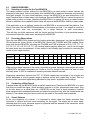
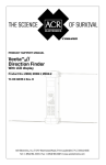
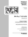
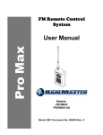
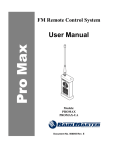
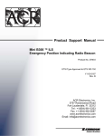
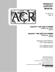
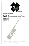
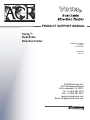
PRODUCT SUPPORT MANUAL
Vecta2™
Dual Scale
Direction Finder
Product No. 2769.4
121.5MHz
121.775 MHz
Y1-03-0227
Rev. A2
ACR Electronics, Inc.
5757 Ravenswood Road
Fort Lauderdale, FL 33312
Tel: +1(954) 981-3333
Fax: +1 (954) 983-5087
www.acrelectronics.com
Email: [email protected]
IF YOU HAVE ANY TROUBLE
WITH YOUR PRODUCT,
DO NOT RETURN IT TO THE STORE!
CALL ACR ELECTRONICS AT
+1 (954) 981-3333. WE WILL HELP YOU
RESOLVE ANY PROBLEMS YOU MAY BE
EXPERIENCING. MANY PROBLEMS CAN
BE CORRECTED OVER THE PHONE.
LIMITED WARRANTY
This product is warranted against factory defect in material and workmanship for a period of five years
from date of purchase or receipt as a gift. During the warranty period ACR Electronics, Inc. will , at its
option, repair or replace the unit at no cost to you for labor, materials or return transportation,
provided you obtain a Return Authorization from ACR Electronics, Inc., 5757 Ravenswood Road, Ft.
Lauderdale, FL 33312-6645.
To obtain a Return Authorization, call our Customer Service Department at (800) 432-0227. This
warranty does not apply if the product has been damaged by accident or misuse, or as a result of
service or modification by other than the factory. Except as otherwise expressly stated in the previous
paragraph, the COMPANY MAKES NO REPRESENTATION OR WARRANTY OF ANY KIND, EXPRESS
OR IMPLIED, AS TO MERCHANTABILITY, FITNESS FOR A PARTICULAR PURPOSE, OR ANY OTHER
MATTER WITH RESPECT TO THIS PRODUCT. The Company shall not be liable for consequential or
special damages.
You must complete the accompanying registration card and be return it to us within ten days of
purchase. Failure to do so may void the warranty.
1
Y1-03-0227 Rev. A2
Foreword
Thank you for purchasing from ACR Electronics, Inc. We design, manufacture and distribute
quality products knowing they are used to save lives. Many of our products are required to be
tested and approved by regulatory bodies worldwide. We believe in going beyond those
specifications to insure our products work when needed in real world conditions. With proper care
and maintenance your ACR product will last for years. It is important that you thoroughly read this
product support manual to understand the proper care and use of your ACR product.
ACR is proud to be certified to ISO 9001:2000, the International Standard for Quality.
This manual provides installation, operation and maintenance instructions for the Vecta2 Dual
Scale Direction Finder.
Table of Contents
1.0
PRODUCT DESCRIPTION....................................................................................................3
1.1
Introducing the Vecta2 Dual Scale Direction Finder............................................................3
1.2
Unpacking the Vecta2 P/N 2769.4 ......................................................................................3
1.3
Unpacking the Vecta2 P/N 2769.5......................................................................................3
1.4
Direction Finder and Test BEACON Features ....................................................................4
2.0
Installation ............................................................................................................................5
2.1
Remote Omni-Directional Antenna (Rooftop, Pole, etc…)..................................................5
2.2
Folding Handle / Mounting Bracket.....................................................................................5
3.0
Operation ..............................................................................................................................5
3.1
Holding the Vecta2 ..............................................................................................................5
3.2
Headphones .......................................................................................................................5
3.2
Headphones .......................................................................................................................6
3.3
Searching for a BEACON ...................................................................................................6
3.4
Polarization of the BEACON and the Vecta2 ......................................................................6
4.0
Understanding the Dual Scale ............................................................................................7
4.1
Reading Power Measurements to Determine Bearing and Direction..................................7
5.0
Range Exercises ..................................................................................................................8
5.1
Selecting a Location for the Test BEACON ........................................................................8
5.2
Recording Observations .....................................................................................................8
5.3
Conducting a Blind Search .................................................................................................8
5.4
Search Patterns..................................................................................................................8
6.0
EMERGENCY SCENARIOS................................................................................................10
6.1
Lost Diver .........................................................................................................................10
6.2
ELT False Activation.........................................................................................................11
6.3
Hiker Rescued ..................................................................................................................11
7.0
Technical Data....................................................................................................................12
7.1 Optional Accessories .............................................................................................................12
2
Y1-03-0227 Rev. A2
1.0
PRODUCT DESCRIPTION
1.1
Introducing the Vecta2 Dual Scale Direction Finder
The Vecta2™ Dual Scale Radio Direction Finder (DF) provides a Dual Scale signal strength meter
that can detect an AM radio signal typically down to .5µV. One scale is for COARSE power
readings and one scale for FINE power that is user friendly for use on land or at sea. These 2
scales work together to show the received signal strength and to determine bearing by pointing the
Vecta2 towards the highest power reading and then moving in that direction until the BEACON is
found. This product is capable of monitoring and finding BEACONs transmitting on 121.5 MHz
which includes PLBs, EPIRBs and ELTs. In this document, these products are collectively referred
to as BEACONs.
The Vecta2 Direction Finding Kit comes with a training BEACON that operates on the TRAIN
channel of your Vecta2. The Vecta2 is very intuitive for the novice user. Radio direction finding
practice using the Training BEACON for simulated real searches will have the most Novice user
Radio Direction Finding like a seasoned professional. With practice, the user will learn to overcome
reflected signals in heavily reflecting areas and determine the true signals direction.
The Vecta2 has an open and closable small beam, directional-finding antenna that is connected to
a very sensitive AM receiver that has been calibrated with a micro processor that interprets the
strength of a received signal. The dual LED scales are maximized when the Vecta2 is within a few
feet of the typical 75 mW emergency transmitter. Under ideal conditions the Vecta2, at two meters
above water line, will detect a BEACON floating at sea level from a distance of up to 8NM. Land
based distances may vary due to changes in topography that can block and reflect signals.
1.2
Unpacking the Vecta2 P/N 2769.4
Your new Vecta2 Dual Scale Direction Finder
comes with the following components:
1. Heavy Duty Pelican Case
2. External Antenna, 3ft
3. Vecta2 Dual Scale Direction Finder
4. Water Resistant Carrying Case
5. Mini B300™ ILS Training BEACON with Float
Collar
6. AC Power Adapter & 12V Power Adapter
7. Vecta2 Training CD
8. Headphone
Not shown: Mounting bracket
Training Beacon Flotation Collar
1
Figure 1
5
3
4
1.3
Unpacking the Vecta2 P/N 2769.5
Optional kit for those needing additional Direction
Finders:
7
3. Vecta2 Dual Scale Direction Finder
4. Water Resistant Carrying Case
6. AC Power Adapter
7. Vecta2 Training CD
6
2
8
3
Y1-03-0227 Rev. A2
1.4
Direction Finder and Test BEACON Features
1. Antenna Elements
2. External Antenna Jack
3 COARSE and FINE Signal Strength Meters
4. Search and Train Frequency indicator LEDs.
Search Freq – 121.5MHz
Train Freq – 121.775MHz
5. Search and Train frequency Receive Channel buttons
6. Volume Up and Down buttons
7. On and Off buttons
8. External Headphone Jack
9. External 12VDC Power jack
10. Mini B2 Training BEACON
2
1
3
4
5
10
6
7
8
9
Figure 2
4
Y1-03-0227 Rev. A2
2.0
INSTALLATION
2.1
Remote Omni-Directional Antenna (Rooftop, Pole, etc…)
The Vecta2 is supplied with a specially designed and tuned 3’ whip antenna (121.5 MHz) and
should be mounted as high as practical for optimum receiver range. Use a standard 1” x 14 thread
VHF style mount appropriate for your mounting location. Route the Coax to where the Vecta2 is
mounted and connect via the external antenna jack. When the Vecta2 is in its mounting bracket,
the Omni-Directional antenna should be plugged in to achieve optimum performance while in the
“Monitoring” mode. When a signal has been detected, remove the Vecta2 from its bracket,
disconnect the Omni-Directional Antenna and deploy the antenna blades for “Search” mode. While
the antenna looks and mounts like a standard 3' VHF marine antenna, it is not. Do not attempt to
use the Vecta2 with any other antenna. This action will damage the Vecta2 and may void the
warranty.
2.2
Folding Handle / Mounting Bracket
The Vecta2 is supplied with a folding handle that also functions as part of
the mounting bracket. This handle allows the Vecta2 to be hand held
while searching and also be secured to a fixed bracket when not in use
or is just monitoring. To mount the bracket, select a flat location allowing
for the antenna and power wires to be routed. Before drilling holes and
screwing down the bracket, test fit the Vecta2 making sure the unit is
able to slide in and out of the bracket unobstructed. It is not necessary
to deploy the antenna blades while the unit is in its bracket and attached
to the remote Omni-Directional antenna.
Figure 3
3.0
OPERATION
3.1
Holding the Vecta2
Turn the unit ON, (if used for training, switch to
Train mode) hold the Vecta2 in the left hand
away from your body, in a vertical orientation
and at ear level. Holding the Vecta2 in this
manner also polarizes the antenna with a
vertically oriented BEACON antenna and
improves the ability to hear signals in the early
stages of a search by positioning the Vecta2
speaker next to your ear.
Figure 4
The right-hand front antenna element of the Vecta2™ is the electrically active element and the
body’s effect on the front to back ratio of the antenna is minimized when in this position.
5
Y1-03-0227 Rev. A2
3.2
Headphones
Headphones can assist in the early stage of a search when the signal is very weak. When outside
the range of a transmitter, the Vecta2 will pick up ambient electromagnetic interference, (EMI), or
static noise. The EMI can overpower the signal of a distant transmitter. At times the oscillating tone
of a BEACON can be heard faintly amidst the static by listening with the headphones. When this
occurs the BEACON is located in the general direction that the Vecta2 is pointed. Move in that
direction.
3.3
Searching for a BEACON
Slowly rotate 360°, taking about 2 minutes, listening for a 121.5 MHz BEACON tone. The LEDs will
scroll up and down as you rotate nearer and farther away from the BEACON’s signal. The FINE
scale will climb when facing the BEACON. There are two indication modes for deciding the
direction of the BEACON: You must take your time when rotating and keep the Vecta2 in the same
position as you turn to minimize the effects of your body on your power readings.
Tone Mode: When just coming into range of the BEACON (Weak Signal) an audio tone will
be your guide for direction. A louder tone will be received from the BEACON direction. If no
tone is heard, rotate the unit in your hand 90° and scan the horizon all around (360°)
listening for a tone. See section 3.4 for an explanation of polarization. If a tone is heard, the
BEACON is in range, and the rescue can continue with greater pace.
Visual Mode: When Audio Tone has stabilized (as signal strength increases), the LED
Signal Meter will scroll in an upward fashion indicating an increase in signal strength, as you
approach the BEACON. Signal strength can be observed in two different modes: COARSE
and FINE. See section 4.0 for an explanation of COARSE and FINE signals.
3.4
Polarization of the BEACON and the Vecta2
The ability of the Vecta2 to pick up a weak signal is improved when the antenna of the Vecta2 is
polarized with the antenna of the transmitter.
In a blind search, the polarization of the BEACON’s antenna is unknown. To polarize the antennas
rotate the Vecta2 antennas from a horizontal position to a vertical position so they are in alignment
with the transmitting BEACON’s antenna. The Vecta2 is not polarized when the antenna blades of
the unit are in a perpendicular orientation with respect to the transmitting antenna.
The Vecta2 is polarized for maximum signal strength when the antenna blades of the unit are in a
parallel orientation with the transmit antenna.
Figure 5
Polarized with Beacon
Figure 6
Not Polarized with Beacon
6
Y1-03-0227 Rev. A2
Once the tone is heard and the rescuer is heading in the direction of the BEACON, the LEDs can
be expected to climb up the Signal Strength Meter visually showing that the BEACON is nearer.
The Audio tone will remain constant.
4.0 UNDERSTANDING THE DUAL SCALE
In most situations a searcher will focus on the COARSE scale to determine signal strength when
scanning the horizon (360°). In some situations a searcher will have two signals 180° opposite that
seem to be the same signal strength. Choosing the right direction oftentimes depends on very
small changes to the FINE scale. It is important to understand the relationship of the COARSE
scale to the FINE scale.
The further from the BEACON transmitter, the weaker the signal; the closer, the stronger the
signal. The Vecta2 Signal Strength Meters measure the decibel level of a signal in 256 units
displayed on two columns (16 x 16 = 256).
The COARSE and FINE scales are labeled 1-16. Each COARSE LED step represents a value
increase of 16 units which are represented in the FINE scale. As the Signal level increase the
scales climb up towards the top. When the FINE scale reaches 16 the COARSE scale will
increment up 1 unit.
4.1 Reading Power Measurements to Determine Bearing and Direction
The Vecta2 is designed to indicate the signal strength of a transmitting BEACON. With the
antennas deployed and held in its operating position the Vecta2 will be able to measure the signal
strength of the received signal and when pointing in the direction of the BEACON the Vecta2 will
display the highest power reading level (You need to determine this in your 360 degree sweep).
A COARSE scale reading of 2 combined with a FINE
scale reading of 10 equals an overall signal strength
value of 2.10.
Adding 7 FINE steps to the above signal strength forces
the next COARSE LED to illuminate and the FINE to
loop to 1 again, giving an overall signal strength value of
3.1.
Figure 7
Figure 8
When determining bearing you should be focused on the fine scale and looking for the highest
power reading and from slowly scanning left and right you should see where the power starts to
drop off from the highest power reading and proceed forward in that highest readings direction.
Walking or not holding the Vecta2 in its operation position can be misleading when trying to read
the power meter, ensure you are always in the operating position when recording power
measurements.
7
Y1-03-0227 Rev. A2
5.0
RANGE EXERCISES
5.1
Selecting a Location for the Test BEACON
This range exercise involves placing the test BEACON in an area similar to where rescues are
expected to take place, then moving away from the BEACON in measured distances and recording
the signal strength. For open water searches, anchor the BEACON in an area where there is at
least 8 nautical miles of open water in all directions. Secure the BEACON so it cannot be moved or
pulled under by wind or current. Attaching the BEACON to an orange life buoy or similar flotation
device in addition to the supplied flotation collar will improve the BEACON’s visibility in heavy seas.
If the application is an oil platform, anchor the test BEACON in an area around the platform. If an
airport, then place the test BEACON somewhere on the airport grounds. If you expect to conduct a
search in more than one environment, do a range exercise in each environment.
This will help you build experience with the Vecta2 and how the effects of your particular search
environment impact the radio waves traveling from a BEACON.
5.2
Recording Observations
Once the test BEACON is placed and the location accurately determined, turn the test BEACON
ON and point the Vecta2 directly at the BEACON. Record the COARSE and FINE reading. Move
away from the test BEACON, recording the COARSE and FINE at intervals of 0.25, 0.75, 1.0, 1.5,
2.0, 2.5, 3.0, 3.5, 4.0, 5.0, 6.0, 7.0, 8.0 (nautical and/or statutory miles) etc., until it can no longer
be heard under any circumstances. A form similar to the following may be helpful in recording the
results of your range exercise:
0.0
0.25
0.5
0.75
1.0
1.5
2.0
2.5
3.0
3.5
4.0
5.0
6.0
7.0
8.0
COARSE
FINE
When doing a range exercise in the ocean, especially at greater distances, wave height can cause
a BEACON to be heard intermittently as it rides up out of a trough to the crest of a swell or wave
and back down. A GPS is invaluable in ensuring accurate distance intervals.
Emergency transmitters that emit the VHF 121.5 MHz frequencies are limited to line of sight and
will be detectable at a much greater range or distance on the open ocean than on land. This is a
function of the transmitted signal being absorbed by hilly terrain, vegetation and buildings.
5.3
Conducting a Blind Search
A partner hides the test BEACON within a realistic search area. Place the test BEACON in an area
that does not inhibit the signal. (Avoid situations such as in a hole, submerged under water, lying
on its side, laying on a metal plate, etc. A BEACON can be found in these situations, however
these situations are considered advanced and should be practiced only after the fundamentals are
attained.) The trainee using the Vecta2 need only be aware of the search area boundaries.
5.4
Search Patterns
At the very beginning of a search, it is important to slowly rotate the Vecta2 antennas from
horizontal to vertical and back when searching for the signal. The signal will be more easily
detected when the Vecta2 becomes aligned or polarized with the antenna of the transmitter, which
may not be known to the searcher.
8
Y1-03-0227 Rev. A2
Watch the FINE signal scale for signs of a strengthening signal. Once the signal strength rises
above the EMI, the Signal Strength Meter should be used primarily to determine the directional
bearing to the transmitter.
Depending on whether a search is conducted on land or sea determines the search pattern. On
water, the pattern is methodical, beginning up current working towards the opposite end of the
search area. On land, drive the perimeter of the search area, stopping periodically to sweep the
horizon with the Vecta2.
Standard SAR Pattern - Move until a signal is detected.
Disconnect the Vecta2 from the omni-directional antenna.
Sweep the horizon to establish a directional bearing to the
BEACON. Once the direction is determined, continue
towards the BEACON. If the signal becomes weak or
disappears, return to the last known location with a signal
and take a new bearing. This type of search pattern is
preferable for aquatic based searches, where the terrain is
considered flat and there is little concern for reflected signals
from objects.
Figure 9
Follow the strengthening signal. If it starts to fall or weaken, STOP! Slowly move the Vecta2 in a
circle to clearly establish the strongest signal direction.
A cross-directional search pattern is useful when
there are a lot of false signals. Start the search
heading in a straight line until the signal weakens
(A). Stop, and take a signal strength reading at 90°
from the current heading (B). Choose the stronger
signal (C). Continue in that direction until the
BEACON is found (D), or the signal becomes
weak. Repeat the process crossing the straight
path at 90° intervals when the signal starts to
weaken. Move in a straight line as the Signal
Strength Meter strengthens. Do not deviate from
the straight-line course as long as the signal is
strengthening (see figure 10).
A
D
C
B
Figure 10
Stop at the instance the signal peaks and starts to
weaken. The BEACON will be laying close to a line perpendicular to your current course. Take
signal strength readings at 90° angles from your current straight line course and heading and try to
determine if the signal is stronger in one direction or another. Turn exactly 90° and repeat the first
step of walking in a straight line as long as the signal strengthens, stopping as soon as it begins to
fall. If for some reason you have chosen the wrong direction the signal will begin to weaken
steadily from the moment you turn and start moving. If signal meter shows the signal is weakening
turn around and work in the reverse direction.
9
Y1-03-0227 Rev. A2
When the signal strength peaks on the second leg of the search pattern, the BEACON will be
closer. If visual contact isn’t made with the BEACON, or if there are still a lot of signal reflections,
an additional 90° signal check is preformed. The new course is now parallel to the original course
heading.
Signal reflections, or false signals, can be a problem at any time of the search. Signal reflections
can be caused by large or metallic objects such as buildings, bridges, airplanes, cars, trees,
towers, ships, hills, etc. or by being in a close or confined area, such as in a hangar. Signal
reflections can become more pronounced as you get closer to the BEACON.
Signal reflections may cause numerous false directional indications. Fold the antennas and hold
the unit very close to the body. This will detune the Vecta2, and help alleviate extraneous noise.
For great sensitivity when searching, use the optional Hand Held Direction Finding Antenna, part
number 2870.
Use your body as a shield by holding the
base of the Vecta2 next to your abdomen.
This technique will cause the Vecta2 to
receive only the strongest and true signal.
This technique is especially helpful in
confined areas such as airplane hangars.
Figure 11
6.0
EMERGENCY SCENARIOS
6.1
Lost Diver
Scenario: A yacht is cruising the Caribbean. A small group of SCUBA divers have launched a
dingy to a nearby shallow reef for a day of diving. All the divers have been outfitted with a Mini B300
personal EPIRB. It is late afternoon, and after a beautiful day of diving, the winds are starting to
pick up. One of the divers has become lost and after an unsuccessful search of the nearby area,
the Dive Master radios the yacht of the pending emergency.
After bringing the remaining divers onboard the dingy, the Dive Master (DM) returns the divers to
the yacht as the captain monitors the Vecta2 from the helm station, noticing the FINE LED is
moving.
Action: The diver, realizing that the current is sweeping him further and further away from the
dingy, activates the Mini B300™ ILS, inflates his buoyancy compensator and waits for the boat.
On the yacht, unable to visually see the BEACON, the DM removes the Vecta2 from the bridge,
moves to an open area of the boat, extends the mini yagi antenna, and rotates the Vecta2 360°,
finding a signal. Using the standard SAR search pattern (figure 9), the captain and DM have
located the missing diver a few miles down current.
10
Y1-03-0227 Rev. A2
6.2
ELT False Activation
Scenario: A Cessna 172 inbound to land at the local airport bounces in on a hard landing setting
off the impact activated ELT. An old fashioned c91 ELT does not notify him that it is transmitting.
He taxis to his tie down spot, shuts down his plane and leaves, not realizing that his c91 ELT is
transmitting a signal to the COSPAS-SARSAT satellite system.
Action: The airport manager, (or ATC, FBO, Unicom, etc.) is alerted to the ELT transmission by the
AC power connected Vecta2. Airport personnel respond by removing the Vecta2 remote omnidirectional antenna connector and AC power supply, unfolding the directional indicating antennas
and initiating a search of the airport grounds to identify the source of the emergency signal and
determine if indeed there is an emergency or if the signal has been set off by accident.
Within minutes they identify the Cessna, notify the owner that his ELT is falsely transmitting,
confirm the transmission via the onboard Nav-Com radio and shut off the ELT.
6.3
Hiker Rescued
Scenario: Three hikers set off for a weekend of climbing a local peak. One hiker has a 406 GPS
PLB (Personal Locator BEACON) in their emergency kit. They have properly registered it with
NOAA, told loved ones their itinerary, left a message on the dashboard of their SUV and hiked to
an altitude of 11, 420 ft. While making camp, one hiker has fallen down a deep ravine. The others
become concerned when she does not return and start a search. Night falls and there is no sign of
their companion. Out of cell phone range they activate the PLB.
Action: Within minutes, the world wide COSPAS-SARSAT satellite system picks up the GPS
signal, forwarding the information to the Local User Terminal. The Mission Control Center receives
the information from the Local User Terminal and passes the information to the local Rescue
Coordination Center. There, authorities receive the information, and using the information from the
PLB’s registration, verify that this is an emergency. They then contact the local Search and Rescue
that a BEACON has been activated in their jurisdiction.
SAR maps the GPS coordinates and initiates a search. Even with the GPS coordinates, SAR opt
to use the (optional) hand held direction finding antenna for better reception in the deeply wooded
area. Getting within range, they use the 121.5 MHz homing signal with the Vecta2 for pinpoint
accuracy. Using the cross directional search pattern, SAR finds the duo and learns of the third, lost
hiker. Additional resources are called in, and within a few hours the hiker is found, with possibly life
threatening injuries. A helicopter evacuates the injured hiker and the remaining hikers continue
their journey to the summit the next day.
11
Y1-03-0227 Rev. A2
7.0
TECHNICAL DATA
Vecta2
Frequency Received
Frequency Stability
Operating Temperatures
Operating Life:
Activation
Size
Weight
Color
Limited Warranty
Search Channel - 121.5 MHz
Training Channel - 121.775 MHz
.005% (Crystal controlled)
-20°C to +55°C (-4°F to + 131°F)
16 hours continuous on one battery, unlimited operating life
on either AC or DC power supply
Manual “ON-OFF” switch
9.0 x 2.5 x 1.5 in (23 x 6 x 4 cm)
9.0 x 16.0 x 1.5 in (23 x 40.6 x 4 cm) with antenna opened
15.6 oz (442 g) with battery and handle
Stainless steel with blue label
1 Year
Mini B2 121.775 MHz test BEACON:
Frequency
Power Output
Operating Life
Battery
Emission
Modulation
Attachments
121.775 Test
Minimum 75 mW on each frequency
48 hours minimum at –20°, (-4°F) longer in temperature
climates
2 – 2/3 A Lithium (DL223A Duracell) common camera
battery, readily available
Type A3X
Downward sweeping tone between 1600 and 300 Hz at 2 to
4 sweeps per second
Lanyards, Hanked
7.1
Optional Accessories
P/N 2870 Hand Held Direction Finding Antenna. Improves reception of the 121.5 MHz signal.
12
Y1-03-0227 Rev. A2