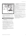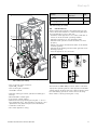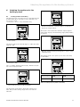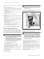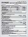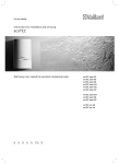
1
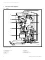
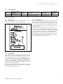
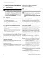
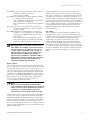
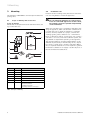
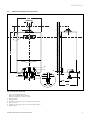
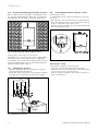
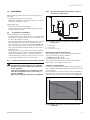
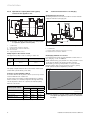
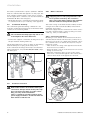
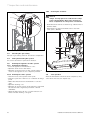
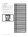
For the installer
Installation and maintenance manual
ecoMAX
Wall hung room sealed fan assisted condensing boiler
GB
ecoMAX 646
Contents
Notes on the documentation......................................
Other relevant documentation and service aids ...........
For the installer .....................................................................
Symbols used..........................................................................
1
1.1
1.2
1.3
1.4
1.5
3
3
3
3
Description of the appliance ........................... 4
Design .......................................................................... 4
Type summary ........................................................... 5
Data badge.................................................................. 5
CE marking.................................................................. 5
Intended use ............................................................... 5
5.2.1 Factory gas setting ...................................................
5.2.2 Checking the connection pressure
(gas flow pressure) ...................................................
5.2.3 Checking the CO2 content and adjusting it
if needed (air ratio setting) ....................................
5.3
Functional test ...........................................................
5.4
Instructing the user ..................................................
5.4.1 Instructing the user about the
heating system ..........................................................
5.4.2 Vaillant warranty.......................................................
20
20
21
22
22
22
6
2
2.1
2.1.1
2.1.2
2.1.3
2.1.4
Safety instructions and regulations ..............
Safety instructions ...................................................
Installing and setting the appliance .....................
Smell of gas.. ..............................................................
Changes to the surroundings of the boiler ........
Important instructions for propane
appliances ...................................................................
2.2
General requirements ..............................................
2.2.1 Preliminary remarks for roomsealed appliances
2.2.2 Related documents......................................................
6
6
6
6
6
3
3.1
3.2
3.3
3.4
8
8
8
9
3.5
3.6
4
4.1
4.2
Mounting ............................................................
Scope of delivery and accessories .......................
Installation site ..........................................................
Dimensional drawing and connections ................
Required minimum gaps/
assembly clearances ................................................
Mounting the appliance ...........................................
Removing/Attaching the appliance casing.........
4.8.4
4.8.5
Installation.........................................................
Preparing the installation .......................................
Technical instructions for the heating
system ..........................................................................
Direct feeding with heating pump located
in the interior of the device ...................................
Hydraulic decoupling with heating pump
located on the appliance side ................................
Technical instructions for recharging .................
Gas connection ..........................................................
Heating side connection ..........................................
Flue pipe ......................................................................
Condensate discharge .............................................
Electrical connection ................................................
Mains connection ......................................................
Connecting controllers ............................................
Connecting accessories and external
system components .................................................
Connection diagram .................................................
Wiring diagram ..........................................................
5
5.1
5.1.1
5.1.2
5.1.3
5.1.4
5.2
Start-up..............................................................
Water circulation system ........................................
Treating the heating water.....................................
Heating side filling and bleeding ...........................
Hot water side filling and bleeding .......................
Filling the siphon .......................................................
Checking the gas setting .........................................
4.2.1
4.2.2
4.3
4.4
4.5
4.6
4.7
4.8
4.8.1
4.8.2
4.8.3
2
6
6
6
6
10
10
10
11
11
11
Adapting the appliance to the heating
system................................................................
6.1
Setting partial-load heating....................................
6.2
Setting the pump run-out time..............................
6.3
Setting the pump output .........................................
6.3.1 Setting the pump output with direct feeding ....
6.3.2 Setting the pump output with hydraulic
decoupling...................................................................
6.4
Setting the burner lockout time ............................
19
7
7.1
7.2
7.2.1
7.2.2
23
23
24
24
24
24
24
25
25
25
26
7.2.3
7.2.4
7.2.5
7.3
7.4
7.5
7.5.1
7.5.2
7.5.3
7.6
Inspection and maintenance ...........................
Inspection and maintenance intervals.................
Inspection and maintenance instructions...........
Servicing the compact thermal module ..............
Cleaning the integral condensation heat
exchanger ...................................................................
Checking the burner .................................................
Cleaning the condensate siphon ...........................
Cleaning the condensate paths .............................
Checking the gas setting .........................................
Filling and bleeding the system .............................
Draining the appliance and the system ...............
Draining the appliance .............................................
Draining the entire system .....................................
Cleaning the air barrel .............................................
Test operation............................................................
8
8.1
8.1.1
8.1.2
8.1.3
8.1.4
8.1.5
Troubleshooting ................................................
Diagnostics .................................................................
Status codes ...............................................................
Diagnosis codes .........................................................
Error codes .................................................................
Error memory ............................................................
Test programs............................................................
29
29
29
30
31
31
32
9
Vaillant Service ................................................. 32
10
10.1
10.2
Recycling and disposal ..................................... 32
Appliance..................................................................... 32
Packaging .................................................................... 32
11
Technical data ................................................... 33
27
27
27
27
28
28
28
28
28
28
28
11
12
12
13
13
13
14
14
14
14
15
16
17
18
18
18
18
19
19
19
Benchmark gas boiler commissioning checklist...... 34
Installation and maintenance manual ecoMAX 646
Notes on the documentation
Notes on the documentation
The following information is intended to guide you
through the entire documentation.
Further documents apply in combination with this installation and maintenance manual.
We accept no liability for any damage caused by non-observance of these instructions.
Other relevant documentation
For the owner of the system
Brief operating instructions
Operating manual
Warranty cards
For the installer
Installation Manual
Flue accessories
Checklist
Sticker with name of appliance
Installation template
Safety sticker
and service aids
No. 00 20 00 64 61
No. 00 20 01 46 08
No. 80 29 22
No. 00 20 01 46 06
No. 00 20 02 01 60
No. 83 42 24
No. 12 41 82
No. 83 55 93
Service aids:
The following test and measuring equipment is required
for inspection and maintenance:
– CO2 measuring device
– U-pipe pressure gauge
Attachment and storage of the documents
Please pass on this installation and maintenance manual
as well as the aids to the owner of the system, whose responsibility it is to ensure that the manuals and auxiliary
equipment are available whenever required.
Symbols used
Please observe the safety instructions in this installation
manual when installing the appliance!
Danger!
Immediate risk of serious injury or death!
Caution!
Potentially dangerous situations for product
and environment!
Note!
Useful information and instructions.
•
Symbol for a necessary task
Installation and maintenance manual ecoMAX 646
3
1 Description of the appliance
1
1.1
Description of the appliance
Design
1
11
2
10
9
3
8
4
7
5
6
Fig. 1.1 Function elements
1
2
3
4
5
6
4
Connection for the flue pipe
Heat exchanger
Pressure switch
Pump
Electronics box
KFE cock
7
8
9
10
11
Air separator
Gas fitting
Ignition electrode
Compact thermal module
Air intake pipe
Installation and maintenance manual ecoMAX 646
Description of the appliance 1
1.2
Type summary
Appliance
type
ecoMAX 646
Country of destination
License
(designations
category
according to ISO 3166)
GB (Great Britain)
II2H3P
Type of gas
Nominal heat output
range P (kW)
Natural gas H - G 20 -20 mbar
(Propane - G 31 - 37 mbar)
13.3 - 47.7 (40/30 °C)
12.3 - 44.1 (80/60 °C)
Storage charging output
(kW)
44.1
Table 1.1 Type summary
1.3
Data badge
The data badge of the Valliant ecoMAX 646 is attached
at the factory to the bottom of the appliance.
1.5
Intended use
The Vaillant ecoMAX 646 is a state-of-the-art appliance
which has been constructed in accordance with recognised technical safety regulations. Nevertheless, danger
to the life and limb of the user or third parties can still
occur or the appliance or other material assets be damaged when using it.
The appliance is designed to be used as a heater for
closed hot water central heating systems. Any other use
or extended use is considered to be improper. The manufacturer or supplier is not liable for any damage resulting from improper use. The user alone bears the risk.
Appropriate use includes the observance of the operating and installation manual and the adherence to the inspection and maintenance conditions.
Fig. 1.2 Data badge (example)
1.4
CE marking
CE marking is used to document the fact that the appliances, in accordance with the type summary, meet the
basic requirements of the directive on appliances burning gaseous fuels (Council Directive 90/396/EEC) and
the EC directive on electromagnetic compatibility (Council Directive 89/336/EEC). The appliances meet the basic
requirements of the efficiency requirements directive
(Council Directive 92/42/EEC).
The appliances meet the basic requirements of the efficiency requirements directive (Council Directive 92/42/
EEC) as condensing appliances.
Installation and maintenance manual ecoMAX 646
5
2 Safety instructions
2
2.1
2.1.1
Safety instructions and regulations
Safety instructions
Installing and setting the appliance
Important!
The appliance must be installed and serviced by
a competent person as stated in the Gas Safety
(Installation and Use) Regulations 1998. In IE,
the installation must be in accordance with the
current edition of IS 813 ‚Domestic Gas Installations‘, the current Building Regulations and
reference should be made to the current ETCI
rules for electrical installation.
2.1.2 Smell of gas
If you smell gas, the following safety instructions should
be observed:
• don‘t switch on any electrical switch in the danger area,
• don‘t smoke in the danger area,
• don‘t use a telephone in the danger area,
• close the gas stop cock,
• air the danger area,
• notify a gas supplier or recognised gas fitting company.
2.1.3 Changes to the surroundings of the boiler
No changes must be made to the following devices:
– the boiler
– the gas, air, water and electricity supply pipes
– the exhaust pipe
– the discharge pipe and the safety valve for the hot
water
– the constructional conditions that could affect the
operational reliability of the device.
2.1.4 Important instructions for propane appliances
Bleeding the liquid gas tank when installing the system:
before installing the device, make sure that the gas tank
has been bled. The liquid gas supplier is responsible for
the proper bleeding of the tank. Ignition problems can
be caused if the tank is not bled properly. In such cases,
first contact the person in charge of filling the tank.
Affixing the tank sticker:
Affix the enclosed tank sticker (propane quality) on the
tank where it is clearly visible or on the bottle cabinet, if
possible close to the filler nozzle.
Installing underground:
When installing in underground places, the requirements
of the TRF 1996 (technical rules for liquid gas) are to be
observed. We recommend the use of an external solenoid valve.
6
Connection set for external solenoid valve:
Item no.: 306 253 or 306 248
Danger!
Only propane in accordance with DIN 51622
may be used.
Important!
When tightening or slackening screwed connections always use suitable open-ended spanners
(not pipe wrenches or extensions etc.).
Incorrect use and/or unsuitable tools can lead
to damage being caused (e.g. gas or water leakage)!
2.2
General requirements
2.2.1 Preliminary remarks for roomsealed appliances
This appliance should only be installed in conjunction
with either a Vaillant flue system or an alternative approved system (details of flue approval categories can be
found in the technical section of the installation manual).
Install the flue system as detailed in the separate flue installation instructions supplied with this boiler.
2.2.2 Related documents
The installation of the boiler must be in accordance with
the relevant requirements of Gas Safety (Installation
and Use) Regulations 1998, Health and Safety Document
No. 635 (The Electricity at Work Regulations 1989),
BS7671 (IEE Wiring Regulations) and the Water Supply
(Water Fitting) Regulations 1999, or The Water Bylaws
2000 (Scotland). It should also be in accordance with
the relevant requirements of the Local Authority, Building Regulations, The Building Regulations (Scotland).
The Building Regulations (Northern Ireland) and the
relevant recommendations of the following British
Standards:
BS 6700: Services supplying water for domestic use
within buildings and their curtilages.
BS 6798: Specification for installation of gas fired boilers not exceeding 60 kW input.
BS 6891: Specification for installation of low pressure
gas pipework up to 28 mm (R1) in domestic
premises (2nd family gas).
BS 7593: Treatment of water in domestic hot water central heating systems. Institute of Gas Engineers Publication IGE/UP/7/1998: ”Guide for
gas installations in timber framed housing”
BS. 5482 Pt. 1 Domestic butane and propane gas burning installations.
IGE/UP1 Soundness testing and purging of industrial
and commercial gas installation.
IGE/UP2 Gas installation pipework, boosters and compressors on industrial and commercial premises.
IGE/UP10 Installation of gas appliances in industrial and
commercial premises.
BS. 6644 Installation of gas fired hot water boilers of
rated inputs between 60 kW and 2 MW (2nd
and 3rd family gases).
Installation and maintenance manual ecoMAX 646
Safety instructions 2
BS. 5449 Forced circulation hot water central heating
systems for domestic premises.
Note: only up to 45 kW.
BS. 6880 Low temperature hot water heating systems
of output greater than 45 kW.
Part 1 Fundamental and design considerations.
Part 2 Selection of equipment.
Part 3 Installation, commissioning and maintenance.
BS. 4814 Specification for: Expansion vessels using
an internal diaphragm, for sealed hot water
heating systems.
BS. 5440 Installation and maintenance of flues and
ventilation for gas appliances of rated input
not exceeding 70 kW net (1st, 2nd and 3rd
family gases).
Part 1 Specification for installation of flues.
Part 2 Specification for installation and maintenance of ventilation for gas appliances.
Important!
When tightening or loosening screwed connections always use suitable open-ended spanners
(not pipe wrenches or extensions etc.). Incorrect use and/or unsuitable tools can lead to
damage being caused (e.g. gas or water leakage)! Preliminary remarks: This appliance
should only be installed in conjunction with a
Vaillant flue system. Install the flue system as
detailed in the separate flue installation instructions supplied with this boiler.
A compartment used to enclose the boiler must be
designed and constructed specifically for this purpose.
(An existing cupboard or compartment may be used provided that it is modified for the purpose). Details of essential features of cupboard/compartment design including airing cupboard installations are given in BS 6891. In
IE the current edition of IS 813. If the boiler is to be fitted in a timber framed building, it should be fitted in accordance with Institute of Gas Engineers Publication
IGE/UP/7/1998 “Guide for Gas Installation in Timber
Framed Housing”.
Gas Supply
The gas supplier should ensure the availability of an
adequate supply of gas. A gas meter may only be connected to the service pipe by the supplier of gas or their
contractor. An existing meter should be checked to
ensure that it is capable of passing the rate of gas
supply required. Installation pipes should be fitted in
accordance with BS 6891. Pipework from the meter to
the boiler must be of an adequate size. Do not use pipes
of a smaller size than the boiler gas connection (15 mm,
22 mm for 837/637). The complete installation must be
tested for soundness and purged as described in BS
6891.
Boiler location
The location chosen for the boiler must permit the provision of a satisfactory flue termination. The location must
also provide adequate space for servicing and air circulation around the boiler. The boiler may be installed in
any room, although particular attention is drawn to the
requirements of BS7671 (IEE Regulations), the electrical
provisions of the Building Regulations (Scotland) and in
IE the current edition of IS 813 and the current ETCI
rules, in respect of the installation of a boiler in
a room containing a bath or shower.
Note!
Where a room sealed boiler is installed in a
room containing a bath or shower, any electrical
switch or boiler control utilising mains electricity should be so situated that it cannot be
touched by a person using the bath or shower.
Where the installation of the boiler will be in an unusual
location, special procedures may be necessary and BS
5546 and BS 6798 give detailed guidance on this aspect.
The boiler must be mounted on a flat, vertical wall, which
must be sufficiently robust to take the weight of the
boiler. The boiler may be installed on a combustible wall,
subject to the requirements of the Local Authorities and
Building Regulations.
Installation and maintenance manual ecoMAX 646
7
3 Mounting
3
Mounting
The Vaillant ecoMAX 646 is delivered pre-mounted in a
package unit.
3.1
Scope of delivery and accessories
Scope of delivery
Check that all the parts have been delivered intact (see
fig. 3.1 and table 3.1).
1
2
8
7
6
3.2
Installation site
Please note the following safety instructions below before choosing where to install the appliance:
Caution!
Do not install the appliance in rooms prone to
frost. In rooms with aggressive steam or dust,
the appliance must be operated independently
of the ventilation!
When choosing the place of installation and while operating the appliance, make sure that the combustion air
is technically free of chemical substances containing
fluorine, chlorine, sulphur etc. Sprays, solvents and
cleaning agents, paints, adhesives etc. contain these
kinds of substances, which - in the worst case scenario can lead to corrosion, even in the exhaust system, during ambient air dependent operating of the appliance.
The appliance must be operated independently of the
ambient air particularly in hairdressing salons, carpenter‘s shops or paint shops, cleaning companies. Otherwise, a separate installation room is required to guarantee that the combustion air supply is technically free of
the above mentioned substances.
3
4
5
Fig. 3.1 Scope of delivery
Position
Quantity
Name
1
1
Bracket
2
1
Appliance
3
2
Connector - storage charging circuit
4
1
Condensate discharge hose
5
1
Bag containing consumables
6
1
Installation template
7
3
Manuals:
Operating manual
Installation manual
Assembly manual for flue pipe
Table 3.1 Scope of delivery
8
Installation and maintenance manual ecoMAX 646
Mounting 3
3.3
Dimensional drawing and connections
480
fl 80/125
190
94
A
1
800
2
4
3
7
Rp1
7
Rp1
6
5
70
100
144
100
fl 20
R1
100
180
R 3/4
450
Fig. 3.2 Connection dimensions
1
2
3
4
5
6
7
Flue connection Ø 80/125 mm
Dimension A with 87° elbow: 253 mm
Dimension A with 87° T-piece: 270 mm
Appliance holder
Heating return
Charging circuit return (only in conjunction with cylinder)
Gas connection
Charging circuit supply (only in conjunction with cylinder)
Heating supply
Installation and maintenance manual ecoMAX 646
9
3 Mounting
3.4
Required minimum gaps/assembly clearances
Both for the installation/assembly of the appliance and
for carrying out maintenance tasks later, you need the
minimum gaps and assembly clearances given below:
350
3.6
Removing/Attaching the appliance casing
Removing the casing
To dismount the front casing of the appliance, proceed
as follows:
• Unscrew the screw (1) on the bottom of the appliance.
• Press in both holding clips (2) on the bottom of the appliance so that the casing comes loose.
• Pull the casing (3) forwards by its bottom edge and lift
the casing up and off (4).
4
2
1
250
Fig. 3.3 Required minimum gaps/assembly clearances
3
Leaving gaps to the sides is not necessary.
Furthermore, it is not necessary to keep a gap between
the appliance and components made of combustible
constituents, since at the rated heating power of the appliance, the temperature here is never higher than the
permitted temperature of 85 °C.
3.5
Mounting the appliance
• Hang the appliance up into the appliance holder (1)
from above with the bracket (3).
• Mount the cable connections to the appliance, making
sure they are disconnected from the power supply.
Fig. 3.5 Removing/Attaching the appliance casing
Attaching the casing
To mount the casing, proceed as follows:
• Place the casing on the upper appliance holders.
• Push the casing onto the appliance so that the holding
clips (2) on the casing click into place.
• Fix the casing by screwing in the screw (1) on the bottom of the appliance.
240
75
50
75
50
2
85
23
1
3
Fig. 3.4 Mounting the appliance
10
Installation and maintenance manual ecoMAX 646
Installation 4
4
Installation
4.2.1
When installing, please observe the following points in
particular:
- Install the filling device in the return
- Guarantee minimum circulation by means of an overflow valve or hydraulic switch
Direct feeding with heating pump located in
the interior of the device
1
3
2
When recharging:
- Install the storage charging pump
- Install gravity brake in the heating supply and in the
storage charging circuit
3
230V~
4.1
Preparing the installation
Safety equipment for an emergency
• From the safety valve‘s blow-out line, a drain pipe with
intake guide and siphon must be led to a suitable outlet. The outlet must be visible!
• If plastic pipes are used in the heating system, a suitable maximum thermostat must be mounted on the
heating supply (e.g. Vaillant feed thermostat 009 642).
This is necessary in order to protect the heating system from temperature-related damage in the event of
a malfunction.
• When using plastic pipes that are not diffusion tight in
the heating system, a system separation between the
heater and system by means of an external heat exchanger must be performed in order to avoid corrosion
occurring in the heater circuit or in the boiler.
4.2
Technical instructions for the heating system
Caution!
The following system diagrams are schematic
diagrams. They do not replace the full professional diagrams!
The system diagrams do not contain the shutoff devices and safety devices necessary for
correct mounting.
Observe the applicable standards and guidelines.
3
53
Fig. 4.1 Example 1: radiator heating, direct feeding, applianceinternal pump
1 ecoMAX 646
2 heating pump
53 overflow valve (on site)
Pump layout; system dimensioning
The system planning is to be done such that in the design point optimally a water volume of:
V = 2000 l/h with T = 20 K
flows through the device and system.
The resulting residual delivery head for the system dimensioning is to be taken from fig. 4.2.
Setting the overflow valve
In order to guarantee the minimum circulating water volume of 1150 l/h through the appliance, install and set the
overflow valve.
We recommend you set the overflow valve to 250 mbar
with regard to possible noises at thermostat valves. The
overflow valve can, however, be set at up to 400 mbar.
Druck in mbar
900
850
800
Restförderhöhe ohne Schwerkraftbremse
750
700
Nennpunkt
650
600
550
500
450
400
350
300
Restförderhöhe mit Schwerkraftbremse
(Zubehör, Art.-Nr. 306 715)
250
200
150
100
50
0
0
200
400
600
800
1000
1200
1400
1600
1800
2000
2200
Volumenstrom in l/h
Fig. 4.2 Resulting characteristic curve (residual delivery head)
ecoMAX 646
Installation and maintenance manual ecoMAX 646
11
4 Installation
4.2.2 Hydraulic decoupling with heating pump
located on the appliance side
J
J
3
4.3
Technical instructions for recharging
Recharging kit (accessory)
Mounting instructions are to be taken from the manual
supplied with the recharging kit.
2
230V~
3
1
1
3
3
3
3
2
4
2
13
2
3
3
3
17a
3
230V~
45
3
3
Fig. 4.3 Example 2: radiator heating and floor heating, hydraulic separation, appliance-internal pump
1
2
13
13a
17a
ecoMAX 646
heating pump (appliance-internal)
weather-based controller VRC 420s
mixer module
supply temperature sensor
Fig. 4.4 Example 3: use of a cylinder, direct heating circuit
1 ecoMAX 646
2 heating pump (appliance-internal; accessory)
13 weather-based controller VRC 410
Pump layout in the heater circuit
The appliance pump is set according to table 4.1.
with gravity brake
without gravity brake
100 %
80 %
Pump
output
Table 4.1: pump output
The pump output must be set to the values in the table
(in the DIA system under point d.14).
Selection of the hydraulic switch
A suitable WH model hydraulic switch (accessory) can be
selected with the aid of table 4.2.
A sufficiently large water volume (minimum circulating
water volume) is constantly supplied through the boiler
via the hydraulic switch in conjunction with the pump
built into the boiler.
Recharging without accessories
It is imperative to keep to the minimum volume flow of
the charging circuit of 1800 l/h.
When dimensioning, pay attention to the pressure losses
of the gravity brake, the piping and the cylinder.
The heating circuit‘s gravity brake is to be put in the
heating supply; the storage charging circuit‘s gravity
brake can be mounted anywhere you like.
Druck in mbar
900
850
800
750
700
650
600
550
500
450
400
350
300
250
200
150
100
heating system spread
heating system output
10 K
15 K
20 K
ecoMAX 646
WH 95
WH 40
WH 40
double cascade
WH 160
WH 95
WH 95
triple cascade
WH 280
WH 160
WH 160
quadruple cascade
WH 280
WH 160
WH 160
50
0
0
200
400
600
800
1000
1200
1400
1600
1800
2000
2200
Volumenstrom in l/h
Fig. 4.5 The appliance‘s storage charging circuit without brake
and cylinder (the appliance‘s pressure loss characteristic curve)
Table 4.2: Selection of the hydraulic switch, WH model
12
Installation and maintenance manual ecoMAX 646
Installation 4
4.4
Gas connection
Caution!
Ensure the gas line is disconnected from the
power supply when mounting it so that no leaks
are caused.
Note!
When using a cylinder, a gravity brake is to be
mounted in the supply.
• Screw in supply (3) and return (4) with the maintenance cocks.
Caution!
The checking of the gas ducts for leaks may
only be carried out with a maximum pressure of
50 mbar, since otherwise the gas valve might
get damaged.
The appliance must be connected to your gas line via a
gas ball cock with a fire protection apparatus.
• Screw the appliance‘s gas supply pipe (1) gas-tight with
the (pre-installed) gas ball cock (2). To do this, use the
R3/4 compression fitting supplied with the appliance.
This is suitable for the connection of a R3/4 gas ball
cock.
• Inspect the gas connection for leakage.
3
4
Fig. 4.7 Mounting the heating supply and return
4.6
1
Flue pipe
Danger!
Only use original Vaillant flue pipes, since these
are authorized together with the boiler. Malfunctions can occur if you use other accessories. These may result in damage and injury.
2
Fig. 4.6 Gas connection (only surface installation possible)
4.5
Heating side connection
Caution!
Ensure the connecting cables are disconnected
from the power supply when mounting them so
that no leaks are caused in the heating system.
*
X
The appliance is connected to the heating supply and return via maintenance cocks. An installation set for the
ecoMAX 646 is available (item no. 306 715).
Caution!
It is imperative that the filling device be mounted in the return; otherwise, the bleeding of the
appliance is not guaranteed.
Fig. 4.8 Mounting example - vertical roof duct
* In case of x > 1 m an inspection hole has to be provided
Installation and maintenance manual ecoMAX 646
13
4 Installation
Concentric systems made of plastic (diameter - 80/125
mm) are combined with the appliance as flue pipes. The
most suitable system depends on the specific installation and application conditions (see also the installation
manual 83 44 49 for the flue pipes).
• Mount the flue pipes consulting the installation manual contained in the scope of delivery of this appliance.
4.8.1
4.7
Condensate discharge
The condensate generated during combustion is led
from the condensate discharge pipe to the waste water
connection via a draining funnel.
The rated voltage of the mains must be 230 V; at rated
voltages above 253 V and under 190 V, functional impairments are possible.
The mains supply must be connected via a fixed connection and a separator with a contact opening of at least
3 mm (e.g. fuses, circuit breakers).
Caution!
The condensate discharge pipe may not be connected tight to the waste water line.
• Connect the supplied condensate discharge hose (1) to
the pre-installed draining funnel (2).
The draining funnel also serves to drain off any heating
water that may be escaping at the safety valve.
If the condensate discharge line needs to be extended
during installation, only use DIN 1986/EN 12056 compliant drain pipes.
1
Mains connection
Caution!
Supplying power to false plug terminals of the
Pro E system can destroy the electronics.
Only connect the mains supply to the terminals
that are marked as being for that purpose.
4.8.2 Connecting controllers
Mounting is to be carried out as instructed in the relevant installation manual. The necessary connections to
the boiler‘s electronics (e.g. when using external controllers, external sensors or similar devices) are to be performed as follows:
• Take off the front casing of the appliance and lift the
electronics box (1) forward.
• Unclip the back cover (2) of the electronic box from its
fixings (3) and lift it up.
• Guide the connecting cables of each of the components to be connected through the cable routes (4) located on the bottom of the appliance to the left.
4
2
2
1
Fig. 4.9 Condensate discharge
4.8
Electrical connection
Danger!
Risk of fatal electric shock from touching live
connections. Always switch off the power supply to the boiler first. Only once this is done
may you carry out the installation.
There is continuous operating voltage at the
power supply terminals L and N even when the
main switch is switched off.
3
Fig. 4.10 Opening the rear of the switch box
14
Installation and maintenance manual ecoMAX 646
Installation 4
3
7 8 9
L N
3 4 5
RT 24V
230V
RT 230V
4.8.3 Connecting accessories and external system
components
The Vaillant ProE system facilitates a quick and troublefree conn