1
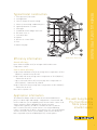
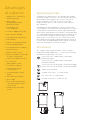
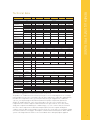
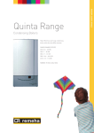
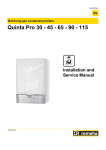
Quinta Pro Range
Condensing Boilers
HIGH EFFICIENCY
110% NCV AT 40/30°C
FULLY MODULATING
BOILER CONTROL
PREMIX BURNER CLEAN
COMBUSTION
ULTRA LOW NOx
BREEAM EXCELLENT
High efficiency wall hung condensing boiler
with ultra low NOx emission
QUINTA PRO RANGE OUTPUTS
QP30: 8.0 - 31.4 kW
QP45: 8.0 - 43.0 kW
QP65: 12.0 - 65.0 kW
QP90: 14.1 - 89.5 kW
QP115: 16.6 - 114.0 kW
SEDBUK ‘A’ (QP30, QP45, QP65)
100%
RECYCLABLE
REMEHA QUINTA PRO RANGE
The New Remeha
Introduction
Remeha Quinta Pro Range
are compact high-efficiency
wall hung condensing gas
boilers. Lighter and more
efficient, their small
dimensions make them
ideally suited for modular
arrangements.
An optional optimising/
weather compensating
control system is available to
ensure maximum efficiency.
The boilers can be installed
on both new and retrofit
installations.
High efficiency heating
(Production of domestic hot
water can be ensured by a
separate hot water calorifier).
Low pollutant emissions.
Very suitable for cascade
systems with several boilers.
Contents
page
Introduction
2
Boiler description
2
Typical boiler construction
3
Efficiency Information
3
Advantages at a glance
4
Operating principle
4
Dimensions
4
Technical data
5
Typical Installation
6
Typical flue systems
The Remeha Quinta Pro Range are wall hung, condensing
boilers which may also be installed free standing on a
suitable frame (option). The one piece, cast aluminium heat
exchanger and other major components are contained within
a sealed air box. This forms the main boiler casing with a
removable front section for maintenance purposes.
Electrical and electronic controls are contained within the
instrument panel mounted in the drop-down lower front
panel and also the electrical housing mounted on the inside
right hand panel.
The combined flue gas outlet and combustion air inlet are
mounted on the top of the boiler, with the flow, return, gas
and condensate connections located at the bottom.
The boiler is suitable for room-sealed or open flue
applications. It has been designed for central heating and
indirect hot water production. It must be installed on a fully
pumped system and is suitable for use on sealed systems
(0.8 bar) and open vented installations (For use on open
vented systems please contact our technical department).
The boiler's modulating control system limits the maximum
difference in temperature between the heating flow and
return and the maximum speed at which the flow
temperature increases. For this reason the boiler is, so to
speak, insensitive to a flow which is too low. In all cases,
maintain a minimum water flow of 0.4 m3/h.
The pre-mix, down-firing gas burner (NG or LPG) with its
gas/air ratio control system, ensures clean, trouble free
operation with higher than average efficiencies (of 110%
(NCV)) in the condensing mode, combined with ultra low NOx
and minimum CO emissions. The standard control package
allows actual and set values to be read and adjusted on the
built-in digital display which also provides normal operating
and fault code indication. An intelligent, advanced boiler
control continuously monitors the boiler conditions, varying
the heat output to suit the system load. The control is able to
react to external “negative” influences in the rest of the
system (flow rates and air/gas supply problems) maintaining
boiler output for as long as possible without resorting to a
lock out condition. At worst the boiler will reduce its output
and/or shut down (shut-off mode), awaiting the “negative”
conditions to return to normal before re-starting.
The control cannot override the standard flame
safety controls.
The boiler meets the requirements of the EC regulations
and directives:
-
90/396EEC
Gas appliances directive
-
92/42/EEC
Efficiency directive
-
73/23/EEC
Electrical low voltage directive
-
89/336/EEC
E.M.C. directive
CE Certification
7-8
Electrical installations and controls 9-11
2
Boiler description
Remeha Quinta 30/45/65/90/115 - PIN: 0063CL3333
1.
2.
3.
4.
5.
6.
7.
8.
9.
10.
11.
12.
13.
Flue gas outlet / Air intake
Casing/air box
Heat exchanger (Central heating)
Outlet for measuring combustion gases
Ignition/ionization electrode
Mixer pipe
Combined venturi and gas valve unit
Áir intake silencer
Instrument box
Siphon
Box for the control PCBs
Fan
Water flow pipe
Efficiency information
Quinta Pro illustrated
REMEHA QUINTA PRO RANGE
Typical boiler construction
Annual efficiency
Up to 109% at Hi (98% at Hs) at an input of 30% and a return
temperature of 30°C.
Heat to water efficiency
a. Up to 99% at Hi (89% at Hs) at an average water temperature of 70°C
(80/60ºC) - Quinta Pro 30, 45 & 65.
b. Up to 98% at Hi at an average water temperature of 70°C (80/60ºC)
- Quinta Pro 90 & 115.
c. Up to 110% at Hi (99% at Hs) at an average water temperature of
35°C (40/30ºC) - Quinta Pro 30, 45 & 65.
d. Up to 106% at Hi at an average water temperature of 35°C (40/30ºC)
- Quinta Pro 90 & 115.
Note: NCV = Hi, GCV = Hs
Application information
The Quinta Pro Range can be used on all new and refurbishment
projects in both single and multiple configurations. Conventional and
room-sealed flue system capability means that the boiler can be sited
almost anywhere within a building. The Remeha weather
compensators (options) are able to communicate directly with the
boiler controls (two wire) to make full use of its fully modulating
feature, ensuring that the boiler closely matches the system demand at
all times. External control systems (BMS) can be interfaced with the
boiler to provide on/off or modulating (0-10v) control options.
The wall hung Quinta
Pro from Remeha.
More power in a
smaller space.
3
Advantages
at a glance
• High efficiency: 110% NCV at
40/30ºC (99% GCV)
• Boiler control:
a) Modulating (18-100%)
b) On/off (18-100%)
• Premix burner for
clean combustion
• Low NOx < 25ppm (02=0%, dry)
• Quiet operation <52 dBA
• LED illuminated casing air box
• Digital display
• Data file for storing information
Operating principle
Combustion air is drawn into the closed air box, by a variable
speed fan, through the air inlet connection from the plant room
(open flued) or from outside via the concentric flue system
(room-sealed). On the inlet side of the fan is a specially
designed venturi which is connected to the outlet side of the
gas combi block.
Depending on the demand (under the dictates of flow/return
sensor and other external/internal control inputs) the electronic
control unit directly monitors the volume of gas and air being
delivered to the premix burner. This mixture is initially ignited by
the combined ignition/ionisation probe which then monitors the
state of the flame. Should the flame not ignite or be unstable,
within the pre-set safety time cycle, the controls will shut the
boiler down (after 5 attempts) requiring manual intervention to
reset the boiler. The digital display will also indicate a flashing
fault code confirming the reason for the failure.
• Remote signalling options
• Cast aluminium heat exchanger
• Easy maintenance
• Built-in calorifier control
• Options for modular control and/
or weather compensator
• Control 0-10V signal or volt free
• PC connection
• Advanced boiler control,
for reliable heat delivery
• Conventional or “roomsealed” operation
• Cascade packages for up to
6 boilers
• Quick and easy installation
• Space saving
• For use with natural gas and
L.P.G. (Some models require a
conversion kit)
• Suitable for pressurised flue
systems
4
Dimensions
The complete range of Quinta Pro boilers have a compact
design (h750 x w500 x d500) with 1 1/4" connections for heating
flow and return and 3/4" gas connection.
Connection of the combustion gas exhaust pipe ;
Ø 80mm (≤ 45 kW)
Connection of the combustion gas exhaust pipe ;
Ø 100mm (≥ 65 kW)
Connection of the air intake pipe ; Ø 125 mm (≤ 45 kW)
Connection of the air intake pipe ; Ø 150 mm (≥ 65 kW)
Siphon connection bush
Heating circuit return ; 1 1/4" Male thread
Gas connection ; 3/4" Male thread
Heating circuit flow ; 1 1/4" Male thread
BOILER TYPE
QUINTA PRO
30
45
65
90
115
16.6-107
GENERAL
EC identification no.
Flow rate setting
PIN
0063CL3333
Adjustable
Modulating, Start/Stop, 0 - 10 V
Nominal output (Pn) Heating
System (80/60°C)
Minimum maximum
kW
8.0-29.3
8.0-40.0
12.0-61.0
14.1-84.2
Factory setting
kW
29.3
40.0
61.0
84.2
107.00
Nominal output (Pn) Heating
System (50/30 °C)
Minimum maximum
kW
8.9-31.4
8.9-43.0
13.3-65.0
15.8-89.5
18.4-114
Factory setting
kW
31.4
43.0
65.0
89.5
114
Nominal input (Qn) Heating
System (Hi)
Minimum maximum
kW
8.2-30.0
8.2-41.2
12.2-62.0
14.6-86.0
17.2-110.2
Factory setting
kW
30.0
41.2
62.0
86.0
110.2
Nominal input (Qn) Heating
System (Hs)
Minimum maximum
kW
9.1-33.3
9.1-45.7
13.6-68.8
16.2-95.5
19.1-122.4
Factory setting
kW
33.3
45.7
68.8
95.5
122.4
Heating efficiency under full
load (Hi) (80/60 °C)
-
%
97.5
97.2
98.3
97.9
96.6
Heating efficiency under full
load (Hi) (50/30 °C)
-
%
102.9
102.9
104.6
104.1
102.5
Heating efficiency under
partial load (Hi) (Return
temperature 60°C)
-
%
97.5
97.5
98.3
96.6
96.5
Heating efficiency under partial
load (EN 92/42) (Return
temperature 30°C)
-
%
107.7
107.7
108.9
108.1
107.1
DATA ON THE GASES AND COMBUSTION GASES
Device categories
-
-
II2H3P
Gas inlet pressure G20 (Gas H) Minimum maximum
mbar
17- 30
Gas inlet pressure G31 (Propane) Minimum maximum
mbar
37 - 50
Gas consumption G20 (Gas H)
Minimum maximum
m3/h
0.9-3.3
0.9-4.4
1.3-6.6
1.5-9.1
1.8-11.7
Gas consumption G31 (Propane) Minimum maximum
m3/h
0.3-1.3
0.3-1.7
0.5-2.5
0.6-3.5
0.6-4.7
NOx-Emission per year
or (EN 483)
-
mg/kWh
<35
<37
<32
<39
<39
Mass flue gas flow rate
Minimum maximum
kg/h
14-50
14-69
21-104
28-138
36-178
Flue gas temperature
Minimum maximum
°C
30-65
30-67
30-68
30-67
30-72
-
Pa
70
150
100
160
220
5.5
5.5
6.5
7.5
7.5
0.3
0.5
140
250
Maximum counter pressure
REMEHA QUINTA PRO RANGE
Technical data
CHARACTERISTICS OF THE HEATING CIRCUIT
Water content
-
l
Water operating pressure
Minimum
bar
Water operating pressure
(Open vented)*
Minimum
bar
Water operating pressure
(PMS)
Maximum
bar
4.0
Water temperature
Maximum
°C
110
Water temperature
(Open vented)*
Maximum
°C
95
Operating temperature
Maximum
°C
90
Operating temperature
(Open vented)*
Maximum
°C
-
mbar
Water resistance (▲ = 20K)#
0.8
0.3
0.3
0.3
80
70
90
130
ELECTRICAL CHARACTERISTICS
Power supply voltage
-
VAC/Hz
Power consumption-Full load
Maximum
W
39
68
88
125
199
Power consumption
-Part load
Maximum
W
18
18
23
20
45
Power consumption-Standby
Maximum
W
5
5
6
4
7
-
IP
Electrical protection index
230/50
X4D
OTHER CHARACTERISTICS
Weight (empty)
Acoustic level at 1 meter
Total
kg
53
53
60
68
69
Mounting(1)
kg
50
50
57
66
67
-
dB(A)
38
45
45
52
51
(1) Front panel removed
*Available on request, contact Remeha technical department.
# Water resistance at 11 ▲ = Mbar QP30 - 231, QP45 - 300, QP 65 - 430, QP90 - 460, QP115 - 826.
The products of combustion in the form of hot flue gases are forced through the heat exchanger,
transferring their heat to the system water (the flue gas temperature is reduced to approximately
5°C above the temperature of the system return water) then discharged via the condensate
collector, vertically through the 80/125 mm (Quinta Pro 30/45) or 100/150 mm (Quinta Pro
65/90/115) combined flue/air connection to atmosphere. Because of the low flue gas exit
temperature there will be a vapour cloud formed at the flue gas terminal – this is not smoke,
simply water vapour formed during the combustion process. If the controls allow the flow and
therefore return temperature to fall below dew point (55°C) this water vapour will begin to
condense out in the boiler transferring it’s latent heat into the system water, increasing the output
of the boiler without increasing gas consumption. Condensation formed within the boiler and flue
system is discharged from the boiler to an external drain via the drain pan/siphon supplied.
5
Typical installation
Showing Quinta Pro 45/65/90/115. Simple schematics below do not constitute system
designs, please contact our technical department if you require any assistance.
Single boiler
Single boiler with low loss header
With DHW-Remeha priority
- Quinta Pro 30/45/65
Multiboiler
6
For Quinta Pro 90/115 use
a DHW primary pump
(open tube not supplied by Remeha)
Low loss header
A (dia.mm)
Connecting pipework A
- Boiler side
Based on 80°c/60°c Flow
Boiler side 20°∆T/System Side 11°∆T
No. of Boilers
Low Loss Header Dia mm
Connecting Pipework “A” mm
Connecting Pipework “B” mm
Dimension "A" mm
Dimension "B" mm
B (dia.mm)
Connecting pipework B
- System side
Quinta Pro 30/45
Quinta Pro 65/90
2
3
4
5
6
2
3
100 125 150 150 200 150 200
42 42 50 50 50 50 65
50 50 65 80 80 65 80
300 375 450 450 600 450 600
350 425 500 500 650 500 650
4
225
80
100
675
725
5
250
80
125
750
800
Quinta Pro 115
6
2
3
250 150 200
100 50 65
125 80 100
750 450 600
800 500 650
4
250
80
125
750
800
5
250
100
125
750
800
6
300
100
125
900
950
REMEHA QUINTA PRO RANGE
Multiboiler with low
loss header
Table above gives details for site fabricated low loss headers. Remeha can supply single, two, three and four boiler
headers and up to six boilers when suppled with a cascade or skid. Please see our additional sales brochures.
Typical flue systems
Concentric room-sealed applications
Quinta Pro 65/90/115
100/150 System
VRS roof mounted
room-sealed
terminal
Quinta Pro 30/45
80/125 System
Calculation data – room-sealed applications
Quinta Pro 30 Quinta Pro 45 Quinta Pro 65 Quinta Pro 90 Quinta Pro 115
80/125mm
80/125mm
100/150mm 100/150mm 100/150mm
Max eq. Length
m
eq. Length bend 45° m
eq. Length bend 90° m
20
1
2
16
1
2
13
1
2
13
1
2
7
1
2
7
Conventional flue
Bird guard and reduction cone
Calculation data – conventional flue
max eq. length
m
eq. length bend 45° m
eq. length bend 90° m
Quinta Pro 30
80mm
Quinta Pro 45
80mm
Quinta Pro 65
100mm
40
1.2
4
33
1.2
4
27
1.4
4.9
CLV system
(twin pipe - two zone)
Quinta Pro 90 Quinta Pro 115
100mm
100mm
24
1.4
4.9
19
1.4
4.9
Bird guard and reduction cone
Bird guard
PLEASE NOTE: For calculation data in regards to CLV installations (different pressure zones)
please contact our technical department - T: 0118 978 3434.
8
General
External connections
The Remeha Quinta Pro Range is supplied as
standard with electronic control and flame
ionisation safety controls, with a specially
designed microprocessor at the heart of the
control system.
All external connections are made to any
one of the standard supplied PCB's
depending on the type of control and
external components fitted.
Specifications
PCB (PCU-01)
Main PCB control
Connecting a third party control unit
Electrical supply
The Remeha Quinta Pro Range must have a
permanent 230V-50Hz single phase supply
rated at 6.3 amps. The control unit is not
phase /neutral sensitive.
Control box
Manufacture:
Model:
Supply voltage:
Electrical rating:
Pump run on (HTG):
SIT
PCU S01
230 V/50 Hz
10 VA
1 - 98 minutes
PCB (IF-01)
0-10v control
REMEHA QUINTA PRO RANGE
Electrical installation and controls
Fuse specification
The boiler is protected by fuses:
- F1 rated at 6.3 amps (slow acting).
- F2 230 volt, 2 amps (fast acting).
- Fan 230v.
Boiler temperature control
The Remeha Quinta Pro Range has electronic
temperature control with flow and return
temperature sensors. The flow temperature
can be adjusted between 20 and 90°C.
High limit temperature protection
The high limit, temperature protection device
switches off and locks out the boiler when the
flow temperature exceeds the high limit set
point (set by boiler type). When the fault is
corrected the boiler can be restarted by using
the reset key on the control panel.
Low water protection (flow and content)
PCB (SCU-X01)
This has two volt free
contacts, which can be
set as required.
Depending on the
setting, a maximum of
two messages about
the status of the boiler
can be transmitted.
PCB (SCU-S02)
For control of external central heating pump
(Pump) and control of external three-way valve
(3wV). Other features available.
The Remeha Quinta Pro Range are supplied
with a low water protection on the basis of a
low water pressure switch and also by
temperature measurement. By modulating
back at the moment that the water flow
threatens to fall too low, the boiler is kept
operating for as long as possible.
9
Boiler control
The Remeha Quinta Pro Range can be controlled using a number of methods - examples of
some are given below, please contact our technical or sales departments for further options.
Modulating (two wire control)
When using the optional Remeha compensating controllers the heat output modulates
between the minimum and maximum value on the basis of the boiler flow temperature
sensor. This applies to both single and multiple boiler installations, under the dictates of
a room and/or outside temperature sensor.
iSense - The iSense is a high quality thermostat /controller with revolutionary intuitive
controls. The iSense combines ease of use with an extensive range of options.
Remeha MC4 - In conjunction with the iSense controller can provide step control for multi
boiler installation of up to four boilers.
Analogue control (0-10 volt d.c.)
The heat output modulates between the minimum and the maximum values on the
basis of the voltage supplied by an external analogue (0-10V) input.
Analogue temperature-based control
The 0-10 V signal controls the boiler flow temperature between 0°C and 100°C. This
control modulates on the basis of flow temperature, whereby the heat output varies
between the minimum and maximum values on the basis of the flow temperature set
point calculated by the controller.
A jumper (2) on the interface is used to select either temperature control or heat output
control (%).
Analogue heat output-based control (%)
The 0-10V signal controls the boiler output between 0% and 100%.
The minimum and maximum values are limited. The minimum output is linked to the
boiler's modulation depth. The output varies between the minimum and maximum value
on the basis of the value determined by the controller.
Jumper 2
Jumper 2
Input signal (V)
Temperature
À À
Description
0-1.5
0-15
Boiler off
1.5-1.8
15-18
Hysteresis
1.8-10
18-100
Temp required
Input signal (V)
Heat output (%)
Description
0-2.0
%
(1)
0-20
Boiler off
2.0-2.2 (1)
20-22
Hysteresis
2.0-10 (1)
20-100
Heat output requested
(1) Dependent on the minimum modulation depth (set speeds, standard 20%)
10
Temperature control
With a Remeha temperature sensor or with a standard (volt free) DHW thermostat.
Note: will only provide a setting plus read out facility with the sensor option.
Primary flow control:
- With a three-way diverting valve. (Not Q90/115)
- With a DHW pump.
- Untimed (available 24 hours a day).
System/shunt pump
A shunt pump can be connected to the boiler (maximum input 200w). If the pump requires
more than this, terminals can only be used to switch a pump relay. The pump should be
fitted on the heating return connection and be as close to the boiler as possible. A system
pump can also be connected to the boiler via PCB SCU-S02 (maximum 400VA).
System water
Before operation the system should be cleaned and flushed (according to BS 7593 (2006)),
and filled with mains cold water. Suitable chemicals and their use should be discussed with
specialist water treatment companies in respect to aluminium heat exchangers. For further
information a special document "Remeha Water Quality Regulations" is available from
Remeha, the regulations in the document must be followed - www.remeha.co.uk
REMEHA QUINTA PRO RANGE
Priority DHW control
Frost protection
Install the boiler in a frost-free room. The built-in frost protection system is activated as
follows: Below 7°C - system pump is switched on if connected to boiler. Below 3°C - boiler
is switched on, when the flow temp reaches 10°C the boiler and pump switch off.
Note: This control is designed to protect the boiler - for full system protection use a frost
thermostat or a weather compensator.
Remote alarm and boiler run indication
As standard the boiler is supplied with 2 x volt free indicators - Common alarm signal and
boiler run signal. Maximum 230 volts, 1amp capacity each via PCB SCUX01.
Safety interlocks
As standard the boiler is supplied with shutdown (BL) and release (RL) inputs via the main
PCB control.
11
Remeha House
Molly Millars Lane
Wokingham
Berkshire RG41 2QP
T: 0118 978 3434
F: 0118 978 6977
E: [email protected]
www.remeha.co.uk
The data published in this technical sales leaflet is based on the latest information (at date of publication)
and may be subject to revisions. It should be read in conjunction with our full technical brochure (available
on request). We reserve the right to continuous development in both design and manufacture, therefore
any changes to the technology employed may not be retrospective, nor may we be obliged to adjust
earlier supplies accordingly. Issue 2 date: 01/11/2010
Remeha is committed to carbon offsetting
Designed and produced by Sans Frontiere Marketing Communications – 01273 487 800 – www.sansfrontiere.co.uk
Broag Ltd. Head Office