1
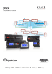
refrigeration
BY DAVE DEMMA
THE GOODS ON OIL FAILURE TRIPS
Do you remember that service call you were dispatched to where the frozen food was melting
in the display cases? Upon arrival you found the compressor off; apparently for quite some
time as its body was stone cold. A quick check of the control circuit with a voltmeter revealed
that the oil failure switch was the culprit.
After relieving the liquid refrigerant
from the crankcase you checked the oil
level. It was a little on the low side at 1/4
of a glass, but within the manufacturer’s
recommended limits. You carefully
restarted the compressor and proceeded
to check the net oil pressure. It was
measured to be 26 psi; again well within
the manufacturer’s specification.
Being a thorough technician, you
went the extra mile and verified the correct operation of the oil failure control.
You found the control’s switch opened
45 seconds after the net oil pressure had
fallen below 6.5 psi; perfectly within the
specification for the make/model of the
compressor. No visible cause was identified. This is a nuisance oil failure trip.
How inconvenient.
Let’s be clear though. The only nuisance regarding this scenario is that a
reason for the oil failure trip cannot be
easily determined. To imply that an oil
failure trip happens intermittently for no
reason implies that oil failure controls
have a mind of their own, and periodically decide to shut off a compressor
simply to add spice to the technician’s
life. Nothing could be further from the
truth. Unless an oil failure control is
defective, the only time it will trip is
when the compressor’s net oil pressure
falls below the control’s cut-in point for
the specified amount of time necessary
for the control to lockout.
REAL OIL PRESSURE
Understanding component operation
always makes troubleshooting system
problems easier; but first a brief explanation of the term “net oil pressure” is
required. The oil pump inlet is fed
86
HPAC •
80 years
MARCH 2006
through a screen located in the compressor sump, so crankcase pressure would be
the same as oil pump inlet pressure. The
pump takes this oil at crankcase pressure
and increases its pressure to some value
above crankcase pressure. Unless the
crankcase pressure is 0 psi, the oil pump
outlet pressure does not tell the complete
story. The real oil pressure, or “net oil
pressure,” is the difference between
pump inlet pressure (crankcase pressure)
and pump outlet pressure (discharge
pressure).
A brief review of how oil failure controls operate is in order. Unlike the typical low, high, or dual pressure control,
which has a single switch
FIGURE 1
in it, the oil failure control
requires two separate circuits to cause a lockout
after experiencing low net
oil pressure for a predetermined time (see
Figure 1).
The control circuit
switch
SC1 is a time delay switch
which is wired in series (at
terminals L and M) with
the other required controls
in the holding coil circuit
for the compressor motor
starter. It is considered the
slave in this arrangement,
and only opens when acted
upon by the time delay heater circuit. In
most applications SC1 would be a manual reset switch. However; if a start-stop station were used, an oil failure control with
an automatic reset switch could be used.
With this configuration an oil failure
control trip would cause the start-stop
station to open, locking out the compressor starter’s holding coil circuit. While
this provides foolproof lockout from low
oil pressure, oil failures with this control
arrangement are more difficult to troubleshoot. An automatic reset oil failure
control that trips the start-stop station
when low oil pressure occurs does not
leave any evidence that low oil pressure
was the problem for compressor lock-out.
The time delay heater circuit
This circuit requires a 208/240 volt supply to be applied between terminals V1
and 2 (or 120V between terminals V and
2). P1 is a normally closed differential
pressure switch which is connected to the
compressor crankcase and the oil pump
discharge. It measures net oil pressure.
P1 opens when the net oil pressure is
above the cut-in point for the control,
however the cut-in point will vary
OIL FAILURE CONTROL
depending on the compressor manufacturer’s specification. Some controls allow
for adjustment to the cut-in point, and
others are preset. H is a resistance heater;
the device which trips switch SC1 when
CONTINUED ON PAGE 90
BACHARACH
Refrigerant Vacuum Pumps
4-Port Refrigerant Manifolds
• Two stage rotary vane pump
• 1/4” and 3/8” flare and 1/2" ACME
intake ports
• Light, compact and well balanced
• High performance vacuum, HP and
CFM ratings for all AC/R applications
• One year warranty
• 15 micron factory rating
• H.D. aluminum block
• 3/8” vacuum port fitting
• 1/4” flare hose fittings
• Protected gauges
• H.D. hanging hook
• Colour coded easy grip handles for positive
control
•
SHOW & TELL
PRESENTED BY
NEW PRODUCTS FROM BACHARACH
R-410A Manifold (2002-4350)
R-22, R-12, R-134A Manifold (2002-4375)
QV2 Vacuum Pump 1.7 CFM
(2002-0001)
QV5 Vacuum Pump 5.5 CFM
(2002-0005)
www.bacharach-inc.com
Circle #46
MARCH 2006
80 years • HPAC
87
PRESENTED BY
H O N E Y W E L L G E N E T RO N
SHOW & TELL
•
HONEYWELL GENETRON‚ REFRIGERANTS:
THE BEST OPTIONS FOR R-22 REPLACEMENT
As R-22 becomes less available due to allocation
reductions by Environment Canada as part of the
global phaseout of hydrochlorofluorocarbon (HCFC)
refrigerants, contractors and equipment owners need
suitable replacements. Two hydrofluorocarbon (HFC)
refrigerants serve as substitutes for R-22: Genetron®
407C and Genetron® AZ-20® R-410A. While both have
proven to have excellent performance, each has distinct
characteristics that have led to different uses.
R-407C is designed to mimic
R-22, and allows for easy
conversion of existing R-22
systems to a non-ozone
depleting refrigerant. R-407C
replaces R-22 in existing air
conditioning and mediumtemperature
commercial
refrigeration systems, including supermarket display
cases and reach-in coolers.
Converting to R-407C allows manufacturers to use
existing production lines, compressors and other R-22
components. In the United States in 2002, several commercial bakeries retrofitted their R-22 refrigeration systems as part of an agreement with the U.S.
Environmental Protection Agency, with R-407C seeing
the most use in medium-temperature applications without flooded evaporators.
In contrast, R-410A represents an advancement in
refrigerant technology with several thermophysical properties that improve on R-22 performance. Because of
higher design pressures, it is only used in new residential and commercial air conditioning equipment. Various
HVAC manufacturers have taken advantage of the superior properties of R-410A, making new systems that are
smaller, quieter, and even more reliable than their R-22
versions. While R-410A requires redesigned equipment
and tooling due to its higher pressures, it allows for
smaller, more economic designs because of pressuredrop and other characteristics. Its near-zero glide also
allows for easier recovery and reclamation.
while awareness of R-410A as the solution for new
residential air conditioners remained flat. To help dealers educate consumers and builders on the transition
to R-410A, Honeywell launched www.410A.com, a
website that helps educate customers on the R-22
phaseout and their refrigerant choices, and also
launched an R-410A advertising and awareness campaign for homebuilders.
Globally, R-410A and R-407C
have contrasting positions in air
conditioning. In North America,
R-410A has become the refrigerant of choice for R-22 replacement, and today, most OEMs
offer a line of R-410A equipment.
R-407C, however, holds a strong
position in Europe and Japan
where environmental regulations
forced the industry to move
quickly away from HCFC-22.
Because the shift from R-22 was so rapid, compressors and other parts for R-410A were not yet available,
forcing the industry to move to R-407C for new air conditioners and retrofitting existing systems.
Today, many HVAC manufacturers in Europe and
Japan are shifting from R-407C to R-410A because of
compact equipment designs and better availability of
parts designed for R-410A. But R-407C still finds a
range of uses on both sides of the globe, including
several types of new equipment made in North
America, such as packaged rooftop chillers. R-407C is
also found in several types of imported equipment,
including mini-split air conditioners, bus and transit air
conditioning systems, and specialty chillers used for
metal processing and other applications.
Honeywell offers a full line of R-22 replacements,
including Honeywell Genetron® 407C and Genetron®
R-410A in a wide variety of package sizes. For more
information on refrigerants and refrigeration topics,
visit www.genetron.com.
Awareness is Key
Despite these successes, awareness of R-410A and R407C and the R-22 phaseout still varies. According to an
October 2004 survey of 500 residential homebuilders in
North America, awareness of the R-22 phaseout had
increased up 10 percent compared to December 2003,
Genetron® Refrigerants
Exclusive distributor of Genetron refrigerants in Canada
Ontario and Western Canada Tel: (416) 243-9615 Fax: (416) 243-9731
Quebec and the Maritime Provinces Tel: (514) 457-3628 Fax: (514) 457-9773
St. Lawrence Chemical Inc.
Exclusive distributor of Genetron refrigerants in Canada
Ontario and Western Canada, Tel: 416-243-9615 Fax: 416-243-9731
Quebec and the Maritime Provinces, Tel: 514-457-3628 Fax: 514-457-9773
Circle #47
refrigeration
CONTINUED FROM PAGE 86
powered for pre-determined amount of
time. DR is a simple resistor which
allows this circuit to be powered by
either 208/240V or 120V.
While a jumper installed between 2
and L (or M) can be used to supply one
leg of power for the time delay heater circuit (three wire control), it has always
seemed more logical to treat these two
circuits as two separate circuits (four wire
control). Two wires are required to power
the time delay heater circuit, and can be
taken from to the load side of the compressor motor starter. This circuit can
also be powered by a separate voltage
source. In either case, the voltage supply
to the time delay heater circuit should be
wired through a normally open contact
in a current sensing relay (sensing motor
winding current). This will eliminate
power to the time delay heater circuit
when the compressor motor is idle. Two
separate wires would then be needed to
connect L and M to the control circuit.
The oil failure control’s sequence of
operation is as follows: When the compressor is idle there is no net oil pressure.
Therefore, PC1 will be closed. Because
the time delay heater circuit receives its
power only when the compressor motor
starter is energized, SC1 remains closed.
SC1 remains closed, providing power to
H, until the net oil pressure rises above
the cut-in point for the control. If this
happens before the required time limit,
the heater circuit will lose its power as
PC1 opens, allowing the compressor to
operate without incident. If the net oil
pressure fails to rise above the control
cut-in point before the required time
limit, the heat generated by H will cause
SC1 to open. The compressor will
remain off until a technician resets the
control.
The following are a few scenarios
which may explain what appears to be a
nuisance oil failure trip.
Some compressor motors are
equipped with internal winding over-
1
Dunham-Bush Inc • Screw Chillers, Air & Water Cooled
Hartford Compressors Inc. • Screw Compressor Packs
(Formerly Dunham-Bush)
MCS Inc • Micro Controllers, Hanbell Screw Compressors
RAE Corp. TSI Division • Reciprocating Chillers Air & Water Cooled
Robur Inc • Gas Fired Heat Pumps & Chillers
Telephone: 705-835-5100 • Fax: 705-835-5110
email: [email protected]
Circle #259
HPAC •
80 years
MARCH 2006
PRESENTED BY
Colmac Coils Inc • Ammonia Coils & Unit Coolers
CONTINUED ON PAGE 92
INNOVATORS IN AIR
CONDITIONING, INDUSTRIAL &
PROCESS COOLING APPLICATIONS
•
Serving contractors, industrial end-users,
consulting engineers and OEM’s throughout
Ontario, our extensive product line includes:
• Gas-Fired Absorption Heat Pumps & Chillers
• Ammonia Coils & Unit Cooler
• Replacement Screw Compressors
• Air Handling Units
• Fan Coil Units
• Microprocessor Controls
• Packaged Chillers – Air & Water-Cooled, two
tons to 1,100 tons
SHOW & TELL
“Products for HVAC and Industrial / Process Cooling”
D-B COOLING
Cooling Systems Inc.
90
loads which open during periods of
excessive winding temperatures. This
type of overload is in the motor’s internal
wiring and it caused by excessive amperage. When an overload of this type
occurs, it does not open a switch in the
control circuit. The compressor motor
starter remains energized during a trip,
which means the time delay heater circuit is still receiving power. The oil failure control, being a rather simple device,
only knows that the control circuit is
energized and that it is sensing no net oil
pressure. When the required time passes
the control will trip.
This scenario really qualifies as a nuisance because it technically is not a low
oil pressure problem. As mentioned
above, a compressor motor current sensing relay with a normally open switch
will eliminate this problem. The switch is
wired into the time delay heater circuit
wiring. Elimination of motor current
D-B president David Bulley who has over 40
years experience in the HVAC/R industry, is
an active member of HRAI.
"Chillers for the Retrofit Market."
PRESENTED BY
ARKEMA
SHOW & TELL
•
COMMITTED TO THE FUTURE OF
AIR CONDITIONING AND REFRIGERATION
Arkema's Forane® 410A and 407C are the contractors best choice for R-22 replacement and retrofit. Meet the next generation with the refrigerants most accepted by OEMs and customers.
Nobody knows how to market Forane® 410A and 407C like you and Arkema. That's experience
you can't buy from anyone else!
The market for Forane® 410A and 407C is huge. There's a world of replacement and retrofitting
out there to be done. As always, we're here for you, coming up with ways to keep your customers
coming back.
Get the performance and after-market support you need. For literature, or to arrange a retrofitting
seminar, call 1-800-567-5726 or visit www.arkemagroup.ca
A Refreshing Change
Stay Cool With Forane®.
Arkema’s Forane® 410A and 407C are
the contractors best choice for R-22
replacement and retrofit. Meet the next
generation with the refrigerants most
accepted by OEMs and customers.
With Arkema products
you get the performance and
Visit
CMX us at
after-market support you need. Booth #2006
1422
1-800-567-5726 • www.arkemagroup.ca
Circle #49
MARCH 2006
80 years • HPAC
91
refrigeration
CONTINUED FROM PAGE 90
draw when the internal overloads open
will cause the current sensing relay
switch to also open. This eliminates the
power source for the time delay circuit.
Refrigeration systems which operate at
saturated suction temperatures below
32F require periodic defrost cycles. If the
time clock has failed, or if the pins in the
clock are worn to the point of not engaging the defrost cycle, the evaporator will
ice up. The frost buildup reduces the air
flow, which is required to transfer heat to
the refrigerant. The resulting loss in
evaporator capacity coupled with a thermostatic expansion valve (TEV) sized for
full evaporator rated capacity results in a
2
the evidence is gone once again. This
potential problem can be eliminated by
installing a liquid line solenoid valve, and
wiring it in parallel with the fans. When
the clerk turns the switch, the fans and
solenoid lose power. The system will
pump down and the compressor will
cycle on its low pressure control.
The Btu rating of glass door style FF
display cases is determined by a test that
requires periodic door openings per
hour, and the TEVs are sized accordingly.
In this application the TEVs are operating at a high superheat. Because of this
the compressor must run longer to
ensure proper product temperature. This
4
“When oil failure trips occur, and there does not ‘appear’ to
be any evidence to support why, it is the time to put on your
detective cap and go to work.”
flooding condition. The liquid refrigerant returning to the compressor
crankcase will dilute the oil, reducing net
oil pressure, and result in the oil failure
control tripping. Perhaps the customer
shuts off the unit and unloads the display
case to prevent product loss. By the time
a technician arrives, the ice has melted;
and there is no evidence to support why
the control would trip resulting in
another “nuisance oil failure trip.”
A store clerk is loading product into
the frozen food walk-in box, which is
holding a temperature of -20F. Of course
this is a cold place to work in, but the
wind chill from the evaporator fans
blowing air on him makes it unbearable.
Then he notices it – the switch mounted
on the wall behind the evaporator. He is
hoping it turns the fans off and it does. It
is still cold, but tolerable. After loading
and arranging the product, taking a
much needed 15 minute break, and
assisting two demanding customers, over
an hour has passed. He turns the fans
back on, not realizing that the oil failure
control has locked the compressor off.
Another loss of oil pressure due to flooding, oil dilution, loss of oil pressure, and
3
92
HPAC •
80 years
MARCH 2006
store closes at night, so the doors
remained unopened until the following
day. The reduced load coupled with the
underfeeding TEVs has reduced the
refrigerant velocity in the suction riser
below what is required for proper oil
return. Oil logs in the evaporators, the
compressor sump empties, and the oil
failure control trips. The technician finds
some evidence – an empty crankcase.
Unfortunately, the condition has passed.
When the compressor is restarted, the
ensuing high load condition will bring
the oil back to the compressor.
REFRIGERATION SCENE INVESTIGATION
When oil failure trips occur, and there
does not “appear” to be any evidence to
support why, it is the time to put on your
detective cap and go to work. Make a
list, written or mental, of all the possible
reasons why the trip may have occurred.
It makes sense to eliminate the easy ones
first. Realize that the conditions necessary to cause the trip probably won’t be
present when you arrive. Investigate, and
either confirm/deny the following:
■ Periodic instances of flooding that
would lead to oil dilution and loss of
pressure. These would include overfeed-
ing TEVs, restrictions in the evaporator
air flow from dirt or frost, leaking check
valves on gas defrost systems, restricted
air filters, fan motor/belt issues.
■ Periods of reduced oil return to the
compressor crankcase, including low
loads, underfeeding TEVs, low head
pressure, which reduces TEV capacity,
plugged suction filters or other suction
restrictions, and piping errors.
■ Compressors use an oil pressure regulating valve to ensure the oil pressure is
not too high. Trash lodged in this valve
may prevent it from throttling, resulting
in a loss of pressure.
■ Worn/defective oil pump. A worn oil
pump should make you question the
condition of the bearings. Worn bearings/journals prevent oil pressure from
building up. Excessive blow by may prevent the check valve between the motor
housing and crankcase from opening.
Also look for a plugged oil inlet screen.
■ If it is a multi-compressor rack system,
a thorough examination of the oil system’s operation is required.
There are countless possibilities that
could be reviewed, however the point
has been made that if a compressor is
off due to oil failure control lock out, it
is because there has been a low net oil
pressure for the required time necessary
for the time delay circuit to trip the
control. The only exceptions are where
the control is defective, or wired in
such a way that it can power the time
delay circuit when the compressor is
not operating.
■ Dave Demma holds a degree in refrigeration
engineering and worked as a journeyman refrigeration technician before moving into the manufacturing sector where he regularly trains contractor
and engineering groups. He can be reached at
636-239-1111, ext. 242.
RATE THE ARTIC LE!
Will this information be useful?
Please circle the appropriate number
on the Reader Postcard. Thank you.
. . . . . . . . 109
. . . . . . . . . . . 110
. . . . . . . . 111
VERY USEFUL
USEFUL
NOT USEFUL
PRESENTED BY
MADOK
SHOW & TELL
•
CUSTOM HEAT TRANSFER COILS
New and Replacement Coils - Copper Tube / Aluminum Plate Fin
MADOK’s early growth was based on supplying replacements for heating and cooling coils which
had failed due to freezing, corrosion or other causes. While rapid delivery of replacement coils
remains an important part of our business, we supply many new coil applications as well.
Standard lead time is four weeks - faster delivery is available. The types of heat transfer coils
available from Madok include:
- Fluid (Cooling & Heating) Coils
- Condenser / Heat Reclaim Coils
- Evaporator Coils
- Standard Steam Coils
Corrosion Protection Coatings - Canadian Licensee for Heresite® Protective Coatings
Heresite protective coating is a logical extension of our business. Heresite prolongs the life of
heating and cooling coils, air/fume handling equipment and other components which must be
installed in corrosive atmospheres (including salt water). While Heresite coating can be applied
to any of the heat transfer coils fabricated by Madok, the majority of our coating business is
applied to other coils and components, including complete units, supplied by customers across
Canada.
Circle #50
MARCH 2006
80 years • HPAC
93