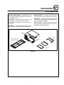
1
MT1820E
CONVEYOR OVEN
INSTALLATION -- OPERATION -- MAINTENANCE
BLODGETT OVEN COMPANY
www.blodgettcorp.com
50 Lakeside Avenue, Box 586, Burlington, Vermont 05402 USA Telephone (800) 331-5842, (802) 860-3700 Fax: (802)864-0183
PN M7260 Rev D (6/01)
E 2000 --- G.S. Blodgett Corporation
IMPORTANT
WARNING: IMPROPER INSTALLATION, ADJUSTMENT,
ALTERATION, SERVICE OR MAINTENANCE CAN CAUSE
PROPERTY DAMAGE, INJURY OR DEATH. READ THE INSTALLATION, OPERATING AND MAINTENANCE INSTRUCTIONS THOROUGHLY BEFORE INSTALLING OR
SERVICING THIS EQUIPMENT
FOR YOUR SAFETY
Do not store or use gasoline or other flammable vapors or
liquids in the vicinity of this or any other appliance.
The information contained in this manual is important for the proper
installation, use, and maintenance of this oven. Adherence to these
procedures and instructions will result in satisfactory baking results
and long, trouble free service. Please read this manual carefully and
retain it for future reference.
Errors: Descriptive, typographic or pictorial errors are subject to correction. Specifications are subject to change without notice.
THE REPUTATION YOU CAN COUNT ON
UNE RÉPUTATION SUR LAQUELLE VOUS POUVEZ COMPTER
For over a century and a half, The Blodgett Oven Company has been building
ovens and nothing but ovens. We’ve set the industry’s quality standard for all
kinds of ovens for every foodservice operation regardless of size, application
or budget. In fact, no one offers more models, sizes, and oven applications
than Blodgett; gas and electric, full-size, half-size, countertop and deck, convection, Cook’n Hold, Combi-Ovens and the industry’s highest quality Pizza
Oven line. For more information on the full line of Blodgett ovens contact your
Blodgett representative.
Model:
Your Service Agency’s Address:
Serial Number:
Your oven was installed by:
Your oven’s installation was checked by:
Table of Contents
Introduction
Oven Description and Specifications . . . . . . . . . . . . . . . . . . . . . . . . . . . . . . . .
Oven Components . . . . . . . . . . . . . . . . . . . . . . . . . . . . . . . . . . . . . . . . . . . . . . .
2
3
Installation
Delivery and Inspection . . . . . . . . . . . . . . . . . . . . . . . . . . . . . . . . . . . . . . . . . . .
Oven Location and Ventilation . . . . . . . . . . . . . . . . . . . . . . . . . . . . . . . . . . . . .
Oven Assembly . . . . . . . . . . . . . . . . . . . . . . . . . . . . . . . . . . . . . . . . . . . . . . . . . .
Utility Connections --- Standards and Codes . . . . . . . . . . . . . . . . . . . . . . . . .
Electrical Connection . . . . . . . . . . . . . . . . . . . . . . . . . . . . . . . . . . . . . . . . . . . . .
4
5
6
9
10
Operation
Safety Information . . . . . . . . . . . . . . . . . . . . . . . . . . . . . . . . . . . . . . . . . . . . . . . .
Oven Operation . . . . . . . . . . . . . . . . . . . . . . . . . . . . . . . . . . . . . . . . . . . . . . . . . .
Oven Adjustments for Cooking . . . . . . . . . . . . . . . . . . . . . . . . . . . . . . . . . . . . .
11
12
13
Maintenance
Cleaning . . . . . . . . . . . . . . . . . . . . . . . . . . . . . . . . . . . . . . . . . . . . . . . . . . . . . . . .
Component Locations . . . . . . . . . . . . . . . . . . . . . . . . . . . . . . . . . . . . . . . . . . . .
Troubleshooting Guide . . . . . . . . . . . . . . . . . . . . . . . . . . . . . . . . . . . . . . . . . . . .
14
15
16
Introduction
Oven Description and Specifications
Cooking in a conveyor oven differs from cooking
in a conventional deck or range oven since heated
air is constantly recirculated over the product by
a fan in an enclosed chamber. The moving air continually strips away the layer of cool air surrounding the product, quickly allowing the heat to penetrate. The result is a high quality product, cooked
at a lower temperature in a shorter amount of time.
Blower
Air Plate
Conveyor
Air Plate
Blodgett conveyor ovens represent the latest advancement in energy efficiency, reliability, and
ease of operation. Heat normally lost, is recirculated within the cooking chamber before being
vented from the oven: resulting in substantial reductions in energy consumption, a cooler kitchen
environment and enhanced oven performance.
Heating
Elements
Air Flow Pattern for Blodgett Conveyor Ovens
Figure 1
MT1820E
SPECIFICATIONS
Belt Width
18” (46 cm)
Cooking Zone Length
20” (51 cm)
Baking Area
2.6 Sq. Ft. (0.24 m2)
Dimensions (single unit)
42” x 32” x 16” (107 cm x 81 cm x 41 cm)
Maximum Input
8.0 KW/Hr.
Maximum Operating Temperature
550_F (288_C)
Power Supply
U.S. and Canadian Installations
208 VAC, 1Φ, 60 Hz, 38.46 Amp
240 VAC, 1Φ, 60 Hz, 33.33 Amp
Export Installations
220 VAC, 1Φ, 50 Hz, 36.36 Amp
230 VAC, 1Φ, 50 Hz, 34.85 Amp
240 VAC, 1Φ, 50 Hz, 33.33 Amp
400 VAC, 3Φ, 50 HZ, L1=16 amps, L2=8 amps,
L3=9.5 amps, N=8 amps
Product Clearance
3.0” (7.62 cm)
2
Introduction
Oven Components
Baking Chamber --- products pass through the
baking chamber on the conveyor belt for cooking.
Conveyor Belt Assembly --- stainless steel chain
link (conveyor) belt and support that carries product through the oven.
Crumb Pan --- catches crumbs from products on
the conveyor. Located under conveyor belt at both
ends of the baking chamber.
Control Box --- contains electrical wiring, cooling
fan or louvers, drive motor and drive chain.
Air Flow Plates --- distribute heated air to top of
baking chamber. Located inside of oven at the top
and bottom of baking chamber.
Drive Motor --- provides power to move the conveyor belt.
Drive Belt --- connects the drive motor sprocket to
the drive side conveyor belt support sprocket.
Control
Box
Product
Stop
Conveyor Assembly
(shown without belt)
Crumb Pans
Figure 2
3
Installation
Delivery and Inspection
The oven can now be moved to the installation
site. Check the following list with Figure 2 on page
3 to be sure all items were received.
All Blodgett ovens are shipped in containers to
prevent damage. Upon delivery of your new oven:
D
D
Inspect the shipping container for external damage. Any evidence of damage should be noted
on the delivery receipt which must be signed by
the driver.
Uncrate the oven and check for internal damage. Carriers will accept claims for concealed
damage if notified within fifteen days of delivery
and the shipping container is retained for inspection.
Part Description
The Blodgett Oven Company cannot assume
responsibility for loss or damage suffered in
transit. The carrier assumed full responsibility
for delivery in good order when the shipment
was accepted. We are, however, prepared to
assist you if filing a claim is necessary.
4
Qty.
Main oven body
1
Conveyor belt assembly
1
Crumb pan
2
Packet containing: 1/2-13 alignment
pins for oven supports
1
Packet containing: flat washers for
oven supports
1
Owner’s manual
1
Product stop (available in 0” or 12”)
1
Installation
Oven Location and Ventilation
LOCATION
VENTILATION
The well planned and proper placement of your
oven will result in long term operator convenience
and satisfactory performance.
U.S. and Canadian installations
Refer to your local ventilation codes. In the absence of local codes, refer to the National ventilation code titled, “Standard for the Installation of
Equipment for the Removal of Smoke and Grease
Laden Vapors from Commercial Cooking Equipment”, NFPA-96-Latest Edition.
The following clearances must be maintained between the oven and any combustible or non-combustible construction.
D
D
Oven body sides --- 16” (41cm)
Oven body back --- 0” (0cm)
General export installations
The following clearances must be available for servicing.
D
D
Installation must conform with Local and National
installation standards. Local installation codes
and/or requirements may vary. If you have any
questions regarding the proper installation and/or
operation of your Blodgett oven, please contact
your local distributor. If you do not have a local distributor, please call the Blodgett Oven Company at
0011-802-860-3700.
Oven body left side --- 38” (97cm)
Oven body back --- 28” (71cm)
Oven models having casters can be rolled away
from the wall for servicing. If the oven needs to be
moved further from the wall, power must first be
turned off and disconnected from the oven.
D
D
D
D
Place the oven in an area that is free of drafts.
Keep the oven area free and clear of all combustibles such as paper, cardboard, and flammable
liquids and solvents.
Do not place the oven on a curb base or seal to
a wall.
Tripping the blower motor’s thermal overload
device indicates an excessive ambient temperature at the back of the oven. This condition
must be corrected to prevent permanent damage to the oven. All motor bearings are permanently lubricated by the manufacturer. There is
no need for additional lubrication during the operational lifetime of the motors.
WARNING:
Failure to properly vent the oven can be
hazardous to the health of the operator
and may result in operational problems,
unsatisfactory baking and possible damage to the equipment.
Damage sustained as a direct result of improper ventilation will not be covered by
the Manufacturer’s warranty.
5
Installation
Oven Assembly
LEGS
OVEN STAND WITH CASTERS
1. Lay the oven on it’s back. Screw one leg into
each of the four holes located on the bottom
of the oven chamber.
2. Tighten the hex nut at the top of each leg.
3. Lift the oven upright onto the legs.
1. Attach each leg to the stand frame with a lock
washer and nut. DO NOT tighten completely.
2. Position the shelf between the legs with the
smooth surface facing the top of the stand.
Align the shelf with the holes in each leg. Attach the shelf to each leg with a nut and bolt.
3. Tighten the bolts installed in step 1.
4. Place the oven onto the stand. Bolt the oven
to the stand from underneath.
Bottom of
Oven
Leg
Stand
Frame
Top of
Stand
Figure 3
Shelf
Figure 4
6
Installation
Oven Assembly
STACKING THE OVENS
Bottom Oven
2. Attach the heat shield brackets to the bottom
of the control box of the upper oven with the
screws provided.
3. Carefully lift the upper oven off the pallet and
place it on the lower oven. Be sure the alignment pins are inserted into the holes in the top
of the lower oven.
4. Slide the heat shield into the brackets.
1. Install the legs, as directed.
2. Attach the stacking rail to the back of the control compartment.
Top Oven(s)
1. Rest the oven on it’s back. Install an oven
alignment pin into each of the four holes in the
bottom of the oven.
Heat Shield
Heat Shield
Brackets
Stacking Rail
Alignment Pin
Top Oven
Bottom Oven
Figure 5
7
Installation
Oven Assembly
CONVEYOR
1. Slide the conveyor assembly through the left
hand tunnel opening until the sprocket is inside the control box. See Figure 6.
2. Install the drive belt on the motor and then
around the pulley on the conveyor assembly.
See Figure 7. Pull the conveyor assembly
back to tighten the belt.
Unless specified otherwise, conveyor travel is factory set for left to right operation when facing the
front of the oven. To reverse the direction of the
drive motor (if necessary), exchange A1 and A2.
WARNING!!
Disconnect the power supply before reversing the drive motor.
CRUMB PANS
1. Install the crumb pans on both ends of the
conveyor.
Figure 6
Figure 8
Figure 7
8
Installation
Utility Connections --- Standards and Codes
U.S. and Canadian installations
THE INSTALLATION INSTRUCTIONS CONTAINED HEREIN ARE FOR THE USE OF QUALIFIED INSTALLATION AND SERVICE PERSONNEL
ONLY. INSTALLATION OR SERVICE BY OTHER
THAN QUALIFIED PERSONNEL MAY RESULT IN
DAMAGE TO THE OVEN AND/OR INJURY TO
THE OPERATOR.
All ovens, when installed, must be electrically
grounded in accordance with local codes, or in the
absence of local codes, with the National Electrical
Code, ANSI/NFPA 70 ---Latest Edition and/or Canadian National Electric Code C22.2 as applicable.
General export installations
Qualified installation personnel are individuals, a
firm, a corporation, or a company which either in
person or through a representative are engaged
in, and responsible for:
Installation must conform with Local and National
installation standards. Local installation codes
and/or requirements may vary. If you have any
questions regarding the proper installation and/or
operation of your Blodgett oven, please contact
your local distributor. If you do not have a local distributor, please call the Blodgett Oven Company at
0011-802-860-3700.
the installation of electrical wiring from the electric meter, main control box or service outlet to
the electric appliance.
Qualified installation personnel must be experienced in such work, familiar with all precautions
required, and have complied with all requirements
of state or local authorities having jurisdiction.
D
9
Installation
Electrical Connection
Before making any electrical connections to this
unit, check that the power supply is adequate for
the voltage, amperage, and phase requirements
stated on the rating plate.
A wiring diagram accompanies this manual and is
also attached to the inside of the control box.
L1
Supply
L2
208/240
Oven
U.S. and Canadian installations
Electrically-fired models are equipped for operation
on 208 or 240VAC, 1Φ, 60Hz, 2 wire grounded circuits. The oven is equipped with a 50 amp cord set.
U.S. and Canadian Installations
General export installations
The export models are available in either single or
three phase. The single phase oven is equipped
for operation on 220, 230 or 240 VAC, 50HZ., 2
wire grounded circuits. The three phase units are
equipped for operation on 400 VAC, 50HZ, 4 wire
grounded circuits. Wiring from the power source
to any of these units must be a minimum of #10
AWG (5.26 mm2) copper stranded wire or larger.
L1
Supply
L2
220/230/240
Oven
Single Phase Ovens
L1
WARNING!!
L2
Incorrect single phase wiring will result in
extensive damage to electrical components and possible fire in the control box.
THE BLODGETT OVEN COMPANY CANNOT ASSUME RESPONSIBILITY FOR LOSS OR DAMAGE
SUFFERED AS A RESULT OF IMPROPER INSTALLATION.
Supply
400
L3
Three Phase Ovens
General Export Installations
Figure 9
10
Oven
Operation
Safety Information
THE INFORMATION CONTAINED IN THIS SECTION IS PROVIDED FOR THE USE OF QUALIFIED
OPERATING PERSONNEL. QUALIFIED OPERATING PERSONNEL ARE THOSE WHO HAVE
CAREFULLY READ THE INFORMATION CONTAINED IN THIS MANUAL, ARE FAMILIAR WITH
THE FUNCTIONS OF THE OVEN AND/OR HAVE
HAD PREVIOUS EXPERIENCE WITH THE OPERATION OF THE EQUIPMENT DESCRIBED. ADHERENCE TO THE PROCEDURES RECOMMENDED HEREIN WILL ASSURE THE
ACHIEVEMENT OF OPTIMUM PERFORMANCE
AND LONG, TROUBLE-FREE SERVICE.
Please take the time to read the following safety
and operating instructions. They are the key to the
successful operation of your Blodgett conveyor
oven.
11
SAFETY TIPS
For your safety read before operating
General safety tips:
D
D
If the oven needs to be moved for any reason,
the supply cord must be disconnected from the
unit before removing the restraint cable. Reconnect the restraint after the oven has been returned to its original location.
DO NOT remove the control box cover unless
the oven is unplugged.
Operation
Oven Operation
CONTROLS DESCRIPTION
HEAT INDICATOR light (2) cycles on and off
with the demand for heat.
3. Press and hold the arrow keys on the COOK
TIME CONTROL (4) to set the desired cook
time. Use the up arrow key to increase the
time and the down arrow key to decrease the
time. The cook time range for this unit is 1---12
minutes.
Oven Shut Down:
1. ON/OFF SWITCH --- Controls power to the
oven.
2. HEAT INDICATOR LIGHT ---When lit indicates
the elements are operating.
3. TEMPERATURE CONTROL --- Used to set desired cook temperature.
4. COOK TIME CONTROL --- Used to set the desired cook time.
1. Turn the ON/OFF switch (1) to OFF. The blower
motors and cooling fans will run for 45 minutes
until the oven cools down.
OPERATION
Oven Start Up:
Cool Down Circuit:
1. Turn the ON/OFF switch (1) to ON.
2. Rotate the TEMPERATURE CONTROL knob
(3) to set the desired cook temperature. The
The blower motor and controls are protected by
thermal switches which will turn on the cooling
fans if the control compartments get too warm.
4
1
2
3
Figure 10
12
Operation
Oven Adjustments for Cooking
The combination of belt time, oven temperature,
and air flow are important for achieving quality results from your Blodgett conveyor oven. Use the
following guidelines to adjust the belt time and
oven temperature of your unit. For questions regarding further oven adjustments, please contact
your local Blodgett Sales Representative for assistance.
CONVEYOR SPEED AND OVEN TEMPERATURE
Conveyor belt speed (cook time) and oven temperature are the two variables used when fine tuning your oven for a specific product. To determine
the optimum bake time and temperature, make
small changes for each trial and keep one variable
constant. For example, if the oven temperature is
460_F (238_C) and the belt speed is 7 minutes,
but the pizza is not browned enough, increase the
temperature to 475_F (246_C) and keep the belt
speed the same. However, if the center of the pizza
is not completely cooked, keep the oven temperature the same, and increase the bake time to 7
minutes and 30 seconds. In general, raise the
bake temperature to increase browning, and
lengthen the bake time to increase doneness.
13
FINISHED PRODUCT TEMPERATURES
Internal temperatures of the cooked products
should be measured immediately after the product exits the cooking chamber to ensure a safe
food temperature. Internal pizza temperatures
should be over 165_F (74_C). Minimum temperature guidelines vary depending on the food items.
Maintenance
Cleaning
Follow this recommended cleaning schedule for
proper oven performance.
Daily:
1. Clean the conveyor belt using a wire brush. Allow any foreign material to drop into the crumb
pans.
2. Empty and clean the crumb pans.
Every Three Months:
1. Brush and clean the guards of the cooling fans.
Every Six Months:
The inside of the oven should be cleaned to remove anything that could have dropped off the
conveyor belt and possibly blocked some of the
air flow holes.
1. Remove the conveyor assembly as follows:
a.) Remove the drive belt from the conveyor
assembly pulley and the drive motor.
b.) Slide the conveyor assembly out of the
oven cavity from the left side of the oven.
2. Remove the air plates as follows:
a.) Remove the panel over the conveyor tunnel on the exit end of the oven.
b.) Slide the upper and lower air plates out of
the oven.
Figure 11
3. Clean the conveyor assembly, air plates and
oven interior with an appropriate oven cleaner
safe for aluminum.
4. Reinstall the air plates and conveyor assembly.
NOTE: The air plate marked TOP must be
placed above the conveyor assembly.
The air plate marked BOTTOM must be
placed below the conveyor assembly.
14
Every 12 Months:
A factory authorized service person should:
1. Open and clean the inside of the control panel
and control box.
2. Check and tighten all electrical connections.
3. Check conveyor drive belt for cleanliness.
If maintenance is required contact your local service company, a factory representative or the
Blodgett Oven company.
WARNING!!
Always disconnect the power supply before cleaning or servicing the oven.
Maintenance
Component Locations
Cooling Fans
S.S. Relay
Conveyor Motor
Drive Belt
Power Supply
Connection
Fuses
Figure 12
15
High Limit
Reset Button
Maintenance
Troubleshooting Guide
POSSIBLE CAUSE(S)
SUGGESTED REMEDY
SYMPTOM: Blower motor(s) not running
S
S
S
S
Power switch turned OFF
S
S
S
S
No power to oven
Bad capacitor
Motor(s) burned out
Turn to ON position
Replace main fuses or reset breakers
Replace capacitor
*
SYMPTOM: Oven will not heat (heat on light will not come on).
S Temperature controller not properly installed
S Reinstall
S Internal problem with main temperature controller S *
S Loose probe connections at main temperature S *
controller
S Short in probe
S *
SYMPTOM: Elements will not heat.
S Power switch turned OFF
S Main temperature controller not set above
S Turn to ON position
S Set to desired temperature
S Defective heating relay
S *
S *
ambient temperature
S Defective main temperature controller
*Denotes remedy is a difficult operation and should be performed by qualified personnel only. It is recommended, however, that
All repairs and/or adjustments be done by your local Blodgett service agency and not by the owner/operator. Blodgett cannot assume responsibility for damage as a result of servicing done by unqualified personnel.
WARNING!!
Always disconnect the power supply before cleaning or servicing the oven.
16
Maintenance
Troubleshooting Guide
POSSIBLE CAUSE(S)
SUGGESTED REMEDY
SYMPTOM: Oven will not reach desired temperature
S
S
S
S
S
S
S
No power to oven
S
Blower motor(s) not running
S
Defective heating element relay
S
Shorted probe
S
Heating element(s) burned out
S
Internal problem with main temperature controller S
Cooling fan not working properly
S
Replace main fuses
Check control switch and/or fuses
*
*
*
*
*
SYMPTOM: Conveyor belt will not run
S
S
S
S
Control circuit fuse blown
S
S
S
S
Belt hooked on something in oven
Defective conveyor drive motor
Defective conveyor drive motor controller
Replace fuse
Turn oven OFF. Unhook and resolve problem
*
*
*Denotes remedy is a difficult operation and should be performed by qualified personnel only. It is recommended, however, that
All repairs and/or adjustments be done by your local Blodgett service agency and not by the owner/operator. Blodgett cannot assume responsibility for damage as a result of servicing done by unqualified personnel.
WARNING!!
Always disconnect the power supply before cleaning or servicing the oven.
17
CUSTOMER
INSERT
WIRING DIAGRAM
HERE