Download Eurotech VIPER-Lite Datasheet
Transcript
31 VIPER / VIPER-Lite PXA255 RISC based PC/104 Single Board Computer Technical Manual VIPER Technical Manual Definitions Eurotech is the trading name for Eurotech Ltd. Disclaimer The information in this manual has been carefully checked and is believed to be accurate. Eurotech assumes no responsibility for any infringements of patents or other rights of third parties, which may result from its use. Eurotech assumes no responsibility for any inaccuracies that may be contained in this document. Eurotech makes no commitment to update or keep current the information contained in this manual. Eurotech reserves the right to make improvements to this document and/or product at any time and without notice. Warranty This product is supplied with a 3 year limited warranty. The product warranty covers failure of any Eurotech manufactured product caused by manufacturing defects. The warranty on all third party manufactured products utilized by Eurotech is limited to 1 year. Eurotech will make all reasonable effort to repair the product or replace it with an identical variant. Eurotech reserves the right to replace the returned product with an alternative variant or an equivalent fit, form and functional product. Delivery charges will apply to all returned products. Please check www.eurotech-ltd.co.uk/support for information about Product Return Forms. Trademarks ARM and StrongARM are registered trademarks of ARM Ltd. Intel and XScale are trademarks or registered trademarks of Intel Corporation or its subsidiaries in the United States and other countries. Windows CE is a trademark of the Microsoft Corporation. CompactFlash is the registered trademark of SanDisk Corp. Linux is a registered trademark of Linus Torvalds. RedBoot and Red HatTM is a registered trademark of Red Hat Inc. VxWorks is a register trademark of Wind River. Bluetooth is a registered trademark of Bluetooth SIG, Inc. All other trademarks recognised. Revision History Manual PCB Date Comments Issue A V2 Issue 3 29th June 2005 First full release of Manual for VIPER Version 2. th Issue B V2 Issue 4A 9 August 2006 Updated to include VIPER-Lite details, support for Intel P30 Flash and for full RoHS-6 compliance. Issue C V2 Issue 4A 25th January 2007 Updated to show USB cables with Type A Plugs used to connect to USB Host and Client connectors PL7 and PL17 respectively. Issue D V2 Issue 4A 25th April 2007 Updated to show RS422/485 termination resistor jumpers disconnected as default Issue E V2 Issue 4A 1st October 2007 Minor updates, Eurotech rebranding. © 2007 Eurotech Ltd. For contact details, see page 101. ISO 9001 FM12961 VIPER Technical Manual Contents Contents Introduction ........................................................................................................................................4 VIPER ‘at a glance’................................................................................................................5 VIPER-Lite ‘at a glance’ .........................................................................................................6 VIPER features ......................................................................................................................7 VIPER support products ........................................................................................................9 Product handling and environmental compliance ................................................................12 Conventions .........................................................................................................................13 Getting started .................................................................................................................................15 Using the VIPER ..................................................................................................................15 Detailed hardware description .........................................................................................................18 VIPER block diagram...........................................................................................................18 VIPER address map ............................................................................................................19 Translations made by the MMU ...........................................................................................20 PXA255 processor...............................................................................................................21 PXA255 GPIO pin assignments...........................................................................................22 Real time clock ....................................................................................................................26 Watchdog timer....................................................................................................................26 Memory ................................................................................................................................27 Interrupt assignments ..........................................................................................................30 Flat panel display support ....................................................................................................34 Audio....................................................................................................................................56 General purpose I/O ............................................................................................................57 USB host interface ...............................................................................................................60 USB client interface .............................................................................................................61 10/100BaseTX Ethernet ......................................................................................................62 Serial COMs ports................................................................................................................64 PC/104 interface ..................................................................................................................67 2 I C ........................................................................................................................................71 TPM .....................................................................................................................................71 JTAG and debug access......................................................................................................72 Power and power management .......................................................................................................73 Power supplies ....................................................................................................................73 Power management.............................................................................................................74 Connectors, LEDs and jumpers .......................................................................................................85 Connectors ..........................................................................................................................86 Status LEDs .........................................................................................................................97 Jumpers ...............................................................................................................................98 Appendix A – Contacting Eurotech ................................................................................................101 Appendix B – Specification ............................................................................................................102 Appendix C – Mechanical diagram ................................................................................................103 Appendix D – Reference information .............................................................................................104 Appendix E – Acronyms and abbreviations ...................................................................................106 Appendix F – RoHS-6 Compliance - Materials Declaration Form..................................................108 Index ..............................................................................................................................................109 © 2007 Eurotech Ltd Issue E 3 VIPER Technical Manual Introduction Introduction The VIPER is an ultra low power, PC/104 compatible, single board computer available in two standard variants: • VIPER, based on the 400MHz PXA255 XScale processor. • VIPER-Lite, based on the 200MHz PXA255 XScale processor. The PXA255 is an implementation of the Intel XScale micro architecture combined with a comprehensive set of integrated peripherals including: a flat panel graphics controller, interrupt controller, real time clock and multiple serial ports. The VIPER board offers a wide range of features making it ideal for power sensitive embedded communications and multimedia applications. Both of the standard variants are available in two memory configurations, as shown below: Variant Memory configuration Details VIPER VIPER-M64-F32-V2-R6 PXA255 400MHz microprocessor, 64MB SDRAM, 32MB FLASH. VIPER-M64-F16-V2-R6 PXA255 400MHz microprocessor, 64MB SDRAM, 16MB FLASH. VIPERL-M64-F32-V2-R6 PXA255 200MHz microprocessor, 64MB SDRAM, 32MB FLASH, with reduced functionality. VIPERL-M64-F16-V2-R6 PXA255 200MHz microprocessor, 64MB SDRAM, 16MB FLASH, with reduced functionality. VIPER-Lite The VIPER and VIPER-Lite variants are also available in an industrial temperature range. Please contact our Sales team (see Appendix A – Contacting Eurotech, page 101) for availability. The following features are not available on the standard VIPER-Lite configuration: • PC/104 bus. • USB host controller. • Audio codec. • COM4, COM5 serial ports. • TPM (trusted platform module). • SRAM (static random access memory). Eurotech Ltd can provide custom configurations (subject to a minimum order quantity) for the VIPER or the VIPER-Lite. Please contact our Sales team (see Appendix A – Contacting Eurotech, page 101) to discuss your requirements. © 2007 Eurotech Ltd Issue E 4 VIPER Technical Manual Introduction VIPER ‘at a glance’ Five Serial Ports Jumpers Audio – In/Out/MIC/AMP 10/100BaseTX Ethernet Ethernet LEDs Power (inc reset input) Battery TPM Tamper (optional) 400MHz PXA255 processor 8/16-bit PC/104 interface JTAG Intel StrataFLASH Jumpers USB Client Digital I/O USB TFT/STN panel © 2007 Eurotech Ltd Issue E CompactFLASH (CF+) 5 VIPER Technical Manual Introduction VIPER-Lite ‘at a glance’ Three Serial Ports 10/100BaseTX Ethernet Ethernet LEDs Power (inc reset input) Battery 200MHz PXA255 processor JTAG Intel StrataFLASH Jumpers USB Client Digital I/O TFT/STN panel © 2007 Eurotech Ltd Issue E CompactFLASH (CF+) 6 VIPER Technical Manual Introduction VIPER features Microprocessor • PXA255 400MHz (VIPER) or 200MHz (VIPER-Lite) RISC processor. • 32K data cache, 32K instruction cache, 2K mini data cache. • 64MB un-buffered 3.3V SDRAM. • Up to 16/32MB Intel StrataFLASH (with FLASH access LED). • 1MB bootloader FLASH EPROM (with FLASH access LED). • 256KB SRAM (battery backed). • Type I/II CompactFLASH (CF+) socket. • TFT/STN (3.3V or 5V) flat panel graphics controller. • Up to 640X480 resolution. • 8/16bpp. • Backlight control. VL • National Semiconductor LM4529 AC’97 CODEC and LM4880 power amp. VL • Line IN, line OUT, microphone and 250mW per channel amplified output. • 5 x 16550 compatible high-speed UARTs. • 4 x RS232 and 1 x RS422/485 Interfaces. • 2 x channels with 128Byte Tx/Rx FIFO. • • Two USB 1.1 compliant interfaces. Short circuit protection and 500mA current limit protection. • One USB 1.1 client interface. Cache System memory Silicon disk VL Video Audio Serial ports 1 0F USB host interface VL USB client interface 1 COM4 (RS232) and COM5 (RS422/485) are not available on the VIPER-Lite. © 2007 Eurotech Ltd Issue E 7 VIPER Technical Manual Introduction Network support • • SMSC LAN91C111 10/100BaseTX Ethernet controller. One 10/100BaseTX NIC port. Trusted Platform Module (TPM) [optional] VL • Atmel AT97SC3201 TPM security, with full TCG/TCPA V1.1b compatibility. VL • Includes crypto accelerator capable of computing a 1024-bit RSA signature in 100ms. • Battery backed RTC. • ± 1minute/month accuracy, at 25°C. • Adjustable timeout of 271ns to 19 minutes 25 seconds. Real time clock (RTC) Watchdog General purpose I/O (GPIO) User configuration Expansion VL JTAG port Power • • 8 x 3.3V tolerant inputs (5V tolerant). 8 x 3.3V outputs. • 1 user-configurable jumper. • PC/104 expansion bus - 8/16-bit ISA bus compatible interface. • • Download data to FLASH memory. Debug and connection to In-Circuit Emulator (ICE). • • Typically 2W from a single 5V supply. Power management features allowing current requirements to be as low as 49mA (245mW). • Onboard battery holder containing a lithium-ion non-rechargeable CR2032, 3V, 220mAh battery. • PC/104 compatible footprint 3.8” x 3.6” (96mm x 91mm). • Operating temperature range: Battery backup Size Environmental - Commercial: -20oC (-4oF) to +70oC (+158oF) - Industrial: • © 2007 Eurotech Ltd Issue E -40oC (-40oF) to +85oC (+185oF) RoHS directive (2002/95/EC) compliant 8 VIPER Technical Manual Introduction VIPER support products The VIPER supports the following products: • VIPER-UPS (Uninterruptible Power Supply) The VIPER-UPS serves as a 5V DC power supply and battery back up system for the VIPER. The UPS accepts between 10 – 36 VDC (10-25VAC) input and generates the +5V supply for the VIPER. In addition to this, it includes an intelligent battery charger/switch capable of using either the onboard 500mAHr NiMH battery or an external sealed lead acid rechargeable battery. For further details, see www.eurotech-ltd.co.uk/products/icp/pc104/processors/viper_UPS.htm. 15H • VIPER-FPIF1 (Flat Panel Interface) The VIPER-FPIF1 is a simple board that enables easy connection between the VIPER and an LCD flat panel. See the section VIPER-FPIF1 details, page 38, for further details. Contact Eurotech Ltd (see Appendix A – Contacting Eurotech, page 101) for purchasing information. 214H 215H 16H72 217H • ETHER-BREAKOUT The ETHER-BREAKOUT is a simple board that converts the VIPER Ethernet 8-pin header and Ethernet LEDs 6-pin header to a standard RJ45 connector with LEDs. Contact Eurotech Ltd (see Appendix A – Contacting Eurotech, page 101) for purchasing information. 18H92 • 219H FPIF-LVDS-TX (Flat Panel Interface) The FPIF-LVDS-TX enables LVDS displays to be connected to the VIPER. The FPIF-LVDS-TX in combination with the FPIF-LVDS-RX allows the VIPER to drive a TFT or STN LCD flat panel display up to 10 meters away. See the section FPIFLVDS-TX details, page 43, for further details. Contact Eurotech Ltd (see Appendix A – Contacting Eurotech, page 101) for purchasing information. 20H 21H 20H1 23H • FPIF-LVDS-RX (Flat Panel Interface) The FPIF-LVDS-RX in combination with the FPIF-LVDS-TX allows the VIPER to drive a TFT or STN LCD flat panel display up to 10 meters away. See the section FPIF-LVDS-RX details, page 48, for further details. Contact Eurotech Ltd (see Appendix A – Contacting Eurotech, page 101) for purchasing information. 24H 25H 23H46 • 27H FPIF-CRT (CRT Monitor or Analogue FPD Interface) The FPIF-CRT is a simple board that enables easy connection between the VIPER and a CRT Monitor or analogue LCD flat panel. See the section FPIF-CRT details, page 53, for further details. Contact Eurotech Ltd (see Appendix A – Contacting Eurotech, page 101) for purchasing information. 28H 29H 25H630 231H • VIPER-I/O VIPER-I/O is a low cost add-on I/O module for the PXA255 VIPER board. The board provides a variety of I/O features without the additional costs of a full PC/104 interface. The combination of the VIPER and VIPER–I/O is suited to control and monitoring applications that require a limited number of isolated inputs and outputs. See the section VIPER-I/O, page 59, for further details. Contact Eurotech Ltd (see Appendix A – Contacting Eurotech, page 101) for purchasing information. 23H 27H8934 © 2007 Eurotech Ltd 23H 235H Issue E 9 VIPER Technical Manual Introduction • CYCLOPS The CYCLOPS is a rugged VIPER display terminal. The enclosure can be configured to suit a complete range of embedded applications with LCD display and touchscreen. • VIPER-ICE (Industrial Compact Enclosure) development kits The VIPER-ICE is a simple low cost aluminium enclosure, which provides easy connection to all on board features. The enclosure includes the VIPER-UPS and optionally a colour Q-VGA (320x240) TFT flat panel display and analogue touchscreen. The VIPER-ICE is available with a wide range of development kits. These are described in the section Development kits available for the VIPER, page 10. For further details, see www.eurotech-ltd.co.uk/development-kits.htm. 236H 237H 30H Development kits available for the VIPER • Windows CE/CE 5.0 development kit Features of this kit are: - 400MHz PXA255 processor with 64MB DRAM & 32MB Flash memory. - Pre-configured build of Windows CE 5.0 tailored specifically for the VIPER, preloaded into the 32MB Flash. - Windows CE 5.0 Platform SDK for VIPER. - Rugged enclosure with NEC Q-VGA TFT colour 5.5 and display and analogue touchscreen. - Uninterruptible power supply (VIPER-UPS) to allow VIPER system to continue to operate without main power. Example code is supplied to handle the power loss warning and battery backup control features. - 24V power supply module with power cords for US, UK and European power sockets. - Eurotech Ltd Development Kit CD containing Windows CE 5.0 operating system image, sample code, Technical Manual and datasheets. - Quickstart manual. 31H 32H • Embedded Linux development kit Features of this kit are: - 400MHz PXA255 processor with 64MB DRAM & 32MB Flash memory. - Pre-configured build of Eurotech Ltd’s Embedded Linux, tailored specifically for the VIPER, pre-loaded into the 32MB Flash. - 2.6-based Linux kernel release, GNU C library. - Compressed Journaling Flash File System (JFFS2) offering high reliability and recovery from power interruptions. - Rugged enclosure with optional NEC Q-VGA TFT colour display and analogue touchscreen. - Uninterruptible power supply (VIPER-UPS) to allow VIPER system to continue to operate without main power. - 24V power supply module with power cords for US, UK and European power sockets. - Optional - high performance IBM J9 VM. - Quickstart tutorial guide. 3H 34H © 2007 Eurotech Ltd Issue E 10 VIPER Technical Manual • Introduction Wind River VxWorks 5.5 development kit Features of this kit are: - 400MHz PXA255 processor with 64MB DRAM & 32MB Flash memory. - VxWorks BSP for Tornado 2.2.1/VxWorks 5.5.1/Wind ML 3.0.2. - Pre-configured build of VxWorks, tailored specifically for the VIPER, pre-loaded into the 32MB Flash. - Rugged enclosure with optional NEC Q-VGA TFT colour display and analogue touchscreen. - Uninterruptible power supply (VIPER-UPS) to allow VIPER system to continue to operate without main power. - 24V power supply module with power cords for US, UK and European power sockets. 35H 36H Entry level development kits for VIPER or VIPER-Lite The following entry level development kits are available: • Windows CE / CE 5.0 development kit Features of this kit for VIPER or VIPER-Lite are: - 400MHz (VIPER) or 200MHz (VIPER-Lite) PXA255 processor with 64MB DRAM & 32MB Flash memory. - Pre-configured build of Windows CE 5.0 tailored specifically for the VIPER, preloaded into the 32MB Flash. - +5V PSU. - All cables for immediate operation and download. - Development kit documentation. - Optional VIPER-I/O module. • Embedded Linux development kit Features of this kit for VIPER or VIPER-Lite are: - 400MHz (VIPER) or 200MHz (VIPER-Lite) PXA255 processor with 64MB DRAM & 32MB Flash memory. - Pre-configured build of Eurotech Ltd’s Embedded Linux, tailored specifically for the VIPER, pre-loaded into the 32MB Flash. - +5V PSU. - All cables for immediate operation and download. - Development kit documentation. - Optional VIPER-I/O module. © 2007 Eurotech Ltd Issue E 11 VIPER Technical Manual Introduction Product handling and environmental compliance Anti-static handling This board contains CMOS devices that could be damaged in the event of static electricity discharged through them. At all times, please observe anti-static precautions when handling the board. This includes storing the board in appropriate anti-static packaging and wearing a wrist strap when handling the board. Packaging Please ensure that should a board need to be returned to Eurotech Ltd, it is adequately packed, preferably in the original packing material. Electromagnetic compatibility (EMC) The VIPER is classified as a component with regard to the European Community EMC regulations and it is the users responsibility to ensure that systems using the board are compliant with the appropriate EMC standards. RoHS Compliance The European RoHS Directive (Restriction on the use of certain Hazardous Substances – Directive 2002/95/EC) limits the amount of 6 specific substances within the composition of the product. The VIPER, VIPER-Lite and associated accessory products are available as RoHS-6 compliant options and are identified by a -R6 suffix in the product order code. A full RoHS Compliance Materials Declaration Form is included in Appendix F – RoHS-6 Compliance - Materials Declaration Form, page 108. Further information about RoHS compliance is available on the Eurotech Ltd web site – www.eurotech-ltd.co.uk/RoHS_and_WEEE. 238H 239H 37H © 2007 Eurotech Ltd Issue E 12 VIPER Technical Manual Introduction Conventions Symbols The following symbols are used in this guide: Symbol Explanation Note - information that requires your attention. Tip - a handy hint that may provide a useful alternative or save time. Caution - proceeding with a course of action may damage your equipment or result in loss of data. VL Indicates that a feature is not available on the standard VIPER-Lite configuration. Eurotech Ltd can provide custom configurations (subject to a minimum order quantity) for the VIPER-Lite populated with this feature. Please contact our Sales team (see Appendix A – Contacting Eurotech, page 101) to discuss your requirements. 240H 241H Jumper is fitted. Jumper is not fitted. © 2007 Eurotech Ltd 3 2 1 Jumper fitted on pins 1-2. 3 2 1 Jumper fitted on pins 2-3. Issue E 13 VIPER Technical Manual Introduction Tables With tables such as that shown below, the white cells show information relevant to the subject being discussed. Grey cells are not relevant in the current context. Byte lane Bit Most Significant Byte Least Significant Byte 15 14 13 12 11 10 9 8 7 6 5 4 3 Field - - - - - - - - - - - - - Reset X X X X X X X X 0 0 0 0 0 2 1 0 RETRIG AUTO_ R_DIS CLR 0 0 0 Relevant information © 2007 Eurotech Ltd Issue E 14 VIPER Technical Manual Getting started Getting started Depending on the development kit purchased, a Quickstart Manual is provided for Windows CE, embedded Linux or VxWorks to enable users to set-up and start using the board. Please read the relevant manual and follow the steps defining the set-up of the board. Once you have completed this task you will have a working VIPER system and can start adding further peripherals enabling development to begin. This section provides a guide to setting up and using of some of the features of the VIPER. For more detailed information on any aspect of the board see Detailed hardware description, page 18. 24H 243H Using the VIPER Using the CompactFLASH™ socket The VIPER is fitted with a Type I/II CompactFLASH socket mounted on the topside of the board. The socket is connected to Slot 0 of the PXA255 PC card interface. It supports 3.3V Type I and II CompactFLASH cards for both memory and IO. The VIPER supports hot swap changeover of the cards and notification of card insertion. RedBoot supports ATA type CompactFlash cards. Files can be read providing the card is formatted with an EXT2 file system. Eboot cannot boot from CompactFlash. 5V CompactFLASH is not supported. The CompactFLASH card can only be inserted one way into the socket. The correct orientation is for the top of the card, i.e. with the normal printed side face down to the PCB. Using the serial interfaces (RS232/422/485) The five serial port interfaces on the VIPER are fully 16550 compatible. Connection to the serial ports is made via a 40-way boxed header. The pin assignment of this header has been arranged to enable 9-way IDC D-Sub plugs to be connected directly to the cable. See the section PL4 – COMS ports, page 89, for pin assignment and connector details. 38H 24H A suitable cable for COM1 is provided as part of the development kit. The D-Sub connector on this cable is compatible with the standard 9-way connector on a desktop computer. VL COM4 (RS232) and COM5 (RS422/485) are not available on the standard VIPER-Lite configuration. Eurotech Ltd can provide custom configurations (subject to a minimum order quantity) for the VIPER-Lite populated with this feature. Please contact our Sales team (see Appendix A – Contacting Eurotech, page 101) to discuss your requirements. 245H 246H © 2007 Eurotech Ltd Issue E 15 VIPER Technical Manual Getting started Using the audio features There are four audio interfaces supported on the VIPER: amp out, line out, line in and microphone. The line in, line out and amp interfaces support stereo signals and the microphone provides a mono input. The amplified output is suitable for driving an 8Ω load with a maximum power output of 250mW per channel. Connections are routed to PL6 - see the sections Audio (page 56) and PL6 – Audio connector (page 91) for further details. VL 39H 247H 40H 248H Using the USB host VL The standard USB connector is a 4-way socket, which provides power and data signals to the USB peripheral. The 10-way header PL7 has been designed to be compatible with PC expansion brackets that support two USB sockets. See the sections USB host interface (page 60) and PL7 – USB connector (page 91) for further details. 249H 250H 251H 25H Using the USB client The VIPER board can be used as USB client and connected to a PC via a USB cable. The USB cable should be plugged into PL17 header. See the sections USB client interface (page 61) and PL17 – USB client connector (page 95) for further details. 253H 254H 25H 256H Using the Ethernet interface The SMSC LAN91C111 10/100BaseTX Ethernet controller is configured by the RedBoot bootloader for embedded Linux or VxWorks, and by Eboot for Windows CE. Connection is made via connector PL1. A second connector PL2 provides activity and link status outputs for control LEDs. See the sections 10/100BaseTX Ethernet (page 62), PL1 – 10/100BaseTX Ethernet connector (page 87) and PL2 – Ethernet status LEDs connector (page 87) for further details. 257H 258H 259H 260H 261H 26H The Ethernet port may be connected to an ETHER-BREAKOUT module to provide a standard RJ45 port connector, see section Ethernet breakout board, page 62 for further details. 263H © 2007 Eurotech Ltd Issue E 264H 16 VIPER Technical Manual Getting started Using the PC/104 expansion bus VL PC/104 modules can be used with the VIPER to add extra functionality to the system. This interface supports 8/16 bit ISA bus style peripherals. Eurotech Ltd has a wide range of PC/104 modules, which are compatible with the VIPER. These include modules for digital I/O, analogue I/O, motion control, CAN bus, serial interfaces, etc. Please contact the Eurotech Ltd sales team if a particular interface you require does not appear to be available as these modules are in continuous development. Contact details are provided in Appendix A – Contacting Eurotech, page 101. 41H265 26H In order to use a PC/104 board with the VIPER it should be plugged into PL11 for 8-bit cards and PL11/PL12 for 8/16-bit cards. See the sections PC/104 interface (page 67) and PL11 & PL12 – PC/104 connectors (page 94) for further details. 267H 42H 268H 269H The ISA interface on the VIPER does not support DMA or shared interrupts. See the section Interrupt assignments, page 30, for details about PC/104 interrupt use. 43H 270H The VIPER provides +5V to a PC/104 add-on board via the PL11 and PL12 connectors. If a PC/104 add-on board requires a +12V supply, then +12V must be supplied to the VIPER power connector PL16 pin 4. If –12V or –5V are required, these must be supplied directly to the PC/104 add-on board. The VIPER is available with non-stack through connectors by special order. Contact Eurotech Ltd (see Appendix A – Contacting Eurotech, page 101, for more details. 4H5271 © 2007 Eurotech Ltd Issue E 27H 17 VIPER Technical Manual Detailed hardware description Detailed hardware description The following section provides a detailed description of the functions provided by the VIPER. This information may be required during development after you have started adding extra peripherals or are starting to use some of the embedded features. VIPER block diagram The diagram below illustrates the functional organization of the VIPER PC/104 SBC. Functions that are not available with the standard VIPER-Lite are highlighted in orange. VIPER I2C Clock Generation COM 1 COM 2&3 RS232 Transceivers COM 4 PL4 Control 3.6864MHz 3V Backup DUART COM5 1.8432MHz 6MHz 8MHz 14.318MHz 24.576MHz 25MHz 33MHz 14.318MHz RS422/485 Transceiver JP1 RTC PL1 & PL2 10/100 baseTX Transformer LAN91C111 32.768kHz Control AMP R+L Power Amp Serial EEPROM 5V USB Power Switch PL7 16 or 32MB Silicon Disk USB Host Controller USB1 & 2 AC'97 Signals Address & Data 1MB Bootloader FLASH USB Client PL17 64MB SDRAM PL6 LCD Signals 3.3V 5V JP2 BLKEN & LCDEN Control AC'97 Codec LINE IN R+L LINE OUT R+L MIC IN LCD_Supply BLKSAFE & LCDSAFE Dual PL3 MOSFET PXA255 LCDEN Optional PL8 TPM 3V Backup 3V Backup Jumper Configuration Transceivers JP3 JTAG Control CR2032 5V PC/104 Control Transceivers CPLD CF & PC/104 CF Control Transceivers Control Signals 3.3V CF Power Switch PC/104 Interrupts JP4 3V Backup PC/104 Address & Data PL11 & PL12 Reg GPIO[26:27] IN[0:7] / OUT[0:7] PL9 PWM1 256kB SRAM POSBIAS / NEGBIAS CF Address & Data Voltage Monitor PL10 INT_VBAT_IN EXT_VBAT_IN 3.3V PL16 1.06-1.29V 3.3V Control Triple Reg 5V Micropower DAC PL5 © 2007 Eurotech Ltd Issue E CF_SWITCH 1.8V Reg 18 VIPER Technical Manual Detailed hardware description VIPER address map VL VL VL PXA255 chip select Physical address Bus/register width Description - - Reserved SDCS0 0xA0000000 – 0xA3FFFFFC 32-bit SDRAM, IC2&3 - 0x4C000000 – 0x9FFFFFFF - Reserved NA 0x48000000 – 0x4BFFFFFF 32-bit Memory Control Registers1 NA 0x44000000 – 0x47FFFFFF 32-bit LCD Control Registers1 NA 0x40000000 – 0x43FFFFFF 32-bit PXA255 Peripherals1 - 0x3C200400 – 0x3FFFFFFF - Reserved NA 0x3C000000 – 0x3C1FFFFF 8/16-bit PC/104 Memory Space - 0x30000400 – 0x3BFFFFFF - Reserved NA 0x30000000 – 0x300003FF 8/16-bit PC/104 I/O Space NA 0x20000000 – 0x2FFFFFFF 32-bit CompactFLASH, PL5 - 0x14880000 – 0x1FFFFFFF - Reserved CS5 0x14800000 – 0x1487FFFF 16-bit SRAM (see page 28) CS5 0x14500002 – 0x47FFFFFF 0x14500000 – 0x14500001 16-bit Reserved General purpose I/O (see page 57) 0xA4000000 – 0xFFFFFFFF 273H 274H - 0x14300020 – 0x144FFFFF - Reserved VL CS5 0x14300010 – 0x1430001F 16-bit COM4 (see page 65) VL CS5 0x14300000 – 0x1430000F 16-bit COM5 (see page 65) 275H 276H - 0x14100006 – 0x142FFFFF - Reserved VL CS5 0x14100004 – 0x14100005 16-bit PC104I2 Register (see page 31) VL CS5 0x14100002 – 0x14100003 16-bit ICR Register (see page 31) VL CS5 0x14100000 – 0x14100001 16-bit PC104I1 Register (see page 31) - 0x10000004 – 0x140FFFFF - Reserved CS4 0x10000000 – 0x100007FF 32-bit Ethernet Data port - 0x0C000004 – 0x0FFFFFFF - Reserved CS3 0x0C000000 – 0x0C000002 16-bit USB Host Controller - 0x08000310 – 0x0BFFFFFF - Reserved CS2 0x08000300 – 0x0800030E 16-bit Ethernet I/O Space - 0x06000000 – 0x080002FF - Reserved CS1 0x04000000 – 0x05FFFFFE 16-bit FLASH Memory / Silicon Disk - 0x00100000 – 0x03FFFFFF - Reserved CS0 0x00000000 – 0x000FFFFE 16-bit Bootloader FLASH VL 1 27H 278H 279H Details of the internal registers are in the Intel Developer Manual on the Development Kit CD. © 2007 Eurotech Ltd Issue E 19 VIPER Technical Manual Detailed hardware description Translations made by the MMU For details of translations made by the MMU by Redboot for embedded Linux, please refer to the VIPER Embedded Linux AEL Technical Manual. For details of translations made by the MMU by Redboot for VxWorks, please refer to the VIPER VxWorks Quickstart and Technical Manual. For details of translations made by the MMU for Windows CE, please check the Windows CE documentation for more information about memory mapping. One source of this information is on the MSDN web site (www.msdn.microsoft.com) under Windows CE Memory Architecture. 46H © 2007 Eurotech Ltd Issue E 20 VIPER Technical Manual Detailed hardware description PXA255 processor The PXA255 is a low power ARM (version 5TE) instruction set compliant RISC processor. The PXA255 does not include a floating-point unit. The device does, however, contain a DSP co-processor to enhance multimedia applications. The VIPER is fitted with a 400MHz PXA255 variant and the VIPER-Lite is fitted with a 200MHz PXA255 variant. The clock source for these is a 3.6864 MHz clock, which generates all the high-speed clocks within the device. The default run mode frequency is 400MHz for the VIPER and 200MHz for the VIPER-Lite. Currently embedded Linux and VxWorks supports changing the operating frequency and Windows CE will provide support shortly. Please refer to the relevant operating system technical manual to select an alternative operating frequency. The processor has two supply inputs: I/O and core generated on the VIPER from the main +5V supply input. The I/O supply is powered from +3.3V, and the core is powered from a +1.06 to +1.3V adjustable supply. See the section Processor power management, page 81, for operation details. 280H 281H The PXA255 has an integrated memory and CompactFlash controller with 100 MHz memory bus, 32KB data and 32KB instruction caches and 2KB mini data cache for streaming data. The PXA255 provides up to 85 GPIO pins, many of which have been configured for alternative functions like the AC’97 and PC card/CompactFLASH interfaces. Details of these pin configurations are provided in the section PXA255 GPIO pin assignments, page 22. 28H 283H The PXA255 also has the following features that can be used on the VIPER: • Peripheral Control Module: - 16 channel configurable DMA controller (for internal use only). - Integrated LCD controller with unique DMA for fast colour screen support. - Serial ports including AC’97, 3 UARTs and enhanced USB end point interface. • System Control Module: - General-purpose interruptible I/O ports. Real time clock. Watchdog. Interval timers. Power management controller. Interrupt controller. Reset controller. Two on-chip oscillators. The PXA255 processor is packaged in a 256-pin PBGA, which is attached to the board during the assembly process. The PXA255 processor is a low power device and does not require a heat sink for temperatures up to 70°C (85°C for the industrial variant). © 2007 Eurotech Ltd Issue E 21 VIPER Technical Manual Detailed hardware description PXA255 GPIO pin assignments The following table summarizes the use of the 85 PXA255 GPIO pins, their direction, alternate function and active level. For embedded Linux the GPIO pins are setup by Redboot. Under VxWorks and Windows CE, they are setup by the OS and not by the bootloader. Key: AF Dir Active Sleep VL Alternate function. Pin direction. Function active level or edge. Pin state during sleep mode (all Hi-Z states are to ‘1’ during sleep). GPIO No AF Signal name Dir 0 0 ETHER_INT Input 1 0 PC/104_IRQ Input Active See page 30 Sleep Function Input Ethernet Interrupt Input CPLD Interrupt See section… Interrupt assignments (page 30) 285H 47H 2 0 USB_IRQ Input Input USB Interrupt VL 3 0 UART_INT1 Input Input COM 5 Interrupt VL 4 0 UART_INT2 Input Input COM 4 Interrupt 5 0 Reserved Input Input Reserved 6 0 PSU_DATA Output NA 0 Microprocessor Core Voltage DAC Data 7 0 USER_CONFIG1 Input NA NA Input 284H Reserved – LK2 (page 98) 286H 287H Processor power management (page 81) 28H 289H User Config 1, Jumper User configurable jumper LK3 1 – LK3 (page 98) 290H 291H 8 0 CF_RDY Input NA Input CompactFLASH Ready/nBusy Interrupt assignments, (page 30 and CompactFLASH page 28) 48H 29H 293H 294H 9 0 BLKEN Output High 0 LCD Backlight Enable LCD backlight enable (page 37) 295H 296H 10 11 12 0 0 0 LCDEN PSU_CLK SHDN Output High Output Output High 0 0 1 LCD Logic Supply Enable LCD logic supply enable (page 37) 297H 298H Microprocessor Core Voltage DAC Clock Processor power management (page 81) 29H 30H COM 1, 2, 3 & 4 UART UART power management Shutdown (page 83) 301H 302H 13 0 USB_WAKEUP Output High 0 Wake Up USB Host from suspend USB power management (page 83) 30H 304H continued… © 2007 Eurotech Ltd Issue E 22 VIPER Technical Manual GPIO No AF Signal name 14 0 Detailed hardware description Dir FLASH_ STATUSInput Active Sleep Function See section… NA Input Bootloader FLASH Status, Ready / nBusy Interrupt assignments (page 30) and FLASH memory/silicon disk (page 27) 49H 305H 306H 307H 15 2 CS1 Output Low Hi-Z Chip Select 1 VIPER address map (page 19) 308H 309H 16 17 2 2 PWM0 PWM1 0 Output See inverter datasheet Backlight Brightness On/Off or variable if PWM Output NA STN Bias 0 LCD backlight brightness control (page 37) 310H 31H STN BIAS voltage (page 38) 312H 31H 18 1 ARDY Input 19 0 PSU_nCS_LD Output Low 20 0 OUT0 21 0 OUT1 22 0 OUT2 23 0 OUT3 Output 24 0 OUT4 25 0 OUT5 26 0 OUT6 27 0 OUT7 VL 28 1 AC97_BITCLK Input VL 29 1 AC97_IN Input VL 30 2 AC97_OUT VL 31 2 32 0 Low User Config Input 10/100 Ethernet PHY Ready 0 Microprocessor Core Voltage DAC Chip Select 0 Processor power management (page 81) 314H 315H General purpose I/O (page 57) User Config 316H 317H Input BITCLK Input SDATA_IN0 Output NA 0 SDATA_OUT AC97_SYNC Output 0 SYNC CF_DETECT Input Input CF Detection NA - - Interrupt assignments (page 30) and CompactFLASH (page 28) 50H 318H 319H 33 2 CPLDCS Output Low Hi-Z Chip Select 5 320H VIPER address map, (page 19) 321H 32H continued… © 2007 Eurotech Ltd Issue E 23 VIPER Technical Manual Detailed hardware description GPIO No AF Signal name Dir Active Sleep Function 34 1 RXD1 Input NA Input COM1 Receive Data 35 1 CTS1 Input NA Input COM1 Clear To Send 36 1 DCD1 Input NA Input COM1 Data Carrier Detect 37 1 DSR1 Input NA Input COM1 Data Sender Ready 38 1 RI1 Input NA Input COM1 Ring Indicator 39 2 TXD1 Output NA 0 COM1 Transmit Data 40 2 DTR1 Output NA 0 COM1 Data Terminal Ready See section… Serial COMs ports (page 64) and PL4 – COMS ports (page 89). 32H 324H 325H 41 2 RTS1 Output NA 0 COM1 Request To Send 42 1 RXD2 Input Input COM2 Receive Data 43 2 TXD2 Output NA 0 COM2 Transmit Data 44 1 CTS2 Input Input COM2 Clear To Send 45 2 RTS2 Output NA 0 COM2 Request To Send 46 2 RXD3 Input Input COM3 Receive Data 47 1 TXD3 Output NA 0 COM3 Transmit Data 48 2 CB_POE Output Low 1 Socket 0 & 1 Output Enable 49 2 CB_PWE Output Low 1 Socket 0 & 1 Write Enable 50 2 CB_PIOR Output Low 1 Socket 0 & 1 I/O Read 51 2 CB_PIOW Output Low 1 Socket 0 & 1 I/O Write 52 2 CB_PCE1 Output Low 1 Socket 0 & 1 Low Byte Enable 53 2 CB_PCE2 Output Low 1 Socket 0 & 1 High Byte Enable 54 2 CB_PKTSEL Output NA 1 PSKTSEL 0 = Socket 0 Select / 1 = Socket 1 Select - NA NA NA 55 2 CB_PREG Output Low 1 PREG 56 1 CB_PWAIT Input Low Input PWAIT 57 1 CB_PIOIS16 Input Low Input IOIS16 326H - continued… © 2007 Eurotech Ltd Issue E 24 VIPER Technical Manual Detailed hardware description GPIO No AF Signal name Dir 58 2 LCD_D0 59 2 60 Active Sleep Function Output NA 0 LCD Data Bit 0 LCD_D1 Output NA 0 LCD Data Bit 1 2 LCD_D2 Output NA 0 LCD Data Bit 2 61 2 LCD_D3 Output NA 0 LCD Data Bit 3 62 2 LCD_D4 Output NA 0 LCD Data Bit 4 63 2 LCD_D5 Output NA 0 LCD Data Bit 5 64 2 LCD_D6 Output NA 0 LCD Data Bit 6 65 2 LCD_D7 Output NA 0 LCD Data Bit 7 66 2 LCD_D8 Output NA 0 LCD Data Bit 8 67 2 LCD_D9 Output NA 0 LCD Data Bit 9 68 2 LCD_D10 Output NA 0 LCD Data Bit 10 69 2 LCD_D11 Output NA 0 LCD Data Bit 11 70 2 LCD_D12 Output NA 0 LCD Data Bit 12 71 2 LCD_D13 Output NA 0 LCD Data Bit 13 72 2 LCD_D14 Output NA 0 LCD Data Bit 14 73 2 LCD_D15 Output NA 0 LCD Data Bit 15 74 2 LCD_FCLK Output NA 0 LCD Frame Clock (STN) Vertical Sync (TFT) 75 2 LCD_LCLK Output NA 0 LCD Line Clock (STN) / Horizontal Sync (TFT) 76 2 LCD_PCLK Output NA 0 LCD Pixel Clock (STN) / Clock (TFT) 77 2 LCD_BIAS Output NA 0 LCD Bias (STN) / Date Enable (TFT) 78 2 ETHERCS2 Output Low Hi-Z Chip Select 2 79 2 USBCS Output Low Hi-Z Chip Select 3 80 2 ETHERCS1 Output Low Hi-Z Chip Select 4 81 0 SDRAM Input Input SDRAM Size Detection 0 = 64MB, 1 = 16MB See section… Flat panel display support (page 34) and PL3 – LCD connector (page 88) 327H 328H 329H 30H VIPER address map (page 19) 31H 32H 82 0 CF_SWITCH NA Output High 0 CompactFLASH Power Switch Enable CompactFLASH (page 28) and CompactFLASH power management (page 83) 3H 34H 35H 36H 83 0 RTC_IO Bidirec- NA tional 0 RTC Data 84 0 RTC_CLK Output 0 RTC Clock © 2007 Eurotech Ltd Issue E Real time clock (page 26) 37H 38H 25 VIPER Technical Manual Detailed hardware description Real time clock There are two RTCs on the VIPER. Under embedded Linux and VxWorks the internal RTC of the PXA255 should only be used for power management events, and an external Dallas DS1338 RTC should be used to keep the time and date. Under Windows CE the time and date stamps are copied from the external RTC to the internal RTC of the PXA255, to run the RTC internally. The accuracy of the DS1338 RTC is based on the operation of the 32.768KHz watch crystal. Its calibration tolerance is ±20ppm, which provides an accuracy of +/-1 minute per month if the board is in an ambient environment of +25°C. When the board is operated outside this temperature then the accuracy may be degraded by -0.035ppm/ ° C² ±10% typical. The watch crystal’s accuracy will age by ±3ppm max in the first year, then ±1ppm max in the year after, and logarithmically decreasing in subsequent years. The following PXA255 GPIO pins are used to emulate the I²C interface to the DS1338 RTC: PXA255 Pin Function GPIO84 GPIO83 Clock (100kHz max) Data The DS1338 RTC also contains 56 bytes of RAM, which can be used for any user data that needs to be recoverable on power-up. To ensure the DS1338 RTC doesn’t lose track of the date and time when the 5V supply is powered-down, the onboard battery must be fitted. See the section Battery backup, page 73, for details. 39H 340H Watchdog timer The PXA255 contains an internal watchdog timer, which can be used to protect against erroneous software. Timeout periods can be adjusted from 271ns to 19 minutes 25 seconds. When a timeout occurs the board is reset. On reset the watchdog timer is disabled until enabled again by software. For further details see the Eurotech Operating System Technical Manual and the PXA255 Developer’s Manual on the Development Kit CD. © 2007 Eurotech Ltd Issue E 26 VIPER Technical Manual Detailed hardware description Memory The VIPER has four types of memory fitted: VL • 1MB of bootloader FLASH containing Redboot to boot embedded Linux or VxWorks, or Eboot to boot Windows CE. • A resident FLASH disk containing the OS and application images. • SDRAM for system memory. • 256KB Static RAM (SRAM). A 1MB Bottom Boot FLASH EPROM device, arranged as 512Kbit x 16, is used as the bootloader FLASH. It holds Redboot (for embedded Linux or VxWorks) or Eboot (for Windows CE), together with configuration information. When the microprocessor comes out of reset it boots the relevant bootloader from here, which in turn boots up the OS from the FLASH memory/silicon disk. Whenever the Bootloader FLASH memory is accessed the FLASH access LED illuminates. FLASH memory/silicon disk The VIPER supports 16MB or 32MB of Intel StrataFLASH memory for the OS and application images. The FLASH memory is arranged as 64Mbit x 16-bits (16MB device) or as 128Mbit x 16-bits (32MB device) respectively. The FLASH memory array is divided into equally sized symmetrical blocks that are 64-Kword in size. A 128Mbit device contains 128 blocks, and 256Mbit device contains 256 blocks. Flash cells within a block are organized by rows and columns. A block contains 512 rows by 128 words. The words on a row are divided into 16 eight-word groups. The PXA255 GPIO14 pin is connected to the FLASH memory status output. This pin can be used to generate an interrupt to indicate the completion of a CFI command. Whenever the FLASH memory is accessed the FLASH access LED illuminates. SDRAM interface There are two memory configurations supported by the VIPER: 16MB or 64MB of SDRAM located in Bank 0. The SDRAM is configured as 4MB x 32-bits (16MB) or 16MB x 32-bits (64MB), by 2 devices with 4 internal banks of 1MB or 4MB x 16-bits. These are surface mount devices soldered to the board and cannot be upgraded. RedBoot (embedded Linux and VxWorks) automatically detects the amount of memory fitted to the board, and configures the SDRAM controller accordingly. For Windows CE applications the SDRAM memory will always be 64MB. The SDRAM controller supports running the memory at frequencies between 50MHz and 99.5MHz (default). This can be configured to achieve the optimum balance between power consumption and performance. © 2007 Eurotech Ltd Issue E 27 VIPER Technical Manual Detailed hardware description Static RAM VL The VIPER has a 256KB SRAM device fitted, arranged as 256Kbit x 8-bits. Access to the device is on 16-bit boundaries; whereby the least significant byte is the SRAM data and the 8-bits of the most significant byte are don’t care bits. The reason for this is that the PXA255 is not designed to interface to 8-bit peripherals. This arrangement is summarized in the following data bus table: Most Significant Byte Least Significant Byte D15 D14 D13 D12 D11 D10 D9 D8 D7 D6 Don’t Care D5 D4 D3 D2 D1 D0 SRAM Data The SRAM is non-volatile while the onboard battery is fitted. CompactFLASH The CompactFLASH connector PL5 is interfaced to Slot 0 of the PXA255 PC card controller, and appears in PC card memory space socket 0. This is a hot swappable 3.3V interface, controlled by the detection of a falling edge on GPIO32 when a CompactFLASH card has been inserted. On detection set GPIO82 to logic ‘1’ to enable the 3.3V supply to the CompactFLASH connector. The CompactFLASH (RDY/nBSY) signal interrupts on GPIO8. Address Region name 0x2C000000 – 0x2FFFFFFF Socket 0 Common Memory Space 0x28000000 – 0x2BFFFFFF Socket 0 Attribute Memory Space 0x24000000 – 0x27FFFFFF Reserved 0x20000000 – 0x23FFFFFF Socket 0 I/O Space Many CF+ cards require a reset once they have been inserted. The CF reset must remain high (inactive) for 1ms after power has been applied to the CF socket, and then go low (active) for at least 10µs. To reset the CompactFlash socket independently set the CF_RST bit to ’1’ in the ICR register located at offset 0x100002 from CS5 (0x14000000). To clear the CompactFlash reset write a ‘0’ to the CF_RST bit. © 2007 Eurotech Ltd Issue E 28 VIPER Technical Manual Detailed hardware description Interrupt configuration and reset register [ICR] Byte lane Most Significant Byte Bit Least Significant Byte 15 14 13 12 11 10 9 8 7 6 5 4 3 2 Field - - - - - - - - - - - - CF_ RST R_DIS Reset X X X X X X X X 0 0 0 0 0 0 R/W - - - - - - - - Address R 1 0 AUTO_ RETRIG CLR 0 0 R/W 0x14100002 ICR Bit Functions Bit Name 0 Function 0 No interrupt retrigger (embedded Linux and VxWorks). 1 Interrupt retrigger (Windows CE). 0 No auto clear interrupt / Toggle GPIO1 on new interrupt. 1 Auto clear interrupt / Low to high transition on GPIO1 on First Interrupt. 0 Board reset normal 1 Board reset disable 0 CompactFlash reset by board reset 1 Reset CompactFlash X No function. RETRIG 1 AUTO_CLR 2 R_DIS 3 CF_RST 4-7 © 2007 Eurotech Ltd Value - Issue E 29 VIPER Technical Manual Detailed hardware description Interrupt assignments Internal interrupts For details on the PXA255 interrupt controller and internal peripheral interrupts please see the PXA255 Developer’s Manual on the Development Kit CD. External interrupts The following table lists the PXA255 signal pins used for generating external interrupts. PXA255 Pin Peripheral Active GPIO0 Ethernet VL GPIO1 PC/104 interrupt controller VL GPIO2 USB VL GPIO3 COM5 VL GPIO4 COM4 GPIO8 CompactFLASH RDY/nBSY Ready = , Busy = GPIO14 FLASH (OS) Ready = , Busy = GPIO32 CompactFLASH card detect See PC/104 interrupts, page 30 341H 342H PC/104 interrupts VL The PC/104 interrupts are logically OR’ed together so that any interrupt generated on the PC/104 interface generates an interrupt input on GPIO1. The PC/104 interrupting source can be identified by reading the PC104I1 & 2 registers (PC104I2 is not available under Windows CE as all interrupt sources are fully utilized) located at offset 0x100000 and 0x100004 respectively from CS5 (0x14000000). The registers indicate the status of the interrupt lines at the time the register is read. The relevant interrupt has its corresponding bit set to ‘1’. The PXA255 is not designed to interface to 8-bit peripherals, so only the least significant byte from the word contains the data. © 2007 Eurotech Ltd Issue E 30 VIPER Technical Manual Detailed hardware description PC/104 interrupt register [PC104I1] Byte lane Bit Most Significant Byte Least Significant Byte 15 14 13 12 11 10 9 8 Field - - - - - - - - Reset X X X X X X X X R/W - - - - - - - - Address 7 6 5 4 3 2 1 0 IRQ12 IRQ11 IRQ10 IRQ7 IRQ6 IRQ5 IRQ4 IRQ3 0 0 0 0 0 0 0 0 1 0 R/W 0x14100000 PC/104 interrupt register [PC104I2] (not available under Windows CE) Byte lane Bit Most Significant Byte Least Significant Byte 15 14 13 12 11 10 9 8 7 6 5 4 3 Field - - - - - - - - - - - - - Reset X X X X X X X X 0 0 0 0 0 R/W - - - - - - - - Address 2 IRQ15 IRQ14 IRQ9 0 R 0 0 R/W 0x14100004 The ICR Register located at offset 0x100002 from CS5 (0x14000000) must be set-up correctly for the OS running. The PC/104 interrupts are signalled and handled slightly differently between embedded Linux / VxWorks and Windows CE. See the following relevant subsections for specific PC/104 details for the target OS. Interrupt configuration and reset register [ICR] Byte lane Bit Most Significant Byte Least Significant Byte 15 14 13 12 11 10 9 8 7 6 5 4 3 2 Field - - - - - - - - - - - - CF_ RST R_DIS Reset X X X X X X X X 0 0 0 0 0 0 R/W - - - - - - - - Address © 2007 Eurotech Ltd Issue E R 1 0 AUTO_RETRIG CLR 0 0 R/W 0x14100002 31 VIPER Technical Manual Detailed hardware description ICR Bit Functions Bit Name 0 Value Function 0 No interrupt retrigger (embedded Linux and VxWorks) 1 Interrupt retrigger (Windows CE) 0 No auto clear interrupt / Toggle GPIO1 on new interrupt (embedded Linux and VxWorks) 1 Auto clear interrupt / pulse low for 1.12µs on GPIO1 on new interrupt from a new interrupt source (Windows CE) 0 Board reset normal 1 Board reset disable (Set before entering CPU sleep) 0 CompactFlash reset controlled by board reset 1 Reset CompactFlash X No function RETRIG 1 AUTO_CLR 2 R_DIS 3 CF_RST 4-7 - PC/104 interrupts under embedded Linux and VxWorks Leave the ICR register set to its default value, so that a new interrupt causes the microprocessor PC/104 interrupt pin GPIO1 to be toggled for every new interrupt on a different PC/104 interrupt source. Ensure the GPIO1 input is set up in a level triggered mode. The retrigger interrupt function is not required for embedded Linux or VxWorks. The following diagram gives an example of how the PC/104 interrupt on GPIO1 behaves over time when the ICR AUTO_CLR bit is set to ‘0’: GPIO1 Level 1st IRQ on IRQ7 1st IRQ 1st IRQ on IRQ15 on IRQ12 1st IRQ on IRQ7 serviced 2nd IRQ on IRQ7 Time Once the VIPER microprocessor has serviced a PC/104 interrupt, clear the corresponding bit in the corresponding PC104I register by writing ‘1’ to it. © 2007 Eurotech Ltd Issue E 32 VIPER Technical Manual Detailed hardware description PC/104 interrupts under Windows CE Write 0x2 to the ICR Register so that the first PC/104 interrupt source causes the PXA255 PC/104 interrupt pin GPIO1 to receive a low to high transition. When the first PC/104 interrupt occurs the Interrupt service routine will start polling through the PC/104 interrupt sources in the PC104I1 register. The first bit it sees set to a ‘1’, sets a semaphore to make a program run to service the corresponding interrupt. Once this program has serviced the interrupt the interrupting source returns its interrupt output to the inactive state (‘0’) if it hasn’t requested another interrupt whilst the microprocessor serviced the last interrupt. Once this happens the corresponding bit in the PC104I1 register shall be automatically cleared. Each PC/104 board requesting an interrupt shall keep its interrupt in the active state (‘1’) until the interrupt has been serviced by the microprocessor. When there are no interrupts outstanding the level of the PC/104 interrupt on GPIO1 shall automatically return to logic ‘0’. If it is still ‘1’ then there are interrupts outstanding, which would have occurred during the servicing of the last interrupt. To capture any interrupts that could have occurred whilst the last interrupt was serviced, the retrigger interrupt bit in the ICR register is set to ‘1’ to retrigger a low to high transition on GPIO1 to restart the interrupt polling mechanism if there are any outstanding interrupts. The diagram below explains how the PC/104 interrupt on GPIO1 behaves over time when the ICR AUTO_CLR bit is set to ‘1’: Highest Priority IRQ3 IRQ4 IRQ5 IRQ6 IRQ7 IRQ10 Lowest Priority IRQ11 IRQ12 1.12µs GPIO1 Level 1st IRQ received (IRQ service routine started) Time 2nd IRQ received whilst last IRQ is being serviced 1st IRQ serviced (GPIO1 doesn’t go low) Set RETRIG bit in ICR register to ‘1’ to retrigger interrupt on GPIO1 if there are any outstanding interrupts IRQ service routine started 2nd IRQ serviced (GPIO1 goes low because there Set RETRIG bit in ICR register are no to ‘1’ to retrigger interrupt on outstanding GPIO1 if there are any interrupts) outstanding interrupts PC/104 IRQ9, IRQ14 and IRQ15 are not available under Windows CE as all interrupt sources are fully utilized; therefore the PC104I2 register is disabled for Windows CE. © 2007 Eurotech Ltd Issue E 33 VIPER Technical Manual Detailed hardware description Flat panel display support The PXA255 processor contains an integrated LCD display controller that permits 1, 2 and 4-bit grey-scale, and 8 or 16-bit colour pixels. A 256-byte palette RAM provides flexible colour mapping capabilities. The LCD display controller supports active (TFT) and passive (STN) LCD displays. The PXA255 can drive displays with a resolution up to 800x600, but as the PXA255 has a unified memory structure, the bandwidth to the application decreases significantly. If the application makes significant use of memory, such as when video is on screen, you may also experience FIFO under-run to the LCD causing the frames rates to drop or display image disruption. Reducing the frame rate to the slowest speed possible gives the maximum bandwidth to the application. The display quality for an 800x600 resolution LCD is dependant on the compromises that can be made between the LCD refresh rate and the application. The PXA255 is best suited to 320x240 and 640x480 resolution displays. A full explanation of the graphics controller operation can be found in the PXA255 data sheets included on the support CD. The flat panel data and control signals are routed to PL3. See the section PL3 – LCD connector, page 88, for pin assignment and part number details. 34H 34H The VIPER-FPIF1 allows the user to easily wire-up a new panel using pin and crimp style connectors. Contact Eurotech Ltd (see Appendix A – Contacting Eurotech, page 101) for purchasing information. 51H234 346H A list of proven Flat Panel displays is included on the VIPER product page. Click on the Flat Panel Display Options tab for up-to-date details. 53H The following tables provide a cross-reference between the flat panel data signals and their function when configured for different displays. © 2007 Eurotech Ltd Issue E 34 VIPER Technical Manual Detailed hardware description TFT panel data bit mapping to the VIPER Panel data bus bit 18-bit TFT 12-bit TFT 9-bit TFT FPD 15 R5 R3 R2 FPD 14 R4 R2 R1 FPD 13 R3 R1 R0 FPD 12 R2 R0 - FPD 11 R1 - - GND R0 - - FPD 10 G5 G3 G2 FPD 9 G4 G2 G1 FPD 8 G3 G1 G0 FPD 7 G2 G0 - FPD 6 G1 - - FPD 5 G0 - - FPD 4 B5 B3 B2 FPD 3 B4 B2 B1 FPD 2 B3 B1 B0 FPD 1 B2 B0 - FPD 0 B1 - - GND B0 - - The PXA255 cannot directly interface to 18-bit displays, as its colour palette RAM has 5 bits for red, 6 bits for green and 5 bits for blue, since the human eye can distinguish more shades of green than of red or blue. © 2007 Eurotech Ltd Issue E 35 VIPER Technical Manual Detailed hardware description STN panel data bit mapping to the VIPER Panel data bus bit Dual scan colour STN Single scan colour STN Dual scan mono STN FPD 15 DL7(G) - - FPD 14 DL6(R) - - FPD 13 DL5(B) - - FPD 12 DL4(G) - - FPD 11 DL3(R) - - FPD 10 DL2(B) - - FPD 9 DL1(G) - - FPD 8 DL0(R) - - FPD 7 DU7(G) D7(G) DL3 FPD 6 DU6(R) D6(R) DL2 FPD 5 DU5(B) D5(B) DL1 FPD 4 DU4(G) D4(G) DL0 FPD 3 DU3(R) D3(R) DU3 FPD 2 DU2(B) D2(B) DU2 FPD 1 DU1(G) D1(G) DU1 FPD 0 DU0(R) D0(R) DU0 Below is a table covering the clock signals required for passive and active type displays: VIPER Active display signal (TFT) Passive display signal (STN) PCLK Clock Pixel Clock LCLK Horizontal Sync Line Clock FCLK Vertical Sync Frame Clock BIAS DE (Data Enable) Bias The display signals are +3.3V compatible; the VIPER contains power control circuitry for the flat panel logic supply and backlight supply. The flat panel logic is supplied with a switched 3.3V (default) or 5V supply, see section LCD Supply Voltage – LK8 on JP2, page 100 for details. The backlight is supplied with a switched 5V supply for the inverter. 54H 347H There is no on-board protection for these switched supplies! Care must be taken during power up/down to ensure the panel is not damaged due to the input signals being incorrectly configured. © 2007 Eurotech Ltd Issue E 36 VIPER Technical Manual Detailed hardware description Typically the power up sequence is as follows (please check the datasheet for the particular panel in use): 1 Enable display VCC. 2 Enable flat panel interface. 3 Enable backlight. Power down is in reverse order. LCD backlight enable The PXA255 GPIO9 pin controls the LCD inverter supply voltage for the backlight. When GPIO9 is set to logic ‘1’, the backlight supply BLKSAFE is supplied with 5V (turned on). The BLKEN signal on PL3 is the un-buffered GPIO9 signal. See the section PL3 – LCD connector, page 88, for PL3 pin assignment, connector and mating connector details. 348H 349H If you want to use a 12V backlight inverter, then the switched 5V supply on BLKSAFE or the control signal BLKEN can be used to control an external 12V supply to the inverter. LCD logic supply enable The PXA255 GPIO10 pin controls the supply voltage for the LCD logic. When GPIO10 is set to logic ‘1’, the LCD supply LCDSAFE is supplied with 3.3V (turned on). See the section PL3 – LCD connector, page 88, for PL3 pin assignment, connector and mating connector details. 350H 351H The LCD supply may be changed to 5V by moving the jumper position of JP2 (see section LCD Supply Voltage – LK8 on JP2, page 100 for details). If the flat panel logic is powered from 5V, it must be compatible with 3.3V signalling. Please check the LCD panel datasheet for details. 5H 352H LCD backlight brightness control The control of the backlight brightness is dependant upon the type of backlight inverter used in the display. Some inverters have a ‘DIM’ function, which uses a logic level to choose between two levels of intensity. If this is the case then GPIO16 (Alternative Function 0) is used to set this. Other inverters have an input suitable for a pulse-width modulated signal; in this case GPIO16 should be configured as PWM0 (Alternative Function 2). © 2007 Eurotech Ltd Issue E 37 VIPER Technical Manual Detailed hardware description STN BIAS voltage The VIPER provides a negative and a positive bias voltage for STN type displays. The negative and positive bias voltages are set to –22V and +22V respectively. Pin connections for these can be found in the section PL3 – LCD connector, page 88. Please contact Eurotech Ltd for details of other bias voltages. Contact details are provided in Appendix A – Contacting Eurotech, page 101. Do not exceed 20mA load current. VIPER-FPIF1 details The VIPER-FPIF1 allows easy connection between the VIPER and a variety of TFT or STN LCD flat panel displays. PL5 PL2 LK1 PL1 PL3 PL4 The connectors on the following pages are shown in the same orientation as the picture above. Connector Function LK1 TFT clock delay selection PL1 VIPER LCD cable connector PL2 Generic LCD connector PL3 Direct connection to a NEC NL3224BC35-20 5.5inch 320x240 TFT display PL4 Connects to backlight inverter PL5 STN bias voltages © 2007 Eurotech Ltd Issue E 38 VIPER Technical Manual Detailed hardware description VIPER-FPIF1 connectors LK1 – TFT clock delay selection It has been found that some TFT displays require a delay on the clock. If this is required fit the jumper in position A; if not, then fit in position B. A B PL1 – VIPER LCD cable connector Connector: Oupiin 3215-40GSB/SN, 40-way, 1.27mm (0.05”) x 2.54mm (0.1”) straightboxed header Mating connector: Oupiin 1203-40GB/SN (available from Eurotech Ltd on request) Pin Signal name Pin Signal name 1 BLKEN# 2 BLKSAFE 3 GND 4 GND 5 NEGBIAS 6 LCDSAFE 7 GPIO16/PWM0 8 POSBIAS 9 GND 10 GND 11 FPD 0 12 FPD 1 13 FPD 2 14 FPD 3 15 GND 16 GND 17 FPD 4 18 FPD 5 19 FPD 6 20 FPD 7 21 GND 22 GND 23 FPD 8 24 FPD 9 25 FPD 10 26 FPD 11 27 GND 28 GND 29 FPD 12 30 FPD 13 31 FPD 14 32 FPD 15 33 GND 34 GND 35 FCLK / VSYNC 36 BIAS / DE 37 GND 38 GND 39 PCLK / CLOCK 40 LCLK / HSYNC © 2007 Eurotech Ltd Issue E 39 VIPER Technical Manual Detailed hardware description PL2 – Generic LCD connector Connector: Taicom TI34BHS, 34-way, 2.54mm (0.1”) x 2.54mm (0.1”) straight-boxed header Mating connector: Fujitsu FCN-723-B034/2 Mating connector crimps: Fujitsu FCN-723J-AU/Q. (As it is possible to connect a crimp type connector to PL2, a wide range of LCD displays can be connected with a custom cable.) Pin Signal name Pin Signal name 1 GND 2 FPD 0 3 FPD 1 4 FPD 2 5 GND 6 FPD 3 7 FPD 4 8 FPD 5 9 FPD 6 10 GND 11 FPD 7 12 FPD 8 13 FPD 9 14 FPD 10 15 GND 16 GND 17 FPD 11 18 FPD 12 19 FPD 13 20 GND 21 FPD 14 22 FPD 15 23 GND 24 PCLK / CLOCK 25 GND 26 LCDSAFE 27 LCDSAFE 28 LCLK / HSYNC 29 FCLK / VSYNC 30 GND 31 BKLSAFE 32 BIAS / DE 33 NC 34 BKLEN# © 2007 Eurotech Ltd Issue E 40 VIPER Technical Manual Detailed hardware description PL3 – Direct connection to a NEC NL3224BC35-20 5.5inch 320x240 TFT display Connector: Oupiin 2345-33TD2/SN Mating cable: Eunsung 0.5x33x190xAx0.035x0.3x5x5x10x10 Pin Signal name Pin Signal name 1 GND 18 FPD 10 2 PCLK 19 GND 3 LCLK (HSYNC) 20 GND 4 FCLK (VSYNC) 21 FPD 0 5 GND 22 FPD 1 6 GND 23 FPD 2 7 FPD 11 24 FPD 3 8 FPD 12 25 FPD 4 9 FPD 13 26 GND 10 FPD 14 27 LBIAS 11 FPD 15 28 LCDSAFE 12 GND 29 LCDSAFE 13 FPD 5 30 GND 14 FPD 6 31 GND 15 FPD 7 32 GND 16 FPD 8 33 GND 17 FPD 9 © 2007 Eurotech Ltd Issue E 41 VIPER Technical Manual Detailed hardware description PL4 – Backlight inverter connector Connector: FCI 76384-407LF Mating connector: FCI 65240-007LF Mating connector crimps: FCI 76357-401LF Pin Signal name 1 GND 2 PWM0 3 BKLEN# 4 GND 5 GND 6 BKLSAFE 7 BKLSAFE PL5 – STN Bias connector Connector: FCI 76384-404LF Mating connector: FCI 65240-004LF Mating connector crimps: FCI 76357-401LF Pin Signal name 1 NEGBIAS 2 GND 3 GND 4 POSBIAS © 2007 Eurotech Ltd Issue E 42 VIPER Technical Manual Detailed hardware description FPIF-LVDS-TX details The FPIF-LVDS-TX enables LVDS displays to be connected to the VIPER. The FPIF-LVDS-TX in combination with the FPIF-LVDS-RX allows the VIPER to drive a TFT or STN LCD flat panel display up to 10 meters away. When using the FPIF-LVDS-TX, ensure the VIPER JP2 jumper is set to select 3.3V to power the LVDS transceiver. Do not select 5V as damage will occur to the LVDS transceiver. JP1 J2 J1 J3 JP2 JP3 The connectors on the following pages are shown in the same orientation as the picture above, unless otherwise stated. Connector Function JP1 TX strobe selection JP2 Cable power selection JP3 MSL selection J1 VIPER LCD output cable connector J2 LVDS Hirose connector J3 LVDS MDR connector © 2007 Eurotech Ltd Issue E 43 VIPER Technical Manual Detailed hardware description FPIF-LVDS-TX connectors JP1 – TX strobe selection This link selects the edge of the TX strobe. If the jumper is fitted (default) then the TX Strobe shall be on the rising edge. If no jumper is fitted then the TX Strobe shall be on the falling edge. Rising edge TX Strobe (default) Falling edge TX Strobe JP2 – Cable power selection This link provides 3.3V or 5V (default) to the J2 and J3 connectors respectively. Please refer to the pin descriptions of these connectors below for details. If the FPIF-LVDS-TX is to be connected directly to an LVDS display then power for the display logic may be supplied to the display. If using long LVDS cables, it is advisable to use the CABLE_POWER signal as a control signal to enable power provided externally. J2 J3 (default) Backlight power for the display should always be provided externally. If the FPIF-LVDS-TX is used in conjunction with the FPIF-LVDS-RX to extend the VIPER video up to 10 meters, fit the jumper to either position. Ensure that a jumper is fitted as the CABLE_POWER signal of the FPIF-LVDS-TX signals to the FPIF-LVDS-RX when to enable power to the display. JP3 – MSL selection If the FPIF-LVDS-TX is to be connected directly to an LVDS display via the Hirose connector J2, then this link selects the display’s LVDS receiver input map. Fitting or not fitting a jumper to JP3 sets J2 pin 20 (MSL) to 3.3V or GND (default) respectively. If the MDR connector J3 is used then jumper setting of JP3 has no effect. Open - GND (default) Closed - 3.3V Please consult the manual of your LVDS display for which setting to use for a National Semiconductor DS90C383 LVDS transceiver. © 2007 Eurotech Ltd Issue E 44 VIPER Technical Manual Detailed hardware description J1 – VIPER LCD cable connector Connector: Oupiin 3215-40CSB/SN, 40-way, 1.27mm (0.05”) x 2.54mm (0.1”) straightboxed header Mating connector: Oupiin 1203-40GB/SN Pin Signal name Pin Signal name 40 HSYNC 39 CLOCK 38 GND 37 GND 36 DE 35 VSYNC 34 GND 33 GND 32 FPD 15 31 FPD 14 30 FPD 13 29 FPD 12 28 GND 27 GND 26 FPD 11 25 FPD 10 24 FPD 9 23 FPD 8 22 GND 21 GND 20 FPD 7 19 FPD 6 18 FPD 5 17 FPD 4 16 GND 15 GND 14 FPD 3 13 FPD 2 12 FPD 1 11 FPD 0 10 GND 9 GND 8 NC 7 NC 6 3VSAFE 5 NC 4 GND 3 GND 2 5VSAFE 1 PWRDWN# © 2007 Eurotech Ltd Issue E 45 VIPER Technical Manual Detailed hardware description J2 – LVDS Hirose connector Connector: Hirose DF13-20DP-1.25V(55), 20-way, 1.27mm (0.05”) double row straight pin header FPIF-LVDS-TX Hirose mating connector: Hirose DF13-20DS-1.25C FPIF-LVDS-TX Hirose mating connector crimps: Hirose DF13-2630SCF LVDS panel mating connector: Hirose DF14-20S-1.25C LVDS panel mating connector crimps: Hirose DF14-2628SCF Eurotech Ltd recommended cable: Amphenol 165-2899-941 through to 165-2899-960 Pin Signal name Pin Signal name 2 CABLE_POWER 1 CABLE_POWER 4 GND 3 GND 6 LVDS_D0+ 5 LVDS_D0- 8 LVDS_D1- 7 GND 10 GND 9 LVDS_D1+ 12 LVDS_D2+ 11 LVDS_D2- 14 LVDS_CLK- 13 GND 16 GND 15 LVDS_CLK+ 18 NC 17 NC 20 MSL 19 GND © 2007 Eurotech Ltd Issue E 2 1 20 19 46 VIPER Technical Manual Detailed hardware description J3 – LVDS MDR connector Connector: 3M 10220-55G3PL, 20-way, 1.27mm (0.05”) Board mount Through-Hole Right Angle Receptacle – Shielded Mating cable: 3M 14520-EZAB-XXX-0EX, 3M™ Mini D Ribbon (MDR) Cable Assembly) Pin Signal name Pin Signal name 1 LVDS_D1+ 11 LVDS_D2+ 2 LVDS_D1- 12 LVDS_D2- 3 GND 13 GND 4 GND 14 GND 5 LVDS_CLK+ 15 LVDS_D0+ 6 LVDS_CLK- 16 LVDS_D0- 7 GND 17 NC 8 CABLE_POWER 18 NC 9 NC 19 NC 10 NC 20 NC © 2007 Eurotech Ltd Issue E 10 1 20 11 As viewed from the connector pins 47 VIPER Technical Manual Detailed hardware description FPIF-LVDS-RX details The FPIF-LVDS-RX in combination with the FPIF-LVDS-TX allows the VIPER to drive a TFT or STN LCD flat panel display up to 10 meters away. J2 J1 J3 JP1 JP2 J4 The connectors on the following pages are shown in the same orientation as the picture above, unless otherwise stated. Connector Function JP1 LCD power selection JP2 Backlight power selection J1 LCD cable connector J2 LVDS Hirose connector J3 LVDS MDR connector J4 Power connector © 2007 Eurotech Ltd Issue E 48 VIPER Technical Manual Detailed hardware description FPIF-LVDS-RX connectors JP1 – LCD power selection This link selects the voltage supply of the LCD panel. Fit the jumper in position 3.3V (default) to supply 3.3V to the LCD panel, or in position 5V to supply 5V to the LCD panel. 3.3V LCD power (default) 5V LCD power JP2 – Backlight power selection This link selects the voltage supply of the LCD backlight. Fit the jumper in position 5V (default) to supply 5V to the LCD backlight, or in position 12V to supply 12V to the LCD backlight. 5V backlight power (default) 12V backlight power Must provide 5V to J4 to power the FPIF-LVDS-RX. The 3.3V supply is generated locally on the FPIF-LVDS-RX from the 5V supply. If the backlight requires 12V, then a 12V supply must be connected to J4. © 2007 Eurotech Ltd Issue E 49 VIPER Technical Manual Detailed hardware description J1 – VIPER LCD cable connector Connector: Oupiin 3215-40CSB/SN, 40-way, 1.27mm (0.05”) x 2.54mm (0.1”) straightboxed header Mating connector: Oupiin 1203-40GB/SN Pin Signal name Pin Signal name 40 HSYNC 39 CLOCK 38 GND 37 GND 36 DE 35 VSYNC 34 GND 33 GND 32 FPD 15 31 FPD 14 30 FPD 13 29 FPD 12 28 GND 27 GND 26 FPD 11 25 FPD 10 24 FPD 9 23 FPD 8 22 GND 21 GND 20 FPD 7 19 FPD 6 18 FPD 5 17 FPD 4 16 GND 15 GND 14 FPD 3 13 FPD 2 12 FPD 1 11 FPD 0 10 GND 9 GND 8 NC 7 NC 6 LCDSAFE 5 NC 4 GND 3 GND 2 BLKSAFE 1 BLKEN# © 2007 Eurotech Ltd Issue E 50 VIPER Technical Manual Detailed hardware description J2 – LVDS Hirose connector Connector: DF13-20DP-1.25V(55), 20-way, 1.27mm (0.05”) double row straight pin header FPIF-LVDS-RX Hirose mating connector: Hirose DF13-20DS-1.25C FPIF-LVDS-RX Hirose mating connector crimps: Hirose DF13-2630SCF Eurotech Ltd recommended cable: Amphenol 165-2899-941 through to 165-2899-960 Pin Signal name Pin Signal name 19 GND 20 NC 17 NC 18 NC 15 LVDS_CLK+ 16 GND 13 GND 14 LVDS_CLK- 11 LVDS_D2- 12 LVDS_D2+ 9 LVDS_D1+ 10 GND 7 GND 8 LVDS_D1- 5 LVDS_D0- 6 LVDS_D0+ 3 GND 4 GND 1 LCD_EN 2 LCD_EN © 2007 Eurotech Ltd Issue E 19 20 1 2 51 VIPER Technical Manual Detailed hardware description J3 – LVDS MDR connector Connector: 3M 10220-55G3PL, 20-way, 1.27mm (0.05”) Board mount Through-Hole Right Angle Receptacle – Shielded Mating cable: 3M 14520-EZAB-XXX-0EX, 3M™ Mini D Ribbon (MDR) Cable Assembly) Pin Signal name Pin Signal name 1 LVDS_D0- 11 LVDS_CLK- 2 LVDS_D0+ 12 LVDS_CLK+ 3 GND 13 GND 4 GND 14 GND 5 LVDS_D2- 15 LVDS_D1- 6 LVDS_D2+ 16 LVDS_D1+ 7 NC 17 NC 8 NC 18 NC 9 NC 19 LCD_EN 10 NC 20 GND 10 1 20 11 As viewed from the connector pins J4 – Power connector Connector: FCI 76384-403LF, 3-way, 2.54mm (0.1”) Board mount Through-Hole Receptacle Mating connector: FCI 65240-003LF Mating connector crimps: FCI 76357-401LF Pin Signal name 1 5V 2 GND 3 12V © 2007 Eurotech Ltd Issue E 1 2 3 52 VIPER Technical Manual Detailed hardware description FPIF-CRT details The FPIF-CRT allows the VIPER to drive a CRT Monitor or an analogue LCD flat panel. Sync on green and composite sync monitors are not supported. J1 J2 The connectors on the following pages are shown in the same orientation as the picture above, unless otherwise stated. Connector Function J1 VIPER LCD cable connector J2 CRT connector © 2007 Eurotech Ltd Issue E 53 VIPER Technical Manual Detailed hardware description FPIF-CRT connectors J1 – VIPER LCD cable connector Connector: Oupiin 3215-40CSB/SN, 40-way, 1.27mm (0.05”) x 2.54mm (0.1”) straightboxed header Mating connector: Oupiin 1203-40GB/SN (available from Eurotech Ltd on request) Pin Signal name Pin Signal name 40 HSYNC 39 CLOCK 38 GND 37 GND 36 DE 35 VSYNC 34 GND 33 GND 32 FPD 15 31 FPD 14 30 FPD 13 29 FPD 12 28 GND 27 GND 26 FPD 11 25 FPD 10 24 FPD 9 23 FPD 8 22 GND 21 GND 20 FPD 7 19 FPD 6 18 FPD 5 17 FPD 4 16 GND 15 GND 14 FPD 3 13 FPD 2 12 FPD 1 11 FPD 0 10 GND 9 GND 8 NC 7 NC 6 NC 5 NC 4 GND 3 GND 2 5VSAFE 1 NC © 2007 Eurotech Ltd Issue E 54 VIPER Technical Manual Detailed hardware description J2 – CRT connector Connector: Oupiin 7916-15FA/SN, 15-way, female, high density, right-angled D-Sub. Pin Signal name Pin Signal name Pin Signal name 1 RED 6 RED GND 11 NC 2 GREEN 7 GREEN GND 12 NC 3 BLUE 8 BLUE GND 13 HSYNC 4 NC 9 5V_VGASAFE 14 VSYNC 5 GND 10 SYNC GND NC © 2007 Eurotech Ltd Issue E 15 5 1 10 6 15 11 (As viewed from the connector pins) 55 VIPER Technical Manual Detailed hardware description Audio A National Semiconductor LM4549 AC’97 audio CODEC is used to support the audio features of the VIPER. Audio inputs supported by the LM4549 are stereo line in and a mono microphone input. VL The LM4549 provides a stereo line out that can also be amplified by a National Semiconductor LM4880 250mW per channel power amplifier, suitable for driving an 8Ω load. The LM4549 AC’97 codec may be turned off if it is not required. See the section Audio power management, page 84, for details. 357H 358H Connection to the VIPER audio features is via header PL6. See the table below for pin assignments and the section PL6 – Audio connector, page 91, for connector and mating connector details. 359H Function Microphone Line in Line out Amp out 360H Signal levels (max) Pin Signal 10 MIC input 9 MIC voltage reference output 1Vrms 7 Audio ground reference. 1 Line input left 5 Line input right 3 Audio ground reference 2 Line output left 6 Line output right 4 Audio ground reference 8 Amp output left 11 12 Frequency response (Hz) 20 – 20k 1Vrms 20 – 20k 1Vrms 20 – 20k Amp output right 1.79V peak , 1.26Vrms 20 – 20k Audio ground reference (8Ω load) 223mW The left and right amp output signals are not AC coupled, these signals must be AC coupled with 100uF capacitors externally. © 2007 Eurotech Ltd Issue E 56 VIPER Technical Manual Detailed hardware description General purpose I/O Eight general-purpose input lines and eight general-purpose output lines are provided on connector PL9. To read from IN[0:7], read the least significant byte located at offset 0x500000 from CS5 (0x14000000) to sample the 8 inputs from PL9. VIPER inputs PXA255 data IN0 D0 IN1 D1 IN2 D2 IN3 D3 IN4 D4 IN5 D5 IN6 D6 IN7 D7 3.3V PXA255 D[0:7] Transceiver IN[0:7] 10k ohms PL9 The PXA255 is not designed to interface to 8-bit peripherals, so when the 8-bits of data are read only the least significant byte from the word contains the data. Data bus Most Significant Byte D15 D14 D13 D12 D11 D10 D9 Don’t Care © 2007 Eurotech Ltd Issue E Least Significant Byte D8 D7 D6 D5 D4 D3 D2 D1 D0 IN Data 57 VIPER Technical Manual Detailed hardware description To write to OUT[0:7], write to the following PXA255 processor GPIO lines to drive the outputs. VIPER outputs PXA255 GPIO OUT0 GPIO20 OUT1 GPIO21 OUT2 GPIO22 OUT3 GPIO23 OUT4 GPIO24 OUT5 GPIO25 OUT6 GPIO26 OUT7 GPIO27 PXA255 GPIO[20:27] Transceiver OUT[0:7] OUT0B PL9 The PXA255 GPIO lines must be configured using the registers built into the device to ensure they function correctly. RedBoot configures GPIO20 – GPIO27 as outputs, and sets OUT0 to logic ‘0’, and OUT1 – 7 as logic ‘1’. Eboot cannot set these up as outputs as it only boots the Windows CE image. Once Windows CE is booted you can simply write to a mapped address. For an example of how to do this under Windows CE please see the Windows CE Technical Manual. Please note: • IN0-7 cannot be configured as outputs as they are hardwired as input-only by a buffer. • OUT0-7 cannot be configured as inputs as they are hardwired as output-only by a buffer. • OUT6-7 are not available if the VIPER is fitted with the TPM IC. The GPIO lines are programmed using the GPCR0 and the GPSR0 to set the line to ‘0’ or ‘1’ respectively. The registers are 32-bit wide and bits 20-27 relate to GP20-27. To set one of the GP20-27 signals to a logic ‘1’ write a ‘1’ to the corresponding GPSR0 bit. To set one of the GP20-27 signals to a logic ‘0’ write a ‘1’ to the corresponding GPCR0 bit. To monitor the current state of a GP20-27 signal line read from GPLR0. A readmodify-write operation to GPLR0 will not change the state of the GP20-27 signal lines. Register Address GPLR0 0x40E00000 GPSR0 0x40E00018 GPCR0 0x40E00024 © 2007 Eurotech Ltd Issue E 58 VIPER Technical Manual Detailed hardware description The general-purpose inputs are 5V tolerant, and the outputs can sink and source up to 24mA @ 3.3V. OUT0B is an inverted OUT0 signal, and is driven to 3.3V, which provides compatibility with the VIPER-UPS. The following general purpose IO lines are used by the VIPER-UPS: Function IO External Power Fail IN0 Battery Low IN1 UPS Power down OUT0B VIPER-I/O The VIPER-I/O is a low cost add-on I/O module for the PXA255 board VIPER. The board provides a variety of I/O features without the additional costs of a full PC/104 interface. Please refer to the VIPER-I/O Technical Manual on the Development Kit CD. © 2007 Eurotech Ltd Issue E 59 VIPER Technical Manual Detailed hardware description USB host interface VL There are two USB interfaces on the VIPER. These comply with the Universal Serial Bus Specification Rev. 1.0a, supporting data transfer at full-speed (12 Mbit/s) and lowspeed (1.5 Mbit/s). There are four signal lines associated with each USB channel: • VBUS • DPOS • DNEG • GND Their arrangement is summarized in the following illustration: PL7 USB Type A Plug 1 1 2 3 4 VBUS 1 DNEG 1 1 USB Type A Plug 2 2 VBUS 2 DPOS 1 DPOS 2 GND GND (SHIELD) 9 1 DNEG 2 2 3 4 10 (SHIELD) A USB power control switch controls the power and protects against short-circuit conditions. See the section USB power management, page 83, for details of control. 361H 362H If the USB voltage is short-circuited, or more than 500mA is drawn from either supply, the switch turns off the power supply and automatically protects the device and board. The VBUS power supply is derived from the VIPER +5V supply. If you require details for the USB bus, or would like to determine whether particular peripherals are available, see www.usb.org. 58H © 2007 Eurotech Ltd Issue E 60 VIPER Technical Manual Detailed hardware description USB client interface The VIPER provides one USB 1.1 client interface. The connection between PL17 and a USB Type A connector is detailed in the following illustration: VCC 1 USBC - 2 USBC + 3 GND 4 GND (BLACK) USBC- (WHITE) USBC+ (GREEN) USB Type A Plug PL17 © 2007 Eurotech Ltd Issue E 61 VIPER Technical Manual Detailed hardware description 10/100BaseTX Ethernet An SMSC LAN91C111 Ethernet controller provides a single 10/100BaseTX interface. The device provides an embedded PHY and MAC, and complies with the IEEE802.3u 10/100BaseTX and IEEE 802.3x full-duplex flow control specifications. Configuration data and MAC information are stored in an external 93C46 EEPROM. The 10/100base-T magnetics are located on the VIPER. Connection to the VIPER Ethernet port is via header PL1. See PL1 – 10/100BaseTX Ethernet connector, page 87, for pin assignment, connector and mating connector details. A second header PL2 provides the activity and link status LED signals. The output lines sink current when switched on therefore the anode of each LED should be connected to pins 1 and 3 of PL2 and the cathode to the appropriate status line. The Link LED illuminates when a 10 or 100base-T link is made, and the activity LED illuminates when there is Tx or Rx activity. Ethernet breakout board Eurotech Ltd can provide an Ethernet breakout board with an RJ45 connector to interface to the VIPER Ethernet connectors PL1 and PL2. The Ethernet breakout board features brackets for panel mounting ease. The Ethernet breakout board allows easy connection between the VIPER and a 10/100base-T Ethernet connection: PL1 PL2 PL3 The connectors on the following pages are shown in the same orientation as the picture above. Connector Function PL1 10/100BaseTX Ethernet signals PL2 Ethernet LEDs PL3 RJ45 connector Ethernet breakout PL1 © 2007 Eurotech Ltd Issue E Ethernet breakout PL2 Ethernet breakout PL3 62 VIPER Technical Manual Detailed hardware description Ethernet signal mapping between VIPER and Ethernet breakout connectors Ethernet breakout PL1 – 2x4-way header Ethernet breakout PL3 RJ45 VIPER PL1 – 10/100BaseTX Ethernet connector Pin Signal name Pin Signal name Pin Signal name 1 Tx+ 1 Tx+ 1 Tx+ 2 TX- 2 TX- 2 TX- 3 RX+ 3 RX+ 3 RX+ 4 NC 4 4 NC 5 NC 5 Bob Smith Termination 5 NC 6 RX- 6 RX- 6 RX- 7 NC 7 7 NC 8 LANGND 8 Bob Smith Termination 8 LANGND } } Ethernet LED signal mapping between VIPER and Ethernet breakout connectors Ethernet breakout PL2 – 1x 4-way header VIPER PL2 – Ethernet status LEDs connector Pin Signal name Pin Signal name 1 LINK LED+ 1 3.3V 2 LINK LED- 2 LINK (Green) 3 ACTIVITY LED+ 3 3.3V 4 ACTIVITY LED- 4 ACTIVITY (Yellow) 5 NC 6 NC © 2007 Eurotech Ltd Issue E 63 VIPER Technical Manual Detailed hardware description Serial COMs ports There are five high-speed, fully functionally compatible 16550 serial UARTs on the VIPER. Four of these channels can be used as standard RS232 serial interfaces, and the remaining one (COM5) can be configured as RS422 or RS485. IRQ FIFO depth RX / TX Signals COM1 0x40100000 – 0x40100023 Internal 64 / 64 RS232 Rx, Tx, CTS, RTS, RI, DSR, DCD, DTR COM2 0x40200000 – 0x40200023 Internal 64 / 64 RS232 Rx, Tx, RTS, CTS COM3 0x40700000 – 0x40700023 Internal 64 / 64 RS232 Rx, Tx VL COM4 0x14300010 – 0x1430001F GPIO4 128 / 128 RS232 Rx, Tx, CTS, RTS, RI, DSR, DCD, DTR VL COM5 0x14300000 – 0x1430000F GPIO3 128 / 128 RS422 / RS485 Tx, Rx Port Address Please see the PXA255 Developer’s Manual for details of internal interrupts. COM1 – RS232 interface Uses the full function UART in the PXA255 (FFUART). The port is buffered to RS232 levels with ±15kV ESD protection, and supports full handshaking and modem control signals. The maximum baud rate on this channel is 230.4kb/s (CPU max capability). A factory fit option configures COM1 as TTL Level signals to interface to a modem. Please contact Eurotech Ltd for details. Contact details are provided in Appendix A – Contacting Eurotech, page 101. 59H603 36H COM2 – RS232 interface Uses the Bluetooth UART in the PXA255 (BTUART). The port is buffered to RS232 levels with ±15kV ESD protection, and supports full handshaking and modem control signals. The maximum baud rate on this channel is 921.6kb/s (CPU max capability). COM3 – RS232 interface Uses the Standard UART in the PXA255 (STUART). The port is buffered to RS232 levels with ±15kV ESD protection, and supports full handshaking and modem control signals. The maximum baud rate on this channel is 230.4kb/s (CPU max capability). © 2007 Eurotech Ltd Issue E 64 VIPER Technical Manual Detailed hardware description COM4 – RS232 interface Supported on Channel 0 of an external Exar XR16C2850 with 128bytes of Tx and Rx FIFOs, and buffered to RS232 levels with ±15kV ESD protection. The maximum baud rate on this channel is 115.2kb/s. On special request this can be increased to 921.6kb/s. Please contact Eurotech Ltd (see Appendix A – Contacting Eurotech, page 101) for details. VL 61H237 368H COM5 – RS422/485 interface Supported on Channel 1 of an external Exar XR16C2850 with 128bytes of Tx and Rx FIFOs, and buffered to RS422/485 levels with ±15kV ESD protection, to provide support for RS422 (default) and RS485 (jumper selectable) interfaces. The maximum baud rate on this channel is 115.2kb/s. On special request this can be increased to 921.6kb/s. Please contact Eurotech Ltd (see Appendix A – Contacting Eurotech, page 101) for details. VL 64H539 370H RS422 The RS422 interface provides full-duplex communication. The signals available are TXA, TXB, RXA, RXB and Ground. The maximum cable length for an RS422 system is 4000ft (1200m) and supports 1 transmitter and up to 10 receivers. To enable RS422 operation, LK6 and LK7 should be in position for RS422 full-duplex. LK4 and LK5 should be made if the board is at the end of the network. See RS485/422 configuration – LK4, LK5, LK6 and LK7, page 99, for details. 67H 68H 371H RS485 This is a half-duplex interface that provides combined TX and RX signals. PL4 pin 5 provides TXB/RXB and pin 6 provides TXA/RXA. A ground connection is also required for this interface. The maximum cable length for this interface is the same as RS422 (4000ft), but RS485 supports up to 32 transmitters and receivers on a single network. Only one transmitter should be switched on at a time. The VIPER uses the RTS signal to control transmission. When this signal is at logic ‘1’ the driver is switched off and data can be received from other devices. When the RTS line is at logic ‘0’ the driver is on. Any data that is transmitted from the VIPER is automatically echoed back to the receiver. This enables the serial communications software to detect that all data has been sent and disable the transmitter when required. LK6 and LK7 should be in position RS485 half-duplex to enable the RS485 interface. See RS485/422 configuration – LK4, LK5, LK6 and LK7, page 99, for details. The UART used on the VIPER for COM5 has extended features including auto-RTS control for RS485. This forces the RTS signal to change state (and therefore the direction of the RS485 transceivers) when the last bit of a character has been sent onto the wire. Please refer to the XR16C2850 datasheet on the Development Kit CD. 69H 70H 372H LK4 and LK5 provide parallel line termination resistors and should be made if the VIPER is at the end of the network. 71H The RS422/485 cable shield MUST be connected between TITAN J1 pin 9 (GND) and the ground connection of the connecting equipment. Failure to do so can result in TITAN RS422/485 transceiver being permanently damaged. © 2007 Eurotech Ltd Issue E 65 VIPER Technical Manual Detailed hardware description Typical RS422 and RS485 connection RS422 POINT-TO-POINT Number of Wires Transmitters Enabled Receivers Enabled Duplex Mode LK6 LK7 © 2007 Eurotech Ltd Issue E 5 always always full B B RS422 MULTI-DROP Number of Wires Transmitters Enabled Receivers Enabled Duplex Mode LK6 LK7 5 active RTS always full B B RS485 MULTI-DROP Number of Wires Transmitters Enabled Receivers Enabled Duplex Mode LK6 LK7 3 active RTS always half A A 66 VIPER Technical Manual Detailed hardware description PC/104 interface VL The VIPER PC/104 interface is emulated from the PXA255 PCMCIA interface to support 8/16 bit ISA bus style signals. As the interface is an emulation the VIPER does not support some PC/104 features. Please refer to the Unsupported PC/104 interface features, page 70, for specific details. 72H 37H Add-on boards can be stacked via the PC/104 interface to enhance the functionality of the VIPER. Eurotech Ltd has an extensive range of PC/104 compliant modules and these can be used to quickly add digital I/O, analogue I/O, serial ports, video capture devices, PC card interfaces, etc. Accessing the PC/104 interface The ISA bus is based on the x86 architecture and is not normally associated with RISC processors. It is necessary to modify standard drivers to support any third party PC/104 modules. Any PC/104 add-on board attached to the VIPER shall be available from the PC card memory space socket 1. Address Region name 0x3D000000 – 0x3FFFFFFF Reserved 0x3C000000 – 0x3CFFFFFF PC/104 memory space, 8 (write only) or 16-bit (16MB) 0x30000400 – 0x3BFFFFFF Reserved 0x30000000 – 0x300003FF PC/104 I/O space, 8 or 16-bit (1kB) © 2007 Eurotech Ltd Issue E 67 VIPER Technical Manual Detailed hardware description VIPER PC/104 interface details The PC/104 bus signals are compatible with the ISA bus electrical timing definitions. For details of PC/104 Interrupts please see PC/104 interrupts, page 30. 374H 375H All signals (except interrupts) between the PXA255 and the PC/104 are buffered. The interrupts are connected and processed by CPLD. When the PC/104 bus is not in use all output signals, with the exception of the clock signals, are set to their inactive state. The VIPER provides +5V to a PC/104 add-on board via the PL11 and PL12 connectors. If a PC/104 add-on board requires a +12V supply, then +12V must be supplied to the VIPER power connector PL16 pin 4. If –12V or –5V are required, these must be supplied directly to the PC/104 add-on board. The following diagrams show the activity of the VIPER PC/104 interface for 8 and 16bit I/O and memory space accesses. PC/104 8-bit I/O read/write access cycles AEN BALE SBHE A<0:15> VALID VALID IOCS16 IOCHRDY IOR/IOW DATA (read) DATA (write) © 2007 Eurotech Ltd Issue E VALID VALID VALID VALID 68 
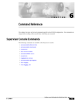
VIPER Technical Manual Detailed hardware description PC/104 16-bit I/O read/write access cycles AEN BALE SBHE A<0:15> VALID VALID IOCS16 IOCHRDY IOR/IOW DATA (read) VALID DATA (write) VALID VALID VALID PC/104 8-bit memory write access cycle AEN BALE SBHE A<0:23> VALID VALID MEMCS16 IOCHRDY (S)MEMW DATA (write) VALID VALID 8-bit memory read access cycles are not supported by the PXA255 PCMCIA controller for common memory space. © 2007 Eurotech Ltd Issue E 69 VIPER Technical Manual Detailed hardware description PC/104 16-bit memory read/write access cycles AEN BALE SBHE A<0:23> VALID VALID MEMCS16 IOCHRDY (S)MEMR/(S)MEMW DATA (read) DATA (write) VALID VALID VALID VALID Unsupported PC/104 interface features The PC/104 bus features not supported by the VIPER are as follows: • PC/104 IRQ9, IRQ14 and IRQ15 are not available under Windows CE as all interrupt sources are fully utilized. Therefore the PC104I2 register is not available. • DMA is not supported on the VIPER’s PC/104 interface. Therefore AEN is set to a constant logical zero. • Bus Mastering is not supported on the VIPER’s PC/104 interface. Therefore do not connect another VIPER or any other master add-on board to the VIPER PC/104 interface. • Shared interrupts are not supported on the VIPER’s PC/104 interface. Therefore do not connect more than one add-on board to the same interrupt signal line. • BALE is set to a constant logical one as the address is valid over the entire bus cycle. • The PXA255 PCMCIA memory controller does not support 8-bit memory read accesses for common memory space. © 2007 Eurotech Ltd Issue E 70 VIPER Technical Manual Detailed hardware description I2C The PXA255 I2C interface is brought out to the COMs connector PL4, see PL4 – COMS ports, page 89, for connection details. 73H 376H The I2C unit supports a fast mode operation of 400Kbits/s and a standard mode of 100Kbits/s. Fast-mode devices are downward-compatible and can communicate with standardmode devices in a 0 to 100Kbits/s I2C-bus system. As standard-mode devices, however, are not upward compatible, they should not be incorporated in a fast-mode I2C-bus system as they cannot follow the higher transfer rate and unpredictable states will occur. The I2C unit does not support the hardware general call, 10-bit addressing or CBUS compatibility. Keep bus loads below 200pF. TPM VL The VIPER provides the option for an Atmel AT97SC3201 Trusted Platform Module (TPM), which provides full TCG/TCPA V1.1b compatibility. For further details please contact Eurotech Ltd (see Appendix A – Contacting Eurotech, page 101) for purchasing information. 74H53 378H When the TPM is fitted OUT6 and OUT7 from the general purpose I/O interface are not available. © 2007 Eurotech Ltd Issue E 71 VIPER Technical Manual Detailed hardware description JTAG and debug access Debug access to the PXA255 processor is via the JTAG connector PL10. The Macraigor Wiggler and EPI MajicMX probe have been used to debug the PXA255 processor on the VIPER. There are many other debug tools that can be interfaced to the VIPER for access to the JTAG Interface of the PXA255 processor. 76H 7H The tables below detail the pins connections between the VIPER and Macraigor Wiggler or EPI MajicMX debug tools. Of the Wiggler and MajicMX debug tools the Wiggler provides the best low cost solution. 78H 79H 80H 81H 82H VIPER JTAG connections VIPER PL10 Debug tools pin names Pin Name Description MajicMX Wiggler 1 VCC3 3.3V Supply pin to JTAG debug tool VTRef, VSupply Vref, VTarget 3 GND Ground reference GND GND 4 nTRST PXA255 JTAG interface reset nTRST nTRST 6 TDI JTAG test data input to the PXA255 TDI TDI 7 TDO JTAG test data output from the PXA255 TDO TDO 8 TMS PXA255 JTAG test mode select TMS TMS 9 TCK PXA255 JTAG test clock TCK TCK 10 SRST System reset nSRST nSRST 2, 5 NC No Connect - - - - Not required on VIPER. RTCLK RTCK - - Not required on VIPER DBGREQ DBGRQ - - Not supported by VIPER DBGACK DBGACK In order to access the PXA255 your JTAG software needs to know the details of the CPLD on the VIPER. The latest version of the ispMACH 4128C 100 Pin TQFP BSDL file can be found on the Lattice Semiconductor web site. 83H © 2007 Eurotech Ltd Issue E 72 VIPER Technical Manual Power and power management Power and power management Power supplies The VIPER is designed to operate from a single +5V ±5% (4.75V to +5.25V) supply. The power connector PL16 has a +12V connection defined, but is not required for the VIPER under normal operation. It can be used to supply +12V to the PC/104 stack if required. For details of the power connector please see the section PL16 – Power connector, page 95. 379H 380H There are four onboard supply voltages derived from the +5V supply. These are +1.06 to +1.3V (microprocessor Core), +1.8V (CPLD Core) and two +3.3V. One +3.3V supply is dedicated for use with the CompactFLASH interface and +3.3V flat panels. The +5V supply is monitored automatically on-board; if this supply falls below +4V the board is reset. When the power supply rises above this threshold voltage the board comes out of reset and reboots itself. The power supply monitor ensures that the board does not hang if the supply voltage fails at any point. If a CompactFLASH and an LCD display are used, ensure the total current requirement on 3.3V does not exceed 900mA! Please check the datasheets of the devices you are using, as this supply is not protected! Battery backup An onboard Lithium-Ion non-rechargeable battery (CR2032) provides battery backup for the DS1338 RTC, SRAM and optional TPM security feature when there is no +5V supply to the board. An external battery (CR2032 or similar) may also be fitted. To use an external battery see PL16 – Power connector, page 95 for connections. 381H 382H The table below shows the typical and maximum current load on the external battery: Device load on battery Typical (µA) Maximum (µA) SRAM 0.2 2 DS1338 RTC with Clock Out Off / On 0.3 / 0.48 0.82/ 1.05 TPM (Optional) 2 4 Supply Supervisor 0.6 1 Total with RTC Clock Out Off 1.1 ( 3.1 with TPM) 3.82 (7.82 with TPM) Total with RTC Clock Out On 1.28 (3.28 with TPM) 4.05 (8.05 with TPM) An onboard Schottky diode drops 13mV from VBAT at 25°C. At -40°C this may increase to 170mV and at +85°C decrease below 10mV. The SRAM and DS1338 minimum voltages are 1.5V and 1.3V respectively. Reliable operation below these minimum voltages cannot be guaranteed. The VIPER does not provide a battery charging circuit. © 2007 Eurotech Ltd Issue E 73 VIPER Technical Manual Power and power management Power management All VIPER power-down features and alteration of PXA255 operating frequency are fully supported under Embedded Linux and VxWorks. Windows CE currently provides no power management support. To simplify the power consumption estimation of the VIPER, the following sections break down the process as follows: • Processor current estimations, page 75. 38H • 384H Power savings, page 77. 385H • 386H • External peripheral device power estimations, page 78. 387H 38H Power estimate examples, page 79. 389H 390H The sections immediately following these detail the VIPER features that can be shutdown. See pages 81 to 84. 391H 392H The section Processor current estimations, page 75, details current consumption of the VIPER for performance and power saving modes at different clock frequencies. Embedded Linux, Windows CE and VxWorks set up the PXA255 slightly differently: 39H 394H • Embedded Linux and VxWorks are booted from Redboot, which sets up the PXA255 clock frequency to 100MHz (CCCR=0x121). • Embedded Linux changes the Redboot setting to 400MHz in performance mode (CCCR=0x161). • VxWorks makes no changes to the Redboot setting. • Windows CE sets up the PXA255 clock frequency to 400MHz in power saving mode (CCCR=0x241). The section Power savings, page 77, only apples to Linux and VxWorks power estimation calculations, as Windows CE currently does not provide any power management support. This section shows potential power savings for that can be achieved by shutting down sections of the VIPER that are not required. 395H 396H The section External peripheral device power estimations, page 78, provides some examples of power consumption for various supported peripherals, such as LCD displays, CF and USB devices, which may or may not be used for your application. 397H 398H The section Power estimate examples, page 79, provides some examples to help you better understand how to use the information provided within the tables of the Processor current estimations, Power savings and External peripheral device power estimations sections. 39H 401H © 2007 Eurotech Ltd 402H 40H Issue E 403H 74 VIPER Technical Manual Power and power management Processor current estimations The current values in the tables below are referenced from running the VIPER at 400MHz in performance mode whilst the VIPER is idle. The positive values (not shown in brackets) are the current saving by running the VIPER at slower frequencies or in power saving mode. The negative values are the current increases that can be expected whilst the processor is near maximum activity load. The values shown in brackets show the total current of the VIPER from the 5V supply before taking into account any power savings from shutting down VIPER features or including additional current for external peripherals. Please refer to the relevant operating system Quickstart Manual to select an alternative operating frequency. Current saving from 5V when processor core is in performance mode Processor Vcore (V) 400MHz CCCR=0x161 266MHz 200MHz CCCR=0x143 CCCR=0x141 133MHz CCCR=0x123 Asleep Active 1.29 -106mA ±20mA - - - - Active 1.1 - -47mA ±20mA - - - Active 1.06 - - Idle 1.29 Idle 1.1 - 7mA (327mA) Idle 1.06 - - Asleep 0 - - © 2007 Eurotech Ltd Issue E 0mA (334mA) [Linux default] - -47mA ±20mA -36mA ±20mA - - - - 7mA (327mA) 12mA (322mA) - - 54mA (271mA) 75 VIPER Technical Manual Power and power management Current saving from 5V when processor core is in power saving mode Processor Vcore (V) 400MHz CCCR=0x241 300MHz CCCR=0x321 200MHz CCCR=0x221 100MHz CCCR=0x121 Asleep Active 1.29 -99mA ±20mA - - - - Active 1.1 - -46mA ±20mA - - - Active 1.06 - - Idle 1.29 9mA (325mA) [Win CE default] - - - - Idle 1.1 - 19mA (316mA) - - - Idle 1.06 - - Asleep 0 - - -32mA ±20mA -25mA ±20mA 29mA (308mA) [Redboot / 19mA (315mA) VxWorks default] - - - 54mA (271mA) Current figures when the microprocessor is active were taken with the following load conditions: calculating checksums of two files (first file: 1.1MB and second file: 0.5MB), and copying two 256kB files. When the microprocessor is asleep the PC/104 and AC97’ Codec clocks are shutdown. © 2007 Eurotech Ltd Issue E 76 VIPER Technical Manual Power and power management Power savings Use the table below to estimate power savings that can be achieved by shutting down features of the VIPER, or putting the VIPER to sleep. Power saving mode CPU Ethernet USB Audio VL VL Performance mode Serial Current saving ±3mA Total current ±3mA Total power ±15mW Current saving ±3mA Total current ±3mA Total power ±15mW - - - - - 0mA 325mA 1625mW 0mA 334mA 1670mW - - - - Sleep 25mA 300mA 1500mW 25mA 309mA 1545mW - - - Sleep - 38mA 287mA 1435mW 38mA 296mA 1480mW - - - Sleep Sleep 64mA 261mA 1305mW 64mA 270mA 1350mW - - Sleep - - 37mA 288mA 1440mW 37mA 297mA 1485mW - - Sleep - Sleep 62mA 263mA 1315mW 62mA 272mA 1360mW - - Sleep Sleep - 77mA 248mA 1240mW 77mA 257mA 1285mW - - Sleep Sleep Sleep 100mA 225mA 1125mW 100mA 234mA 1170mW - Sleep - - - 108mA 217mA 1085mW 108mA 226mA 1130mW - Sleep - - Sleep 131mA 194mA 970mW 131mA 203mA 1015mW - Sleep - Sleep - 146mA 179mA 895mW 146mA 188mA 940mW - Sleep - Sleep Sleep 172mA 155mA 775mW 172mA 162mA 810mW - Sleep Sleep - - 143mA 182mA 910mW 143mA 191mA 955mW - Sleep Sleep - Sleep 167mA 158mA 790mW 167mA 167mA 835mW - Sleep Sleep Sleep - 181mA 144mA 720mW 181mA 153mA 765mW - Sleep Sleep Sleep Sleep 205mA 120mA 600mW 205mA 129mA 645mW Sleep Sleep Sleep Sleep Sleep 276mA 49mA 245mW 285mA 49mA 245mW © 2007 Eurotech Ltd Issue E 77 VIPER Technical Manual Power and power management External peripheral device power estimations Take into account any external peripherals for your application, such as: • USB devices: keyboard, memory stick and mouse. • CompactFLASH socket: CompactFLASH memory or Microdrive. • Flat panel display: TFT logic + backlight, STN logic + backlight + bias voltage. The table below gives examples of addition current/power from external peripheral devices: Device Part number 32MB Sandisk CompactFLASH SDCFB-32-101-80 64MB FlashDio™ FDU100A USB memory stick NEC 5.5” LCD + Inverter (as used with VIPER-ICE) NL3224BC35-20 + 65PW31 Additional current Additional power Inserted, (no access) 1mA 5mW Reading constantly 48mA 240mW Inserted, (no access) 75mA 375mW Reading constantly 121mA 605mW LCD and backlight on 650mA 3250mW LCD on and backlight off 291mA 1455mW Condition For devices using the 3.3V supply from the CompactFLASH socket and FPD logic supply, use 92% as the regulator efficiency. © 2007 Eurotech Ltd Issue E 78 VIPER Technical Manual Power and power management Power estimate examples Example 1: VIPER [Linux] asleep (microprocessor in sleep mode and every power saving option enabled) In this case, the power consumed by the respective categories is: • VIPER current (Linux default) = 334mA ±3mA. • Power saving = 285mA (all power saving options enabled). • External peripheral current = 0mA. Therefore, the estimated VIPER current is: 334mA ±3mA - 285mA + 0mA = 49mA ±3mA (245mW ±15mW). Example 2: VIPER [Linux] at 200MHz in performance mode + LCD with backlight on In this case, the power consumed by the respective categories is: • VIPER current while idle = 334mA ±3mA - 7mA = 327mA ±3mA. VIPER current while active = 334mA + 47mA ±20mA = 381mA ±20mA. • Power saving = 0mA. • External peripheral current = 650mA (LCD). Therefore, the estimated VIPER current while idle (min) is: 327mA ±3mA + 650mA = 977mA, ±3mA (4885mW, ±15mW). and the estimated VIPER current while active (max) is: 381mA ±20mA + 650mA = 1031mA, ±20mA (5155mW, ±100mW). © 2007 Eurotech Ltd Issue E 79 VIPER Technical Manual Power and power management Example 3: VIPER [Windows CE] at 400MHz in power saving mode + LCD with backlight on + 64MB FlashDio™ USB memory stick In this case, the power consumed by the respective categories is: • VIPER current (Windows CE default) while idle VIPER current (Windows CE default) while active ±20mA = 334mA ±3mA - 9mA = 325mA ±3mA. = 334mA + 99mA = 433mA ±20mA. • Power saving = 0mA. • External peripheral current (USB memory stick quiescent) External peripheral current (USB memory stick read) 121mA = 650mA (LCD) + 75mA = 725mA. = 650mA (LCD) + = 771mA Therefore, the estimated VIPER current while idle (min) is: 325mA ±3mA + 725mA = 1050mA, ±3mA (5250mW, ±15mW). and the estimated VIPER current while active and reading from USB memory stick (max) is: 433mA ±20mA + 771mA = 1204mA, ±20mA (6020mW, ±100mW) . © 2007 Eurotech Ltd Issue E 80 VIPER Technical Manual Power and power management Processor power management The power manager in the PXA255 offers the ability to disable the clocks to the different internal peripherals. By default, all clocks are enabled after reset. To reduce power consumption disable the clocks for any unused peripherals. The clock speed of the processor core, PXbus (the internal bus connecting the microprocessor core and the other blocks of the PXA255), LCD and SDRAM can also be changed to achieve a balance between performance and power consumption. For more details on the internal power manager please see the PXA255 Developer’s Manual on the Development Kit CD. To adjust the core voltage, write the values shown in the following table to the LTC1659 DAC. When changing the core voltage it is important to ensure that the internal CPU clock is set to the correct voltage range. The CPU core supply must be set to a defined range for a particular clock. Please refer to the LTC1659 datasheet, Clocks and Power Manager section in the PXA255 Applications Processors Developer's Manual and Power Consumption Specifications section in the PXA255 Processor Electrical, Mechanical and Thermal Specification on the Development Kit CD. DAC Data Hex value CPU core voltage Comment 0x000 1.65V Not recommended to set the VCORE above 1.3V as the power consumption will increase for no performance benefit. 0x325 1.29V Typical VCORE for peak voltage range at 400MHz operation. Maximum VCORE for medium voltage range at 200MHz operation. 0xDE5 1.1V Typical VCORE for high voltage range at 300MHz operation. 0xFFF 1.06V Typical VCORE for low voltage and medium voltage range, suitable for 100MHz to 200MHz operation. When the microprocessor is in sleep mode, the CPU core voltage is shutdown. When changing between CPU core voltages it is important to adjust the DAC Data in steps of no greater than 0x100 at a time. © 2007 Eurotech Ltd Issue E 81 VIPER Technical Manual Power and power management To communicate with the VCORE DAC, use the following pins to emulate the LTC1659 interface: GPIO LTC1659 DAC pin function GPIO6 Data GPIO11 Clock GPIO19 Chip Select Before putting the PXA255 into sleep mode, ensure the R_DIS bit in the ICR register is set to ‘1’. The PXA255 is not designed to interface to 8-bit peripherals, so only the least significant byte from the word contains the data. Interrupt configuration and reset register Byte lane Bit Most Significant Byte Least Significant Byte 15 14 13 12 11 10 9 8 7 6 5 4 3 2 Field - - - - - - - - - - - - CF_ RST R_DIS Reset X X X X X X X X 0 0 0 0 0 0 R/W - - - - - - - - Address R 1 0 AUTO_ CLR RETRIG 0 0 R/W 0x14100002 ICR bit functions Bit Name 0 RETRIG 1 AUTO_CLR 2 R_DIS 3 CF_RST 4-7 - © 2007 Eurotech Ltd Issue E Value Function 0 No interrupt retrigger (embedded Linux/VxWorks) 1 Interrupt retrigger (Windows CE) 0 No auto clear interrupt / Toggle GPIO1 on new interrupt (embedded Linux and VxWorks). 1 Auto clear interrupt / pulse low for 1.12µS on GPIO1 on new interrupt from a new interrupt source (Windows CE). 0 Board reset normal 1 Board reset disable (Set before entering CPU sleep) 0 CompactFlash reset controlled by board reset 1 Reset CompactFlash X No function 82 VIPER Technical Manual Power and power management UART power management VL COM4 and COM5 are generated from an external Exar XR16C2850 DUART. This device supports a sleep mode. By enabling this feature the DUART enters sleep mode when there are no interrupts pending. Please see the XR16C2850 datasheet on the Development Kit CD for information on enabling the sleep mode. GPIO12 on the PXA255 can be used to power down the RS232 transceivers on COM1, 2, 3 and 4. The following table shows the affect of GPIO12 on the RS232 transceivers: GPIO12 Operation status Transmitters Receivers 0 Normal operation Active Active 1 Shutdown High-Z High-Z Placing the XR16C2850 and the RS232 transceivers into low power mode can reduce the power consumption of the VIPER up to 25mA ±3mA (125mW ±15mW). CompactFLASH power management The power supply to the CompactFLASH interface is controlled via software, and supports hot swap card insertion and CompactFLASH power down states. GPIO82 on the PXA255 is used to control the power supply. Setting this line to logic ‘0’ switches off power to the CompactFLASH interface. Ethernet power management The network interface supports a power down mode, which shuts down the internal MAC and PHY blocks of the network controller. Placing the controller into low power mode can reduce the power consumption of the VIPER by up to108mA ±3mA (540mW ±15mW). To power down the PHY write ‘1’ to the power down bit in the MII PHY Register 0, Control Register. To power down the MAC write ‘1’ to the EPH PowerEN bit in the Bank 1, Configuration Register. See the LAN91C111 datasheet contained on the Development Kit CD for further details. USB power management VL The USB Host controller supports a USB suspend state. Placing the controller into the USB suspend state can reduce the power consumption of the VIPER by up to 37mA ±3mA (185mW ±15mW). To suspend the USB, the software must write to the relevant bits in the HcControl Register (81h). Please see the ISP1160 datasheet contained on the Development Kit CD. To wake the USB Host Controller from suspend, pulse GPIO13 high. © 2007 Eurotech Ltd Issue E 83 VIPER Technical Manual Power and power management Audio power management VL The audio interface supports the AC’97 low power modes. Shutting down the digital and analogue interfaces can reduce consumption by up to 38mA ±3mA (190mW ±15mW). To shut down the AC’97 Codec, the software must write to the relevant bits in the Powerdown Control / Status Register (26h). Please see the LM4549 datasheet contained on the Development Kit CD. TPM VL If the VIPER has the TPM option the VIPER consumes a further 3.5mA (17.5mW) while the TPM IC is idle, and 17mA (85mW) while the TPM IC is operating. This device cannot be shutdown. Wake up events When the PXA255 processor is placed into sleep mode, two sources can be used to wake the processor. Source GPIO USER_CONFIG1 GPIO7 RTC Alarm Internal See section 3.5 in the PXA255 Applications Processor Developers Manual, included in the Development Kit CD. © 2007 Eurotech Ltd Issue E 84 VIPER Technical Manual Connectors, LEDs and jumpers Connectors, LEDs and jumpers The following diagram shows the location of the connectors, LEDs and jumpers on the VIPER: PL6 PL4 JP1 PL2 PL1 PL16 PL8 PL11 & PL12 PL10 JP3 Flash Access LED PL17 PL9 JP2 PL7 PL5 PL3 The connectors on the following pages are shown in the same orientation as the picture above, unless otherwise stated. © 2007 Eurotech Ltd Issue E 85 VIPER Technical Manual Connectors, LEDs and jumpers Connectors There are 13 connectors on the VIPER for accessing external devices: Connector Function Connector details in section… PL1 10/100BaseTX Ethernet interface PL1 – 10/100BaseTX Ethernet connector, page 87 Ethernet controller status LEDs PL2 – Ethernet status LEDs connector, page 87 PL2 PL3 LCD panel interface PL4 Serial ports PL5 CompactFLASH type I/II VL PL6 Audio VL PL7 USB VL PL8 TPM Tamper Detect PL9 GPIO PL10 JTAG PL11 64-way PC/104 expansion VL 40H 405H 406H 407H PL3 – LCD connector, page 88 408H 409H PL4 – COMS ports, page 89 95H 410H PL5 – CompactFLASH connector, page 90 96H 41H PL6 – Audio connector, page 91 412H 413H PL7 – USB connector, page 91 41H 415H PL8 – TPM Tamper connector, page 92 97H 416H PL9 – GPIO connector, page 92 98H 417H PL10 – JTAG connector, page 93 418H 419H PL11 & PL12 – PC/104 connectors, page 94 420H 421H VL PL12 40-way PC/104 expansion PL11 & PL12 – PC/104 connectors, page 94 42H 423H VL PL16 Power / battery / external reset PL16 – Power connector, page 95 PL17 USB client JP1 RS485/422 configuration jumpers 42H JP2 LCD voltage select jumper JP3 User configuration and reset jumper JP4 © 2007 Eurotech Ltd Battery jumper Issue E 425H PL17 – USB client connector, page 95 426H 427H JP1 – RS485/422 configuration jumpers, page 96 428H 429H JP2 – LCD voltage select jumper, page 96 430H 431H JP3 – User configuration and reset jumper, page 96 432H 43H JP4 – Battery jumper, page 96 43H 435H 86 VIPER Technical Manual Connectors, LEDs and jumpers PL1 – 10/100BaseTX Ethernet connector Connector: Oupiin 2015-2X4GD/SN, 8-way, 2.54mm (0.1”) x 2.54mm (0.1”) dual row header Mating connector: FCI 71600-008LF Pin Signal name Pin Signal name 1 TX+ 2 TX- 3 RX+ 4 NC 5 NC 6 RX- 7 NC 8 LANGND PL2 – Ethernet status LEDs connector Connector: Neltron 2417SJ-06-PHD, 6-way, 2mm (0.079”) x 2mm (0.079”) pin housing Mating connector: Neltron 2418HJ-06-PHD Mating connector crimps (x4): Neltron 2418TJ-PHD Pin Signal name Pin Signal name 1 3.3V 2 Link 3 3.3V 4 Activity 5 NC 6 NC © 2007 Eurotech Ltd Issue E 5 1 6 2 87 VIPER Technical Manual Connectors, LEDs and jumpers PL3 – LCD connector Connector: Oupiin 3214-40C00RBA/SN, 40-way, 1.27mm (0.05”) x 2.54mm (0.1”) right angled boxed header Mating connector: Oupiin 1203-40GB/SN Pin Signal name Pin Signal name 1 BLKEN# 2 BLKSAFE 3 GND 4 GND 5 NEGBIAS 6 LCDSAFE 7 GPIO16/PWM0 8 POSBIAS 9 GND 10 GND 11 FPD0 12 FPD1 13 FPD2 14 FPD3 15 GND 16 GND 17 FPD4 18 FPD5 19 FPD6 20 FPD7 21 GND 22 GND 23 FPD8 24 FPD9 25 FPD10 26 FPD11 27 GND 28 GND 29 FPD12 30 FPD13 31 FPD14 32 FPD15 33 GND 34 GND 35 FCLK / VSYNC 36 BIAS / DE 37 GND 38 GND 39 PCLK / CLOCK 40 LCLK / HSYNC © 2007 Eurotech Ltd Issue E As viewed from the connector pins 88 VIPER Technical Manual Connectors, LEDs and jumpers PL4 – COMS ports Connector: Oupiin 3012-40GRB/SN, 40-way, 2.54mm (0.1”) x 2.54mm (0.1”) dual row IDC boxed header Mating connector: FCI 71600-040LF Pin 1 VL VL Signal name 2 SCL (I C) 2 Pin Signal name 2 SDA (I2C) 2 3 GND (I C) 4 3.3V (I C) 5 TX5+ (RS422) (TX5+/RX5+ RS485) 6 TX5- (RS422) (TX5-/RX5- RS485) 7 RX5+ (RS422) 8 RX5- (RS422) 9 GND 10 GND 11 TX3 12 RX3 13 RX2 14 RTS2 15 TX2 16 CTS2 17 GND 18 GND 19 GND 20 NC 21 DCD4 22 DSR4 23 RX4 24 RTS4 25 TX4 26 CTS4 27 DTR4 28 RI4 29 GND 30 NC 31 DCD1 32 DSR1 33 RX1 34 RTS1 35 TX1 36 CTS1 37 DTR1 38 RI1 39 GND 40 NC I 2C COM5 COM3 COM2 COM4 COM1 As viewed from the connector pins © 2007 Eurotech Ltd Issue E 89 VIPER Technical Manual Connectors, LEDs and jumpers PL5 – CompactFLASH connector Connector: 3M N7E50-N516RB-50, 50-way CompactFLASH Type II connector Pin Signal name Pin Signal name 26 /CD1 1 GND 27 D11 2 D03 28 D12 3 D04 29 D13 4 D05 30 D14 5 D06 31 D15 6 D07 32 /CE2 7 /CE1 33 /VS1 (GND) 8 A10 34 /IORD 9 /OE 35 /IOWR 10 A09 36 /WE 11 A08 37 RDY/BSY 12 A07 38 +3.3V 13 +3.3V 39 CSEL (GND) 14 A06 40 N/C 15 A05 41 /RESET 16 A04 42 WAIT 17 A03 43 /INPACK (NU) 18 A02 44 /REG 19 A01 45 N/C 20 A00 46 N/C 21 D00 47 D08 22 D01 48 D09 23 D02 49 D10 24 /IOCS16 50 GND 25 /CD2 © 2007 Eurotech Ltd Issue E 90 VIPER Technical Manual Connectors, LEDs and jumpers PL6 – Audio connector VL Connector: Oupiin 2015-2X6GDB/SN, 12-way, 2.54mm (0.1”) x 2.54mm (0.1”) dual row header Mating connector: FCI 71600-014LF (with pins 13 and 14 blanked off) Pin Signal name Pin Signal name 1 LEFT IN 2 LEFT OUT 3 GND 4 GND 5 RIGHT IN 6 RIGHT OUT 7 GND 8 AMP LEFT OUT 9 MIC VREF OUT 10 MIC IN 11 AMP RIGHT OUT 12 GND PL7 – USB connector VL Connector: Oupiin 2011-2x5GSB/SN, 10-way, 2.54mm (0.1”) x 2.54mm (0.1”) dual row header Mating connector: FCI 71600-010LF Pin Signal name Pin Signal name 1 VBUS-1 2 VBUS-2 3 DNEG-1 4 DNEG-2 5 DPOS-1 6 DPOS-2 7 GND 8 GND 9 SHIELD 10 SHIELD © 2007 Eurotech Ltd Issue E 91 VIPER Technical Manual Connectors, LEDs and jumpers PL8 – TPM Tamper detect connector (optional) VL Connector: JST B2B-ZR(LF)(SN), 2-way, single row, 1.5 mm (0.06”) Shrouded Header Mating housing: JST ZHR-2 Mating housing crimps: JST SZH-002T-P0.5 Pin Signal name Pin Signal name 1 VCC_BACKUP 2 TPM_TAMPER_DETECT 2 1 PL9 – GPIO connector Connector: Oupiin 2115-2X10GDN/SN, 20-way, 2mm (0.079”) x 2mm (0.079”) dual row header Mating connector: FCI 69307-020LF Mating connector crimps (x20): FCI 77138-001LF Pin Signal name Pin Signal name 1 +5V 2 +5V 3 IN0 4 IN1 5 IN2 6 IN3 7 IN4 8 IN5 9 IN6 10 IN7 11 OUT0 12 GND 13 OUT0_ INVERTED 14 OUT1 15 OUT2 16 OUT3 17 OUT4 18 OUT5 19 OUT6 20 OUT7 © 2007 Eurotech Ltd Issue E 92 VIPER Technical Manual Connectors, LEDs and jumpers PL10 – JTAG connector Connector: Oupiin 2011-2x5GSB/SN, 10-way, 2.54mm (0.1”) x 2.54mm (0.1”) dual row header Mating connector: FCI 71600-010LF Pin Signal name Pin Signal name 1 VCC3 2 NC 3 GND 4 nTRST 5 NC 6 TDI 7 TDO 8 TMS 9 TCLK 10 SRST © 2007 Eurotech Ltd Issue E 93 VIPER Technical Manual Connectors, LEDs and jumpers PL11 & PL12 – PC/104 connectors VL Connectors: • Astron 25-1201-232-2G-R, 64-way, 2.54mm (0.1”) x 2.54mm (0.1”) Stackthrough PC/104 compatible connector (row A & B) • Astron 25-1201-220-2G-R, 40-way, 2.54mm (0.1”) x 2.54mm (0.1”) Stackthrough PC/104 compatible connector (row C & D) PL12 Pin Row D 0 1 2 3 4 5 6 7 8 9 10 11 12 13 14 15 16 17 18 19 © 2007 Eurotech Ltd GND /MEMCS16 /IOCS16 IRQ10 IRQ11 IRQ12 IRQ15 IRQ14 NU (DACK0) NU (DRQ0) NU (DACK5) NU (DRQ5) NU (DACK6) NU (DRQ6) NU (DACK7) NU (DRQ7) +5V NC (Master) GND GND Issue E Row C GND /SBHE LA23 LA22 LA21 LA20 LA19 LA18 LA17 /MEMR /MEMW D8 D9 D10 D11 D12 D13 D14 D15 KEY PL11 Pin Row A Row B 1 2 3 4 5 6 7 8 9 10 11 12 13 14 15 16 17 18 19 20 21 22 23 24 25 26 27 28 29 30 31 32 GND RSTDRV +5V IRQ9 NC NU (DRQ2) NC NC +12V KEY /SMEMW /SMEMR /IOW /IOR NU (DACK3) NU (DRQ3) NU (DACK1) NU (DRQ1) NU (REFSH) 8MHz Clk IRQ7 IRQ6 IRQ5 IRQ4 IRQ3 NU (DACK2) NU (TC) BALE +5V OSC GND GND /IOCHCK D7 D6 D5 D4 D3 D2 D1 D0 IOCHRDY AEN A19 A18 A17 A16 A15 A14 A13 A12 A11 A10 A9 A8 A7 A6 A5 A4 A3 A2 A1 A0 GND 94 VIPER Technical Manual Connectors, LEDs and jumpers PL16 – Power connector Connector: Molex 22-05-7058, 5-way, 2.54mm (0.1") Pitch KK® Header - Right Angle Friction Lock 7395 series connector Mating connector: Molex 22-01-2055, 5-way, 2.54mm (0.1") Pitch KK® Crimp Terminal Housing 2695 series connector Pin Signal name 1 +5V 2 GND 3 VBAT 4 +12V 5 /Reset VBAT provides the facility to fit an external battery in conjunction with the onboard battery (1.5V to 3.3V input range) for the backup supply of the 256KB static RAM, Dallas DS1338 56 x 8 serial real time clock and optional TPM security tamper. +12V connection defined, but is not required for the VIPER under normal operation. It can be used to supply +12V to the PC/104 stack if required. A momentary switch (push to make) may be connected across /Reset and GND. Do not connect the switch across /Reset and +5V or +12V. PL17 – USB client connector Connector: Neltron 2417SJ-03-F4, 3-way, 2mm Pitch Mating connector: Toby PH200-03H, PH200 Series 2mm housings & crimps Pin Signal name 1 USBC- 2 USBC+ 3 GND © 2007 Eurotech Ltd Issue E 95 VIPER Technical Manual Connectors, LEDs and jumpers JP1 – RS485/422 configuration jumpers VL Connector: Oupiin 2011-2x5GSB/SN, 10-way, 2.54mm (0.1”) x 2.54mm (0.1”) dual row through-hole unshrouded header Ref JP1 Pin Signal name Pin Signal name 1 PL4_RX5- 2 PL4_RX5+ 3 RX5- 4 RX5+ 5 PL4_RX5/TX5- 6 PL4_RX5/TX5+ 7 PL4_RX5+ 8 RX5-_120R 9 PL4_RX5/TX5+ 10 RX5/TX5-_120R 1 2 9 10 JP2 – LCD voltage select jumper Connector: Oupiin 2011-1x3GSB/SN, 3-way, 2.54mm (0.1”) single row through-hole header Ref JP2 Pin Signal name 1 5V 2 LCD Logic Supply 3 3.3V 1 3 JP3 – User configuration and reset jumper Connector: Oupiin 2011-2x3GSB/SN, 6-way, 2.54mm (0.1”) x 2.54mm (0.1”) dual row through-hole unshrouded header Ref JP3 Pin Signal name Pin Signal name 1 GND 2 USER_CONFIG1 3 GND 4 Reserved 5 GND 6 RESETSW 1 2 5 6 JP4 – Battery jumper Connector: Oupiin 2011-1x2GSB/SN, 2-way, 2.54mm (0.1”) single row through-hole header Ref JP4 © 2007 Eurotech Ltd Pin Signal name Pin Signal name 1 Battery Backup Switch Input 2 Battery + Terminal Issue E 1 2 5 6 96 VIPER Technical Manual Connectors, LEDs and jumpers Status LEDs There is a single status LED on the VIPER, which indicates FLASH access to the bootloader FLASH or the main FLASH memory/silicon disk. © 2007 Eurotech Ltd Issue E 97 VIPER Technical Manual Connectors, LEDs and jumpers Jumpers There are seven user selectable jumpers on the VIPER. Their use is explained below. Default settings The default positions of the jumpers are shown below. Jumper functions described in silkscreen on the board are shown in blue. JP1 JP2 VL LK7 LK6 JP3 JP4 LK8 4 3 5 6 5 7 8 LK5 9 10 LK4 1 2 LK3 3 4 LK2 5 6 LK1 1 2 LK9 BAT Connect FD FD 1-2 3-4 5-6 USR RSVD RST 3 LCD Voltage 1 +3.3V 2 +5V 1 HD HD 120R 120R Reset – LK1 on JP3 A momentary switch (push to make) may be connected to LK1. When pressed the board goes into a full hardware reset. When the switch is released (open circuit) the board reboots. Reserved – LK2 on JP3 This jumper is reserved for factory use only. Please do not fit LK2 across JP3 pins 3 and 4. User configurable jumper 1 – LK3 on JP3 This jumper can be used by an application program to signify a configuration setting. LK3 Description GPIO7 read as ‘0’. Default setting: GPIO7 read as ‘1’. The USER_CONFIG1 (GPIO7) signal on LK3 may be used to wake the VIPER from sleep. One way of doing this is to connect a momentary push to make switch to LK3. © 2007 Eurotech Ltd Issue E 98 VIPER Technical Manual Connectors, LEDs and jumpers RS485/422 configuration – LK4, LK5, LK6 and LK7 on JP1 VL These jumpers are used to enable/disable the RS485 receive buffer and RS485/422 line termination. See COM5 – RS422/485 interface, page 65, for more details. 436H LK4 437H Description (RS485 TX/RX) RS422 TX line termination resistor (120Ω) connected. Default setting: (RS485 TX/RX) RS422 TX line termination resistor (120Ω) disconnected. LK5 Description RS422 RX line termination resistor (120Ω) connected. Default setting: RS422 RX line termination resistor (120Ω) disconnected. LK6 & LK7 Description RS422 full-duplex. Default setting: RS485 half-duplex. Only fit LK4 and LK5 if the VIPER is at the end of the network. © 2007 Eurotech Ltd Issue E 99 VIPER Technical Manual Connectors, LEDs and jumpers LCD supply voltage – LK8 on JP2 This jumper selects the supply voltage for the LCD logic supply. LK8 Description Supply LCD logic with 5V. Default setting: Supply LCD logic with 3.3V. If the LCD requires a 5V supply, please refer to the LCD datasheet to ensure that the display is compatible with 3.3V logic. Battery jumper – LK9 on JP4 This jumper connects the battery to the battery back-up circuit. LK9 Description Battery is connected to the board circuit. Default setting: Battery is disconnected from board circuit The battery is disconnected when board is shipped. If battery back up is required, jumper LK9 must be fitted to JP4 before installation of the VIPER. © 2007 Eurotech Ltd Issue E 100 VIPER Technical Manual Appendix A – Contacting Eurotech Appendix A – Contacting Eurotech Eurotech sales Eurotech’s sales team is always available to assist you in choosing the board that best meets your requirements. Eurotech Ltd 3 Clifton Court Cambridge CB1 7BN UK Tel: Fax: Email: +44 (0)1223 403410 +44 (0)1223 410457 [email protected] 9H Comprehensive information about our products is also available at our web site: www.eurotech-ltd.co.uk. 10H While Eurotech’s sales team can assist you in making your decision, the final choice of boards or systems is solely and wholly the responsibility of the buyer. Eurotech’s entire liability in respect of the boards or systems is as set out in Eurotech’s standard terms and conditions of sale. If you intend to write your own low level software, you can start with the source code on the disk supplied. This is example code only to illustrate use on Eurotech’s products. It has not been commercially tested. No warranty is made in respect of this code and Eurotech shall incur no liability whatsoever or howsoever arising from any use made of the code. Eurotech technical support Eurotech has a team of dedicated technical support engineers available to provide a quick response to your technical queries. Tel: Fax: Email: +44 (0)1223 412428 +44 (0)1223 410457 [email protected] 10H Eurotech Group Eurotech Ltd is a subsidiary of Eurotech Group. For further details see www.eurotech.com 102H © 2007 Eurotech Ltd Issue E 101 VIPER Technical Manual Appendix B – Specification Appendix B – Specification Microprocessor 400MHz (VIPER) or 200MHz (VIPER-Lite) PXA255 processor. Memory 16MB, 64MB 3.3V un-buffered SDRAM. 16MB, 32MB Intel StrataFLASH. 1MB Bootloader ROM. 256k SRAM (battery backed). VL Graphics controller PXA255 Flat panel controller offering resolutions: • 320 x 240, 8/16 bpp. • 640 x 480, 8/16 bpp. • 800 x 600, 8 bpp (not recommended by Eurotech Ltd). Peripherals Serial: VL RS232 on COM1, COM2, COM3, & COM4 RS422/485 on COM5. VL CompactFLASH: One Type I/II CompactFLASH socket. VL Audio: 16-bit AC’97-compliant CODEC, stereo. 20Hz to 20kHz In / Out frequency response VL VL Temperature USB Host: Dual channel v1.1 host support USB Client One channel v1.1 client support Network: One 10/100BaseTX NIC port TPM (Optional): TCG/TCPA V1.1b Compatibility 1024-bit RSA signature in 100 ms. Operating: -20oC (-4oF) to +70oC (+158oF) (commercial). -40oC (-40oF) to +85oC (+185oF) (industrial). Humidity 10% to 90% RH (non-condensing). Real time clock Accuracy +/- 1 minute/month. Software RedBoot Bootloader for embedded Linux or VxWorks. Eboot Bootloader for Windows CE. Power requirement 5V +/- 5%. 2W typical consumption (no LCD, CF or USB devices fitted). 49mA (245mW) in sleep mode. Battery input 1.5v to 3.3v, typical discharge 2μA. Dimensions PC/104 compatible format: 3.775” x 3.550”, 96mm x 91mm. Weight 99 grams. © 2007 Eurotech Ltd Issue E 102 VIPER Technical Manual Appendix C – Mechanical diagram Appendix C – Mechanical diagram Unit of measure = mm (1inch = 25.4mm) 88.61 29.55 8.89 12.70 15.24 0.00 5.57 4.44 95.89 PL2 90.80 A 93.47 PL8 93.22 82.55 82.93 1.78 Chassis ground mounting positions A Ø3.18 FOUR (A) HOLES PL1 82.55 PL5 PL4 PL3 56.36 53.34 JP1 53.09 JP2 PL7 JP3 41.72 39.95 32.84 JP4 PL9 PL10 20.65 PL17 25.40 21.75 PL6 16.54 12.70 16.39 PL11 7.62 5.44 5.08 A PL12 A 87.34 85.09 0.00 87.06 77.83 72.53 58.17 44.41 38.16 29.21 14.73 12.70 6.35 10.51 5.08 8.26 0.00 PL16 90.17 0.00 NOTES 1) ALL CONNECTOR DIMENSIONS ARE TAKEN FROM PIN 1 When mounting the VIPER use only M3 (metric) or 4-40 (imperial) screws. The mounting pad is 6.35mm, 0.25” and the hole is 3.175mm, 0.125”, so ensure any washers fitted are smaller than the pad. Using oversized screws and washers, or tooth locking washers, can cause short circuits and over-voltage conditions. We recommend that you use a Loctite screw thread lock or a similar product over tooth locking washers. © 2007 Eurotech Ltd Issue E 103 VIPER Technical Manual Appendix D – Reference information Appendix D – Reference information Product information Product notices, updated drivers, support material, 24hr-online ordering: www.eurotech-ltd.co.uk PC/104 Consortium PC/104 specifications, vendor information and available add on products: www.PC/104.org USB Information Universal Serial Bus (USB) specification and product information: www.usb.org CFA (CompactFlash Association) CF+ and CompactFlash specification and product information: www.compactflash.org TCG (Trusted Computing Group) TCG TPM specification: www.trustedcomputinggroup.org/home Intel Intel XScale™ PXA255 processor documentation: www.intel.com www.intel.com/design/pca/prodbref/252780.htm Standard Microsystems Corporation SMSC SMC91C111 Ethernet controller documentation: www.smsc.com Exar Corporation Exar XR16C2850 DUART with 128Byte FIFO documentation: www.exar.com © 2007 Eurotech Ltd Issue E 104 VIPER Technical Manual Appendix D – Reference information National Semiconductor Corporation National Semiconductor LM4549 AC’97 Codec documentation: www.national.com 12H Koninklijke Philips Electronics N.V. Philips ISP1160 USB host controller documentation: www.philips.com 13H Maxim Integrated Products Inc. Maxim DS1338 56 x 8 serial real time clock documentation: www.maxim-ic.com 14H Linear Technology Corporation Linear Technology LTC1659 Micropower DAC documentation: www.linear.com 15H © 2007 Eurotech Ltd Issue E 105 VIPER Technical Manual Appendix E – Acronyms and abbreviations Appendix E – Acronyms and abbreviations Amp ATA BTUART CAN CCCR CF CFI CODEC COM CPLD CPU CMOS CRT DAC DMA DUART EEPROM EMC EPROM EXT2 FFUART FIFO FLASH FPIF1 GPIO I2C ICE ICR IEEE IO ISA JTAG LED LCD LSB LVDS NA NC NU OS PC/104 PCB PROM PWM © 2007 Eurotech Ltd Issue E Amplifier Advanced Technology Attachment Bluetooth Universal Asynchronous Receiver / Transmitter Control Area Network Core Clock Configuration Register Compact Flash Common FLASH Interface Coder/Decoder Communication Port Complex Programmable Logic Device Central Processing Unit (PXA255) Complementary Metal Oxide Semiconductor Cathode Ray Tube Digital to Analogue Converter Direct Memory Access Dual Universal Asynchronous Receiver / Transmitter Electrically Erasable and Programmable Read-Only Memory Electromagnetic Compatibility Erasable and Programmable Read-Only Memory Linux's standard file system type Full Function Universal Asynchronous Receiver / Transmitter First-In First-Out A non-volatile memory that is preserved even if the power is lost Flat Panel Interface General Purpose Input/Output (=IIC) Intra Integrated Circuit bus In-Circuit-Emulator Interrupt Control and Reset register Institute of Electrical and Electronics Engineers Input/Output Industry Standard Architecture, Bus in the IBM-PC Joint Test Action Group of IEEE Light Emitting Diode Liquid Crystal Display Least Significant Bit Low Voltage Differential Signalling Not Applicable No Connect Not Used Operating System Offers full architecture, hardware and software compatibility with the PC ISA bus, but in ultra-compact 96mm x 91mm (3.775" x 3.550") stackable modules Printed Circuit Board Programmable Read-Only Memory Pulse-Width Modulation 106 VIPER Technical Manual RAM Reg RSA RTC RX SBC SDRAM SRAM STN STUART TCG/TCPA TPM TFT TX UART UPS USB VAC VDC VGA VIPER-ICE © 2007 Eurotech Ltd Issue E Appendix E – Acronyms and abbreviations Random Access Memory Regulator public key cryptosystem invented by Rivest, Shamir and Adleman Real Time Clock Receive Single Board Computer Synchronous Dynamic Random Access Memory Static Random Access Memory Super Twisted Nematic, technology of passive matrix liquid crystal Standard Universal Asynchronous Receiver / Transmitter Trusted Computing Group / Platform Alliance Trusted Platform Module Thin Film Transistor, a type of LCD flat-panel display screen Transmit Universal Asynchronous Receiver / Transmitter Uninterruptible Power Supply Universal Serial Bus Voltage Alternating Current Voltage Direct Current Video Graphics Adapter, display resolution 640 x 480 pixels VIPER-Industrial Compact Enclosure 107 VIPER Technical Manual Appendix F – RoHS-6 Compliance - Materials Declaration Form Appendix F – RoHS-6 Compliance - Materials Declaration Form Confirmation of Environmental Compatibility for Supplied Products Substance Maximum concentration Lead 0.1% by weight in homogeneous materials Mercury 0.1% by weight in homogeneous materials Hexavalent chromium 0.1% by weight in homogeneous materials Polybrominated biphenyls (PBBs) 0.1% by weight in homogeneous materials Polybrominated diphenyl ethers (PBDEs) 0.1% by weight in homogeneous materials Cadmium 0.01% by weight in homogeneous materials The products covered by this certificate include: Product Name Eurotech Ltd Part Number VIPER VIPER-M64-F32-V2-R6 VIPER VIPER-M64-F16-V2-R6 VIPER VIPER-M64-F32-V2-I-R6 VIPER VIPER-M64-F16-V2-I-R6 VIPER-Lite VIPERL-M64-F32-R6 VIPER-Lite VIPERL-M64-F16-R6 Eurotech Ltd has based its material content knowledge on a combination of information provided by third parties and auditing our suppliers and sub-contractor’s operational activities and arrangements. This information is archived within the associated Technical Construction File. Eurotech Ltd has taken reasonable steps to provide representative and accurate information, though may not have conducted destructive testing or chemical analysis on incoming components and materials. Additionally, packaging used by Eurotech Ltd for its products complies with the EU Directive 2004/12/EC in that the total concentration of the heavy metals cadmium, hexavalent chromium, lead and mercury do not exceed 100 ppm. © 2007 Eurotech Ltd Issue E 108 VIPER Technical Manual Index Index A active display signal · 36 address map · 19 amplifier · 5, 7, 16, 56 anti-static · 12 assignments, GPIO pins · 22 audio · 5, 7, 16, 56 connector · 91 power management · 84 B backlight · 7 brightness · 37 enable · 37 inverter connector · 42 base TX ethernet · 62 battery · 73 battery input · 5, 6 block diagram · 18 board · 4 custom configurations · 4 bootloader · 7, 16 breakout board · 62 bus, expansion · 17 C cache · 7 clock · 8, 21, 26, 102 CODEC · 7 COM · 5 ports connector · 89 COM1 · 64 COM2 · 64 COM3 · 64 COM4 · 65 COM5 · 65, 99 CompactFLASH · 5, 6, 7, 15, 28 connector · 90 power · 83 connector · 85, 86 audio · 91 CompactFLASH · 90 COMS port · 89 ethernet · 87 ethernet status · 87 JTAG · 93 LCD · 88 © 2007 Eurotech Ltd Issue E PC/104 · 94 power · 95 USB · 91 contact details · 101 controller, graphics · 102 custom configurations · 4 D dark boot · 98 development kits · 10, 11 digital I/O · 5, 6 dimensions · 102 display · 34 E EMC · 12 EPROM · 7 ethernet · 5, 6, 8, 16, 62 breakout board · 62 connector · 87 LED · 5, 6 power management · 83 expansion bus · 17 external device power · 78 external interrupt · 30 F features · 7 FIFO · 7 flash access LED · 85 FLASH memory · 27 flat panel · 34 FPIF · 38, 43, 48, 53 G general purpose I/O · 57 GPIO · 8 pins assignments · 22 GPIO connector · 92 graphics controller · 102 H heat sink · 21 humidity · 102 109 VIPER Technical Manual Index I P I/O · 5, 6 Intel PXA255 · 4 interface, USB · 60 internal interrupt · 30 interrupt · 30 external · 30 internal · 30 passive display signal · 36 PC/104 · 30, 67 consortium · 104 interface · 5 PC/104 interrupts Linux · 32 Windows CE · 33 peripheral · 102 peripheral control module · 21 PL1 · 85, 86, 87 PL10 · 85, 86, 93 PL11 · 85, 86, 94 PL12 · 85, 86, 94 PL13 · 86 PL16 · 85, 86, 95 PL17 · 85, 86, 96 PL2 · 85, 86, 87 PL3 · 85, 86, 88 PL4 · 85, 86, 89 PL5 · 85, 86, 90 PL6 · 85, 86, 91 PL7 · 85, 86, 91 PL8 · 85, 86, 92 PL9 · 85, 86, 92 port serial · 7, 64 USB · 7 power · 5, 6, 8, 73, 102 audio · 84 CompactFLASH · 83 connector · 73, 95 ethernet · 83 external device · 78 management · 74 processor · 75, 81 supply · 73 UART · 83 USB · 83 voltage · 73 processor · 4, 5, 6, 7, 102 power · 75 power management · 81 PXA255 · 21 product information · 104 PXA255 · 21 J JTAG · 5, 6, 8 connector · 93 jumper · 5, 6, 8, 13, 85, 98 header · 96 L LAN · 16 LCD · 34, 38, 48, 53 backlight brightness · 37 backlight enable · 37 connector · 88 generic connector · 40, 46, 51 logic supply enable · 37 SBC cable connector · 39, 45, 50, 54 LED · 5, 6, 85, 97 Linux · 15, 16, 21, 27, 29, 31, 32, 82, 102 PC/104 interrupts · 32 LK1 · 85, 86, 96, 98 LK2 · 98 LK3 · 98 LK4 · 99, 100 LK5 · 99, 100 LK6 · 99, 100 LK7 · 99, 100 M map, address · 19 mechanical diagram · 103 memory · 7, 27, 102 microphone · 5, 7, 16, 56 microprocessor · 102 MMU · 20 N R network · 8 O on board device power · 77 operating frequency · 21 © 2007 Eurotech Ltd Issue E RAM, static · 28 real time clock · 8, 26, 102 RedBoot · 102 reset · 98 resolution · 7 RoHS compliance · 12 110 VIPER Technical Manual RS232 · 7, 15, 64, 65 RS422 · 7, 15, 65, 99, 100 RS485 · 7, 15, 65, 99, 100 RTC · 8, 26 S SDRAM · 27 serial port · 5, 6, 7, 15, 64 silicon disk · 7, 27 software · 102 source code · 101 specification · 102 SRAM · 7 static · 12 static RAM · 28 status LED · 97 STN · 5, 6, 36, 38, 48, 53 bias connector · 42 StrataFLASH · 5, 6, 7, 27 support products · 9 support, technical · 101 system control module · 21 memory · 7 T technical support · 101 temperature · 102 TFT · 5, 6, 7, 9, 35, 38, 43, 48 timer, watchdog · 26 TPM · 71, 84 TPM Tamper detect connector · 92 trusted platform module · 71, 84 © 2007 Eurotech Ltd Issue E Index U UART · 7 power management · 83 USB · 5, 6, 7, 16, 104 connector · 91 interface · 60 power management · 83 V video · 7 VIPER · 4 custom configurations · 4 development kits · 11 features · 7 support products · 9 using · 15 VIPER-ICE development kits · 10 VIPER-Lite · 4 custom configurations · 4 development kits · 11 features · 7 features not available · 4, 13, 18 support products · 9 using · 15 VxWorks · 15, 16, 21, 27, 102 W wake up events · 84 watchdog · 8 timer · 26 weight · 102 Windows CE · 15, 16, 21, 27, 102 PC/104 · 33 111