1
Chapter 2
ASA 5505
Product Overview
Product Overview
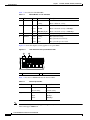
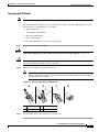
This section describes the front and rear panels. Figure 2-1 shows the front panel LEDs.
Figure 2-1
Front Panel LEDs and Ports
3
4
LINK/ACT
5
Power
6
Status
7
Active
8
VPN
SSC
100 MBPS
1
2
3
4
5
6
7
Cisco ASA 5505 Series
Adaptive Security Appliance
1
153644
0
0
2
1
USB 2.0 interface
5
Status
2
100 Mbps
6
Active
3
LINK/ACT LEDs
7
VPN
4
Power
8
SSC
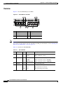
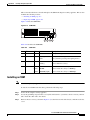
Figure 2-2 shows the rear panel LEDs and Ports.
Figure 2-2
Rear Panel LEDs and Ports (AC Power Supply Model Shown)
3
2
5
Cisco ASA SSC-05
Security
Services
Card Slot
Status
console
8
POWER
48VDC
RESET
2
7 POWER over ETHERNET 6
5
4
1
3
2
1
0
6
4
1 Power 48VDC
5
Console port
2 SSC slot
6
USB 2.0 interface
7
Reset button
8
Lock slot
3 Network interface LEDs
4 Network interfaces
1
153645
1
7
1. Ports 6 and 7 are PoE ports, used for devices that can be powered by the network interface, IP phones for example. They
can also be used as regular Ethernet switch ports, just like the ports numbered 0 through 5.
Cisco ASA 5500 Series Hardware Installation Guide
2-2
OL-10089-01