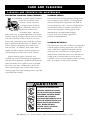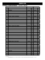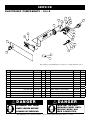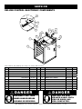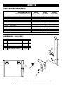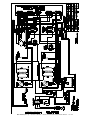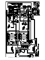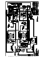
1
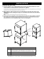
Holding Cabinet Deluxe or Simple Control Models: 300-s 5 00-s 750-s 1000-s 1200-s 1000-UP 1200-UP 1200-UP 1000-UP 1200-s 1000-s • 750-s Installation • Operation • Maintenance 500-s 300-s W164 N9221 Water Street • P.O. Box 450 • Menomonee Falls, Wisconsin 53052-0450 USA PHONE: 262.251.3800 • 800.558.8744 USA / CANADA FAX: 262.251.7067 • 800.329.8744 U . S . A . www.alto-shaam.com printed in u.s.a. ONLY MN-29423 (Rev. 2) • 11/14 Delivery . . . . . . . . . . . . . . . . . . . . . . . . . . . . . . . . . . . 1 Unpacking. . . . . . . . . . . . . . . . . . . . . . . . . . . . . . . . . . 1 Safety Procedures and Precautions. . . . . . . . . . . . . . . 2 Sanitation Sanitation/Food Safety. . . . . . . . . . . . . . . . . . . . . 23 Internal Food Product Temperatures. . . . . . . . . . . 23 Installation Installation Requirements. . . . . . . . . . . . . . . . . Clearance Requirements. . . . . . . . . . . . . . . . . . Dimension Drawings, weights & capacities. . . . Universal Pan Slides/Side Racks and Shelves. . Options and Accessories . . . . . . . . . . . . . . . . . Stacking Instructions . . . . . . . . . . . . . . . . . . . . Leveling. . . . . . . . . . . . . . . . . . . . . . . . . . . . . . Restraint Requirements - Mobile Equipment. . . Drip Tray Installation . . . . . . . . . . . . . . . . . . . . Electrical Specifications. . . . . . . . . . . . . . . . . . User Safety Information . . . . . . . . . . . . . . . . . . Before Initial Use. . . . . . . . . . . . . . . . . . . . . . . Heating Characteristics . . . . . . . . . . . . . . . . . . Service Thermostat Accuracy. . . . . . . . . . Trouble Shooting . . . . . . . . . . . . . Exterior Service View and Parts 300-S . . . . . . . . . . . . . . . . . . . . 500-S, 750-S, 1000-S, 1200-S. . 1000-UP, 1200-UP.. . . . . . . . . . Electronic Components . . . . . . . . Cable Heating Kits . . . . . . . . . . . Door Latch View and Parts. . . . . . Operating Instructions Simple Control Operation. . . . . . . . . Deluxe Control Identification. . . . . . Deluxe Control Set-Up. . . . . . . . . . . Deluxe Control Operation. . . . . . . . . Heat Recovery. . . . . . . . . . . . . . . . . Dough Proofing Instructions. . . . . . . Deluxe Control Timer Programming . General Holding Guidelines . . . . . . . . . . . . . . . . . . . . . . . . . . 3 . . . 3 . . 4-7 . . . 8 . . . 9 . . 10 . . 11 . . 11 . . 12 13-14 . . 15 . . 15 . . 15 . . . . . . . . . . . . . . . . . . . . . . . . . . . . . . . . . . . . . . . . . . . . . . . . . . . . . . . . . . . . . . . . 16 . 17 17 18 18 18 19 20 Care and Cleaning Cleaning and Preventative Maintenance . Protecting Stainless Steel Surfaces . . . . Cleaning Agents. . . . . . . . . . . . . . . . . . . Cleaning Materials . . . . . . . . . . . . . . . . . Clean Daily. . . . . . . . . . . . . . . . . . . . . . . . . . . . . . . . . . . . . . . . . . . . . . . . . . . . . . . . . . 21 21 21 21 22 MN-29423 ( rev . 2) • holding cabinets . . . . . . . . . . . . 24 . . . . . . . . . . . . 25 . . . . . . . . . . . . . . . . . . . . . . . . . . . . . . . . . . . . . . . . . . . . . . . . . . . . . . . . . . . . 26-27 28-29 30-31 32-33 . . 34 . . 34 Wire Diagrams Always refer to the wire diagram(s) included with the unit for most current version. Warranty Transportation Damage and Claims . . . . Back Cover Limited Warranty . . . . . . . . . . . . . . . . . . Back Cover • installation / operation / service manual DelIVery UnPaCKIng This Alto-Shaam appliance has been thoroughly tested and inspected to ensure only the highest quality unit is provided. Upon receipt, check for any possible shipping damage and report it at once to the delivering carrier. See Transportation Damage and Claims section located in this manual. This appliance, complete with unattached items and accessories, may have been delivered in one or more packages. Check to ensure that all standard items and options have been received with each model as ordered. Save all the information and instructions packed with the appliance. Complete and return the warranty card to the factory as soon as possible to ensure prompt service in the event of a warranty parts and labor claim. This manual must be read and understood by all people using or installing the equipment model. Contact the Alto-Shaam Tech Team Service Department if you have any questions concerning installation, operation, or maintenance. 1. Carefully remove the appliance from the carton or crate. note: All claims for warranty must include the full model number and serial number of the unit. MN-29423 ( rev . 2) • holding cabinets • ® ® note: Do not discard the carton and other packaging material until you have inspected the unit for hidden damage and tested it for proper operation. 2. Read all instructions in this manual carefully before initiating the installation of this appliance. DO NOT DISCARD THIS MANUAL. This manual is considered to be part of the appliance and is to be provided to the owner or manager of the business or to the person responsible for training operators. Additional manuals are available from the Alto-Shaam Tech Team Service Department. 3. Remove all protective plastic film, packaging materials, and accessories from the appliance before connecting electrical power. Store any accessories in a convenient place for future use. installation / operation / service manual - pg . 1 Safety ProCeDUreS anD PreCaUtIonS Knowledge of proper procedures is essential to the safe operation of electrically and/or gas energized equipment. In accordance with generally accepted product safety labeling guidelines for potential hazards, the following signal words and symbols may be used throughout this manual. Danger Used to indicate the presence of a hazard that WILL cause severe personal injury, death, or substantial property damage if the warning included with this symbol is ignored. 4. This manual should be considered a permanent part of this appliance. This manual and all supplied instructions, diagrams, schematics, parts lists, notices, and labels must remain with the appliance if the item is sold or moved to another location. Used to indicate the presence of a hazard that CAN cause personal injury, possible death, or major property damage if the warning included with this symbol is ignored. CaUtIon note Used to indicate the presence of a hazard that can or will cause minor or moderate personal injury or property damage if the warning included with this symbol is ignored. For equipment delivered for use in any location regulated by the following directive: DO NOT DISPOSE OF ELECTRICAL OR ELECTRONIC EQUIPMENT WITH OTHER MUNICIPAL WASTE. CaUtIon Used to indicate that referral to operating instructions is a mandatory action. If not followed the operator could suffer personal injury. Used to indicate the presence of a hazard that can or will cause minor personal injury, property damage, or a potential unsafe practice if the warning included with this symbol is ignored. Used to indicate that referral to operating instructions is recommended to understand operation of equipment. n o t e : Used to notify personnel of installation, operation, or maintenance information that is important but not hazard related. holding cabinets 2. This appliance is intended for use in commercial establishments where all operators are familiar with the purpose, limitations, and associated hazards of this appliance. Operating instructions and warnings must be read and understood by all operators and users. 3. Any troubleshooting guides, component views, and parts lists included in this manual are for general reference only and are intended for use by qualified technical personnel. warnIng MN-29423 ( rev . 2) • 1. This appliance is intended to cook, hold or process foods for the purpose of human consumption. No other use for this appliance is authorized or recommended. • installation / operation / service manual - pg . 2 installation Danger CaUtIon IMPROPER INsTALLATION, ALTERATION, ADJUsTMENT, sERVICE, OR MAINTENANCE COULD REsULT IN sEVERE INJURY, DEATH, OR CAUsE PROPERTY DAMAGE. METAL PARTs OF THIs EQUIPMENT BECOME EXTREMELY HOT WHEN IN OPERATION. TO AVOID BURNs, ALWAYs UsE HAND PROTECTION WHEN OPERATING THIs APPLIANCE. READ THE INsTALLATION, OPERATING AND MAINTENANCE INsTRUCTIONs THOROUGHLY BEFORE INsTALLING OR sERVICING THIs EQUIPMENT. Danger CaUtIon DO NOT store or use gasoline or other flammable vapors or liquids in the vicinity of this or any other appliance. TO PREVENT PERsONAL INJURY, UsE CAUTION WHEN MOVING OR LEVELING THIs APPLIANCE. S I TE I N S TALLAT I ON The Alto-Shaam Holding Cabinet must be installed in a location that will permit the oven to function for its intended purpose and to allow adequate clearance for ventilation, proper cleaning, and maintenance access. Emissions testing conducted by Underwriters Laboratories, Inc. ® was found to be in compliance with the applicable requirements of NFPA96: 2004 Edition, Par. 4.1.1.2. U.L emissions sampling of grease laden vapor resulted in a total of 0.55 milligrams per cubic meter with no visible smoke and is considered representative of all oven models in the line. Based on these results, hood installation and/ or outside venting should not be a requirement in most areas. Verify local codes for locations where more restrictive codes are applicable. ® 1.The oven must be installed on a stable and level surface. Minimum clearance REQUIREMENTS 2.DO NOT install this appliance in any area where it may be affected by any adverse conditions such as steam, grease, dripping water, high temperatures, or any other severely adverse conditions. 3.DO NOT store or use any flammable liquids or allow flammable vapors in the vicinity of this oven or any other appliance. 1" (25mm) right side 1" (25mm) top 2" (51mm) If the appliance has been unplugged for an extended period of time, the Real Time Clock may require recharging. Turn main breaker to the unit off for 10 seconds and then restore power. For more information, see Error Code E-60 in the Troubleshooting section of this manual. 5.This appliance must be kept free and clear of any obstructions blocking access for maintenance or service. holding cabinets 3" (76mm) note 4.This appliance must be kept free and clear of any combustible materials. MN-29423 ( rev . 2) • back left side • installation / operation / service manual - pg . 3 I N S TALLAT I ON Model 500-S Cord Length: 120V - 5' (1524mm) 208-240V - 8' (2438mm) 230V - 8' (2438mm) 17-7/16" (443mm) 3/16" (5mm) 18-3/8" (466mm) 40-5/8" (1031mm) 40-5/8" (1031mm) Cord Length: 5 ft. (1524mm) 19-1/8" (486mm) 15-11/16" (397mm) 5-5/16" (134mm) 33-9/16" (852mm) Electrical Connection 28-13/16" (731mm) 14-3/8" (365mm) Electrical Connection Pass-Through Option 19-1/8" (485mm) 16" (406mm) 15-11/16" (397mm) Pass-Through Option 58-11/16" (1490mm) 41-5/16" (1049mm) Shown with optional bumper 18" (458mm) Cord Length: 5 ft. (1524mm) 3/16" (5mm) 18-3/8" (466mm) Electrical Connection with 3-1/2" (89mm) casters* 25-3/8" (645mm) (443mm) 29-7/8" (758mm) 44-1/4" (1124mm) 25-3/8" (645mm) 21" (532mm) 30-7/16" (772mm) Model 300-S 26-3/8" (670mm) 19" (483mm) *31-7/8" (809mm) - with optional 2-1/2" (64mm) casters *35-1/4" (895mm) - with optional 5" (127mm) casters *33-15/16" (861mm) - with optional 6" (152mm) legs w e i g h t s a n d c a p a ci t i e s 300-S 500-S weig h t net 65 lb (29 kg) w eight net ship 125 lb (57 kg) ship capa cit y 36 lbs (16 kg) maximum volume maximum : 22.5 quarts (28,5 liters ) full - size pans : gastronorm 1/1: Three (3) 20" x 12" x 2-1/2" (530mm x 325mm x 65mm) Two (2) 20" x 12" x 4" (530mm x 325mm x 100mm) on wire shelves only half - size pans : Six (6) 10" x 12" x 2-1/2" (265mm x 325mm x 65mm) Four (4) 10" x 12" x 4" (265mm x 325mm x 100mm) MN-29423 ( rev . 2) • holding cabinets • ca pa ci ty 110 lb (50kg) est . 150 lb (68kg) 60 lbs (27 kg) maximum maximum : 50 quarts (47.5 volume liters ) f ull - size pans : gastronorm 1/1: Six (6) 20" x 12" x 2-1/2" 530mm x 325mm x 65mm Three (3) 20" x 12" x 4" 530mm x 325mm x 100mm alf - size sheet pans : h Eleven (11) 18" x 13" x 1" 457mm x 330mm x 25mm installation / operation / service manual - pg . 4 I N S TALLAT I ON 72-1/4" (1834mm) Electrical Connection 50-3/4" (1289mm) Electrical Connection 34-1/2" (876mm) 53-9/16" (1360mm) 53-15/16" (1369mm) 11-5/16" (287mm) Pass-Through Option 78-7/8" (2003mm) 34-7/8" (886mm) 56-7/8" (1444mm) Electrical Connection Cord Length: 120V - 5' (1524mm) 208-240V - 8' (2438mm) 230V - 8' (2438mm) 25-1/16" (636mm) Cord Length: 120V - 5' (1524mm) 208-240V - 8' (2438mm) 230V - 8' (2438mm) 28-9/16" (726mm) Shown with Optional Bumper Model 1000-S Shown with optional bumper Pass-Through Option 23-5/8" (600mm) 23-5/8" (600mm) 26-5/8" (676mm) 5-5/16" (134mm) Pass-Through Option 30-3/8" (771mm) 5-5/16" (134mm) 33-9/16" (852mm) with 3-1/2" (89mm) casters* Electrical Connection 40-3/8" (1025mm) with 3-1/2" (89mm) casters* 16-15/16" (429mm) 25-5/8" (651mm) Electrical Connection 37-3/16" (944mm) 33-13/16" (858mm) 26-3/4" (679mm) 34-1/16" (867mm) 17-1/16" (433mm) 22-1/2" (572mm) Pass-Through Option 20-1/2" (521mm) 24-1/8" (612mm) 31-3/8" (797mm) 24-1/8" (612mm) 31-9/16" (801mm) 23-1/2" (597mm) *31-7/8" (809mm) - with optional 2-1/2" (64mm) casters *35-1/4" (895mm) - with optional 5" (127mm) casters *33-15/16" (861mm) - with optional 6" (152mm) legs 37-3/16" (944mm) Model 750-S *38-11/16" (982mm) - with optional 2-1/2" (64mm) casters *42-1/16" (1068mm) - with optional 5" (127mm) casters *40-3/4" (1034mm) - with optional 6" (152mm) legs w e i g h t s a n d c a p a ci t i e s 750-S 1000-S weig h t 157 lb (69kg) net ship 228 lb (103kg) est . ca pa cit y 175 lb (79kg) ship 223 lb (101kg) est . est . ca pa ci ty 120 lbs (54 kg) maximum 100 quarts (95 volume maximum : full - size pans : w eight net 120 lbs (54kg) maximum 60 quarts (76 liters ) volume maximum : 1/1: Ten (10) 20" x 12" x 2-1/2" 530mm x 325mm x 65mm Six (6) 20" x 12" x 4" 530mm x 325mm x 100mm Four (4) 20" x 12" x 6" 530mm x 325mm x 150mm full - size sheet pans ( on wire shelves only ): Up to Six (6) 18" x 26" x 1" – with additional shelves gastronorm MN-29423 ( rev . 2) • holding cabinets • full - size pans : liters ) 1/1: Four (4) 20" x 12" x 2-1/2" 530mm x 325mm x 65mm — on optional wire shelves only gastronorm full - size sheet pans : Eight (8) 18" x 26" x 1" installation / operation / service manual - pg . 5 I N S TALLAT I ON Model 1000-UP Cord Length: 120V - 9' (2743mm) 208-240V - 8' (2438mm) 230V - 8' (2438mm) 77-15/16" (1979mm) Shown with optional bumper Pass-Through Option Electrical Connection 34-3/16" (867mm) 17-1/16" (433mm) 33-13/16" (858mm) 25-7/8" (657mm) 16-15/16" (429mm) 6-13/16" (173mm) 44" (1117mm) with 5" (127mm) casters* 72-1/2" (1840mm) 25-1/16" (636mm) 20-1/2" (521mm) Electrical Connection Pass-Through Option 24-1/8" (613mm) 23-1/16" (585mm) 24-1/8" (613mm) 32-11/16" (804mm) 32-3/16" (817mm) 26-7/16" (671mm) *74-1/16" (1881mm) - with optional 3-1/2" (89mm) casters *75-5/8" (1921mm) - with optional 6" (152mm) legs *45-11/16" (1161mm) - with optional 3-1/2" (89mm) casters *43-7/8" (1113mm) - with optional 6" (152mm) legs w e i g h t s a n d c a p a ci t i e s 1200-S 1000-UP weig h t net ship capacity (per w eight 282 lb (128kg) 360 lb (163kg) est . compartment ) net capacity ship 120 lbs (54kg) maximum 60 qts (76 liters ) 179 lb (81kg) est . 224 lb (102kg) est . see next page volume maximum : full - size pans : gastronorm 1/1: Four (4) 20" x 12" x 2-1/2" 530mm x 325mm x 65mm — on optional wire shelves only full - size sheet pans : Eight (8) 18" x 26" x 1" MN-29423 ( rev . 2) • holding cabinets • installation / operation / service manual - pg . 6 40-11/16" (1033mm) Pass-Through Option 6-13/16" (173mm) 75-13/16" (1924mm) with 5" (127mm) casters* Electrical Connection 54-1/4" (1377mm) 56-3/16" (1427mm) Electrical Connection 34-1/2" (876mm) Pass-Through Option Electrical Connection 23-15/16" (608mm) Cord Length: 120V - 5' (1524 mm) 208-240V - 8' (2438 mm) 230V - 8' (2438 mm) 27-5/8" (701mm) 40-11/16" (1033mm) 23-3/8" (593mm) 22-9/16" (572mm) 72-5/8" (1844mm) Shown with Optional Bumper 51-9/16" (1309mm) 34-1/2" (876mm) 53-9/16" (1360mm) 25-1/16" (636mm) Electrical Connection Model 1200-S 77-15/ 54-1/4" (137 34-1/ 56-1/4" (14 optional bumper I N S TALLAT I ON Model 1200-UP 33-13/16" (858mm) 25-13/16" (655mm) 16-7/8" (429mm) Cord Length: 120V - 9' (2743mm) 208-240V - 8' (2438mm) 230V - 8' (2438mm) 27-5/8" (701mm) 24-1/8" (613mm) 23-1/16" (585mm) Shown with optional bumper 77-15/16" (1979mm) 54-1/4" (1377mm) Electrical Connection 16-7/8" (429mm) w eight 333 lb (151 kg) net : ship : ( est .) 393 lb (178 kg) Electrical Connection Pass-Through Option compartment) maximum • volume maximum : - 1-3/4" (44mm) centers 120 quarts 6-13/16" (172mm) Pan slides (2 per set) 75-13/16" (1924mm) with 5" (127mm) casters* 1 2 0 0 - S , 1 2 0 0 - U P c a p a ci t i e s 192 lbs (87kg) Electrical Connection 25-1/16" (636mm) *74-1/16" (1881mm) - with optional 3-1/2" (89mm) casters *75-5/8" (1921mm) - with optional 6" (152mm) legs cap acit y - 1 2 0 0 -S, 1 2 0 0 -U P ( p e r Pass-Through Option 33-13/16" (858mm) 25-13/16" (655mm) 1200-UP 32-3/16" (817mm) 26-7/16" (671mm) 34-1/2" (876mm) 56-1/4" (1427mm) 72-3/8" (1838mm) Pass-Through Option 6-13/16" (172mm) 75-13/16" (1924mm) with 5" (127mm) casters* Electrical Connection (152 liters ) Pan Size Four (4) sets of pan slides provided full size : 20" x 12" x 2-1/2" GN1/1: 530mm x 325mm x 65mm Eight (8) pans - 2 per set of slides Sixteen (16) pans - with 4 additional sets of pan slides full size : 20" x 12" x 4" GN1/1: 530mm x 325mm x 100mm Eight (8) pans - 2 per set of slides no additional capacity full size : 20" x 12" x 6" 530mm x 325mm x 150mm Eight (8) pans - 2 per set of full size sheet pans : Four (4) pans - 1 per set of slides 18" x 26" x 1" Maximum capacity with additional pan slides 24-1/8" (613mm) slides no additional capacity 32-3/16" (817mm) 26-7/16" (671mm) 23-1/16" (585mm) *74-1/16" (1881mm) - with optional 3-1/2" (89mm) casters Sixteen (16) pans - with 12 *75-5/8" (1921mm) - with optional 6" (152mm) legs additional sets of pan slides Side Racks and Shelves Pan Size Three (3) shelves provided Maximum capacity with additional shelves full size : 20" x 12" x 2-1/2" GN1/1: 530mm x 325mm x 65mm Sixteen (16) pans - 2 per side rack no additional capacity full size : 20" x 12" x 4" GN1/1: 530mm x 325mm x 100mm Eight (8) pans - 2 per side rack no additional capacity full size : 20" x 12" x 6" GN1/1: 530mm x 325mm x 150mm Eight (8) pans - 2 per side rack no additional capacity full size sheet pans : Three (3) pans - 1 per shelf Eight (8) pans with 5 additional shelves 18" x 26" x 1" MN-29423 ( rev . 2) • holding cabinets • installation / operation / service manual - pg . 7 72-3/8" (1838mm) 25-1/16" (636mm) I N S TALLAT I ON UNIVERSAL PAN SLIDES Shown with universal pan slides. Two (2) slides needed per pan. Universal Pan Slides, SR-24762, stainless steel SR-24447, chrome plate Side Rail 1011741 SIDE RACKS AND SHELVES (optional) As an alternative to universal pan slides, this unit can be ordered as a “side rack” model which is equipped with two (2) side racks and three (3) chrome plated wire shelves. It will accommodate full and half size US hotel and European gastronorm pans on the side racks or shelves, or sheet pans on shelves. MN-29423 ( rev . 2) • Shelf SH-23738, stainless steel SH-2733, chrome plate holding cabinets Side Rack 1011743 • installation / operation / service manual - pg . 8 I N S TALLAT I ON O P T I ON S a n d A C C E S S OR I E S m o d el > 300-s 500-s 750-S DESCRIPTION 1000-s 1200-S 1000-UP 1200-UP PART Number Bumper, Full Perimeter —— 5011161 5010371 5009767 5012932 5009767 5012932 HL-2635 HL-2635 HL-2635 —— —— —— —— Carving Holder, Steamship (Cafeteria) Round —— 4459 4459 —— —— —— —— Caster Package —— —— —— 5008022 5008022 5008022 standard standard standard —— 5008017 —— 5008017 —— 5008017 5004862 5004862 5004862 standard standard standard Door Assembly, Window —— —— 5013129 5012806 5012822 5012806 5012822 Door Lock with Key —— LK-22567 LK-22567 LK-22567 LK-22567 LK-22567 LK-22567 —— PN-2122 14813 11898 14831 —— 5005616 11906 5014448 —— 5005616 11906 5014448 —— —— 5010736 5010391 5009716 —— —— —— —— available available available available available available —— —— —— —— —— Carving Holder, Prime Rib 2-1/2" (64mm) 3-1/2" (89mm) 5" (127mm) Drip Pan with Drain without Drain Drip Tray, Door Deluxe Control ( factory installed ) Exterior Color Options Stainless Steel Burgundy Custom Color Handle Kit, Push/Pull ( set of four ) standard —— available available standard 55662 55662 55662 55662 55662 55662 Legs, 6" (152mm), Flanged —— 5011149 5011149 5011149 5011149 5011149 5011149 pan Grid, Wire 18" x 26" (457mm x 660mm) —— —— PN-2115 PN-2115 PN-2115 PN-2115 PN-2115 only ) —— PR-36065 PR-36065 PR-36065 PR-36065 PR-36065 PR-36065 —— 5013939 5013936 5013934 5013936 5013934 5013936 SH-2107 SH-2107 SH-2105 —— SH-2733 —— SH-2733 Probe, Internal Product Temp. ( deluxe Security Panel with Key Lock Shelf Chrome Wire Chrome Wire, Pass-Through —— —— SH-2327 —— —— —— —— Stainless Steel Wire —— SH-2326 sh-2324 SH-2325 SH-23738 SH-2325 SH-23738 Stainless Steel, Rib Rack —— —— sh-2743 —— —— —— —— Stainless Steel, Pass-Through —— —— —— sh-2346 —— SH-2346 —— —— —— —— —— available —— available —— 5004864 5004864 5004864 5004864 —— —— —— —— —— —— —— —— —— —— SR-24447 sr-24762 —— —— SR-24447 sr-24762 Water Reservoir, Pan —— —— —— 1775 1775 1775 1775 Water Reservoir, Pan Cover —— —— —— 1774 1774 1774 1774 Side Rack Kit ( factory installed ) Stacking Hardware Universal Angle Pan Slides Chrome Stainless Steel CaUtIon Pass-through models with same side door hinging must be installed with flanged feet bolted to the floor to avoid tipping hazards. MN-29423 ( rev . 2) • holding cabinets • installation / operation / service manual - pg . 9 installation StaCKIng InStrUCtIonS 1) If the two appliances were shipped together from the factory, the top unit will have the casters already removed. a stacking kit will be included with the shipment. If casters need to be removed, lay the unit on its back, and using a rubber or non-marring hammer, tap on the top and underside of the caster, alternating sides, until the caster slides out. 2) while appliance is laid on its back, insert one stacking post in each of the four corners of the upper unit. Secure the stacking posts using one screw and two flat washers that come with the stacking kit. note: The flange on the stacking posts must face the outside of the unit. 3) remove the four top mounting screws from the lower unit. Place the upper appliance, which has the stacking posts installed, on top of the bottom unit. Center the top unit from front to back. re-install the four screws through the flange of the four stacking posts. STACKING POSTS CASTER SET SCREW TOP MOUNTING SCREWS TOP MOUNTING SCREWS Stacking Configurations Model Can be stacked with: 300-S 300-S or 300-TH/III No Stacking Hardware needed. Align dimples at top and bottom of units. It is recommended that the legs be removed from the top unit before stacking. 500-S 750-S 1000-S 500-S, 500-TH-II or 500-TH/III 750-S, 750-TH-II, 750-TH/III, 767-SK or 767-SK/III 1000-S, 1000-TH/III, 1000-SK/II or 1000-SK/III MN-29423 ( rev . 2) • holding cabinets • installation / operation / service manual - pg . 10 I N S TALLAT I ON S I TE I N S TALLAT I ON A number of adjustments are associated with initial installation and start-up. It is important that these adjustments be conducted by a qualified service technician. Installation and start-up adjustments are the responsibility of the dealer or user. These adjustments include but are not limited to thermostat calibration, door adjustment, leveling, electrical hook-up and installation of optional casters or legs. Level the oven from side-to-side and front-to-back with the use of a spirit level. For ovens installed with casters, it is important that the installation surface be level due to the probability of frequent oven repositioning. rISK of eleCtrIC SHoCK. Appliance must be secured to building structure. 1.Maximum height of casters is 6" (152mm). 2.Two of the casters must of be the locking type. We recommend checking the level of the oven periodically to make certain the floor has not shifted nor the oven moved. 3. Such mobile appliances or appliances on mobile stands must be installed with the use of a flexible connector secured to the building structure. NOTE: F ailure to properly level this oven may result spills from a semi-liquid product. holding cabinets warnIng Any appliance that is not furnished with a power supply cord but that includes a set of casters must be installed with a tether. Adequate means must be provided to limit the movement of this appliance without depending on or transmitting stress to the electrical conduit. The following requirements apply: LEVELING MN-29423 ( rev . 2) • RESTRAINT REQUIREMENTS —MOBILE EQUIPMENT A mounting connector for a restraining device is located on the upper back flange of the appliance. A flexible connector is not supplied by nor is it available from the factory. • installation / operation / service manual - pg . 11 i n s t alla t i on s i t e I N ST A L L A TI O N drip tray installation instructions b a d c Item Description Double-Sided Tape 1 B Drip Tray Holder 1 C 8-32 x 1/4" Phil Screw 3 D Drip Tray 1 1. Poke holes through double-sided tape A which is attached to the back of drip tray holder B. 2. Remove backing on double-sided tape A. 3. Put screws C through holes and attach drip tray holder B to unit. 4. Optional - apply a line of food-grade silicone caulk along top edge of drip tray holder B to seal. 5. Place drip tray D in drip tray holder B. WArNiNG FAiLure tO prOperLy iNstALL tHe drip trAy cAN Or WiLL cAuse MAJOr eQuipMeNt dAMAGe ANd WiLL resuLt iN A LeAKAGe HAZArd tHAt cAN cAuse persONAL iNJury. MN-29423 ( rev . 2) • holding cabinets • Qty A installation / operation / service manual - pg . 12 I N S TALLAT I ON ELE C TR I C AL 1.An identification tag is permanently mounted on the cabinet. 2.Plug cabinet into a properly grounded receptacle ONLY, positioning the unit so the power supply cord is easily accessible in case of an emergency. Arcing will occur when connecting or disconnecting the unit unless all controls are in the “OFF” position. 3.If necessary, a proper receptacle or outlet configuration as required for this unit, must be installed by a licensed electrician in accordance with applicable, local electrical codes. For CE approved units: To prevent an electrical shock hazard between the appliance and other appliances or metal parts in close vicinity, an equalization-bonding stud is provided. An equalization bonding lead must be connected to this stud and the other appliances/metal parts to provide sufficient protection against potential difference. The terminal is marked with the following symbol. CaUtIon THIs sECTION Is PROVIDED FOR THE AssIsTANCE OF QUALIFIED sERVICE TECHNICIANs ONLY AND Is NOT INTENDED FOR UsE BY UNTRAINED OR UNAUTHORIZED sERVICE PERsONNEL. Danger ENsURE POWER sOURCE MATCHEs VOLTAGE IDENTIFIED ON APPLIANCE RATING TAG. Danger Hard wired models: Hard wired models must be equipped with a country certified external allpole disconnection switch with sufficient contact separation. If a power cord is used for the connection of the product an oil resistant cord like H05RN or H07RN or equivalent must be used. To avoid electrical shock, this appliance MUsT be adequately grounded in accordance with local electrical codes or, in the absence of local codes, with the current edition of the National Electrical Code ANsI/ NFPA No. 70. In Canada, all electrical connections are to be made in accordance with CsA C22.1, Canadian Electrical Code Part 1 or local codes. note: Where local codes and CE regulatory requirements apply, appliances must be connected to an electrical circuit that is protected by an external GFCI outlet. MN-29423 ( rev . 2) • holding cabinets • installation / operation / service manual - pg . 13 I N S TALLAT I ON ELE C TR I C AL ELECTRICAL specifications Voltage Phase Hz Amps kW (Wire diagrams are located inside the bonnet of the unit) nema 5-15p nema 5-20p nema 6-15p 15a-125v plug 20a-125v plug 15a-250v plug cee 7/7 250V plug rated ch2-16p plug rated 250V bs1363 plug rated 300-S 120V 1 60 6.7 .80 230V 1 50/60 3.9 .80 120V 1 60 8.4 1.0 208V 240V 1 60 3.7 4.2 .76 1.0 230V 1 50/60 4.1 .95 120V 1 60 9.0 1.1 208V 240V 1 60 3.9 4.5 .81 1.1 230V 1 50/60 4.3 1.0 120V 1 60 8.0 .96 208V 240V 1 60 3.5 4.0 .72 .96 230V 1 50/60 3.9 .88 120V 1 60 8.0 .96 208V (1000W) 240V (1000W) 1 60 3.5 4.0 .72 .96 208V (2000W) 240V (2000W) 1 60 6.9 8.0 1.4 1.9 230V (1000W) 1 50/60 3.9 .88 230V (2000W) 1 50/60 7.7 1.8 120V 1 60 16.0 1.9 208V 240V 1 60 7.0 8.0 1.4 1.9 230V 1 50/60 7.7 1.8 120V 1 60 16.0 1.9 208V (2000W) 240V (2000W) 1 60 7.0 8.0 1.4 1.9 208V (4000W) 240V (4000W) 1 60 14.0 16.0 2.9 3.8 230V (2000W) 1 50/60 7.7 1.8 230V 4000W) 1 50/60 15.4 3.5 500-S 750-S 1000-S 1200-S no cord or plug 1000-UP 1200-UP MN-29423 ( rev . 2) • no cord or plug holding cabinets • installation / operation / service manual - pg . 14 250V I N S TALLAT I ON U S ER I NFOR M AT I ON USER SAFETY INFORMATION BEFORE INITIAL USE: This appliance is intended for use in commercial establishments where all operators are familiar with the purpose, limitations, and associated hazards of this appliance. Operating instructions and warnings must be read and understood by all operators and users. 1. C lean both the interior and exterior of the unit with a damp, clean cloth and mild soap solution. Rinse carefully. 2. C lean and install the cabinet side racks. Shelves should be positioned with the curved end up and toward the back of the unit (reach-in models). 1. U nit must be connected to the appropriate power source. HEATING CHARACTERISTICS 2. Use hand protection when handling hot items. 3. Preheat the unit for 30 minutes before use. 4. B e certain only hot foods are placed into the unit. CaUtIon METAL PARTs OF THIs EQUIPMENT BECOME EXTREMELY HOT WHEN IN OPERATION. TO AVOID BURNs, ALWAYs UsE HAND PROTECTION WHEN OPERATING THIs APPLIANCE. MN-29423 ( rev . 2) • holding cabinets • The cabinet is equipped with a special heating cable. Through this Halo Heat concept, the heating cable is mounted against the walls of the unit to provide an evenly applied heat source controlled by a thermostat. The design and operational characteristics of the unit eliminate the need for a moisture pan or a heat circulating fan. Through even heat application, the quality of food products is maintained up to several hours or more. installation / operation / service manual - pg . 15 operation O P ERAT I NG I N S TR U C T I ON S 1. P REHEAT AT 200°F (93°C) for 30 minutes before loading food. Push power switch to “On” position. The unit will begin operating at the previous set temperature. 5. C heck to make certain the cabinet door is securely closed, and using the Up and Down Arrow Keys, set the temperature to 160°F (71°C). 2. Press the Up or Down Arrow Keys to 200°F (93°C). Pressing and releasing the Arrow Keys will increase the set point by 1 degree. Pressing and holding the Arrow Key will increase set point by 10 degrees. When Arrow Key is released, a new set point temperature is set. The Set temperature will appear in the Digital Display and the Heat Indicator Light will illuminate. Press the Temperature Display Key for three seconds at any time to display the Actual inside air temperature. To toggle between Set and Actual: Factory default is to display Set temperature in the Digital Display. To display Actual temperature: Press and hold the Temperature Display Key and the Up Arrow Key for 5 seconds. The control will show ACT , then show the Actual temperature. Repeat to toggle to Set point THIS WILL NOT NECESSARILY BE THE FINAL SETTING. The proper temperature range for the food being held will depend on the type and quantity of product. Whether or not the door vents should be open or closed will also depend on the type of food being held. When holding food for prolonged periods, it is advisable to periodically check the internal temperature of each item to assure maintenance of the proper temperature range. Reset the holding temperature accordingly. To Toggle between fahrenheit and Celsius Press the Temperature Display Key at any time to display the alternate temperature. The factory default is Fahrenheit. To change to Celsius: SET . 1. Press and hold the Temperature Display Key and the Down Arrow Key for 5 seconds. Press the Temperature Display Key at any time . to display the alternate temperature. 2. The control will show for 3 seconds to verify C selection and then show the temperature. (Set Point 3. When the inside air temperature reaches the desired or Actual, whichever the user has selected) in ºC. I I holding temperature, the Heat Indicator Light will turn off. 3. Repeat to toggle to Fahrenheit. o o 4. Load the cabinet with hot food only. Note: With a power failure, factory test, etc., the control The purpose of the holding cabinet is to maintain will retain the ºC or ºF setting selected by the user when hot food at proper serving temperatures. Only power is restored. hot food should be placed into the cabinet. Before loading the unit with food, use a food thermometer to make certain all food products are at an internal temperature range of 140° to 160°F (60° to 71°C). All food not within the proper temperature range should be heated before loading into the holding cabinet. Digital Heat Indicator Light Display Digital Heat Indicator Light Display Lower Compartment Control Upper Compartment Control I I o o Up/Down On/Off Power Arrow Keys Switch Temperature Display Key MN-29423 ( rev . 2) • Up/Down On/Off Power Arrow Keys Switch Temperature Display Key holding cabinets • installation / operation / service manual - pg . 16 O P ERAT I ON D EL U X E C ONTROL O P T I ON power on indicator light power on indicator light on / off key on / off key heat indicator heat indicator led display led display lock indicator lock indicator up / down up / down arrow keys arrow keys upper lower Double Compartment Control With multiple timers Deluxe Control shelf timer keys D EL U X E C ONTROL S ET - U P on/off Key Press the on/off key once and the power indicator light will illuminate. Press and hold the on/off key until the LED display turns off (at least three seconds) and power indicator light goes out. up/down Arrow Key The up and down arrow keys are used for a variety of settings when selecting the holding temperature. If an arrow key is pressed and released the display will show the current set temperature for four seconds. If an arrow key is held (at least eight seconds), the value will change at a rapid rate. Pressing an arrow key when the set temperature is displayed will increase/decrease the temperature by 1°. Pressing and holding an arrow will increase/ decrease the temperature by 10°. Enable / Disable Beeper A beeper sounds when an error code is displayed. To choose between beeper on and beeper off mode, the control must be off, then press and hold the down arrow key until either “ON” or “O f f ” is shown in the LED display. Press either arrow button to toggle the beeper mode. MN-29423 ( rev . 2) • holding cabinets • Fahrenheit/Celsius With the control off, to choose between °F/°C Fahrenheit and Celsius, press and hold the up arrow key until either °F or °C is shown in LED display. Press either arrow key to toggle the temperature scale. The control has a four-digit LED display. When the display is on, it will show current holding temperature, as well as diagnostic information. control lock The warmer controls can be locked so that no changes can be made to the set temperature. I To lock the display, press and hold the ON/ OFF okey and the Up Arrow key at the same time. The lock LED will illuminate. When the lock LED is illuminated, additional programming will not be functional other than the key sequence required to unlock the panel. To unlock the display, press and hold the ON/OFF key and the Down Arrow key at the same time. The lock LED will extinguish. The panel keys will resume normal function. installation / operation / service manual - pg . 17 O P ERAT I ON D EL U X E C ONTROL O P ERAT I ON 1. Preheat at 200°F (93°C) for 30 minutes. 3.Reset the control to 160°F (71°C). P ress the ON key, and set the temperature to Check to make certain the cabinet door is 200°F (93°) by using the UP/DOWN arrow keys. securely closed, and reset to 160°F (71°C) by Allow a minimum of 30 minutes preheating using the UP/DOWN keys time before loading the holding cabinet with THIS WILL NOT NECESSARILY food. Closing the vents on the inside of the BE THE FINAL SETTING. door will speed the preheating process. The The proper temperature range and open or closed LED heat indicator light will go “Out” after door vent position will depend on the type and approximately 30 minutes preheat time, or when quantity of product. When holding food for the air temperature inside the unit reaches the prolonged periods, it is advisable to periodically temperature set by the operator. The Set indicator check the internal temperature of each item with will light up anytime the temperature is set a food thermometer to assure maintenance of the or reset. proper temperature range of 140° to 160°F 2.Load with hot food only. (60° to 71°C). The purpose of the holding cabinet is to maintain hot food at proper serving temperature. Only hot food should be placed into the cabinet. Before loading the cabinet with food, use a food thermometer to make certain all products are at an internal temperature range of 140° to 160°F (60° to 71°C). Any food product not within the proper temperature range should be heated before loading into the holding cabinet. SureTemp™ Heat Recovery The patented SureTemp™ heat recovery system in this unit will immediately compensate for any loss of heat when the door is opened. in order to maintain a more consistent cavity temperature, the control will automatically apply heat to the unit’s interior while the door is open and for a short time after the door is closed. If the door remains open for more than three minutes, the control will sound three rapid beeps every ten seconds until the door is closed. D O U G H P ROOF I NG I N S TR U C T I ON S SIMPLE AND DELUXE CABINETS With the addition of a pan of water, warming cabinets can be used for proofing dough. A water reservoir pan (#1775) and pan cover (#1774) is available as an option from Alto-Shaam. 1.R emove dough from retarder or refrigerator and allow covered product to set up at room temperature. 2. Set holding thermostat temperature to 95°F (35°C). 3.P our approximately 2 quarts (c. 2 liters) of hot water into the optional water reservoir pan and place the pan on the bottom surface of the compartment. The temperature of the water should be 140° to 180°F (60° to 82°C). 4.A llow the cabinet to preheat for 45 to 60 minutes. 5. Remove covering and place dough in preheated cabinet. 6.A llow dough to remain in the cabinet until it nearly doubles in size. 7.R emove product from cabinet and bake according to product manufacturer’s directions. Brush with eggwash if desired. Note: T he above proofing procedure is a suggested guideline only. Due to variation from product to product, including quality and product weight, close adherence the product manufacturer’s instructions is strongly recommended. MN-29423 ( rev . 2) • holding cabinets • installation / operation / service manual - pg . 18 O P ERAT I ON D ELU X E C ONTROL TI MER PROGRAMMI NG Timer Programming Information 1.Turn On/Off Control Key OFF. Press the On/Off Key until the display turns OFF (at least 3 seconds) and On/Off Key’s Power Indicator Light goes out. Note: T he following steps can only be done when the Control is OFF. 2. Set Shelf Timer Keys. Press and hold a Shelf Timer Key (at least 3 seconds) until the countdown time is shown in the LED display. Use the Up or Down arrow key to change the time desired. Time will display as HH:MM. The timer LED’s will illuminate as follows: a) A ll expired timers will flash quickly (may be more than one) b) T he timer with the shortest amount of time remaining will flash slowly. c) A ll other active timers will be illuminated (may be more than one). 6.Acknowledge expired timers. The LED will quickly flash when time expires. Press expired Shelf Timer Key to acknowledge expired timer. 4.Turn On/Off Power Key ON. Using the timer, press the On/Off key to turn ON unit. Power Indicator Light will illuminate. The Multiple Shelf Timer Key option is available for hot food holding units with the Deluxe Control. These keys monitor food safety by using a timer-based “First-In, First-Out” product management system. Products should be cooked to HACCP recommended internal temperature and then held in the unit. The Timer system allows operator to select holding times when the unit is loaded. Multiple timer keys correspond to various pan locations in the holding unit. As the timers expire, the LED will flash quickly in order to notify the operator. holding cabinets 3. Set Additional Timer Keys. Repeat step 2 for each Shelf Timer Key to be programmed. MN-29423 ( rev . 2) • 5. Press Shelf Timer Key. Activate the shelf timer by pressing the corresponding button. Shelf LED display will illuminate and the count down will begin. The timer will display as HH:MM when the remaining time is >60 minutes. It will display as MM:SS when the remaining time is <60 minutes. • To Cancel a Timer: Press and hold desired Shelf Timer Key for two seconds. Power Failure: T he Power Indicator Light by On/Off Power Key will blink to indicate a power failure. To stop the blinking, simply depress On/Off Key. The memory will not be impaired. installation / operation / service manual - pg . 19 O P ERAT I ON GENERAL H OLDING GUID EL INES Chefs, cooks and other specialized food service personnel employ varied methods of cooking. Proper holding temperatures for a specific food product must be based on the moisture content of the product, product density, volume, and proper serving temperatures. Safe holding temperatures must also be correlated with palatability in determining the length of holding time for a specific product. Halo Heat maintains the maximum amount of product moisture content without the addition of water, water vapor, or steam. Maintaining maximum natural product moisture preserves the natural flavor of the product and provides a more genuine taste. In addition to product moisture retention, the gentle properties of Halo Heat maintain a consistent temperature throughout the cabinet without the necessity of a heat distribution fan, thereby preventing further moisture loss due to evaporation or dehydration. In an enclosed holding environment, too much moisture content is a condition which can be relieved. A product achieving extremely high temperatures in preparation must be allowed to decrease in temperature before being placed in a controlled holding atmosphere. If the product is not allowed to decrease in temperature, excessive condensation will form increasing the moisture content on the outside of the product. To preserve the safety and quality of freshly cooked foods however, a maximum of 1 to 2 minutes must be the only time period allowed for the initial heat to be released from the product. Most Halo Heat holding equipment is provided with a thermostat control between 60° and 200°F (16° to 93°C). If the unit is equipped with vents, close the vents for moist holding and open the vents for crisp holding. MN-29423 ( rev . 2) • holding cabinets • HolDIng teMPeratUre range Meat faHrenHeIt CelSIUS BEEF ROAST — Rare 130°F 54°C BEEF ROAST — Med/Well Done 155°F 68°C BEEF BRISKET 160° — 175°F 71° — 79°C CORN BEEF 160° — 175°F 71° — 79°C PASTRAMI 160° — 175°F 71° — 79°C PRIME RIB — Rare STEAKS — Broiled/Fried 130°F 54°C 140° — 160°F 60° — 71°C 160°F 71°C VEAL RIBS — Beef or Pork 160° — 175°F 71° — 79°C HAM 160° — 175°F 71° — 79°C PORK 160° — 175°F 71° — 79°C LAMB 160° — 175°F 71° — 79°C CHICKEN — Fried/Baked 160° — 175°F 71° — 79°C DUCK 160° — 175°F 71° — 79°C TURKEY 160° — 175°F 71° — 79°C GENERAL 160° — 175°F 71° — 79°C 71° — 79°C PoUltry fISH/SeafooD FISH — Baked/Fried 160° — 175°F LOBSTER 160° — 175°F 71° — 79°C SHRIMP — Fried 160° — 175°F 71° — 79°C 120° — 140°F 49° — 60°C baKeD gooDS BREADS/ROLLS MISCellaneoUS CASSEROLES DOUGH — Proofing 160° — 175°F 71° — 79°C 80° — 100°F 27° — 38°C EGGS —Fried 150° — 160°F 66° — 71°C FROZEN ENTREES 160° — 175°F 71° — 79°C HORS D'OEUVRES 160° — 180°F 71° — 82°C PASTA 160° — 180°F 71° — 82°C PIZZA 160° — 180°F 71° — 82°C POTATOES PLATED MEALS 180°F 82°C 140° — 165°F 60°— 74°C SAUCES 140° — 200°F 60° — 93°C SOUP 140° — 200°F 60° — 93°C VEGETABLES 160° — 175°F 71° — 79°C THE HOLDING TEMPERATURES LISTED ARE SUGGESTED GUIDELINES ONLY . ALL FOOD HOLDING SHOULD BE BASED ON INTERNAL PRODUCT TEMPERATURES . ALWAYS FOLLOW LOCAL HEALTH ( HYGIENE ) REGULATIONS FOR ALL INTERNAL TEMPERATURE REQUIREMENTS . installation / operation / service manual - pg . 20 C ARE AN D C LEAN I NG CleanIng anD PreVentatIVe MaIntenanCe ProteCtIng StaInleSS Steel SUrfaCeS CleanIng agentS It is important to guard against corrosion in the care of stainless steel surfaces. Harsh, corrosive, Use non-abrasive cleaning products designed for use on stainless steel surfaces. Cleaning agents must be chloride-free compounds and must not or inappropriate chemicals can completely destroy the contain quaternary salts. Never use hydrochloric acid (muriatic acid) on stainless steel surfaces. protective surface layer Always use the proper cleaning agent at the of stainless steel. Abrasive pads, steel wool, or metal implements will abrade manufacturer's recommended strength. Contact your local cleaning supplier for surfaces causing damage to this protective coating product recommendations. and will eventually result in areas of corrosion. Even water, particularly hard water that contains CleanIng MaterIalS high to moderate concentrations of chloride, will cause oxidation and pitting that result in rust and corrosion. In addition, many acidic foods The cleaning function can usually be accomplished with the proper cleaning agent and a soft, clean cloth. When more aggressive methods must be spilled and left to remain on metal surfaces are contributing factors that will corrode surfaces. Proper cleaning agents, materials, and methods are vital to maintaining the appearance and life of this appliance. Spilled foods should be employed, use a non-abrasive scouring pad on difficult areas and make certain to scrub with the visible grain of surface metal to avoid surface scratches. Never use wire brushes, metal scouring pads, or scrapers to remove food residue. removed and the area wiped as soon as possible but at the very least, a minimum of once a day. Always thoroughly rinse surfaces after using a cleaning agent and wipe standing water as quickly as possible after rinsing. CaUtIon Rs NO s C RA PE s sT MN-29423 ( rev . 2) • E EL P A Ds NO BRU s NO IR E HE W TO PROTECT sTAINLEss sTEEL sURFACEs, COMPLETELY AVOID THE UsE OF ABRAsIVE CLEANING COMPOUNDs, CHLORIDE BAsED CLEANERs, OR CLEANERs CONTAINING QUATERNARY sALTs. NEVER UsE HYDROCHLORIC ACID (MURIATIC ACID) ON sTAINLEss sTEEL. NEVER UsE WIRE BRUsHEs, METAL sCOURING PADs OR sCRAPERs. holding cabinets • installation / operation / service manual - pg . 21 C ARE AN D C LEAN I NG The cleanliness and appearance of this equipment will contribute considerably to operating efficiency and savory, appetizing food. Good equipment that is kept clean works better and lasts longer. CLEAN THE HOLDING CABINET DAILY: 1.Disconnect unit from power source, and let cool. 2.Remove all detachable items such as shelves, side racks, and drip pan. Clean these items separately with a good grease solvent or commercial detergent. Rinse well and dry. 3.Clean interior metal surfaces of the unit with a damp, clean cloth and any good commercial detergent or grease solvent at the recommended strength. Spray heavily soiled areas with a water soluble degreaser and let stand for 10 minutes, then remove soil with a plastic scouring pad. Rinse by wiping with a Sponge and clean warm water to remove all residue. Remove excess water with sponge and wipe dry with a clean cloth or air dry. Replace side racks and shelves. NOTE: A void the use of abrasive cleaning, compounds, chloride based cleaners, or cleaners containing quaternary salts. Never use hydrochloric acid (muriatic acid) on stainless steel. 4.Clean control panel, door vents, door handles, and door gaskets thoroughly since these areas harbor food debris. Rinse by wiping with sponge and clean warm water. Wipe dry with a clean cloth. 5. I nterior can be wiped with a sanitizing solution after cleaning and rinsing. This solution must be approved for use on stainless steel food contact surfaces. 6. T o help maintain the protective film coating on polished stainless steel, clean the exterior of the unit with a cleaner recommended for stainless steel surfaces. Spray the cleaning agent on a clean cloth and wipe with the grain of the stainless steel. Always follow appropriate state or local health (hygiene) regulations regarding all applicable cleaning and sanitation requirements for food service equipment. Danger AT NO TIME sHOULD THE INTERIOR OR EXTERIOR BE sTEAM CLEANED, HOsED DOWN, OR FLOODED WITH WATER OR LIQUID sOLUTION OF ANY KIND. DO NOT UsE WATER JET TO CLEAN. Danger DISConneCt UnIt froM SeVere DaMage or eleCtrICal HaZarD CoUlD reSUlt. Power SoUrCe before CleanIng or SerVICIng. WARRANTY BECOMEs VOID IF APPLIANCE Is FLOODED MN-29423 ( rev . 2) • holding cabinets • installation / operation / service manual - pg . 22 sanitation Food flavor and aroma are usually so closely related that it is difficult, if not impossible, to separate them. There is also an important, inseparable relationship between cleanliness and food flavor. Cleanliness, top operating efficiency, and appearance of equipment contribute considerably to savory, appetizing foods. Good equipment that is kept clean, works better and lasts longer. Most food imparts its own particular aroma and many foods also absorb existing odors. Unfortunately, during this absorption there is not distinction between GOOD and BAD odors. The majority of objectionable flavors and odors troubling food service operations are caused by bacteria growth. Sourness, rancidity, mustiness, stale or other OFF flavors are usually the result of germ activity. The easiest way to insure full, natural food flavor is through comprehensive cleanliness. This means good control of both visible soil (dirt) and invisible soil (germs). A through approach to sanitation will provide essential cleanliness. It will assure an attractive appearance of equipment, along with maximum efficiency and utility. More importantly, a good sanitation program provides one of the key elements in the prevention of food-borne illnesses. A controlled holding environment for prepared foods is just one of the important factors involved in the prevention of food-borne illnesses. Temperature monitoring and control during receiving, storage, preparation, and the service of foods are of equal importance. The most accurate method of measuring safe temperatures of both hot and cold foods is by internal product temperature. A quality thermometer is an effective tool for this purpose, and should be routinely used on all products that require holding at a specific temperature. A comprehensive sanitation program should focus on the training of staff in basic sanitation procedures. This includes personal hygiene, proper handling of raw foods, cooking to a safe internal product temperature, and the routine monitoring of internal temperatures from receiving through service. Most food-borne illnesses can be prevented through proper temperature control and a comprehensive program of sanitation. Both these factors are important to build quality service as the foundation of customer satisfaction. Safe food handling practices to prevent foodborne illness is of critical importance to the health and safety of your customers. HACCP, an acronym for Hazard Analysis (at) Critical Control Points, is a quality control program of operating procedures to assure food integrity, quality, and safety. Taking steps necessary to augment food safety practices is both cost effective and relatively simple. While HACCP guidelines go far beyond the scope of this manual, additional information is available by contacting: CENTER FOR FOOD sAFETY AND APPLIED NUTRITION FOOD AND DRUG ADMINIsTRATION 1-888-sAFEFOOD INTERNAL FOOD PRODUCT TEMPERATURES H OT FOOD S DANGER ZONE 40° TO 140°F (4° TO 60°C) CRITICAL ZONE 70° TO 120°F (21° TO 49°C) SAFE ZONE 140° TO 165°F (60° TO 74°C) COLD FOOD S DANGER ZONE ABOVE 40°F (ABOVE 4°C) 36° TO 40°F (2° TO 4°C) SAFE ZONE FROZ E N FOOD S DANGER ZONE ABOVE 32°F (ABOVE 0°C) CRITICAL ZONE 0° TO 32°F (-18° TO 0°C) SAFE ZONE 0°F or below (-18°C or below) MN-29423 ( rev . 2) • holding cabinets • installation / operation / service manual - pg . 23 s e r vic e t h e r m o s t a t a ccu r a c y The electronic thermostat is a precise instrument and is designed to offer trouble free service. If you suspect the temperature inside the holding compartment does not match the temperature indicated on the digital display, follow the instructions listed below. 1. C heck to make certain the unit voltage matches the power source. A power source less than that required to operate the unit will result in inaccurate temperatures. Danger DISConneCt UnIt froM Power SoUrCe before CleanIng or SerVICIng. CaUtIon 2. V erify the temperature inside the holding compartment with a quality thermal indicator. a. W ith the exception of the wire shelves, completely empty the holding compartment. b. M ake certain the holding cabinet sensor, located inside the holding compartment at the left side of the unit, is completely clean. THIs sECTION Is PROVIDED FOR THE AssIsTANCE OF QUALIFIED sERVICE TECHNICIANs ONLY AND Is NOT INTENDED FOR UsE BY UNTRAINED OR UNAUTHORIZED sERVICE PERsONNEL. c. S uspend the thermal indicator in the center of the holding compartment. d. A llow the temperature set on the electronic thermostat to stabilize for a minimum of one hour before comparing the digital display with the reading on the thermal indicator. O NOT OPEN THE CABINET D DOOR(S) DURING THE TEMPERATURE STABILIZATION PERIOD. If the reading on the thermal indicator does not match the digital display, there may be a problem with the air sensor. See troubleshooting guide in this manual; or call the factory service department for advice. t r o u b l e sh o o t i n g This section is provided for the assistance of qualified technicians only and is not intended for use by untrained or unauthorized service personnel. If your Alto-Shaam® unit is not operating properly, check the following before calling your Authorized Alto-Shaam Service Agent: ☛ Check main power circuit breaker to the unit and verify that the circuit breaker on the back of the unit is turned on, if applicable. Do not attempt to repair or service the unit beyond this point. Contact Alto-Shaam for the nearest authorized service agent. Repairs made by any other service agents without prior authorization by Alto-Shaam® will void the warranty on the unit. Danger CaUtIon THIs sECTION Is PROVIDED FOR THE AssIsTANCE OF QUALIFIED sERVICE TECHNICIANs ONLY AND Is NOT INTENDED FOR UsE BY UNTRAINED OR DISConneCt UnIt froM Power SoUrCe before CleanIng or SerVICIng. MN-29423 ( rev . 2) • holding cabinets UNAUTHORIZED sERVICE PERsONNEL. • installation / operation / service manual - pg . 24 S ER V I C E TRO U BLE S H OOT I NG Code Description Possible Cause e-30 Cavity air sensor reading < 5°F (-15°C). Verify sensor integrity. See sensor test instructions below. Cavity air sensor reading > 517°F (269°C). Verify sensor integrity. Cavity air sensor open See sensor test instructions below. Product probe is shorted Product probe reading < 5°F (-15°C). Verify sensor integrity. Oven will cook in time only See sensor test instructions below. Product probe is open Product Probe reading > 517°F (269°C). Verify sensor integrity. Oven will cook in time only See sensor test instructions below. Under temperature Unit has not reached (set-point - 25°F (4°C)) for more than 90 minutes. e-31 over temperature e-32 Safety switch open (aux hi-limit switch) e-38 Internal software error Contact factory. e-39 Sensor error Contact factory. e-50 temp. measurement error Contact factory. e-51 temp. measurement error Contact factory. e-60 real time clock error Data set to factory default. Ensure that date and time are correct if applicable. e-61 real time clock error Contact factory. e-64 Clock is not oscillating Contact factory. e-70 Configuration connector error (DIP switch) Refer to wiring diagram for the particular model and ensure dip switches on the control match the settings called out on the WD. If the dip switch settings are correct according to the print replace the control. e-78 Voltage low Voltage below 90 VAC on a 125 VAC unit, or below 190 VAC on a 208-240 VAC unit. Correct voltage. e-79 Voltage high Voltage over 135 VAC on a 125 VAC unit, or over 250 VAC on a 208-240 VAC unit. Correct voltage. e-80 eeProM error Ensure that all temperatures and times are properly set. Contact factory if problem persists. e-81 eeProM error Contact factory. e-82 eeProM error Contact factory. e-83 eeProM error Contact factory. e-85 eeProM error All timers, if previously on, are now off. Possible bad EEPROM. e-86 eeProM error Stored HACCP memory corrupted. HACCP Address reset to 1. Possible bad EEPROM. Contact factory if problem persists. e-87 eeProM error Stored offsets corrupted. Offsets reset to 0. Control may need a recalibration. Possible bad EEPROM. Contact factory if problem persists. e-88 eeProM error All timer set-points are reset to 1 minute. Timers, if previously on, are now off. Possible bad EEPROM. e-90 button stuck A button has been held down for > 60 seconds. Adjust control. Error will reset when the problem has been resolved. e-91 Input failure Contact factory. e-dS Datakey error Datakey digital signature incompatible. Cycle power, and install compatible Datakey if error persists. e-dt Datakey error Datakey incompatible with control. Install compatible Datakey. e-dU Datakey unplugged Install Datakey and cycle power to control to clear error. dlto Datalogger has timed out Cycle power. Contact factory if error persists. dlSD Micro SD card not plugged in Plug in SD card and cycle power. Contact factory if error persists. e-10 e-11 e-20 e-21 Cavity air sensor shorted Unit has been higher than 60°F (16°C) above the maximum cavity set-point for more than 3 minutes. Note: Holding Cabinets with this error code are more than 145°F (63°C) higher than the maximum set-point. Contact factory. Note: If in doubt, always cycle the power to the control and contact factory if the problem persists. MN-29423 ( rev . 2) • holding cabinets • installation / operation / service manual - pg . 25 to test probe and air sensor: S ER V I C E SINGLE COMPARTMENT - 300-S 1 3 2 4 5 6 7 34 8 33 32 9 10 31 30 29 28 27 11 12 13 14 24 23 26 25 15 16 22 17 18 19 20 21 P art num be rs and dr aw i ng s ar e s ubj ect t o chang e w i t h ou t n ot i c e . MN-29423 ( rev . 2) • holding cabinets • installation / operation / service manual - pg . 26 S ER V I C E SINGLE COMPARTMENT - 300-S I TEM 1 2 3 4 5 6 7 8 9 10 11 12 13 14 15 16 17 18 19 20 21 22 23 24 25 26 27 28 29 30 31 32 33 34 35* 36* 37* 38* 39* 40* 41* 42* 43* 44* 45* 46* 47* 48* 49* D E S C R I P T I ON P ART N o . Q TY TOP COVER 1012831 1 T-BLOCK BK-3019 1 BREAKER SWITCH CUTOUT COVER 11133 1 BUSHING, STRAIGHT, STRAIN RELIEF BU-34898 1 REAR TRIM 5014525 1 INSULATION in-2003 1 CORDSET120V CD-3232 1 230V (CEE 7/7) CD-3922 1 230V (ch2-16p) CD-36231 1 230V (bs 1363) CD-33925 1 HI-LIMIT PROTECTION COVER 1003936 1 RIVET, BLIND, #44, S/S RI-2100 16 HI-LIMIT THERMOSTAT TT-33476 1 sensor mounting BRACKET 1008272 1 BLOCK, SENSOR BK-29606 1 SCREW, 6-32 X 1/2, NC PHIL, FLAT SC-2254 2 SENSOR, OVEN TEMPERATURE PR-34494 1 insulation in-22364 1 screw, m5 x 0.8 x 16mm flat sc-22281 16 transport handle hd-2021 4 nut, hex insert m5 nu-23909 16 OUTER CASING SPOT 5014538 1 HINGE PLATE, BOTTOM right hand 1012999 1 left hand * 1014661 1 SCREW, 8-32 X 1/4" TRH PHH SC-2459 12 HANDLE, PULL, RECESSED HD-28789 1 DOOR ASSEMBLY 5014458 1 DOOR GASKET GS-35092 1 door latch 1013803 1 door latch receiver 1013809 1 screw, m3 x 0.5 x 6mm pan sc-22266 2 stud, shoulder, short, s/s st-2546 1 PANEL, OVERLAY PE-35188 1 SIDE RACKS 1012872 2 CONTROL CC-34970 1 ELECTRIC chassis SPOT 5014530 1 SWITCH, ROCKER, 125-277V, 20A SW-34769 1 GASKETS, ADHESIVE,.125X.375 GS-23622 1 PROBE COVER 1008807 1 BUSHING, 3/4" SNAP BU-3008 1 NUT, 6-32 HEX, S/S NU-2361 4 SCREW, 10-32 X 1/4 PAN HD GROUND SC-2190 1 SCREWS, M4-0.7 X 6MM PHIL SC-22271 2 SCREW, HHCS M6 X 20, W/NO MKGS SC-22924 1 SCREW, 6-32 X 1-1/4" ROUND HD SC-2365 2 screw, M6 x 1.0 x 10 pan sc-27078 2 SHELVES SH-2107 2 SPACER, SNAP-IN, 7/16", CONTROL SP-29392 6 WASHER, FLAT WS-22297 2 WASHER, SPLIT LOCK WS-22302 2 WASHER, 6-32, FLAT, NYL WS-23148 4 WASHER, STAR LOCK WS-2467 1 FOIL PAD HEATER, 230V EL-29740 1 FOIL PAD HEATER, 120V EL-35173 1 *not shown MN-29423 ( rev . 2) • holding cabinets • installation / operation / service manual - pg . 27 S ER V I C E SINGLE COMPARTMENT - 500-S, 750-S, 1000-S, 1200-S (1000-S Shown) 27 28 29 1 30 A 3 26 5 4 9 2 6 24 7 25 23 22 A 8 21 20 19 18 17 9 12 16 10 13 15 14 11 P art n um be rs and dr aw i ng s ar e s ubj ect t o chang e w i t h ou t n ot i c e . MN-29423 ( rev . 2) • holding cabinets • installation / operation / service manual - pg . 28 S ER V I C E SINGLE COMPARTMENT - 500-s, 750-s, 1000-s, 1200-s m o d el > ITEM 1 2 3 4 5 6 7 8 9 10 11 12 13 14 15 16 17 18 19 20 21 22 23 24 25 26 27 28 29 30 31* 32* 33* 34* 35* 36* 37* 38* 39* 40* 41* 42* 43* 44* 45* 46* 47* DESCRIPTION TOP COVER BREAKER SWITCH CUTOUT COVER REAR TRIM CORDSET, 120V 208-240V 230V (CEE 7/7) 230V (ch2-16p) 230V (bs 1363) RIVET, BLIND, #44, S/S BUSHING, STRAIGHT, STRAIN RELIEF BUSHING, 1-1/8" SNAP INSULATION SIDE PANEL CASTER PACKAGE, 3-1/2” (89mm) - CASTER, 3-1/2” (89mm) RIGID - CASTER, 3-1/2" (89mm) SWIVEL WITH BRAKE - SHIM CASTER PACKAGE, 5” (127mm) - CASTER, 5" (127mm) RIGID - CASTER, 5" (127mm) SWIVEL WITH BRAKE - SHIM BOTTOM PANEL SCREW, 10-32X1-3/4, NF, PHIL, FLAT M/S,18-8 S/S SCREW, 10-32X3/4 PHILLIPS PAN HD HANDLE, OFFSET MAG LATCH Solid DOOR (Standard) windowed door (option) Door Gasket SCREW, 10-32X1-1/2, NF, PHIL, FLAT M/S,18-8 S/S SCREW, 10-32X3/4, NF PHIL, FLAT M/S, 18-8 S/S HINGE, 1-3/8" OFFSET, PAIR, CHROME SIDE RACK *PAN SLIDES *PAN SLIDE RAIL Front trim, control CONTROL SWITCH, ROCKER, 125-277V, 20A T-BLOCK ELECTRIC chassis GASKETS, ADHESIVE,.125X.375 [lin ft] BRACKET, SENSOR MTG. BLOCK, SENSOR SCREW, 6-32 X 1/2, NC PHIL, FLAT SENSOR, OVEN TEMPERATURE NON-PRODUCT PROBE SEAL INNER BACK PANEL NUT, M4-0.7 HEX 18-8 NUT, HEX #8-32 NUT, 6-32 HEX, S/S PANEL, OVERLAY PLUG, 3/8" HOLE SCREW, 10-32 X 1/4 PAN HD GROUND SCREWS, M4-0.7 X 6MM PHIL SCREW, 1/4-20 X 1/2, NC SLOT RND SCREW, 6-32 X 1-1/4" ROUND HD SCREWS, 8-32 X 1/2" PHIL S/S SPACER, SNAP-IN, 7/16", CONTROL SHELF, CHROME PLATED TAPE, 1/2" WIDE X 25 MIL VHB WASHER, 6-32, FLAT, NYL WASHER, STAR LOCK *not shown MN-29423 ( rev . 2) • holding cabinets 500-S PART No. 1011946 1011697 1011944 CD-3232 CD-3551 CD-3922 CD-36231 CD-33925 RI-2100 BU-3964 BU-3378 in-22364 5015081 5014422 CS-25674 CS-25675 1012735 —— —— —— —— 1010774 SC-29387 SC-2071 HD-27080 5013132 —— GS-23790 SC-2073 SC-2072 HG-22338 SR-28402 —— —— 5013104 CC-34970 SW-34769 BK-3019 5012122 GS-23622 1008272 BK-29606 SC-2254 PR-34494 1006871 1011938 NU-22286 NU-2296 NU-2361 PE-29399 PG-25574 —— SC-22271 SC-2332 —— SC-2425 SP-29392 SH-2107 TA-24637 WS-23148 WS-2467 • QTY 1 1 1 1 1 1 1 1 24 1 4 1 2 1 2 2 4 —— —— —— —— 1 4 2 1 1 —— 1 6 6 2 2 —— —— 1 1 1 1 1 1 1 1 2 1 1 1 2 2 4 1 2 —— 2 4 —— 6 6 2 9 4 1 7 5 0 -S PART No. 1011872 1011697 1011873 CD-3232 CD-3551 CD-3922 CD-36231 CD-33925 RI-2100 BU-3964 BU-3378 in-22364 5015083 5014422 CS-25674 CS-25675 1012735 —— —— —— —— 1010394 SC-29387 SC-2071 HD-27080 5012938 5013129 GS-22951 SC-2073 SC-2072 HG-22338 SR-28404 —— —— 5012940 CC-34970 SW-34769 BK-3019 5012122 GS-23622 1008272 BK-29606 SC-2254 PR-34494 1006871 1011861 NU-22286 NU-2296 NU-2361 PE-29398 PG-25574 SC-2190 SC-22271 SC-2332 SC-2365 SC-2425 SP-29392 SH-2105 TA-24637 WS-23148 WS-2467 QTY 1 1 1 1 11 1 1 1 24 1 4 1 2 1 2 2 4 —— —— —— —— 1 4 2 1 1 1 1 6 6 2 2 —— —— 1 1 1 1 1 1 1 1 2 1 1 1 2 2 4 1 2 1 2 4 2 6 6 2 9 4 1 1000-S PART No. QTY 1011534 1 1011697 1 1011618 1 CD-3232 1 CD-3551 1 CD-3922 1 CD-36231 1 CD-33925 1 RI-2100 24 BU-3964 1 BU-3378 4 in-22364 1 5015088 2 5014422 1 CS-25674 2 CS-25675 2 1012735 4 —— —— —— —— —— —— —— —— 1009941 1 SC-29387 4 SC-2071 2 HD-27080 1 5012801 1 5012806 1 GS-22952 1 SC-2073 6 SC-2072 6 HG-22338 1 SR-2120 2 —— —— —— —— 5012285 1 CC-34970 1 SW-34769 1 BK-3019 1 5012122 1 GS-23622 1 1008272 1 BK-29606 1 SC-2254 2 PR-34494 1 1006871 1 1011529 1 NU-22286 2 NU-2296 2 NU-2361 4 PE-29396 1 PG-25574 2 SC-2190 1 SC-22271 2 SC-2332 4 SC-2365 2 SC-2425 6 SP-29392 6 —— —— TA-24637 9 WS-23148 4 WS-2467 1 installation / operation / service manual - pg . 29 1200- S PART No. QTY 1011653 1 1011697 1 1011752 1 CD-3232 1 CD-3551 1 CD-3922 1 CD-36231 1 CD-33925 1 RI-2100 24 BU-3964 1 BU-3378 4 in-22364 1 5015092 2 —— —— —— —— —— —— —— —— 5014421 1 CS-24874 2 CS-24875 2 1012735 4 1011650 1 SC-29387 4 SC-2071 2 HD-27080 1 5012663 1 5012822 1 GS-22952 1 SC-2073 6 SC-2072 6 HG-22338 1 —— —— SR-24447 8 1011741 4 5012731 1 CC-34970 1 SW-34769 1 BK-3019 1 5012122 1 GS-23622 1 1008272 1 BK-29606 1 SC-2254 2 PR-34494 1 1006871 1 1011654 1 NU-22286 2 NU-2296 2 NU-2361 4 PE-29397 1 PG-25574 2 SC-2190 1 SC-22271 2 SC-2332 4 SC-2365 2 SC-2425 6 SP-29392 6 —— —— TA-24637 18 WS-23148 4 WS-2467 1 S ER V I C E DOUBLE COMPARTMENT - 1000-UP, 1200-UP (1000-UP SHOWN) 27 1 28 29 2 3 4 30 26 A 25 5 24 23 6 A 22 21 7 20 19 8 18 17 16 15 10 12 14 9 13 11 P art n um be rs and dr aw i ng s ar e s ubj ect t o chang e w i t h ou t n ot i c e . MN-29423 ( rev . 2) • holding cabinets • installation / operation / service manual - pg . 30 S ER V I C E DOUBLE COMPARTMENT - 1000-UP, 1200-UP model > ITEM 1 2 3 4 5 6 7 8 9 10 11 12 13 14 15 16 17 18 19 20 21 22 23 24 25 26 27 28 29 30 31 32* 33* 34* 35* 36* 37* 38* 39* 40* 41* 42* 43* 44* 45* 46* D E SCR I PT I ON SCREW, 8-32 X 1/4" PHIL TOP COVER REAR TRIM RIVET, BLIND, #44, S/S CORDSET120V 208-240V 230V (CEE 7/7) 230V (CH2-16P) 230V (BS 1363) BUSHING, STRAIGHT, STRAIN RELIEF BUSHING, 1 1/8" SNAP INSULATION SIDE PANEL CASTER, 5" (127mm) RIGID CASTER, 5" (127mm) SWIVEL WITH BRAKE BOTTOM PANEL SCREW, 10-32 X 3/4 PHILLIPS PAN HD HANDLE, OFFSET MAG LATCH SCREW, 10-32 X 1-1/2, NF, PHIL, FLAT M/S,18-8 S/S SCREW, 10-32 X 3/4, NF PHIL, FLAT M/S, #18-8 S/S HINGE, 1-3/8 OFFSET, PAIR, CHROME Solid DOOR (standard) windowed door (option) door gasket SIDE RACK front trim, control CONTROL SWITCH, ROCKER, 125-277V, 20A PANEL, OVERLAY ELECTRIC chassis T-BLOCK GASKETS, ADHESIVE,.125X.375 [linear ft] BRACKET, SENSOR MTG. BLOCK, SENSOR SCREW, 6-32 X 1/2, NC PHIL, FLAT SENSOR, OVEN TEMPERATURE NON-PRODUCT PROBE SEAL INNER BACK PANEL BREAKER SWITCH CUTOUT COVER NUT, M4-0.7 HEX 18-8 NUT, HEX #8-32 NUT, 6-32 HEX, S/S PLUG, 3/8" HOLE SCREW, 10-32 X 1/4 PAN HD GROUND SCREWS, M4-0.7X6MM PHIL SCREW, 1/4-20 X 1/2, NC SLOT RND SCREW, 6-32 X 1 1/4" ROUND HD SCREW, 10-32 X 1-3/4, NF, PHIL, FLAT M/S,18-8 S/S SPACER, SNAP-IN, 7/16", CONTROL *PAN SLIDE *Pan slide rail TAPE, 1/2" WIDE X 25 MIL VHB WASHER, 6-32, FLAT, NYL WASHER, STAR LOCK 1 0 0 0 -U P P ART N o . SC-2459 1011534 1011532 RI-2100 CD-33824 CD-3551 CD-3922 CD-36231 CD-33925 BU-3964 BU-3378 in-22364 5015105 CS-24874 CS-24875 1009941 SC-2071 HD-27080 SC-2073 SC-2072 HG-22338 5012801 5012806 GS-22952 SR-2120 5012113 CC-34970 SW-34769 PE-29394 5012122 BK-3019 GS-23622 1008272 BK-29606 SC-2254 PR-34494 1006871 1011529 1011697 NU-22286 NU-2296 NU-2361 PG-25574 SC-2190 SC-22271 SC-2332 SC-2365 SC-29387 SP-29392 —— —— TA-24637 WS-23148 WS-2467 Q TY 30 1 1 44 1 1 1 1 1 1 8 1 2 2 2 1 4 2 12 12 2 2 1 1 4 1 2 2 1 1 1 1 2 2 2 2 2 2 1 4 2 8 3 1 4 4 2 8 12 —— —— 2 8 1 1 2 0 0 -U P P ART N o . SC-2459 1011653 1011652 RI-2100 CD-33824 CD-3551 CD-3922 CD-36231 CD-33925 BU-3964 BU-3378 in-22364 5015105 CS-24874 CS-24875 1011650 SC-2071 HD-27080 SC-2073 SC-2072 HG-22338 5012663 5012822 GS-22952 —— 5012345 CC-34970 SW-34769 PE-29395 5012122 BK-3019 GS-23622 1008272 BK-29606 SC-2254 PR-34494 1006871 1011654 1011397 NU-22286 NU-2296 NU-2361 PG-25574 SC-2190 SC-22271 SC-2332 SC-2365 SC-29387 SP-29392 SR-24447 1011741 —— WS-23148 WS-2467 *not shown MN-29423 ( rev . 2) • holding cabinets • installation / operation / service manual - pg . 31 QTY 32 1 1 44 1 1 1 1 1 1 8 1 2 2 2 1 4 2 12 12 2 2 1 1 —— 1 2 2 1 1 1 1 2 2 2 2 2 2 1 4 2 8 3 1 4 4 2 8 12 16 8 —— 8 1 S e r vic e ELECTRON I C C O M P ONENTS - 3 0 0 - S 4 2 3 3 6 5 8 7 1 9 21 10 20 11 12 19 13 14 15 16 18 17 3 P a r t n u m b e r s a n d d r a w i n g s a r e s u b j e c t t o c h a n g e w i t h ou t n ot ic e . ITE M DES C R I PT I ON PART N o . Q TY I TEM D E S C R I P T I ON P ART No. QTY 1 T-block bk-3019 1 11 WASHER, SPLIT LOCK WS-22302 2 2 ELECtric CHASSIS ASSemBly 5015058 1 12 NUT, THREADED INSERT, M6 NU-22770 1 3 SCREW, 8-32 X 1/4" phil SC-2459 4 13 BRACKET, SENSOR MTG. 1008272 1 4 SWITCH COVER 11133 1 14 SCREW, 6-32 X 3/8" RND PHH SC-2254 2 5 Bushing, Strain Relief, 90° , BLK BU-34898 1 15 SENSOR BLOCK BK-29606 1 6 hi-limit thermostat TT-33476 1 16 SENSOR, OVEN TEMPERATURE PR-34494 1 7 HI-LIMIT PROTECTION COVER 1003936 1 17 PROBE COVER 1008807 1 8 CORDSET 230V (CEE 7/7) CD-3922 1 18 SWITCH, ROCKER,125-277V, 20A SW-34769 1 230V (CH2-16P) CD-36231 1 19 PANEL, OVERLAY, 300-S SIMPLE PE-35188 1 230V (BS 1363) CD-33925 WS-23148 4 20 WASHER, 6-32, FLAT, NYLon 9 screw, HHCS, M6 X 20, no mkgs SC-22924 1 21 NUT, 6-32 HEX, S/S NU-2361 4 10 WASHER, FLAT WS-22297 2 22* SCREWS, M4-0.7 X 6MM PHIL SC-22271 2 *not shown Danger Danger l o CK- o Ut o r Po St breaKer Panel UntI l S erV ICe wo rK Ha S been Co MPl et eD. DISConneCt UnIt froM Power SoUrCe before CleanIng or SerVICIng. MN-29423 ( rev . 2) • holding cabinets • installation / operation / service manual - pg . 32 S ER V I C E DELUXE CONTROL ELECTRONIC COMPONENTS 14 15 16 1 17 B 3 2 13 4 12 10 5 11 B 9 8 6 7 P art num be rs and dr aw i ng s ar e s ubj ect t o chang e w i t h o u t n o t i c e . ITE M DES CR I PT I ON PART N o . Q TY 1 hi-limit protection cover 2 SWITCH, CIRCUIT BREAKER 3 CORDSET I TEM D E S C R I P T I ON P ART No. QTY 1003936 1 8 REED SWITCH (per SW-33559 1 SW-34769 1 9 CONTROL WITHOUT TIMERS door) 5012946 1 120V CD-3232 1 10 RELAY RL-33558 1 208-240V CD-3551 1 11 ELECTRIC chassis 5012122 1 230V (CEE 7/7) CD-3922 1 12 power supply board BA-36144 1 230V (CH2-16P) CD-36231 1 13 T-STAT, HI-LIMIT TT-33476 1 230V (BS 1363) CD-33925 1 14 sensor guard 1493 1 4 BUSHING, STRAIGHT, STRAIN RELIEF BU-3964 1 15 SCREW, 6-32 X 1/2, NC PHIL, FLAT SC-2254 2 5 TERMINAL BLOCK, SENSOR BK-33546 1 16 block, mounting sensor bk-29605 1 6 T-BLOCK BK-3019 1 17 SENSOR SN-33541 1 7 TERMINAL STRIP TM-33560 1 Danger Danger l o CK- o Ut o r Po St breaKer Panel UntI l S erV ICe wo rK Ha S been Co MPl et eD. DISConneCt UnIt froM Power SoUrCe before CleanIng or SerVICIng. MN-29423 ( rev . 2) • holding cabinets • installation / operation / service manual - pg . 33 S ER V I C E Cable Heating Service KitS cable heating kit > (one kit required per cavity) P ART No . #4874 #4878 #4881 (500, 750, 1000) (1200 - 4000W) (1200 - all except 4000w) qty qty qty D E SC R I PT I ON cb-3045 cable heating element —— 210 feet (6401cm) 90 feet (2591cm) CB-3044 cable heating element 120 feet (3658cm) —— —— cr-3226 ring connector 4 12 4 in-3488 insulation corner 1 foot (30,5cm) 1 foot (30,5cm) 1 foot (30,5cm) bu-3105 shoulder bushing 4 12 4 bu-3106 cup bushing 4 12 4 st-2439 stud 4 12 4 nu-2215 hex nut 8 24 8 sl-3063 insulating sleeve 4 12 4 ta-3540 electrical tape 1 roll 1 roll 1 roll door latch - 300-S only ITE M 1 DES C R I PT I ON PART N o . Q TY Door latch kit 5015662 2 — DOOR LATCH FIXTURE (LH & RH) 3 — DOOR LATCH, SWING ARM 4 — DOOR LATCH, RECEIVER 5 — SCREW, M3 X 0.5 X 6MM PAN 6 — STUD, SHOULDER, SHORT, S/S 1 67778 1 1013808 1 1013809 1 SC-22266 2 ST-2546 1 2 3 1 6 4 5 P art n um be rs and dr aw i ng s ar e s ubj ect t o chang e w i t h ou t n ot i c e . MN-29423 ( rev . 2) • holding cabinets • installation / operation / service manual - pg . 34 MN-29423 ( rev . 2) • holding cabinets • installation / operation / service manual - pg . 35 MN-29423 ( rev . 2) • holding cabinets • installation / operation / service manual - pg . 36 MN-29423 ( rev . 2) • holding cabinets • installation / operation / service manual - pg . 37 MN-29423 ( rev . 2) • holding cabinets • installation / operation / service manual - pg . 38 MN-29423 ( rev . 2) • holding cabinets • installation / operation / service manual - pg . 39 MN-29423 ( rev . 2) • holding cabinets • installation / operation / service manual - pg . 40 MN-29423 ( rev . 2) • holding cabinets • installation / operation / service manual - pg . 41 MN-29423 ( rev . 2) • holding cabinets • installation / operation / service manual - pg . 42 MN-29423 ( rev . 2) • holding cabinets • installation / operation / service manual - pg . 43 MN-29423 ( rev . 2) • holding cabinets • installation / operation / service manual - pg . 44 MN-29423 ( rev . 2) • holding cabinets • installation / operation / service manual - pg . 45 MN-29423 ( rev . 2) • holding cabinets • installation / operation / service manual - pg . 46 MN-29423 ( rev . 2) • holding cabinets • installation / operation / service manual - pg . 47 MN-29423 ( rev . 2) • holding cabinets • installation / operation / service manual - pg . 48 MN-29423 ( rev . 2) • holding cabinets • installation / operation / service manual - pg . 49 TRANSPORTATION DAMAGE and CLAIMS 1. 2. 3. 4. 5. 6. 7. 8. All Alto-Shaam equipment is sold F.O.B. shipping point, and when accepted by the carrier, such shipments become the property of the consignee. Should damage occur in shipment, it is a matter between the carrier and the consignee. In such cases, the carrier is assumed to be responsible for the safe delivery of the merchandise, unless negligence can be established on the part of the shipper. Make an immediate inspection while the equipment is still in the truck or immediately after it is moved to the receiving area. Do not wait until after the material is moved to a storage area. Do not sign a delivery receipt or a freight bill until you have made a proper count and inspection of all merchandise received. Note all damage to packages directly on the carrier’s delivery receipt. Make certain the driver signs this receipt. If he refuses to sign, make a notation of this refusal on the receipt. If the driver refuses to allow inspection, write the following on the delivery receipt: Driver refuses to allow inspection of containers for visible damage. Telephone the carrier’s office immediately upon finding damage, and request an inspection. Mail a written confirmation of the time, date, and the person called. Save any packages and packing material for further inspection by the carrier. Promptly file a written claim with the carrier and attach copies of all supporting paperwork. We will continue our policy of assisting our customers in collecting claims which have been properly filed and actively pursued. We cannot, however, file any damage claims for you, assume the responsibility of any claims, or accept deductions in payment for such claims. LIMITED WARRANTY Alto-Shaam, Inc. warrants to the original purchaser only that any original part that is found to be defective in material or workmanship will, at Alto-Shaam's option, subject to provisions hereinafter stated, be replaced with a new or rebuilt part. The original parts warranty period is as follows: For the refrigeration compressor on Alto-Shaam Quickchillers™, five (5) years from the date of installation of appliance. For the heating element on Halo Heat® cooking and holding ovens, as long as the original purchaser owns the oven. This excludes holding only equipment. For all other original parts, one (1) year from the date of installation of appliance or fifteen (15) months from the shipping date, whichever occurs first. The labor warranty period is one (1) year from the date of installation or fifteen (15) months from the shipping date, whichever occurs first. Alto-Shaam will bear normal labor charges performed during standard business hours, excluding overtime, holiday rates or any additional fees. To be valid, a warranty claim must be asserted during the applicable warranty period. This warranty is not transferable. THIS WARRANTY DOES NOT APPLY TO: 1. Calibration. 2. Replacement of light bulbs, door gaskets, and/or the replacement of glass due to damage of any kind. 3. Equipment damage caused by accident, shipping, improper installation or alteration. 4. Equipment used under conditions of abuse, misuse, carelessness or abnormal conditions, including but not limited to, equipment subjected to harsh or inappropriate chemicals, including but not limited to, compounds containing chloride or quaternary salts, poor water quality, or equipment with missing or altered serial numbers. 5. Damage incurred as a direct result of poor water quality, inadequate maintenance of steam generators and/or surfaces affected by water quality. Water quality and required maintenance of steam generating equipment is the responsibility of the owner/operator. 6. Damage caused by use of any cleaning agent other than Alto-Shaam's Combitherm® Cleaner, including but not limited to damage due to chlorine or other harmful chemicals. Use of Alto-Shaam's Combitherm® Cleaner on Combitherm® ovens is highly recommended. 7. Any losses or damage resulting from malfunction, including loss of product, food product, revenue, or consequential or incidental damages of any kind. 8. Equipment modified in any manner from original model, substitution of parts other than factory authorized parts, removal of any parts including legs, or addition of any parts. This warranty is exclusive and is in lieu of all other warranties, express or implied, including the implied warranties of merchantability and fitness for a particular purpose. In no event shall Alto-Shaam be liable for loss of use, loss of revenue or profit, or loss of product, or for any indirect, special, incidental, or consequential damages. No person except an officer of Alto-Shaam, Inc. is authorized to modify this warranty or to incur on behalf of Alto-Shaam any other obligation or liability in connection with Alto-Shaam equipment. E ffe ct i v e N o v em ber 1, 2012 RECORD THE MODEL AND SERIAL NUMBER OF THE APPLIANCE FOR EASY REFERENCE. ALWAYS REFER TO BOTH MODEL AND SERIAL NUMBER IN ANY CONTACT WITH ALTO-SHAAM REGARDING THIS APPLIANCE. Model: ______________________________________________ Date Installed: ______________________________________________________ Voltage: ______________________________________________ Purchased From: ___________________________________________ Serial Number: _____________________________________________________________________________________________________________ W164 N9221 Water Street PHONE: ● P.O. Box 450 ● Menomonee Falls, Wisconsin 53052-0450 ● U.S.A. 262.251.3800 • 800.558-8744 USA/CANADA FAX: 262.251.7067 • 800.329.8744 U.S.A. ONLY www.alto-shaam.com PRINTED IN U.S.A.