1
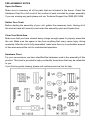
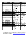
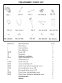
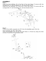
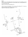
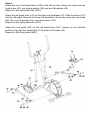
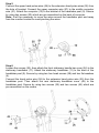
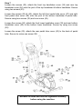
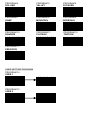
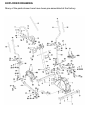
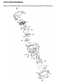
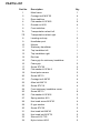
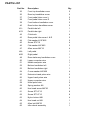
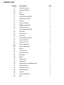
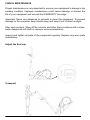
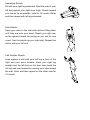
Gold Medal XT AG-14212
fit for life
with Roger Black
RFE 4250 Roger Back User Manuals.indd 7
23/10/2009 09:59
Dear Customer
We thank you for choosing your Roger Black Product and wish you every
success during your training.
Please read the User Manual and operation instructions carefully prior to
assembly and use, if you have questions please do not hesitate to contact us on
the following number or web site:
Customer service +44 (0) 0845 600 0464
Website www.rogerblackfitness.co.uk
E-mail [email protected]
Contents
Important Safety Instructions
2
Pre-assembly Notes
3
Assembly Steps
6
Computer Operation
11
Exploded Diagram
18
Parts List
20
Care & Maintenance
23
Stretching Routine
24
Limited Warranty
26
IMPORTANT SAFETY INSTRUCTIONS
Read all the instructions in this manual carefully before using your equipment
WARNING: Before beginning this or any exercise programme, consult your physician. This is
especially important for persons who have not exercised regularly before or persons with
pre-existing health problems. Read all instructions before using. Manufacturer assumes no
responsibility for personal injury or property damage sustained by or through the use of this
equipment.
1. It is the responsibility of the owner to ensure that all users of this equipment are
adequately informed of all warnings and precautions.
2. Use the equipment only as described in this manual.
3. Place on a level and stable surface, with 2 meters of clearance around it. To protect the
floor or carpet from damage, place a mat under this equipment.
4. Keep the equipment indoors, away from moisture or dust. Do not put the equipment in a
garage, shed, outbuilding or covered patio, or near water. Failure to do this will invalidate
your warranty and could cause serious safety problems.
5. Do not operate the equipment where aerosol products are used or where oxygen is being
administered.
6. Keep children under the age of 12 and pets away from the equipment all the times.
7. The equipment should not be used by persons weighting more than 110kg. Serious injury
may occur if the user weight exceeds the limit shown here.
8. The equipment complies with class HC of the standard EN957.
9. Never allow more than one person on the equipment at a time.
10. Wear appropriate exercise clothing when using the equipment. Do not wear loose
clothing that could become caught in the equipment. Athletic support clothes are
recommended for both men and women.
11. If you feel pain or dizziness while exercising, stop immediately and cool down.
12. The pulse sensor is not a medical device. Various factors, including the user’s movement,
may affect the accuracy of the heart rate readings. The pulse sensor is intended only as
an exercise aid in determining heart rate trends in general.
13. This equipment is intended for home use only. Do not use in a commercial or institutional
setting.
STORE THESE INSTRUCTIONS IN A SAFE PLACE FOR FUTURE REFERENCE
PRE-ASSEMBLY NOTES
Open the Boxes
Make sure to inventory all of the parts that are included in the boxes. Check the
Hardware Chart for a full count of the number of parts included for proper assembly.
If you are missing any parts please call our Technical Support line 0845 600 0464
Gather Your Tools
Before starting the assembly of your unit, gather the necessary tools. Having all of
the tools at hand will save time and make the assembly quick and hassle-free.
Clear Your Work Area
Make sure that you have cleared away a large enough space to properly assemble
the unit. Make sure the space is free from anything that many cause injury during
assembly. After the unit is fully assembled, make sure there is a comfortable amount
of free area around the unit for unobstructed operation.
Hardware Chart
For your convenience, we have identified the hardware used in the assembly of this
product. This chart is provided to help you identify those items that may be unfamiliar
to you.
If you find any parts missing, please call customer service line for help.
HARDWARE PARTS LIST
NO
Description
Q’ty
2
Carriage bolt M10*55
4
4
Flat washer Ф10*Ф25
6
5
Domed nut M10
4
21
Carriage bolt Ф8*20
4
22
Allen bolt M6*12
4
26
Flat washer Ф10*Ф32
2
27
Spring washer Ф10
2
28
Hex head screw M10*20
4
29
D type washer
2
31
Hex head bolt M8*45
4
32
Hex head bolt M10*78
2
33
Sleeve Ф12.7*65
2
34
Nylon locknut M10
2
42
Club knob
4
44
Flat washer Ф10*Ф22
2
46
Flat washer Ф8*Ф25
2
47
Allen screw M8*16
4
54
Curve washer Ф8*Ф20
4
59
Spring washer Ф8
2
60
Hex head screw M8*20
2
99
Allen Key L6
1
100
Allen Key L4
1
101
Wrench S13,17
2
Drawings
2
4
5
21
22
26
27
28
29
31
32
33
34
42
44
46
47
54
59
60
99
100
101
IF YOU’RE MISSING ANY PARTS PLEASE CALL TECHNICAL SUPPORT
ON 0845 600 0464 OR EMAIL: [email protected]
PRE-ASSEMBLY CHECK LIST
PART NO.
1
6
3
48L/R
10
11
12/13
9
41L/R
52/53
39/40
37/38
43
35/36
24/49
DESCRIPTION
Main Frame
Front stabilizer
Rear Stabilizer
Pedal L/R
Computer
Stationary handlebar
Upper handlebars L/R
Handlebar post
Pedal tube L/R
Lower handlebar L/R
Front & rear bottom handlebar cover
Front pedal tube cover L/R
Rear pedal tube cover L & R
Front & rear top handlebar cover
Front & rear stationary handlebar cover
Hardware pack
Manual
Q’TY
1
1
1
2
1
1
2
1
2
2
2
2
2
2
2
1
1
ASSEMBLY
Step 1
Attach the front stabilizer (6) to the front of the main frame (1) secure with two
carriage bolts (2), two flat washers (4), and two domed nuts (5).
Attach the rear stabilizer (3) to the rear of the main frame (1) secure with two
carriage bolts (2), two flat washers (4), and two domed nuts (5).
Step 2
Connect the middle computer wire (51) from the handlebar post (9) to the
lower computer wire (50). (See insert)
Insert the handlebar post (9) into the main frame (1). Secure by using four allen
screws (47) and four curved washers (54).
Step 3
Attach the lower left handlebar (52) to the left side axle of the handlebar post (9).
Secure by using D type washer (29), one flat washer (26), one spring washer (27),
one hex head screw (28).
Repeat for the bottom right handlebar (53).
Attach the upper left handlebar (12) to the lower left handlebar (52). Secure by
using two carriage bolts (21) and two allen bolts (22).
Repeat for the upper right handlebar (13).
Step 4
Attach the rear of left pedal tube (41R) to the left run disc. Secure by using one hex
head screw (60), one spring washer (59) and one flat washer (46).
Repeat for the right pedal tube (41R).
Attach the left pedal tube (41L) to the lower left handlebar (52). Slide the sleeve (33)
into the left pedal tube and the lower left handlebar. Secure by using one hex head
bolt (32), one flat washer (44), one nylon locknut (34).
Repeat for the right pedal tube (41R).
Attach the Left pedal (48L) to the left pedal tube (41L). Secure in your desired
position using two hex head bolts (31) and two club knobs (42).
Repeat for the Right pedal (48R).
Step 5
Connect the upper hand pulse wires (56) to the extension hand pulse wires (55) from
the hole of bracket. Connect the upper computer wire (57) to the middle computer
wire (51). Attach the computer (10) to the bracket of the handlebar post (9). Secure
by using two screws (20) which are pre-assembled on the back of computer.
Note: It will be necessary to move the wires around the handlebar post and away
from the monitor bracket to avoid pinching the wires.
Step 6
Loosen the screws (25), then attach the front stationary handle bar cover (24) to the
stationary handlebar (11). Attach the stationary handlebar (11) to the back of the
handlebar post (9). Secure by using two hex head screws (28) and two flat washers
(4).
Connect the hand pulse wire (58) to the extension hand pulse wire (55) from the
handlebar post. Then attach the rear stationary handlebar cover (49) to the
handlebar post. Secure by using two screws (25) and two screws (45) which are
pre-assembled on the covers.
Step 7
Loosen the screws (23), attach the front top handlebar cover (35) and rear top
handlebar cover (36) onto the joint of the top handlebar & bottom handlebar. Secure
using two screws (23).
Loosen the screws (25) & (45), attach the left front pedal tube cover (37) and right
front pedal tube cover (38) onto the joint of the bottom handlebar & pedal tube.
Secure using two screws (25) and one screw (45).
Loosen the screws (30), attach the front lower handlebar cover (39) and rear bottom
handlebar cover (40) to the bottom lower handlebar. Secure by using one screw
(30).
Loosen the screw (25), attach the rear pedal tube cover (43) to the back of pedal
tube. Secure by using one screw (25).
Recheck all bolts and nuts are tightened securely
before using the machine.
Computer Instructions
COMPUTER FRONT
The things you should know before exercise
A. Input Power
Plug in the adaptor to the equipment then the computer will beep. Press STOP
or ENTER to into the Manual mode.
B. Program select and setting value
1. Use the UP or DOWN keys to select program mode and then press ENTER to
confirm your exercise mode.
2. At the Manual mode, use the UP or DOWN keys to set up your
exercise TIME, DISTANCE, CALORIES, PULSE.
3. Press the START/STOP key to start exercise.
4. When you reach the set target, the computer will beep and then stop.
5. If you set up more than one target and you like to reach the next target, press
START/STOP key to continue exercising.
C. Wake-Up Function
The monitor will enter SLEEP mode (LCD off) when there is no signal input and
no key be pressed after around 4 minutes. Press any button on the screen to
start the monitor.
Functions and Features:
1. TIME: Shows your workout time in minutes and seconds. Your computer will
automatically count up from 0:00 to 99:59. You may also program your computer
to count down from a setting value ranges 1:00 to 99:00 by using the UP and
DOWN keys. If you continue exercising once the time has reached 0:00, the
computer will begin beeping, and reset itself to the original time set, letting you
know your workout is done.
2. DISTANCE: Displays the accumulated distance traveled during each workout up
to a maximum of 99.90KM.
3. SPEED: Displays your workout speed value in KM per hour.
4. RPM: Revolution Per Minute
5. WATT: The amount of mechanical power the computer is receiving from your
exercise.
6. CALORIES: Your computer will estimate the cumulative calories burned at any
given time during your workout.
7. PULSE: Your computer displays your pulse rate in beats per minute during your
workout.
8. AGE: Your computer is age-programmable from 10 to 99 years. If you do not set
an age, this function will always default to age 35.
9. TARGET HEART RATE (TARGET PULSE): The heart rate you should maintain
is called your Target Hear Rate in beats per minute.
10. PULSE RECOVERY: During the START stage, leave the both of your hands
holding on grips and then press “PULSE RECOVERY” key, time starts count
down from 00:60 - - to 00:00. As soon as 00:00 is reached, the computer will
show your heart rate recovery status with the grade F1.0 to F6.0.
1.0
means OUTSTANDING
1.0<F<2.0 means EXCELLENT
2.0≦F≦2.9 means GOOD
3.0≦F≦3.9 means FAIR
4.0≦F≦5.9 means BELOW AVERAGE
6.0
means POOR
Note: If no pulse signal input then the computer will show “P” on the PULSE
window. If the computer shows “ERR” on the message window, please re-press
the PULSE RECOVERY key and please make sure your hands are placed firmly
on the grips.
11. TEMPERATURE: Display the current temperature.
Key function:
There are 6 button keys and the function description as follows:
1. START/STOP key:
a. During the exercise mode, press the key to STOP exercise.
b. During the stop mode, press the key to START exercise.
2. UP key:
a. Press the key to increase the resistance during exercise mode.
b. During the setting mode, press the key to increase the value of Time, Distance,
Calories, Age and select Gender and Program.
3. DOWN key:
a. Press the key to decrease the resistance during exercise mode.
b. During the setting mode, press the key to decrease the value of Time, Distance,
Calories, Age and select Gender and Program.
4. ENTER key:
a. During the setting mode, press the key to accept the current data entry.
b. At the stop mode, by holding this key for over two seconds the user can reset all
values to zero or default value.
c. During setting the Clock, press this key to accept the setting of hour and setting
minute.
d. During exercise mode, press this key to Manual mode.
5. BODY FAT key: Press the key to input your HEIGHT, WEIGHT, GENDER and
AGE then to measure your body fat ratio,
6. PULSE RECOVERY key: Press the key to activate heart rate recovery function.
Program Introduction & Operation:
Manual Program: Manual
P1 is a manual program. User can start exercise by pressing START/STOP key. The
default resistance level is 5. Users may exercise in any desirous of resistance level
(Adjusting by UP/DOWN keys during the workout) with a period of time or a number
of calories or a certain distance.
Operations:
1. Use UP/DOWN keys to select the MANUAL (P1) program.
2. Press the ENTER key to enter MANUAL program.
3. The TIME will flash and you can press UP or DOWN keys to set your exercise
TIME. Press ENTER key to confirm your desired TIME.
4. The DISTANCE will flash and you can press UP or DOWN keys to set your target
DISTANCE. Press ENTER key to confirm your desired DISTANCE.
5. The CALORIES will flash and you can press UP or DOWN keys to set your
exercise CALORIES. Press ENTER key to confirm your desired CALORIES.
7. Press the START/STOP key to begin exercise.
Preset Program: Steps, Hill, Rolling, Valley, Fat Burn, Ramp, Mountain,
Intervals, Random, Plateau, Fartlek, Precipice Program
PROGRAM 2 to PROGRAM 13 are the preset programs. Users can exercise with
different level of resistance in different intervals as the profiles show. Users may
exercise in any desirous of resistance level (Adjusting by UP/DOWN keys during the
workout) with a period of time or a number of calories or a certain distance.
Operations:
1. Use UP/DOWN keys to select one of the above programs from P2 to P13.
2. Press the ENTER key to enter your workout program.
3. The TIME will flash and you can press UP or DOWN keys to set your exercise
TIME. Press ENTER key to confirm your desired TIME.
4. The DISTANCE will flash and you can press UP or DOWN keys to set your
target DISTANCE. Press ENTER key to confirm your desired DISTANCE.
5 The CALORIES will flash and you can press UP or DOWN keys to set your
exercise CALORIES. Press ENTER key to confirm your desired CALORIES.
6. The PULSE will flash and then you can press UP or DOWN keys to set your
exercise PULSE. Press ENTER key to confirm your desired Pulse.
7. Press the START/STOP key to begin exercise.
User Setting Program: User 1, User 2
Program 14 and 15 are the user setting program. Users are free to create the values
In the order of TIME, DISTANCE, CALORIES and the resistance level in 10
columns. The values and profiles will be stored in the memory after setup. Users
may also change the ongoing loading in each column by UP/DOWN keys, and they
will not change the resistance level stored in the memory.
Operations:
1. Use UP/DOWN keys to select the USER program from P14 to P15.
2. Press the ENTER key to enter your workout program.
3. The 1st column will flash, use the UP/DOWN keys to create your personal exercise
profile. Press ENTER to confirm your first column of exercise profile. The default
level is load 1.
4. Then column 2 will flash, use the UP/DOWN keys to create your personal
exercise profile. Press ENTER to confirm your second column of exercise profile.
5. Follow the above description 5 and 6 to finish your personal exercise profiles.
Press ENTER to confirm your desired exercise profile.
6. The TIME will flash and you can press UP or DOWN keys to set your exercise
TIME. Press ENTER key to confirm your desired TIME.
7. The DISTANCE will flash and you can press UP or DOWN keys to set your target
DISTANCE. Press ENTER key to confirm your desired DISTANCE.
8. The CALORIES will flash and you can press UP or DOWN keys to set your
exercise CALORIES. Press ENTER key to confirm your desired CALORIES.
9. The PULSE will flash and then you can press UP or DOWN keys to set your
exercise PULSE. Press ENTER key to confirm your desired Pulse.
10. Press the START/STOP key to begin exercise.
Body Fat Program: Body Fat
Program 16 is a special program for calculate users’ body fat ratio and offer a
specific resistance profile for users. There are 3 body types divided according to the
FAT% calculated.
Type1: BODY FAT% is more than (>) 27
Type2: 27 ≧ BODY FAT% ≧ 20
Type3: BODY FAT % is less than (<) 20
The computer will show the test results of FAT PERCENTAGE, BMI and BMR.
Operations:
1. Use UP/DOWN keys to select the BODY FAT (P24) program.
2. Press the ENTER key to enter your workout program.
3. The HEIGHT will flash and you can press UP or DOWN keys to set your HEIGHT.
Press ENTER key to confirm your HEIGHT. The default HEIGHT is 170cm or 5’07”
(5 feet 7 inches).
4. The WEIGHT will flash and you can press UP or DOWN keys to set your WEIGHT.
Press ENTER key to confirm your WEIGHT. The default WEIGHT is 70kgs or 155
lbs.
5. The GENDER will flash and you can press UP or DOWN keys to select your sex.
Number 1 means male and number 0 means female. Press ENTER key to confirm
your Gender. The default sex is 1 (MALE).
6. The AGE will flash and you can press UP or DOWN keys to set your AGE. Press
ENTER key to confirm your AGE. The default AGE is 35.
7. Press the START/STOP key to begin body fat measurement. If the window shows
E, please make sure that the palm of your hands are on the pulse grips. Then press
the START/STOP key again to begin body fat measurement.
8. After finished your measurement, the computer will show the values of FAT
PERCENTAGE, BMI and BMR on the LCD display. Furthermore, the computer will
show your own exercise profile for your body type.
9. Press START/STOP key to begin exercise.
Operation guide:
1. Sleep Mode:
The computer will enter the sleep mode when there is no signal input and no keys
are pressed around 4 minutes. You can press any key to wake up the computer.
2. BMI (Body Mass Index): BMI is a measure of body fat based on height and
weight that applies to both adult men and women.
3. BMR (Basal Metabolic Rate): Your Basal Metabolic Rate (BMR) shows the
number of calories your body needs to operate. This doesn’t account for any activity,
it’s simply the energy needed to sustain a heartbeat, breathing and normal body
temperature. It measures the body at rest, not sleep, at room temperature.
Error Message:
E1 (ERROR 1):
Normal state: During workout, If the monitor does not receive the count signal from
the gear motor for more than 4 seconds and after it has checked successively 3
times then the LCD will show E1.
Power on state: The gear motor will return to zero automatically, when the signal of
motor cannot be detected for more than 4 seconds then the gear motor’s driver will
be cut off immediately and show the E1 on the LCD display. All the other digital and
function mark are blank, and the output signals are cut off also.
E2 (ERROR 2): When the monitor read the memory data, if the I.D. code is not
correct or the memory IC damages then the monitor will show E2
immediately at power on.
E3 (ERROR 3): After 4 seconds by start mode, the computer detects the faulty motor
did not leave the zero point then the LCD bar displays “E3”.
Technical data of the current adapter
Available for Input: 230V/50Hz or 60Hz
Output: 6V AC/0.5A
LCD Workout Graphics
PRESET PROGRAM PROFILES:
PROGRAM 1
MANUAL
PROGRAM 2
STEPS
PROGRAM 3
HILL
PROGRAM 4
ROLLING
PROGRAM 5
VALLEY
PROGRAM 6
FAT BURN
PROGRAM 7
RAMP
PROGRAM 8
MOUNTAIN
PROGRAM 9
INTERVALS
PROGRAM 10
RANDOM
PROGRAM 11
PLATEAU
PROGRAM 12
FARTLEK
PROGRAM 13
PRECIPICE
USER SETTING PROGRAM
PROGRAM 14
USER 1
PROGRAM 15
USER 2
BODY FAT TEST PROGRAMS:
PROGRAM 16
BODY FAT (STOP MODE)
BODY FAT (START MODE)
One of the Following Six Profiles Will Display Automatically after Measuring Your BODY FAT:
Workout Time: 40 minutes
Workout Time: 40 minutes
Workout time: 20 minutes
Workout Time: 40 minutes
Workout Time: 40 minutes
Workout time: 20 minutes
EXPLODED DRAWING
Many of the parts shown here have been pre-assembled at the factory.
EXPLODED DRAWING
Many of the parts shown here have been pre-assembled at the factory.
PARTS LIST
Part No.
Description
Qty
1
Main frame
1
2
Carriage bolt M10*55
4
3
Rear stabilizer
1
4
Flat washer Ф10*Ф25
6
5
Domed nut M10
4
6
Front stabilizer
1
7L
Transportation wheel left
1
7R
Transportation wheel right
1
8
Leveling end cap
2
9
Handlebar post
1
10
Monitor
1
11
Stationary handlebar
1
12
Top handlebar left
1
13
Top handlebar right
1
14
End cap
2
15
Foam grip for stationary handlebar
1
16
Foam grip
2
17
Screw ST4*20
2
18
Flat washer Ф12*Ф4.2
2
19
Hand pulse sensor
2
20
Screw M5*10
2
21
Carriage bolt Ф8*20
4
22
Allen bolt M6*12
4
23
Screw ST4*16
4
24
Front stationary handlebar cover
1
25
Screw M5*10
8
26
Flat washer Ф10*Ф32
2
27
Spring washer Ф10
2
28
Hex head screw M10*20
4
29
D type washer
2
30
Screw ST4*30
2
31
Hex head bolt M8*45
4
32
Hex head bolt M10*78
2
33
Sleeve Ф12.7*65
2
34
Nylon locknut M10
2
PARTS LIST
Part No.
Description
Qty
35
Front top handlebar cover
2
36
Rear top handlebar cover
2
37
Front pedal tube cover L
2
38
Front pedal tube cover R
2
39
Front bottom handlebar cover
2
40
Rear bottom handlebar cover
2
41L
Pedal tube left
1
41R
42
Pedal tube right
1
Club knob
4
43
Rear pedal tube cover L & R
2
44
Flat washer Ф10*Ф22
2
45
Screw ST4*16
4
46
Flat washer Ф8*Ф25
2
47
Allen screw M8*16
4
48L
Left pedal
1
48R
Right pedal
1
49
Rear stationary handlebar cover
1
50
Lower computer wire
1
51
Middle computer wire
1
52
Bottom handlebar left
1
53
Bottom handlebar right
1
54
Curve washer Ф8*Ф20
4
55
Extension hand pulse wire
2
56
Upper hand pulse wire
2
57
Upper computer wire
1
58
Hand pulse wire
2
59
Spring washer Ф8
2
60
Hex head screw M8*20
2
61
Screw ST3.5*15
8
62
Screw ST3.5*10
8
63
Nylon locknut M8
4
64
Hex head nut M8
1
65
Allen bolt M8*55
1
66
Idler wheel assembly
1
PARTS LIST
Part No.
67
Description
Qty
Powder spacer
1
68
Allen bolt M8*20
1
69
Clip
2
70
Bearing
2
71
Hex head bolt M6*25
1
72
Hex head nut M6
2
73
Spring
1
74
Sensor bracket
1
75
Magnet assembly
1
76
Powder spacer
2
77
Hex head bolt M8*55
1
78
Run disc
2
79
France nut
4
80
Flywheel
1
81
Flat washer Φ8*Φ17
2
82
Screw ST5*15
4
83
Screw ST5*15
13
84L
Chain cover left
1
84R
Chain cover right
1
85
Pulley
1
86
Cross crank
2
87
Run disc cover
2
88
Bushing
2
89
Motor
1
90
Power wire
1
91
Motor wire
1
92
Inner cap for handlebar post
1
93
Plastic spacer
2
94
End cap for wire
1
95
Plastic spacer
4
96
U plate
2
97
Allen bolt M8*50
2
98
Belt
1
CARE & MAINTENANCE
Proper maintenance is very important to ensure your equipment is always in top
working condition. Improper maintenance could cause damage or shorten the
life of your equipment and exceed the WARRANTY coverage.
Important: Never use abrasives or solvents to clean the equipment. To prevent
damage to the computer, keep liquids away and keep it out of direct sunlight.
After each workout: Wipe off the console and other frame surfaces with a clean,
water dampened soft cloth to remover excess perspiration.
Inspect and tighten all parts of the equipment regularly. Replace any worn parts
immediately.
Adjust the End cap
Transport
STRETCHING ROUTINE
Warm Up and Cool Down:
A successful exercise programme consists of a warm-up, aerobic exercise, and a
cool-down. Warming up is and important part of your workout, and should begin
every session. It prepares your body for more strenuous exercise by heating up and
stretching out your muscles, increasing your circulation and pulse rate, and
delivering more oxygen to your muscles. At the end of your workout, repeat these
exercises to reduce sore muscle problems. We suggest the following warm-up and
cool-down exercises:
Toe Touch:
Slowly bend forward from your waist, letting your
back and shoulders relax as you stretch toward your
toes. Reach down as far as you can and hold for 15
counts
Shoulder Lift:
Lift your right shoulder up toward your ear for one
count. Then lift your left shoulder up for one count as
you lower your right shoulder.
Head Roll:
Rotate your head to the right for one count, feeling
the stretch up the left side of your neck. Next, rotate
your head back for one count, stretching your chin to
the ceiling and letting your mouth open. Rotate your
head to the left for one count, and finally, drop your
head to your chest for one count.
Hamstring Stretch:
Sit with your right leg extended. Rest the sole of your
left foot against your right inner thigh. Stretch toward
your toe as far as possible. Hold for 15 counts. Relax
and then repeat with left leg extended.
Side Stretch:
Open your arms to the side and continue lifting them
until they are over your head. Reach your right arm
as far upward toward the ceiling as you can for one
count. Feel the stretch up your right side. Repeat this
action with your left arm.
Calf-Achilles Stretch:
Lean against a wall with your left leg in front of the
right and your arms forward. Keep your right leg
straight and the left foot on the floor; then bend the
left leg and lean forward by moving your hips toward
the wall. Hold, and then repeat on the other side for
15 counts.
LIMITED WARRANTY
This product is warranted to be free from defects in workmanship and material,
under normal use and service conditions, far a period of two years from the date of
purchase. This warranty extends only to the original purchaser. This warranty is
limited to replacing or repairing, at the manufacturer’s option, the product through
one of its authorized service centres. All repairs for which warranty claims are made
must be authorized by the manufacturer. This warranty does not extend to any
product or damage to the product caused by or attributable to freight damage, abuse,
misuse, improper or abnormal usage or repairs not provided by an authorized
service centre, products used for commercial or rental purposes, or products used
as store display models. No other warranty beyond that specifically set forth above is
authorized.
The manufacturer is not responsible or liable for indirect, special or consequential
damages arising out of or in connection with the use of performance of the product
or damages with respect to any economic loss, loss of property, loss of property, loss
of revenues or profits, loss of enjoyment or use, costs of removal, installation or
other consequential damages of whatsoever nature.
Excluded from warranty are wearing parts and damages caused by misuse of the
product. In case of claim please contact your specialist dealer. The warranty period
starts at the date the product was purchased (please carefully retain your sales
receipt). Our quality products have been designed and tested to meet the needs and
requirements of a committed Fitness-Training of in-home use. This product is tested
to the European Standard EN957
Customer Service: +44 (0) 0845 600 0464
To achieve the best support in case of a problem with your product, we would ask
you to please quote the product Model Name and Serial Number.
These can be found on the sticker underside your product.
Model name: _____________________________
Serial number: ____________________________
Spare Parts Order:
If you require any parts for your machine please contact Technical Support on
0845 600 0464
Please have your machine serial number and production date to hand.
Waste Disposal
Please discard product in accordance with local environmental laws, regulations and
WEEE directive.
Gold Medal XT AG-14212
User manual.
For information on the Roger Black Medal
Series visit www.rogerblackfitness.co.uk
For technical support call the Roger Black
Technical Support Line on 0845 600 0464,
or email [email protected]
RFE 4250 Roger Back User Manuals.indd 8
23/10/2009 09:59