1
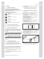
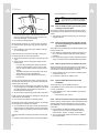
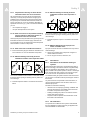
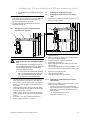
Installation manual
For the competent person
Installation manual
Air/flue gas system
VKK ../3
GB
Legal information
Document type:
Installation manual
Product:
Target group:
Air/flue gas system
– 130 mm diameter system
– 160 mm diameter system
– 200 mm diameter system
Authorised competent person
Language:
EN
Document number_version:
0020058722_04
Created on:
26.09.2012
Publisher/manufacturer
Vaillant GmbH
Berghauser Str. 40 D-42859 Remscheid
Telefon +49 21 91 18‑0 Telefax +49 21 91 18‑28 10
[email protected] www.vaillant.de
© Vaillant GmbH 2012
These instructions, or extracts thereof, may only be printed with the written consent of Vaillant GmbH.
All designations of products in these instructions are brand names/trade marks of the companies in question.
We reserve the right to make technical changes.
Contents
Contents
1
Notes on the documentation .............................. 4
1.1
Observing other applicable documents ................. 4
1.2
Storing documents................................................. 4
1.3
Applicability of the instructions .............................. 4
2
Safety .................................................................... 5
2.1
Action-related warnings ......................................... 5
2.2
Required personnel qualifications ......................... 5
2.3
General safety information .................................... 5
2.4
Intended use .......................................................... 7
2.5
Regulations (directives, laws, standards) .............. 8
3
System overview.................................................. 9
3.1
Combination options for systems with VKK........... 9
3.2
130 mm diameter system ...................................... 9
3.3
160 mm diameter, 200 mm diameter system ........ 9
4
Certified air/flue gas systems and
components ....................................................... 11
4.1
Certified air/flue gas systems and components,
130 mm diameter................................................. 11
4.2
Certified air/flue gas systems and components,
160 mm diameter................................................. 11
4.3
Certified air/flue gas systems and components,
200 mm diameter................................................. 11
4.4
Certified flue gas systems.................................... 12
5
System conditions............................................. 12
5.1
Maximum pipe lengths......................................... 12
5.2
General installation instructions........................... 17
6
Installing the 130 mm diameter system........... 18
6.1
Installation instructions ........................................ 18
6.2
Installing the basic set for shaft installation ......... 19
6.3
Flue gas connection and installing the
horizontal flue gas pipe........................................ 20
6.4
Installing the combustion air line ......................... 21
7
Installing the 160 mm diameter and 200 mm
diameter systems .............................................. 22
7.1
Installing the flue gas pipe in the shaft ................ 22
7.2
Installing a flue gas pipe on a support pipe
(optional).............................................................. 25
7.3
Installing the vertical roof duct ............................. 25
7.4
Installing the flue gas pipe on the external
wall....................................................................... 26
7.5
Stabilising the flue gas pipe ................................. 30
7.6
Flue gas connection and installing the
horizontal flue gas pipe........................................ 31
7.7
Installing the combustion air line ......................... 31
8
Customer service............................................... 32
Index ................................................................................... 33
0020058722_04 Air/flue gas system Installation manual
3
1 Notes on the documentation
1
1.1
Notes on the documentation
Observing other applicable documents
For the competent person:
–
1.2
▶
Installation instructions for the installed Vaillant product.
Storing documents
Pass these instructions and all other applicable documents on to the system operator.
The system operator should retain these instructions for further use.
1.3
Applicability of the instructions
These instructions apply only for the Vaillant heat generator
named in the other applicable documents and referred to as
the "product" in this document.
4
Installation manual Air/flue gas system 0020058722_04
Safety 2
2
Safety
2.1
▶
Action-related warnings
Classification of action-related warnings
The action-related warnings are classified in accordance
with the severity of the possible danger using the following
warning signs and signal words:
Warning symbols and signal words
Danger!
Imminent danger to life or risk of severe personal
injury
Danger!
Risk of death from electric shock
As part of the annual maintenance, inspect the flue gas
system in terms of:
– external faults such as brittleness and damage
– safe pipe connections and secure fastenings
2.3.3
Risk of death from leaks in the flue gas
route
Flue gas may escape from leaking pipes or damaged seals.
Mineral-oil-based greases can damage the seals.
▶
▶
▶
Warning.
Risk of minor personal injury
▶
▶
Caution.
Risk of material or environmental damage
▶
Transport the pipes to the installation site only in the original packaging.
If the temperature is lower than 0 °C, warm the pipes
before beginning installation.
When installing the flue gas installation, use only flue
pipes of the same material.
Do not install any damaged pipes.
When connecting, always slide the pipes into the sleeve
until they reach a stop.
Shorten the flue pipes to the suitable lengths at right
angles along their smooth side.
15°
2.2
Required personnel qualifications
These instructions are intended for the competent person.
5mm
2.2.1
Authorised competent person
The installation, assembly and removal, start-up, maintenance, repair and decommissioning of Vaillant products and
accessories must only be carried out by authorised competent persons.
Note
Each competent person is qualified for specific
activities on the basis of their training. They must
only work on units if they have the required qualification.
▶
▶
▶
File off sharp burrs and chamfer the ends of the pipes before assembling them so that the seals are not damaged,
and dispose of the shavings.
Never use mineral-oil-based grease for the installation.
Only 130 mm diameter systems: if necessary, only use
water to facilitate installation.
When working on the units, the competent persons must
observe all applicable directives, standards, laws and other
regulations.
2.3
General safety information
2.3.1
Informing the responsible departments
▶
Before installing the flue pipe, inform the local gas supply
company and the district master chimney sweep.
2.3.2
▶
Only 160 mm diameter and 200 mm diameter systems:
Use the lubricant supplied to facilitate installation.
Risk of poisoning due to escaping flue gas
Improperly installed flue gas pipes may cause flue gas to
escape.
▶
Before starting up the product, check that the whole flue
pipe is securely fastened and sealed.
The flue gas pipe may become damaged by unforeseeable
external influences.
0020058722_04 Air/flue gas system Installation manual
5
2 Safety
–
Note
3° corresponds to a downward gradient of
approx. 50 mm per metre of pipe length.
1
2.3.4
2
▶
▶
When fitting the flue pipes, make absolutely sure the
seals are correctly positioned. The lip of the seal must
be facing inwards (1), not outwards (2).
Do not use any damaged seals.
Mortar residues, shavings, etc. in the flue pipe may restrict
the outward flow of the flue gas. Flue gas may escape into
the room.
▶
After installation, remove all mortar residues, shavings,
etc. from the flue pipe.
▶
Secure each extension to the wall or ceiling using a pipe
clamp.
Where possible, use the original pipe clamps from the
product range.
– If you are using standard pipe clamps, the tensioning range must be between 130 mm, 160 mm and
200 mm, and the bearing capacity must be at least
200 kg.
– The distance between two pipe clamps must not be
greater than the length of the extension.
– The pipe clamps must be isolated from structureborne sound.
The flue gas pipe expands when warm. If the pipes are obstructed when expanding, this may lead to a forced fracture
and flue gases will escape.
▶
▶
Secure each of the pipe clamps to the wall or the ceiling
using a hanger bolt or threaded bolt M8/M10. This allows
for sufficient elasticity of the fastening in the event of
thermal expansion of the pipes.
Secure the pipe clamps using hanger bolts or stud bolts.
▶
Do not secure any loads to the flue gas guiding.
Mechanical impact loading of the flue gas pipe may damage
the flue gas pipe. Flue gases may escape.
▶
Do not install the flue gas pipe in areas with mechanical
impact loading. The flue gas pipe can also be protected
against impact using protection devices that are created
on-site.
Standing condensate can damage the seals of the flue gas
pipe.
▶
6
The openings of the flue pipe must only be opened by a
competent person.
2.3.5
Risk of fire and electronic damage caused
by missing lightning protection for the flue
gas installation
The product may be damaged by the effects of lightning and
this may lead to fires.
▶
▶
If the building is equipped with a lightning protection system, incorporate the air/flue gas pipe into the lightning
protection.
If the vertical flue gas pipe contains materials made from
metal, incorporate it into the potential balancing system.
2.3.6
Risk of injury from snow falling from roofs
Where flue pipes penetrate the roof skin, the water vapour
contained in flue gas may precipitate as ice on the roof or the
roof structures in unfavourable weather conditions.
▶
▶
At the installation site, ensure that this ice build-up does
not slide from the roof.
If necessary, install an ice collection mesh.
2.3.7
Risk of suffocation from lack of rear
ventilation
The flue gas pipe is not ventilated from behind.
If the installation room for the product is not ventilated, there
is a risk of suffocation.
▶
Loads on the flue gas guiding may damage the flue gas pipe
and lead to flue gas escaping.
▶
Risk of death from flue gas escaping from
openings in the flue pipe
All openings in the flue pipe that can be opened for inspection purposes must be closed before start-up and during operation.
Extensions that are not secured to the wall or ceiling may
bend and separate due to thermal expansion.
▶
Downward gradient to the product: 3°
In the installation room, build a ventilation opening that
leads outside.
– Cross-sectional area: 150 cm²
2.3.8
Risk of corrosion in the flue gas installation
Sprays, solvents, cleaning agents, paints and adhesives may
contain substances that could lead to corrosion in the flue
gas installation in some circumstances when the product is
in operation.
▶
▶
Ensure that the combustion air that is guided to the
product is kept free of chemical substances that may
contain fluorine, chlorine, or sulphur, for example.
Only use appropriate Vaillant components for installing
the flue gas guiding.
Route the horizontal flue pipe with a downward gradient.
Installation manual Air/flue gas system 0020058722_04
Safety 2
2.3.9
Inspect/clean chimneys to which former
solid fuel boilers were once connected
We recommend that you have chimneys inspected and
cleaned by a chimney sweep before the flue gas pipe is
installed if these chimneys were previously used to divert
flue gas away from solid-fuel-fired boilers but should now
supply combustion air. If it is not possible to adequately inspect/clean the chimney (e. g. due to construction features),
you can
–
–
2.3.13 Moisture damage caused by incorrect
installation location of the inspection Tpiece
use a separate air supply or
use open-flued operation for the system.
2.3.10 Risk of corrosion in the product caused by
using a chimney to which the former oilfired boiler was once connected
An incorrect installation location leads to condensate leaking
from the lid of the opening for cleaning and may lead to corrosion damage.
Chimneys that previously diverted the flue gas away from oilfired boilers should not be used to supply combustion air.
▶
The combustion air may be charged with chemical deposits
and this leads to corrosion in the product.
2.3.11 Risk of fire due to insufficient clearance
▶
Ensure that the flue gas pipe outside the shaft has a minimum clearance of 5 cm from flammable components.
2.3.12 Moisture damage caused by incorrect
installation location of the inspection elbow
Install the inspection T-piece in accordance with the illustration.
2.3.14 Material damage due to improper use
and/or unsuitable tools
Improper use and/or the use of unsuitable tools may result in
material damage.
▶
▶
Always use a suitable open-end spanner to tighten or
undo threaded connections.
Do not use pipe wrenches, extensions, etc.
2.4
Intended use
2.4.1
Intended use of the Vaillant air/flue gas
systems
Vaillant air/flue gas systems are constructed using state-ofthe-art technology in accordance with the recognised safety
rules and regulations. Nevertheless, there is still a risk of
injury or death to the system operator or others or of damage
to the products and other property in the event of improper
use or use for which the products are not intended.
An incorrect installation location leads to condensate leaking
from the lid of the opening for cleaning and may lead to corrosion damage.
The Vaillant air/flue gas systems named in this manual must
only be used in combination with the product types named in
this manual.
▶
Any other use that is not specified in these instructions, or
use beyond that specified in this document, shall be considered improper use.
Install the inspection elbow in accordance with the illustration.
Intended use includes the following:
–
–
–
observance of accompanying operating, installation and
servicing instructions for the Vaillant product as well as
for all other components of the system
installing and fitting the product in accordance with the
product and system approval
compliance with all inspection and maintenance conditions listed in the instructions.
2.4.2
CE certification
The products are certified as boiler systems with attached
flue gas installation according to the EU gas appliances directive 90/396/EEC or 2009/142/EC.
0020058722_04 Air/flue gas system Installation manual
7
2 Safety
This installation manual is a component of the certification
and is cited in the type testing certificate. In compliance
with the regulatory statutes of this installation manual, the
proof of usability of the products identified by Vaillant article
numbers that are designed for the flue pipe is provided. If
you do not use certified elements for the Vaillant flue pipe
when installing the products, this voids the CE conformity of
the product. We therefore strongly recommend that you fit
Vaillant air/flue gas systems.
2.5
Regulations (directives, laws, standards)
Please observe the existing national rules and regulations,
standards, laws and guidelines.
8
Installation manual Air/flue gas system 0020058722_04
System overview 3
3
System overview
3.2.3
Flue gas pipe in the shaft, combustion air
from the shaft
Observe the maximum pipe lengths, see "Maximum pipe
lengths" (→ Page 12).
3.1
Combination options for systems with VKK
130 mm diameter
160 mm diameter
200 mm diameter
VKK 806/3-E-HL
VKK 1206/3-E-HL
VKK 1606/3-E-HL
VKK 806/3-E-HL
VKK 1206/3-E-HL
VKK 1606/3-E-HL
VKK 2006/3-E-HL
VKK 2406/3-E-HL
VKK 2806/3-E-HL
3.2
130 mm diameter system
3.2.1
Flue gas pipe in the shaft, combustion air
from the installation room
▶
▶
Installing the 130 mm diameter system (→ Page 18)
3.3
160 mm diameter, 200 mm diameter system
3.3.1
Flue gas pipe in the shaft, combustion air
from the installation room
Installing the 130 mm diameter system (→ Page 18)
3.2.2
Flue gas pipe in the shaft, combustion air
through the external wall
▶
▶
Installing the flue gas pipe in the shaft (→ Page 22)
Flue gas connection and installing the horizontal flue gas
pipe (→ Page 31)
3.3.2
▶
Flue gas pipe in the shaft, combustion air
through the external wall
Installing the 130 mm diameter system (→ Page 18)
▶
▶
▶
0020058722_04 Air/flue gas system Installation manual
Installing the flue gas pipe in the shaft (→ Page 22)
Installing the combustion air line in the external wall
(→ Page 31)
Flue gas connection and installing the horizontal flue gas
pipe (→ Page 31)
9
3 System overview
3.3.3
Flue gas pipe in the shaft, combustion air
from the shaft
▶
Flue gas connection and installing the horizontal flue gas
pipe (→ Page 31)
3.3.6
▶
▶
▶
Installing the flue gas pipe in the shaft (→ Page 22)
Installing the combustion air line in the shaft (→ Page 31)
Flue gas connection and installing the horizontal flue gas
pipe (→ Page 31)
3.3.4
Flue gas pipe through the roof, combustion
air from the installation room
1.
Installing the flue gas pipe on the external wall
(→ Page 26)
2.
Flue gas connection and installing the horizontal flue
gas pipe (→ Page 31)
3.3.7
▶
▶
Flue gas connection and installing the horizontal flue gas
pipe (→ Page 31)
Flue gas pipe through the roof, combustion
air through the external wall
▶
Installing the flue gas pipe on the external wall
(→ Page 26)
▶
Installing the combustion air line in the external wall
(→ Page 31)
Flue gas connection and installing the horizontal flue gas
pipe (→ Page 31)
▶
10
Flue gas pipe on the external wall,
combustion air through the external wall
Installing the roof duct (→ Page 26)
3.3.5
▶
▶
Flue gas pipe on the external wall,
combustion air from the installation room
Installing the roof duct (→ Page 26)
Installing the combustion air line in the external wall
(→ Page 31)
Installation manual Air/flue gas system 0020058722_04
Certified air/flue gas systems and components 4
4
4.1
Certified air/flue gas systems and
components
Certified air/flue gas systems and
components, 130 mm diameter
Components
Art. no.
Flat roof penetration collar (aluminium), for the
roof duct, 160/186 mm diameter
0020095570
External wall connection (stainless steel), elbow,
support console, external collar, 160/225 mm
diameter
0020095573
Components
Art. no.
Basic set for shaft installation (PP),
130 mm diameter
0020042762
External wall pipe bracket (stainless steel),
225 mm diameter
0020095575
Spacer (PP), 7 pcs, 130 mm diameter
0020042763
Extension (stainless steel) for external wall
laying, 0.5 m, concentric, 160/225 mm diameter
0020095577
Inspection opening with cover (PP),
130 mm diameter
0020042764
Extension (stainless steel) for external wall
laying, 1.0 m, concentric 160/225 mm diameter
0020095579
87° elbow (PP), 130 mm diameter
0020042765
0020095581
45° elbow (PP), 130 mm diameter
0020042766
Vertical roof duct (stainless steel) for external
wall laying, concentric, 160/225 mm diameter
30° elbow (PP), 130 mm diameter
0020042767
0020095583
15° elbow (PP), 2 pcs, 130 mm diameter
0020042768
Opening piece (stainless steel), 160/225 mm
diameter
Extension (PP), 1.0 m, 130 mm diameter
0020042769
Extension (PP), 2.0 m, 130 mm diameter
0020042770
Extension (PP), 0.5 m, 150 mm diameter
0020095543
Basic set for air intake, 130 mm diameter
0020060591
Tile for pitched roof for 160/225 mm diameter
system, dependent on the angle
15° - 25°
25° - 35°
35° - 45°
0020095585
0020130600
0020130601
Flat roof penetration collar (stainless steel) for
160/225 mm diameter system, stainless steel
0020095587
Inspection element (stainless steel), 0.4 m,
160/225 mm diameter
0020095589
Support elbow mounting rail, long version, 500
mm
0020095539
4.2
Certified air/flue gas systems and
components, 160 mm diameter
Components
Art. no.
Unit connection (PP) with measurement opening, 150 – 160 mm diameter
0020095531
Air clamp (stainless steel) for 160/225 mm
diameter
0020095540
Basic set for shaft installation (PP), 160 mm
diameter
0020095533
45° elbow (stainless steel) for external wall
laying, concentric, 160/225 mm diameter
0020095544
Set for air intake (PP), 160 mm diameter
0020095535
Fastening clamp, 160 mm diameter
0020151162
End pipe (stainless steel), 0.5 m, 160 mm diameter
0020095537
Installation aid with a line loop, 160 mm diameter
0020095541
Extension (PP), 0.5 m, 160 mm diameter
0020095545
Extension (PP), 1.0 m, 160 mm diameter
0020095546
Extension (PP), 2.0 m, 160 mm diameter
0020095547
4.3
Certified air/flue gas systems and
components, 200 mm diameter
Components
Art. no.
Unit connection (PP) with measurement opening,
200 mm diameter
0020095532
87° elbow (PP), 160 mm diameter
0020095552
0020095554
Basic set for shaft installation (PP), 200 mm
diameter
0020095534
87° elbow (PP) with inspection opening,
160 mm diameter
0020095556
End pipe (stainless steel), 0.5 m, 200 mm diameter
0020095538
45° elbow (PP), 160 mm diameter
30° elbow (PP), 160 mm diameter
0020095558
Installation aid with line loop, 200 mm diameter
0020095542
15° elbow (PP), 160 mm diameter
0020095560
Extension (PP), 0.5 m, 200 mm diameter
0020095549
Extension (PP), 1.0 m, 200 mm diameter
0020095550
Extension (PP), 2.0 m, 200 mm diameter
0020095551
Inspection element (PP) 0.21 m, 160 mm diameter
0020095561
Spacer (1 pc), 160 mm diameter
0020095563
87° elbow (PP), 200 mm diameter
0020095553
Spacer (4 pcs), 160 mm diameter
0020095565
0020095555
Vertical roof duct (PP), concentric, 160/186 mm
diameter
0020095567
87° elbow (PP) with inspection opening, 200 mm
diameter
45° elbow (PP), 200 mm diameter
0020095557
Universal pitched roof tile (25° - 45°), black, for
roof duct, 160/186 mm diameter
0020095568
30° elbow (PP), 200 mm diameter
0020095559
0020095569
Inspection element (PP), 0.5 m, 200 mm diameter
0020095562
Universal pitched roof tile (25° - 45°), red, for
roof duct, 160/186 mm diameter
0020058722_04 Air/flue gas system Installation manual
11
5 System conditions
Components
Art. no.
Spacer (stainless steel), 1 pc, 200 mm diameter
Note:
The spacer is bent in its film packaging. In the
as-delivered condition, the struts are straight.
The spacers must be put back into their round
shape before the installation.
0020095564
Spacer (stainless steel), 4 pcs, 200 mm diameter
0020095566
Spacer (stainless steel), 10 pcs, 200 mm diameter
0020106436
External wall connection (stainless steel),
200/300 mm diameter, elbow, support console,
external collar
0020095574
External wall pipe bracket (stainless steel),
300 mm diameter
0020095576
Extension (stainless steel) for external wall laying, 0.5 m, concentric, 200/300 mm diameter
0020095578
Extension (stainless steel) for external wall laying, 1.0 m, concentric, 200/300 mm diameter
0020095580
Vertical roof duct (stainless steel) for external
wall laying, concentric, 200/300 mm diameter
0020095582
Opening piece (stainless steel), 200/300 mm
diameter
0020095584
Tile for pitched roof for 200/300 mm diameter
system, dependent on the angle:
15° - 25°
25° - 35°
35° - 45°
0020095586
0020130602
0020130603
Flat roof penetration collar (stainless steel) for
200/300 mm diameter system
0020095588
Inspection element (stainless steel) 0.66 m,
200/300 mm diameter
0020095590
Support elbow mounting rail, long version, 500
mm
0020095539
Air clamp (stainless steel) for 200/300 mm diameter
0020095536
45° elbow (stainless steel) for external wall
laying, concentric, 200/300 mm diameter
0020095548
Fastening clamp, 200 mm diameter
0020151163
4.4
5
System conditions
5.1
Maximum pipe lengths
5.1.1
Notes on the illustrations and the tables
Total pipe length L = L1 + L2 ...+ L3 ...+ L4 (of which max.
10.0 m is in the cold area, exterior external wall system).
When installing diversions in addition to those specified in
the tables, the maximum total pipe length L is reduced as
follows:
–
–
by 1 m for each 87° diversion in the flue gas line and air
pipe
by 0.5 m for each 45° diversion in the flue gas line and
air pipe
Pipe diameter for air supply through the shaft or external
wall:
–
–
Diameter of the 130 mm flue gas pipe: Minimum diameter
of the 130 m supply line
Diameter of the 160 mm or 200 mm flue gas pipe: Minimum diameter of the 160 m supply line.
Maximum vertical height in the shaft if flue gas pipe is
130 mm in diameter: 30 m
Maximum shaft cross-section for 130 mm diameter flue gas
pipe in the shaft:
–
–
Angular: 230 x 230 mm
Round: 280 mm
For the combustion air guiding through the external wall, the
air intake port must not be in any wind pressure area other
than the flue gas opening.
Certified flue gas systems
The certification also documents that the flue gas systems
are suitable for use with the product in accordance with the
instructions that are valid up to 08/2012.
12
Installation manual Air/flue gas system 0020058722_04
System conditions 5
Flue gas pipe in the shaft, combustion air from the installation room
L3
m
in
.1
m
5.1.2
L2
L1
ecoCRAFT VKK../3-E-HL
806
1206
Shaft cross-section:
At least
System
130 mm
diameter
160 mm
diameter
200 mm
diameter
Round: DN + 60 mm
Angular: DN + 40
mm
1606
2006
2406
2806
Maximum total pipe length (L1 + L2 + L3)
33.0 m
plus 3 x 87° diversions and support elbow
‒
50.0 m
plus 3 x 87° diversions and support elbow
‒
‒
50.0 m
plus 3 x 87° diversions and support elbows
The horizontal flue gas pipe must have a maximum length of 6 m, minus the three 87° diversions.
Flue gas pipe in the shaft, combustion air through the external wall
L3
5.1.3
L1
L2
L4
0020058722_04 Air/flue gas system Installation manual
13
5 System conditions
ecoCRAFT VKK../3-E-HL
806
System
130 mm
diameter
160 mm
diameter
Shaft cross-section:
At least
1206
1606
2006
2406
2806
Maximum total pipe length (L1 + L2 + L3 + L4)
40.0 m
plus 1 x diversion 87° and
support elbow
Round: DN + 60 mm
Angular: DN + 40
mm
38.0 m
plus 1 x
diversion 87°
and support
elbow
‒
50.0 m
plus 1 x diversion 87° and support elbow
‒
‒
50.0 m
plus 1 x diversion 87° and support elbow
200 mm
diameter
The horizontal lines must have a maximum length of 12 m, minus the two 87° diversions, of
which 6 m is for the air pipe and max. 6 m is for the flue gas pipe.
Flue gas pipe in the shaft, combustion air from the shaft
L3
5.1.4
L1
L2
L2
ecoCRAFT VKK../3-E-HL
806
System
Shaft cross-section:
At least
Round: DN + 80 mm
Angular: DN + 60
mm
Round: DN + 100
mm
Angular: DN + 80
mm
14
1606
2006
2406
2806
Maximum total pipe length (L1 + L2 + L3)
Round: DN + 60 mm
Angular: DN + 40
mm
130 mm
diameter
1206
27.0 m
17.0 m
30.0 m
35.0 m
‒
35.0 m
35.0 m
Installation manual Air/flue gas system 0020058722_04
System conditions 5
ecoCRAFT VKK../3-E-HL
806
System
130 mm
diameter
1206
Shaft cross-section:
At least
1606
2006
2406
2806
Maximum total pipe length (L1 + L2 + L3)
Round: DN + 120
mm
Angular: DN + 100
mm
35.0 m
35.0 m
Round: DN + 70 mm
Angular: DN + 40
mm
‒
35.0 m
39.8 m
Round: DN + 90 mm
Angular: DN + 60
mm
160 mm
diameter
Round: DN + 120
mm
Angular: DN + 80
mm
50 m
‒
50 m
50 m
Round: DN + 140
mm
Angular: DN + 100
mm
Round: DN + 70 mm
Angular: DN + 40
mm
38.6 m
26,3
50 m
50 m
Round: DN + 90 mm
Angular: DN + 60
mm
200 mm
diameter
Round: DN + 120
mm
Angular: DN + 80
mm
‒
50 m
Round: DN + 140
mm
Angular: DN + 100
mm
–
plus 1 x diversion 87° and support elbow
–
The horizontal lines must have a maximum length of 12 m, minus the 87° diversion, of which
max. 6 m is for the air pipe and max. 6 m is for the flue gas pipe.
0020058722_04 Air/flue gas system Installation manual
15
5 System conditions
Flue gas pipe through the roof, combustion
air from the installation room
5.1.6
Flue gas pipe through the roof, combustion
air through the external wall
L3
L3
m
m
in
in
.
. 1m
1m
5.1.5
L2
L1
L2
L1
L4
ecoCRAFT VKK../3-E-HL
806
ecoCRAFT VKK../3-E-HL
806
1206
1606
2006
2406
2806
System
Maximum total pipe length (L1 + L2 + L3)
130 mm
diameter
‒
160 mm
diameter
200 mm
diameter
25.0 m
plus 3 diversions 87°
‒
‒
25.0 m
plus 3 diversions 87°
The horizontal flue gas pipe must have a maximum length of 6 m, minus the three 87° diversions.
16
1206
1606
2006
2406
System
Maximum total pipe length
(L1 + L2 + L3+ L4)
130 mm
diameter
‒
160 mm
diameter
200 mm
diameter
25.0 m
plus 2 diversions 87°
‒
2806
‒
25.0 m
plus 2 diversions 87°
The horizontal lines must have a maximum length
of 12 m, minus the two 87° diversions, of which
6 m is for the air pipe and max. 6 m is for the flue
gas pipe.
Installation manual Air/flue gas system 0020058722_04
System conditions 5
Flue gas pipe on the external wall,
combustion air from the installation room
5.1.8
Flue gas pipe on the external wall,
combustion air through the external wall
L3
L3
m
m
in.
1m
in
.1
m
5.1.7
L2
L1
L1
L2
L4
ecoCRAFT VKK../3-E-HL
806
ecoCRAFT VKK../3-E-HL
806
1206
1606
2006
2406
2806
System
Maximum total pipe length (L1 + L2 + L3)
130 mm
diameter
‒
160 mm
diameter
200 mm
diameter
50.0 m
plus 1 x diversion 87°
plus support elbow
‒
‒
50.0 m
plus 1 x diversion 87°
plus support elbow
1206
1606
2006
2406
System
Maximum total pipe length
(L1 + L2 + L3 + L4)
130 mm
diameter
‒
2806
160 mm
diameter
50.0 m
plus 1 x diversion 87°
plus support elbow
‒
200 mm
diameter
‒
50.0 m
plus 1 x diversion 87°
plus support elbow
The horizontal lines must have a maximum length
of 20 m, minus the 87° diversion, of which max.
10 m is for the air pipe and max. 10 m is for the
flue gas pipe.
The horizontal flue gas pipe must have a maximum length of 10 m, minus the 87° diversion.
5.2
General installation instructions
5.2.1
Technical properties of the air/flue gas
systems from Vaillant for calorific value
products
The air/flue gas systems from Vaillant demonstrate the following performance features:
0020058722_04 Air/flue gas system Installation manual
Technical feature
Description
Temperature resistance
Adapted to the maximum
flue gas temperature of the
product.
17
6 Installing the 130 mm diameter system
Technical feature
Description
Leaks
Adapted to the product for use
in buildings and outdoors
Condensate resistance
For gas and oil fuels
Corrosion resistance
Adapted to the gas and oil
condensing boiler
Clearance from combustible
materials
Not necessary
Installation location
In accordance with the installation instructions
Resistance to fire
Normal level of flame resistance (in accordance with EN
13501-1 Class E)
Fire resistance time
None:
The external pipes of the
concentric system are not
flammable. A required fire
resistance time is provided by
shafts within the building.
5.2.2
As a result of standards relating to the hygiene of drinking
water, water pipes must be protected against impermissible
heating.
▶
It must be possible to check and, if required, clean the entire
length of the flue gas route.
It must be possible to remove the flue pipe again with a minimal amount of effort (no time-consuming mortising work in
the living area, but screwed-in cladding instead). If they are
arranged in shafts, they are usually easy to remove.
5.2.4
If the flue pipe is guided through parts of a building that require a level of fire resistance, a shaft must be fitted. The
shaft must ensure the fire resistance (direction of operation
from the outside to the inside) that is required for the building
parts through which the flue gas installation is guided. The
required fire resistance must demonstrate a suitable classification (brick partition and heat insulation) and be sufficient
for the building's requirements.
Location of the opening
The location of the flue gas installation opening must comply
with the relevant applicable international, national and/or
local regulations.
▶
Requirements for the shaft for the flue pipe
Flue pipes from Vaillant do not have any fire resistance (direction of operation from the outside to the inside).
Lay the flue pipe separately from the drinking water
pipes.
Align the opening of the flue gas installation in such a
way that ensures a secure outward flow and distribution
of the flue gases and prevents these gases from re-entering the building through openings (windows, air intake
openings and balconies).
5.2.5
Disposing of condensate
Local regulations may stipulate the minimum quality of any
condensate that may enter the public waste-water system. If
required, a condensate neutraliser must be used.
▶
▶
When disposing of the condensate into the public wastewater system, observe the local regulations.
Only use corrosion-resistant piping material for removing
condensate.
Observe the national ordinances, regulations and standards.
An existing chimney that was used for the flue gas guiding
usually meets these requirements and can be used as a
shaft for the flue pipe.
The gas tightness of the shaft must comply with the test
pressure class N2 in accordance with EN 1443. An existing chimney that was used for the flue gas guiding usually
meets these requirements and can be used as a shaft for the
air guiding.
If the shaft is used to supply combustion air, this must be
designed and, in particular, insulated in such a way that no
moisture (caused by the cooling of the shaft by cold combustion air penetrating from the outside) can penetrate the exterior of the shaft. An existing chimney that was used for the
flue gas guiding usually meets these requirements and can
be used as a shaft for the supply of combustion air without
the need for additional heat insulation.
5.2.3
Route of the flue pipe in buildings
The route of the flue pipe should correspond to the shortest
and the most direct distance between the product and the
flue gas installation opening, and it should run as straight as
possible.
▶
18
6
Installing the 130 mm diameter
system
To install the 130 mm diameter shaft system, the flue gas
pipe is installed in the shaft first. The flue gas connection and
the horizontal flue gas pipe are then installed and, finally, the
combustion air line is installed.
6.1
▶
▶
▶
Installation instructions
For inspection purposes, install at least one inspection Tpiece in the flue gas pipe in the boiler installation room.
You must not immure the flue pipe.
Use the safety pipe contained in the scope of delivery for
the shaft opening.
The shaft dimensions for installing the basic set must be at
least:
–
–
170 mm x 170 mm
190 mm diameter
Do not arrange several diversions immediately after each
other.
Installation manual Air/flue gas system 0020058722_04
Installing the 130 mm diameter system 6
6.2
Installing the basic set for shaft installation
6.2.1
Basic set for the shaft installation, article
number 0020042762
Installing the support elbow and inserting
the flue pipes in the shaft
Ø125
220
8
6.2.3
207
220
1
2
250
7
3
250
1
2
300
4
180
Ø130
3
m in . 20 0
500
6
5
4
5
1
2
3
4
Shaft cover for PP, 130
mm (1 pc)
Spacer for PP, 130 mm (7
pcs)
Safety pipe for shaft opening, DN 180, 300 mm
(1 pc)
Support elbow (PP) 130,
87° incl. mounting rail (1
pc)
6.2.2
1.
2.
3.
5
Sealing tape
6
Flue pipe, aluminium (no
sleeve), 500 mm long
(1 pc)
Ventilation grille (1 pc)
1.
Wall collar for PP 130
(1 pc)
3.
7
8
Preparing the installation
Determine the installation site of the flue gas guiding in
the shaft.
Drill a sufficiently large opening to allow enough space
for installation.
Drill a hole in the rear side of the shaft.
– Diameter: 10 mm
2.
4.
5.
6.
Use a line (2) to lower the first flue pipe (4) down far
enough until you can insert the next flue pipe (1).
– The sleeve side of the flue pipe must always point
upwards.
Continue joining the pipes together until you can insert
the lowest pipe into the support elbow.
If the flue gas pipe cannot be inspected from the shaft
opening, install an inspection T-piece in a suitable position (article number 0020042764).
Conditions: Diversions required in the shaft
▶
7.
0020058722_04 Air/flue gas system Installation manual
Mortise a sufficiently large opening at the installation
site to allow enough space for installation.
Insert the support elbow with the mounting rail (5) so
that the flue pipe is positioned in the centre of the shaft.
Slide the spacer (3) onto the flue pipe.
– Distance between the spacers: ≤ 2 m
Install a 15° or 30° elbow (article number 0020042768
and 0020042767).
After every diversion, install an inspection T-piece as
close as possible to the diversion.
19
6 Installing the 130 mm diameter system
6.2.4
Installing the shaft extension
5.
Fit the wall collar (4) that is contained within the scope
of delivery over the flue pipe. Only secure the wall collar
to the shaft after completing the installation work.
Create an opening at the foot of the shaft for rear ventilation of the shaft.
1
min.
min.
100 mm 300 mm
2
1.
2.
3.
4.
5.
6.
Conditions: Rear ventilation of the shaft required
3
4
– Dimensions: 150 x 150 mm
Secure the ventilation grille (3).
Secure the pipe wall collar.
7.
8.
6.3
Flue gas connection and installing the
horizontal flue gas pipe
6.3.1
Scope of delivery article number
0020060589
Install the 130 mm diameter aluminium flue pipe (4) that
is included in the scope of delivery.
Remove the line from the shaft.
Slide the shaft extension (3) over the aluminium pipe
(4) and secure it to the shaft side using rawl plugs and
bolts.
Secure the top cover with rear ventilation (1) to the aluminium pipe using the safety line (2) that is included.
Lock the top cover into the shaft extension (3).
6.2.5
Installing the shaft connection
4
1
1
2
2
Transition piece, 130 mm
diameter
Elbow 87°
3
Extension with measurement opening
3
1.
Insert the 500 mm flue pipe (2) into the support elbow.
2.
Shorten the DN 180 safety pipe for the shaft opening
(1) to the shaft wall thickness.
Push the safety pipe over the flue pipe in the shaft until
it ends flush with the shaft's external wall.
Secure the safety pipe with mortar and leave it to
harden.
3.
4.
20
Installation manual Air/flue gas system 0020058722_04
Installing the 130 mm diameter system 6
6.3.2
Install the flue gas connection on the boiler
2
1
3
1
1.
2.
3.
Insert the extension with measurement opening (1) into
the product's condensate trap.
Insert the 87° elbow (2) into the extension.
Insert the transition piece at 130 mm (3) into the 87°
elbow.
– Always incorporate the diameter reduction from 150
to 130 mm in the horizontal flue gas pipe.
6.3.3
1.
2.
After each 45° diversion, install an extra clamp (1) to
the extension.
6.4
Installing the combustion air line
6.4.1
Installing the combustion air line in the
shaft
Installing the horizontal flue gas pipe
Connect the vertical part of the flue gas pipe and the
equipment connection piece using the required extension pipes, diversions and inspection T-pieces.
If necessary, use a saw to shorten the extensions.
6.3.4
1.
3.
Installing the fastening clamps
Attach one fastening clamp for each extension right
next to the sleeve.
3
1a
2
b
a
1b
2.
After each 87° diversion, install an extra clamp (1) to
the extension.
1a Wall panel
2
Air pipe
1b Wall panel
3
Shaft opening
1.
0020058722_04 Air/flue gas system Installation manual
Mortise a shaft opening (3) that is suitable for the 130
mm diameter air pipe.
21
7 Installing the 160 mm diameter and 200 mm diameter systems
2.
3.
4.
5.
6.
7.
– Diameter: 130 mm
Place the wall panel (1a) on the air pipe (a).
Insert the air pipe (2) into the opening (b) so that the air
pipe (2) and the wall panel (1b) are flush with the wall.
– The sleeve must point to the boiler.
Secure the air pipe (2) with mortar and leave the mortar
to harden.
Install the 130 mm diameter collar to the inside.
Install the extensions and diversions starting from the
shaft and working towards the product.
If necessary, use a saw to shorten the extensions.
7
Installing the 160 mm diameter and
200 mm diameter systems
7.1
Installing the flue gas pipe in the shaft
System diagram
1
2
3
6.4.2
1.
2.
3.
Installing the combustion air line in the
external wall
Determine the installation location of the combustion air
line in the external wall.
– The air pipe must terminate on the building side that
is closest to the flue gas opening.
– Height of the intake port: 1 m
– The air intake must be free of snow.
Mortise an opening that is suitable for the air pipe.
– Diameter: 130 mm
Insert the air pipe into the opening so that it is flush with
the wall.
– The sleeve must point to the boiler
– Downward gradient of the air pipe, outwards: 2°
15
4
14
5
3
13
12
6
11
7
8
10
9
Note
2° corresponds to a downward gradient of approx. 30 mm per metre of pipe
length.
4.
5.
6.
7.
8.
9.
Secure the air pipe with mortar and leave the mortar to
harden.
Install the 130 mm diameter wall collar to the inside.
Install the intake grille on the external wall.
– The fins must be directed downwards
Install the extensions and diversions starting from the
external wall and working towards the product.
If necessary, use a saw to shorten the extensions.
Insulate the air pipe when it is installed in environments
with a high level of humidity and cold temperatures.
1
Shaft cover
8
Mounting rail
2
Black flue pipe
9
Ventilation grille
3
Spacer
4
Inspection T-piece
5
Extension
10 Equipment connection
piece
11 Extension
3
Spacer
6
Installation aid
7
Support elbow
13 Extension
14 Internal wall collar
15 Wall duct
The shaft dimensions for installing the basic set must be at
least:
–
160 mm diameter system
–
–
200 x 200 mm or 220 mm diameter
200 mm diameter system
–
22
12 Inspection elbow
240 x 240 mm or 260 mm diameter
Installation manual Air/flue gas system 0020058722_04
Installing the 160 mm diameter and 200 mm diameter systems 7
7.1.1
Scope of delivery of the basic set for
the shaft installation, article number
0020095533 (160 mm diameter), 0020095534
(200 mm diameter)
7.1.3
Installing the support elbow
7
6
1
200
240 x 230
6
500
5
5
4
230
( 300)
Ø 160
(Ø 200)
3
400
( 500)
Ø 160
(Ø 200)
151
min. 250 mm
Ø 225
(Ø 300)
4
2
3
2
Ø 350
1
2
3
Shaft cover
Flue pipe (PP), black (no
sleeve), 500 mm long
Support elbow (PP) 130,
87° incl. mounting rail
1
1
Mounting rail
5
Spacer
2
Support elbow
6
Inspection T-piece
5
Safety pipe for shaft opening
Wall collar
3
Flue pipe
7
Line
6
Ventilation grille
4
Installation aid
4
1.
7.1.2
1.
2.
3.
Preparing the installation
Determine the installation site of the flue gas guiding in
the shaft.
Drill a sufficiently large opening to allow enough space
for installation.
Drill a hole in the rear side of the shaft.
– Diameter: 10 mm
2.
3.
4.
Check that the mounting rail is long enough. Mounting
rails with a length of 500 mm are also available.
Insert the support elbow (2) with the mounting rail (1) so
that the flue pipe is positioned in the centre of the shaft.
For stability, point the opening of the mounting rail U
profile downwards.
Install the flue gas pipe on a support pipe (optional).
(→ Page 25)
7.1.4
Installing the spacer
Applies to: 160 mm diameter system
▶
0020058722_04 Air/flue gas system Installation manual
Join together the individual components for the required
spacer.
23
7 Installing the 160 mm diameter and 200 mm diameter systems
7.1.5
1.
2.
3.
4.
5.
6.
7.
Inserting the flue pipes in the shaft
Install the installation aid (4) to the lower end of the first
flue pipe (3), see section Installing the support elbow
(→ Page 23).
– The sleeve side of the flue pipe must point upwards
Use a snap hook to secure the line to the installation
aid.
– The installation aid may have sharp edges and cut
through the line.
Use the line (7) to lower the first flue pipe (3) down far
enough until you can insert the next flue pipe (6).
Slide the spacer (5) onto the flue pipe.
– Distance between the spacers: ≤ 2 m
Insert the next flue pipe into the sleeve of the first flue
pipe until they reach a stop.
Continue inserting a further flue pipe until you can insert
the lowest pipe into the support elbow.
Remove the line from the installation aid. You can reach
through the shaft opening to do this.
7.1.6
6
3
min. 100 mm
4
5
Caution.
Risk of damage caused by soot in the
neighbouring chimney.
Installing inspection T-pieces and elbows
The flue gas pipe opening can be damaged
by the effect of heat from the neighbouring
chimney.
ing:
▶
1.
▶
Install an inspection T-piece at a suitable location.
Conditions: If diversions are required in the shaft:
Installing the shaft extension
Caution.
Risk of material damage caused by flue
gas or dirt particles.
Flue gases or dirt particles that have been
sucked in may damage the product or lead
to malfunctions. If the opening of the flue gas
pipe for the room-sealed product is immediately next to another flue gas installation, flue
gases or dirt particles may be sucked in.
▶
If necessary, fit a stainless-steel end pipe
rather than the black plastic end pipe.
1.
Install the black plastic flue pipe included in the scope
of delivery for the shaft connection set.
– The top flue pipe (3) must be resistant to solar radiation.
2.
3.
Remove the line from the shaft.
Slide the shaft extension (2) over the black plastic pipe
(3).
Secure the shaft extension to the shaft side using rawl
plugs and bolts.
During this process, secure the top cover with rear
ventilation (1) to a fixing screw using the safety line
included.
Ensure that the top cover (1) is secured to the shaft
extension (6) using the wing nut (2).
Install a 15° or 30° elbow.
After every diversion, install an inspection T-piece as
close as possible to the diversion.
7.1.7
2
min. 300 mm
Conditions: If the flue gas pipe cannot be inspected from the shaft open-
▶
1
4.
5.
6.
Lift the other flue gas installation with a
suitable attachment.
Caution.
Risk of material damage due to thermal
expansion.
Thermal expansion of the plastic (PP) flue
pipe may cause the opening of the flue gas
pipe to increase by up to 20 cm.
▶
24
Ensure that the necessary free space is
available above the opening.
Installation manual Air/flue gas system 0020058722_04
Installing the 160 mm diameter and 200 mm diameter systems 7
7.1.8
Installing the flue pipe, safety pipe, wall
panel and ventilation grille
3
2
1
1
1.
2.
3
Saw through the flue gas pipe (1) at the marking (2).
Turn the sawn-off sleeve (3) around and slide it back
onto the flue pipe.
4
2
1.
2.
3.
Insert a 500 mm flue pipe (1) into the support elbow.
Insert the wall chuck for the shaft opening (2) into the
borehole.
Secure the wall chuck with mortar and leave the mortar
to harden.
Note
You can also use the wall chuck's annular
gap as an opening for the rear ventilation
of the flue gas pipe. You can then forego
installing the rear ventilation grille.
Conditions: If the wall chuck collides with the flue pipe sleeve on smaller
shafts:
▶
▶
Remove the inner ring of the wall chuck.
Fit the wall panel (3) that is contained within the scope
of delivery over the flue pipe, but do not secure the wall
panel yet.
Conditions: If the combustion air is to be taken from the installation room
or guided through the external wall through an air pipe from outside:
▶
▶
▶
7.2
Create an opening at the foot of the shaft to ventilate the
flue gas pipe.
Secure the ventilation grille (4).
Secure the wall panel.
Installing a flue gas pipe on a support pipe
(optional)
6
5
4
3.
4.
5.
6.
Adjust the length of the support pipe between the shaft
floor and the support elbow.
Install the spacer (5) on the support pipe.
Place the support pipe (4) with the sawn-off sleeve facing upwards, on the base of the shaft.
Place the support elbow (6) onto the support pipe (4).
7.3
Installing the vertical roof duct
7.3.1
Installation instructions
If the product is to be placed under the roof, the roof duct
may be used.
You can use the roof ducts of the façade system (stainless
steel). For the 160 mm system, there is also a black plastic
version.
The pipes between the product and the vertical part of the
flue gas pipe must be pushed into each other until they reach
a stop.
Note
The flue gas pipe in the shaft can also be installed
on a support pipe instead of a mounting rail.
0020058722_04 Air/flue gas system Installation manual
25
7 Installing the 160 mm diameter and 200 mm diameter systems
7.3.2
Installing the roof duct
7.4
Installing the flue gas pipe on the external
wall
System diagram
1
1
2
2
3
3
5
4
4
5
6
1.
2.
3.
Insert the vertical roof duct (1) into the pitched roof tile
(2) or the flat roof penetration collar from above.
Align the roof duct vertically and secure the clamp (3) to
a rafter or the ceiling.
Install the extensions (4) and, if necessary, the inspection openings (5).
7.3.3
Installing the stainless-steel roof duct
7
13
8
12
9
11
10
1
2
3
1
Roof duct
2
Pitched roof tile
1.
2.
3.
4.
5.
26
1
Opening piece
8
Inspection element
2
Clamp
9
Support elbow
3
Roof duct
10 Support console
4
Rafter mounting
11 Product connection
5
Pitched roof tile
12 Inspection elbow
6
Extension
13 Internal extension
7
Pipe bracket
Observe the static dimensions and precautions when installing an offset.
3
Fastening clamp
Place the roof duct (1) on the pitched roof tile (2) or flat
roof penetration collar.
Connect up all the flue components above the roof (extensions, opening piece, clamps).
Attach the roof duct fastening clamps (3) to the rafters
or ceiling.
For the area above the roof, refer to the section
Installing the flue gas pipe on the external wall
(→ Page 26).
Install the roof duct. (→ Page 26)
7.4.1
Static dimensions
Danger!
Risk of injury due to falling parts.
Exceeding the static dimensions may lead to
mechanical damage to the flue gas guiding.
In extreme cases, parts may become loose
from the wall and fall, thus endangering persons.
▶
▶
During installation, observe the static dimensions.
Secure at least every second extension to
the external wall using a pipe clamp.
Installation manual Air/flue gas system 0020058722_04
Installing the 160 mm diameter and 200 mm diameter systems 7
Static dimensions of the flue gas pipe
7.4.2
Static dimensions for an offset of the flue
gas guiding
D
A
C
1
Max. 5 m
A
A
2
B
1
2
A
Max. 4 m
A Max. 50 m (max. vertical
height above the support
console)
B Max. 2 m (distance
between the pipe
brackets)
C Max. 2 m (distance
between the two upper
pipe brackets)
D Max. 1.5 m (max. height
above the last pipe
bracket)
▶
▶
▶
▶
Danger!
Risk of injury due to falling parts.
The part of the flue gas pipe that protrudes
above the roof must be sufficiently rigid.
There must be no offset between the two
uppermost pipe brackets (dimension C). An
offset reduces the tensile strength of the flue
gas pipe and can lead to rotation or loosening
of the flue gas guiding.
▶
▶
▶
Do not install an offset between the two
upper pipe brackets.
Do not install an offset between the two
uppermost pipe brackets (dimension C).
Install air clamps at all connecting joints
between the two uppermost pipe brackets
(dimension C) and the uppermost section
(dimension D).
0020058722_04 Air/flue gas system Installation manual
Use 45° elbows.
Only install one offset.
Observe the following dimensions:
– Length of the diagonally-guided section: ≤ 4 m
– Distance A between 2 pipe brackets (1): ≤ 1 m
– Length of the vertical section: ≤ 5 m
Connect the 45° elbows to the extensions on both sides
using clamps (2).
7.4.3
1.
2.
Preparing the installation
Before starting the installation, determine the route of
the flue gas guiding and the number and position of the
pipe brackets.
– Observe the static dimensions.
– The flue gas pipe must be positioned at a distance
of at least 20 cm from windows and other wall openings.
Drill a hole with a core diameter of at least:
– 160/225 system: 253 mm
– 200/300 system: 303/353 mm
27
7 Installing the 160 mm diameter and 200 mm diameter systems
7.4.4
Assembling and installing the support
console
7.4.5
Installing the connection for the external
wall pipe
3
1
2
7
1
6
1
a)
1.
2.
3.
4.
3
2
Fit the support console to the external wall.
Set the wall distances as follows:
– 160/225 system: 160 mm
– 200/300 system: 220 mm
The support console and pipe bracket thus have an
adjustment range of +/- 20 m.
Tighten all screws on the pre-assembled support console.
1
Extension
2
Support console
3
Support elbow
4
Wall collar
1.
2.
1.
2.
3.
4.
5.
6.
5
6
7
Internal pipe of the extension
External pipe of an extension (already shortened)
Support elbow air pipe
Fit the support console (2) to the external wall.
Mount the support elbow (3) onto the support console.
– The wall collar must be pushed onto the elbow. It is
not possible to install this at a later time.
7.4.6
28
4
5
Assemble the support console, which consists of 2 retainers (1), a carrier plate (3) and a U-profile (2).
Install the support console according to option a) (support console under the borehole) or according to b)
(support console next to the borehole).
◁
5.
b)
Installing the external wall pipe
Place the external pipe of an extension (6) with the
sleeve from inside on the support elbow.
Disconnect the pipe for a clean finish on the internal
wall.
Draw on the cutting line, remove the pipe from the hole
in the wall and cut it.
Put the pipe with the sleeve back on the support elbow.
Install the internal pipe of the external wall extension (5)
to the flue gas elbow of the support elbow.
Fill the gap between the air pipe (7) and the hole in the
wall from inside and outside with mortar.
Installation manual Air/flue gas system 0020058722_04
Installing the 160 mm diameter and 200 mm diameter systems 7
–
7.4.7
3
External wall element
5
Seam
4
Safety screws
6
Seam
1.
Adjustment range of the pipe brackets
24
Ø2 99)
2
(Ø
43-81
(51-89)
Install the flue gas pipes, the terminal and, if necessary,
the inspection opening and diversions.
– Distance between the opening and the roof area:
≥1m
– For vertical installation, clamps are only required
when using offsets or in specific opening situations.
Only the terminal is equipped with a clamp as standard.
Note
The terminal is made from black plastic on
the flue gas side and is therefore also resistant to UV radiation.
290
(365)
7.
8.
9.
The annular gap between the internal pipe and external pipe must remain open.
Leave the mortar to harden.
Install the wall collar (4) from outside.
Secure the pipe bracket.
– Distance between pipe brackets: ≤ 2 m
2.
3.
4.
60
5.
Tighten all wall fastenings.
In each case, attach a clamp (1) to the component that
is to be connected.
Place the clamp (1) over the two external seams ((5)
and (6)).
Tighten the safety screws (4).
– Torque: ≤ 1 Nm
7.4.9
The adjustment range of the pipe brackets spans from approx. 50 mm to approx. 90 mm.
7.4.8
Installing the roof duct where there are
external wall pipes
Conditions: The flue gas guiding is guided through a roof projection.
1
Connect the flue gas components of the
external wall system
2
3
2
6
1
4
4
3
5
1
Roof duct
2
Pitched roof tile
▶
Install a roof duct to prevent rainwater from running
down the external pipe.
To adjust the length, place the roof duct (1) on the
pitched roof tile (2) or flat roof penetration collar.
Draw the edge to be cut on the appropriate component
(extension or roof duct).
To adjust the length of the flue gas pipe between the
roof duct and the lower part, you can shorten an extension or shorten the roof duct by a maximum of 20 cm,
see section Shortening the extension (→ Page 30).
1.
2.
3.
1
Air clamp
2
3
Fastening clamp
External wall element
0020058722_04 Air/flue gas system Installation manual
29
7 Installing the 160 mm diameter and 200 mm diameter systems
7.4.10 Shortening the roof duct
3.
Connect this pipe bracket to the roof construction using
struts (4) or rope.
1
7.5.1
Shortening the extension
2
3
1
4
5
2
1
Roof duct
2
Fastening clamp
3
External pipe of the roof
duct
1.
4
5
Internal pipe of the roof
duct
Connecting sleeve
Pull the connecting sleeve (5) from the external pipe
(3).
Shorten the external pipe (3) and the internal pipe by an
equal distance (maximum 20 cm).
Place the connecting sleeve (5) back onto the external
pipe (3).
Connect all the flue components under the roof.
Connect up all the flue components above the roof (extensions, opening piece, clamps).
Install all the pipe brackets.
Attach the roof duct fastening clamps to the rafters or
ceiling.
2.
3.
4.
5.
6.
7.
1.
2.
3.
4.
Pull the flue pipe (2) out of the external pipe (1).
Shorten the flue pipe and external pipe at right angles
on their smooth side by an equal amount.
Shorten the flue pipe and external pipe on the sides
facing away from the sleeve.
Slide the flue pipe back into the external pipe, see section Shortening the roof duct (→ Page 30).
7.5.2
Extension that can be shortened with
external wall bracket
1
7.5
Stabilising the flue gas pipe
Conditions: The roof duct protrudes by more than 1.5 m over the tile (3).
4
1
2
3
▶
1.
2.
30
Anchor the roof duct above the roof.
Attach clamps (1) to all the connecting points above the
tile.
Attach a pipe bracket (2) to the pipe above the roof.
Danger!
Risk of injury due to falling parts.
The external pipe of the shortened extension
does not have a seam on the underside. The
clamp provided cannot stabilise the pipe system and parts may fall off.
Installation manual Air/flue gas system 0020058722_04
Installing the 160 mm diameter and 200 mm diameter systems 7
▶
▶
To prevent this risk, follow the instructions
below.
Do not install this extension in the area in which additional clamps should be attached; or install an additional
wall bracket (1) so that the system cannot become
loosened and separated by wind load.
Install an additional wall bracket directly above the
shortened extension (1).
▶
7.6
7.7
Installing the combustion air line
7.7.1
Installing the combustion air line in the
shaft
1.
1
Flue gas connection and installing the
horizontal flue gas pipe
2
3
Determine the installation location of the supply of combustion air in the shaft wall.
4
1
2
3
4
5
6
2.
3.
Caution.
Risk of corrosion due to improper installation.
If the flue gas pipe is not designed correctly,
the condensate trap does not work. Silencers
and flue header boxes are not sufficiently
protected against corrosion.
▶
To ensure that condensate that is flowing
back is diverted through the condensate
trap, you must not incorporate any diameter reduction in the flue gas pipe.
Create a borehole.
Place the 130/160 mm diameter air pipe adapter (3) on
the air supports (2) of the boiler.
4. If required, install an inspection opening (4).
5. Insert further pipe elements.
6. Before inserting the last pipe, slide the internal collar
onto this pipe.
7. Insert the last pipe (5) into the shaft opening (6) in such
a way that the outer end is flush with the shaft inner wall
.
8. Secure the air pipe using mortar.
9. Leave the mortar to harden.
10. Install the internal collar on the air shaft.
1.
Insert the equipment connection piece with measurement opening (1) into the product's condensate trap.
7.7.2
2.
For inspection purposes, install at least one inspection
element in the flue gas pipe in the installation room of
the product.
Install the extensions (3), inspection elements, and diversions (2) starting from the shaft or external wall (4)
and working towards the product.
Finally, insert the elbow or the inspection elbow (2)of
the flue gas pipe into the flue gas connection (1) of the
product.
If necessary, use a saw to shorten the extensions.
Install the fastening clamps. (→ Page 21)
1.
3.
4.
5.
6.
0020058722_04 Air/flue gas system Installation manual
Installing the combustion air line in the
external wall
Determine the installation location of the supply of combustion air in the external wall.
– The air pipe must terminate on the building side
that is closest to the flue gas opening. This prevents
unacceptably high pressure fluctuations due to the
effects of wind.
– The air intake must be free of snow.
– Height of the intake port: 1 m
31
8 Customer service
1
2
2.
3.
4.
5.
6.
7.
3
4
5
6
7
Create a borehole.
Place the 130/160 mm diameter air pipe adapter (3) on
the air supports (2) of the boiler.
If required, install an inspection opening (4).
Insert further pipe elements.
Before inserting the last pipe, slide the internal collar
onto this pipe.
Insert the last pipe (5) into the shaft opening (6) in such
a way that the outer end is flush with the external wall
(7).
– Downward gradient of the air pipe, outwards: 2°
Note
2° corresponds to a downward gradient of approx. 30 mm per metre of pipe
length.
8. Secure the air pipe using mortar.
9. Leave the mortar to harden.
10. Install the internal collar (6) on the external wall.
11. Install the intake grille (7) on the external wall.
– The fins must be directed downwards
12. Insulate the air pipe when it is installed in environments
with a high level of humidity and cold temperatures.
8
Customer service
To ensure regular servicing, it is strongly recommended
that arrangements are made for a Maintenance Agreement.
Please contact Vaillant Service Solutions (0870 6060 777)
for further details.
32
Installation manual Air/flue gas system 0020058722_04
Index
Index
A
Air pipe ................................................................................ 22
Aluminium pipe.................................................................... 20
C
Combustion air line
Installing in the external wall.......................................... 31
Combustion air line
130 mm diameter system: Installing in the external
wall................................................................................. 22
130 mm diameter system: Installing in the shaft ........... 21
Installing in the shaft ...................................................... 31
E
Elbows
Installing......................................................................... 24
Extension
Shortening ..................................................................... 30
External wall bracket ........................................................... 30
F
Fastening clamps
Installing......................................................................... 21
Flue gas connection
130 mm diameter system: Scope of delivery ................ 20
Installing......................................................................... 31
Installing the 130 mm diameter system ......................... 21
Flue gas pipe
Installing the 160 mm diameter system, 200 mm
diameter sytem .............................................................. 22
H
Horizontal flue gas pipe
Installing......................................................................... 21
I
Inspection T-piece
Installing......................................................................... 24
L
Lubricant for installation
For 160 mm diameter, 200 mm diameter systems .......... 5
M
Maximum pipe lengths ........................................................ 12
P
Pipe bracket
Adjustment range .......................................................... 29
Pipes
Chamfering ...................................................................... 5
R
Regulations ........................................................................... 8
Roof duct
Shortening ..................................................................... 30
Roof duct where there are external wall pipes
Installing......................................................................... 29
S
Seals
Correct position................................................................ 5
Shaft connection
Installing the 130 mm diameter system ......................... 20
Shaft extension
Installing......................................................................... 24
Installing the 130 mm diameter system ......................... 20
Snow falling from roofs
Installing the ice collection mesh ..................................... 6
0020058722_04 Air/flue gas system Installation manual
Spacer
Installing......................................................................... 23
Stainless-steel roof duct
Installing......................................................................... 26
Support console .................................................................. 28
Support elbow
Installing......................................................................... 23
Installing the 130 mm diameter system ......................... 19
Support pipe (optional) ........................................................ 25
System diagram
Flue gas pipe in the shaft .............................................. 22
Flue gas pipe on the external wall ................................. 26
T
Terminal
In black plastic ............................................................... 29
33
0020058722_04
Vaillant Ltd
Nottingham Road Belper Derbyshire DE56 1JT
Telephone +44 845 602 29 22 Vaillant Service Solutions +44 80 70 606 07 77
[email protected] www.vaillant.co.uk