1
Catalyst 6500 Series Switch and
Cisco 7600 Series Router Network
Analysis Module Installation and
Configuration Note
Release 3.3(1)
March 2004
Corporate Headquarters
Cisco Systems, Inc.
170 West Tasman Drive
San Jose, CA 95134-1706
USA
http://www.cisco.com
Tel: 408 526-4000
800 553-NETS (6387)
Fax: 408 526-4100
Text Part Number: 78-16413-01
THE SPECIFICATIONS AND INFORMATION REGARDING THE PRODUCTS IN THIS MANUAL ARE SUBJECT TO CHANGE WITHOUT NOTICE. ALL
STATEMENTS, INFORMATION, AND RECOMMENDATIONS IN THIS MANUAL ARE BELIEVED TO BE ACCURATE BUT ARE PRESENTED WITHOUT
WARRANTY OF ANY KIND, EXPRESS OR IMPLIED. USERS MUST TAKE FULL RESPONSIBILITY FOR THEIR APPLICATION OF ANY PRODUCTS.
THE SOFTWARE LICENSE AND LIMITED WARRANTY FOR THE ACCOMPANYING PRODUCT ARE SET FORTH IN THE INFORMATION PACKET THAT
SHIPPED WITH THE PRODUCT AND ARE INCORPORATED HEREIN BY THIS REFERENCE. IF YOU ARE UNABLE TO LOCATE THE SOFTWARE LICENSE
OR LIMITED WARRANTY, CONTACT YOUR CISCO REPRESENTATIVE FOR A COPY.
The following information is for FCC compliance of Class A devices: This equipment has been tested and found to comply with the limits for a Class A digital device, pursuant
to part 15 of the FCC rules. These limits are designed to provide reasonable protection against harmful interference when the equipment is operated in a commercial
environment. This equipment generates, uses, and can radiate radio-frequency energy and, if not installed and used in accordance with the instruction manual, may cause
harmful interference to radio communications. Operation of this equipment in a residential area is likely to cause harmful interference, in which case users will be required
to correct the interference at their own expense.
The following information is for FCC compliance of Class B devices: The equipment described in this manual generates and may radiate radio-frequency energy. If it is not
installed in accordance with Cisco’s installation instructions, it may cause interference with radio and television reception. This equipment has been tested and found to
comply with the limits for a Class B digital device in accordance with the specifications in part 15 of the FCC rules. These specifications are designed to provide reasonable
protection against such interference in a residential installation. However, there is no guarantee that interference will not occur in a particular installation.
Modifying the equipment without Cisco’s written authorization may result in the equipment no longer complying with FCC requirements for Class A or Class B digital
devices. In that event, your right to use the equipment may be limited by FCC regulations, and you may be required to correct any interference to radio or television
communications at your own expense.
You can determine whether your equipment is causing interference by turning it off. If the interference stops, it was probably caused by the Cisco equipment or one of its
peripheral devices. If the equipment causes interference to radio or television reception, try to correct the interference by using one or more of the following measures:
• Turn the television or radio antenna until the interference stops.
• Move the equipment to one side or the other of the television or radio.
• Move the equipment farther away from the television or radio.
• Plug the equipment into an outlet that is on a different circuit from the television or radio. (That is, make certain the equipment and the television or radio are on circuits
controlled by different circuit breakers or fuses.)
Modifications to this product not authorized by Cisco Systems, Inc. could void the FCC approval and negate your authority to operate the product.
The Cisco implementation of TCP header compression is an adaptation of a program developed by the University of California, Berkeley (UCB) as part of UCB’s public
domain version of the UNIX operating system. All rights reserved. Copyright © 1981, Regents of the University of California.
NOTWITHSTANDING ANY OTHER WARRANTY HEREIN, ALL DOCUMENT FILES AND SOFTWARE OF THESE SUPPLIERS ARE PROVIDED “AS IS” WITH
ALL FAULTS. CISCO AND THE ABOVE-NAMED SUPPLIERS DISCLAIM ALL WARRANTIES, EXPRESSED OR IMPLIED, INCLUDING, WITHOUT
LIMITATION, THOSE OF MERCHANTABILITY, FITNESS FOR A PARTICULAR PURPOSE AND NONINFRINGEMENT OR ARISING FROM A COURSE OF
DEALING, USAGE, OR TRADE PRACTICE.
IN NO EVENT SHALL CISCO OR ITS SUPPLIERS BE LIABLE FOR ANY INDIRECT, SPECIAL, CONSEQUENTIAL, OR INCIDENTAL DAMAGES, INCLUDING,
WITHOUT LIMITATION, LOST PROFITS OR LOSS OR DAMAGE TO DATA ARISING OUT OF THE USE OR INABILITY TO USE THIS MANUAL, EVEN IF CISCO
OR ITS SUPPLIERS HAVE BEEN ADVISED OF THE POSSIBILITY OF SUCH DAMAGES.
CCIP, CCSP, the Cisco Arrow logo, the Cisco Powered Network mark, Cisco Unity, Follow Me Browsing, FormShare, and StackWise are trademarks of Cisco Systems, Inc.;
Changing the Way We Work, Live, Play, and Learn, and iQuick Study are service marks of Cisco Systems, Inc.; and Aironet, ASIST, BPX, Catalyst, CCDA, CCDP, CCIE, CCNA,
CCNP, Cisco, the Cisco Certified Internetwork Expert logo, Cisco IOS, the Cisco IOS logo, Cisco Press, Cisco Systems, Cisco Systems Capital, the Cisco Systems logo,
Empowering the Internet Generation, Enterprise/Solver, EtherChannel, EtherSwitch, Fast Step, GigaStack, Internet Quotient, IOS, IP/TV, iQ Expertise, the iQ logo, iQ Net
Readiness Scorecard, LightStream, Linksys, MGX, MICA, the Networkers logo, Networking Academy, Network Registrar, Packet, PIX, Post-Routing, Pre-Routing, RateMUX,
Registrar, ScriptShare, SlideCast, SMARTnet, StrataView Plus, Stratm, SwitchProbe, TeleRouter, The Fastest Way to Increase Your Internet Quotient, TransPath, and VCO are
registered trademarks of Cisco Systems, Inc. and/or its affiliates in the United States and certain other countries.
All other trademarks mentioned in this document or Website are the property of their respective owners. The use of the word partner does not imply a partnership relationship
between Cisco and any other company. (0402R)
Catalyst 6500 Series Switch and Cisco 7600 Series Router Network Analysis Module Installation and Configuration Note
Copyright © 2004 Cisco Systems, Inc. All rights reserved.
C ON T E N T S
Preface
vii
Audience
vii
Organization
viii
Conventions
viii
Safety Overview
ix
Related Documentation
xiv
Obtaining Documentation xv
Cisco.com xv
Ordering Documentation xv
Documentation Feedback
xv
Obtaining Technical Assistance xvi
Cisco TAC Website xvi
Opening a TAC Case xvi
TAC Case Priority Definitions xvi
Obtaining Additional Publications and Information
xvii
CHAPTER
1
Overview 1-1
Before You Begin 1-2
Understanding How the NAM Works 1-3
Understanding How the NAM Uses SPAN 1-4
Understanding How the NAM Uses VACLs 1-4
Understanding How the NAM Uses NDE 1-5
Managing the NAM 1-5
Front Panel Description 1-6
STATUS LED 1-7
SHUTDOWN Button 1-7
Specifications 1-8
CHAPTER
2
Installing the Network Analysis Module
Software Requirements
2-2
Hardware Requirements
2-2
Required Tools
2-1
2-3
Installing and Removing the NAM
2-3
Catalyst 6500 Series Switch and Cisco 7600 Series Router Network Analysis Module Installation and Configuration Note
78-16413-01
iii
Contents
Slot Assignments 2-4
Removing a Module 2-4
Installing a Module 2-5
Verifying the Installation 2-12
Cisco IOS Software 2-12
Catalyst Operating System Software
CHAPTER
3
Getting Started
2-13
3-1
Configuring the NAM
3-1
Configuring Traffic Sources for Capturing NAM Traffic 3-1
Cisco IOS Software 3-2
Using SPAN as a Traffic Source 3-2
Using a VACL as a Traffic Source 3-4
Using NetFlow Data Export as a Traffic Source 3-6
Catalyst Operating System Software 3-8
Using SPAN as a Traffic Source 3-8
Using a LAN VACL as a Traffic Source 3-9
Using NetFlow Data Export as a Traffic Source 3-10
Operating-System-Independent Configuration 3-12
Configuring Automatic RMON Collections 3-12
Configuring the HTTP or HTTP Secure Server 3-13
Configuring the HTTP Server 3-13
Configuring the HTTP Secure Server 3-14
Generating Certificates 3-15
Installing Certificates 3-16
Using a TACACS+ Server 3-17
CHAPTER
4
Administering the Network Analysis Module
4-1
Cisco IOS Software 4-1
Logging In to the NAM with Cisco IOS Software 4-1
Changing the NAM CLI Passwords with Cisco IOS Software 4-3
Resetting the NAM with Cisco IOS Software 4-4
Upgrading the NAM Software with Cisco IOS Software 4-5
Upgrading the NAM Application Software with Cisco IOS Software 4-5
Upgrading the NAM Maintenance Software with Cisco IOS Software 4-8
Configuring Mini-RMON with Cisco IOS Software 4-10
Catalyst Operating System Software 4-11
Logging In to the NAM with Catalyst Operating System Software 4-12
Changing the NAM CLI Passwords with Catalyst Operating System Software
4-13
Catalyst 6500 Series Switch and Cisco 7600 Series Router Network Analysis Module Installation and Configuration Note
iv
78-16413-01
Contents
Resetting the NAM with Catalyst Operating System Software 4-14
Upgrading the NAM Software with Catalyst Operating System Software 4-16
Upgrading the NAM Application Software with Catalyst Operating System Software 4-17
Upgrading the NAM Maintenance Software with Catalyst Operating System Software 4-18
Configuring Mini-RMON with Catalyst Operating System Software 4-20
CHAPTER
5
Operating-System-Independent NAM Administration
Adding NAM Patch Software 4-20
4-20
Additional NAM Software Administrative Commands
4-21
Troubleshooting the Network Analysis Module
5-1
Netflow Data Export 5-1
Web Application 5-1
NDE Flow Records Interfaces 5-4
Interface Special (0) 5-6
NDE Flow Mask and v8 Aggregation Cache
5-6
Error Messages
5-8
Web Username and Password Guidelines
Supported MIB Objects
5-14
5-15
Local Interfaces in the NAM ifTable
5-19
Catalyst 6500 Series Switch and Cisco 7600 Series Router Network Analysis Module Installation and Configuration Note
78-16413-01
v
Contents
Catalyst 6500 Series Switch and Cisco 7600 Series Router Network Analysis Module Installation and Configuration Note
vi
78-16413-01
Preface
Product Numbers:
WS-SVC-NAM-1
WS-SVC-NAM-2
This publication describes how to install the Catalyst 6500 series switch, Catalyst 6000 series switch, or
Cisco 7600 series router Network Analysis Module (NAM) running NAM software release 3.3(1) and
how to configure the NAM using the command-line interface (CLI) for the operating system supporting
your NAM (Cisco IOS or the Catalyst operating system).
You can also use the NAM Traffic Analyzer application to configure the NAM. The traffic analyzer
online help and user guide describe its use.
See the “Related Documentation” section on page xiv for more information about software
configuration.
Note
For translations of the warnings in this publication, see the “Safety Overview” section on page ix and
refer to the Regulatory Compliance and Safety Information for the Catalyst 6500 series switch, Catalyst
6000 series switch, or Cisco 7600 series router.
Note
Third-party software used under license accompanies the Network Analysis Module software, Release
3.3. Notices that may apply to the license and to the use of such third-party software are listed in the
Copyright Notices for the Network Analysis Module Release 3.3.
Audience
Only trained and qualified service personnel (as defined in IEC 60950 and AS/NZS3260) should install,
replace, or service the equipment described in this publication.
Catalyst 6500 Series Switch and Cisco 7600 Series Router Network Analysis Module Installation and Configuration Note
78-16413-01
vii
Preface
Organization
Organization
This publication is organized as follows:
Chapter
Title
Description
Chapter 1
Overview
Presents an overview of the Catalyst 6500 series
switch, Catalyst 6000 series switch, or Cisco 7600
series router Network Analysis Module (NAM).
Chapter 2
Installing the Network
Analysis Module
Describes how to install the NAM.
Chapter 3
Getting Started
Describes how to configure the NAM.
Chapter 4
Administering the Network Describes how to administer the NAM from the CLI
Analysis Module
for each switch operating system.
Chapter 5
Troubleshooting the
Network Analysis Module
Provides troubleshooting information for the NAM.
Conventions
This publication uses the following conventions:
Convention
Description
boldface font
Commands, command options, and keywords are in boldface.
italic font
Arguments for which you supply values are in italics.
[ ]
Elements in square brackets are optional.
{x|y|z}
Alternative keywords are grouped in braces and separated by vertical bars.
[x|y|z]
Optional alternative keywords are grouped in brackets and separated by
vertical bars.
string
A nonquoted set of characters. Do not use quotation marks around the string
or the string will include the quotation marks.
screen
font
boldface screen
Terminal sessions and information the system displays are in screen font.
Information you must enter is in boldface
screen
font.
font
italic screen font
Arguments for which you supply values are in italic screen font.
^
The symbol ^ represents the key labeled Control—for example, the key
combination ^D in a screen display means hold down the Control key while
you press the D key.
< >
Nonprinting characters, such as passwords are in angle brackets.
Catalyst 6500 Series Switch and Cisco 7600 Series Router Network Analysis Module Installation and Configuration Note
viii
78-16413-01
Preface
Safety Overview
Notes use the following conventions:
Means reader take note. Notes contain helpful suggestions or references to material not covered in the
publication.
Note
Tips use the following conventions:
Means the following information will help you solve a problem. The tips information might not be
troubleshooting or even an action, but it could be useful information, similar to a Timesaver.
Tip
Cautions use the following conventions:
Caution
Means reader be careful. In this situation, you might do something that could result in equipment
damage or loss of data.
Safety Overview
Safety warnings appear throughout this publication in procedures that, if performed incorrectly, may
harm you. A warning symbol precedes each warning statement.
Warning
IMPORTANT SAFETY INSTRUCTIONS
This warning symbol means danger. You are in a situation that could cause bodily injury. Before you
work on any equipment, be aware of the hazards involved with electrical circuitry and be familiar
with standard practices for preventing accidents. Use the statement number provided at the end of
each warning to locate its translation in the translated safety warnings that accompanied this
device. Statement 1071
SAVE THESE INSTRUCTIONS
Waarschuwing
BELANGRIJKE VEILIGHEIDSINSTRUCTIES
Dit waarschuwingssymbool betekent gevaar. U verkeert in een situatie die lichamelijk letsel kan
veroorzaken. Voordat u aan enige apparatuur gaat werken, dient u zich bewust te zijn van de bij
elektrische schakelingen betrokken risico's en dient u op de hoogte te zijn van de standaard
praktijken om ongelukken te voorkomen. Gebruik het nummer van de verklaring onderaan de
waarschuwing als u een vertaling van de waarschuwing die bij het apparaat wordt geleverd, wilt
raadplegen.
BEWAAR DEZE INSTRUCTIES
Catalyst 6500 Series Switch and Cisco 7600 Series Router Network Analysis Module Installation and Configuration Note
78-16413-01
ix
Preface
Safety Overview
Varoitus
TÄRKEITÄ TURVALLISUUSOHJEITA
Tämä varoitusmerkki merkitsee vaaraa. Tilanne voi aiheuttaa ruumiillisia vammoja. Ennen kuin
käsittelet laitteistoa, huomioi sähköpiirien käsittelemiseen liittyvät riskit ja tutustu
onnettomuuksien yleisiin ehkäisytapoihin. Turvallisuusvaroitusten käännökset löytyvät laitteen
mukana toimitettujen käännettyjen turvallisuusvaroitusten joukosta varoitusten lopussa näkyvien
lausuntonumeroiden avulla.
SÄILYTÄ NÄMÄ OHJEET
Attention
IMPORTANTES INFORMATIONS DE SÉCURITÉ
Ce symbole d'avertissement indique un danger. Vous vous trouvez dans une situation pouvant
entraîner des blessures ou des dommages corporels. Avant de travailler sur un équipement, soyez
conscient des dangers liés aux circuits électriques et familiarisez-vous avec les procédures
couramment utilisées pour éviter les accidents. Pour prendre connaissance des traductions des
avertissements figurant dans les consignes de sécurité traduites qui accompagnent cet appareil,
référez-vous au numéro de l'instruction situé à la fin de chaque avertissement.
CONSERVEZ CES INFORMATIONS
Warnung
WICHTIGE SICHERHEITSHINWEISE
Dieses Warnsymbol bedeutet Gefahr. Sie befinden sich in einer Situation, die zu Verletzungen
führen kann. Machen Sie sich vor der Arbeit mit Geräten mit den Gefahren elektrischer Schaltungen
und den üblichen Verfahren zur Vorbeugung vor Unfällen vertraut. Suchen Sie mit der am Ende jeder
Warnung angegebenen Anweisungsnummer nach der jeweiligen Übersetzung in den übersetzten
Sicherheitshinweisen, die zusammen mit diesem Gerät ausgeliefert wurden.
BEWAHREN SIE DIESE HINWEISE GUT AUF.
Avvertenza
IMPORTANTI ISTRUZIONI SULLA SICUREZZA
Questo simbolo di avvertenza indica un pericolo. La situazione potrebbe causare infortuni alle
persone. Prima di intervenire su qualsiasi apparecchiatura, occorre essere al corrente dei pericoli
relativi ai circuiti elettrici e conoscere le procedure standard per la prevenzione di incidenti.
Utilizzare il numero di istruzione presente alla fine di ciascuna avvertenza per individuare le
traduzioni delle avvertenze riportate in questo documento.
CONSERVARE QUESTE ISTRUZIONI
Advarsel
VIKTIGE SIKKERHETSINSTRUKSJONER
Dette advarselssymbolet betyr fare. Du er i en situasjon som kan føre til skade på person. Før du
begynner å arbeide med noe av utstyret, må du være oppmerksom på farene forbundet med
elektriske kretser, og kjenne til standardprosedyrer for å forhindre ulykker. Bruk nummeret i slutten
av hver advarsel for å finne oversettelsen i de oversatte sikkerhetsadvarslene som fulgte med denne
enheten.
TA VARE PÅ DISSE INSTRUKSJONENE
Catalyst 6500 Series Switch and Cisco 7600 Series Router Network Analysis Module Installation and Configuration Note
x
78-16413-01
Preface
Safety Overview
Aviso
INSTRUÇÕES IMPORTANTES DE SEGURANÇA
Este símbolo de aviso significa perigo. Você está em uma situação que poderá ser causadora de
lesões corporais. Antes de iniciar a utilização de qualquer equipamento, tenha conhecimento dos
perigos envolvidos no manuseio de circuitos elétricos e familiarize-se com as práticas habituais de
prevenção de acidentes. Utilize o número da instrução fornecido ao final de cada aviso para
localizar sua tradução nos avisos de segurança traduzidos que acompanham este dispositivo.
GUARDE ESTAS INSTRUÇÕES
¡Advertencia!
INSTRUCCIONES IMPORTANTES DE SEGURIDAD
Este símbolo de aviso indica peligro. Existe riesgo para su integridad física. Antes de manipular
cualquier equipo, considere los riesgos de la corriente eléctrica y familiarícese con los
procedimientos estándar de prevención de accidentes. Al final de cada advertencia encontrará el
número que le ayudará a encontrar el texto traducido en el apartado de traducciones que acompaña
a este dispositivo.
GUARDE ESTAS INSTRUCCIONES
Varning!
VIKTIGA SÄKERHETSANVISNINGAR
Denna varningssignal signalerar fara. Du befinner dig i en situation som kan leda till personskada.
Innan du utför arbete på någon utrustning måste du vara medveten om farorna med elkretsar och
känna till vanliga förfaranden för att förebygga olyckor. Använd det nummer som finns i slutet av
varje varning för att hitta dess översättning i de översatta säkerhetsvarningar som medföljer denna
anordning.
SPARA DESSA ANVISNINGAR
Catalyst 6500 Series Switch and Cisco 7600 Series Router Network Analysis Module Installation and Configuration Note
78-16413-01
xi
Preface
Safety Overview
Aviso
INSTRUÇÕES IMPORTANTES DE SEGURANÇA
Este símbolo de aviso significa perigo. Você se encontra em uma situação em que há risco de lesões
corporais. Antes de trabalhar com qualquer equipamento, esteja ciente dos riscos que envolvem os
circuitos elétricos e familiarize-se com as práticas padrão de prevenção de acidentes. Use o
número da declaração fornecido ao final de cada aviso para localizar sua tradução nos avisos de
segurança traduzidos que acompanham o dispositivo.
GUARDE ESTAS INSTRUÇÕES
Advarsel
VIGTIGE SIKKERHEDSANVISNINGER
Dette advarselssymbol betyder fare. Du befinder dig i en situation med risiko for
legemesbeskadigelse. Før du begynder arbejde på udstyr, skal du være opmærksom på de
involverede risici, der er ved elektriske kredsløb, og du skal sætte dig ind i standardprocedurer til
undgåelse af ulykker. Brug erklæringsnummeret efter hver advarsel for at finde oversættelsen i de
oversatte advarsler, der fulgte med denne enhed.
GEM DISSE ANVISNINGER
Catalyst 6500 Series Switch and Cisco 7600 Series Router Network Analysis Module Installation and Configuration Note
xii
78-16413-01
Preface
Safety Overview
Catalyst 6500 Series Switch and Cisco 7600 Series Router Network Analysis Module Installation and Configuration Note
78-16413-01
xiii
Preface
Related Documentation
Related Documentation
•
For additional FCC class compliance information, refer to the Catalyst 6500 Series Switch
Regulatory Compliance and Safety Information publication.
•
For additional information about the WS-SVC-NAM1 and WS-SVC-NAM-2, refer to the following:
– Catalyst 6500 Series Switch Network Analysis Module Documentation.
– Release Notes for Catalyst 6500 Series Switch and Cisco 7600 Series Router Network Analysis
Module Software Release 3.3.
– Quick Start Guide for the Catalyst 6500 Series and Cisco 7600 Series Network Analysis Module
– Catalyst 6500 Series Switch and Cisco 7600 series Router Network Analysis Module Command
Reference.
– User Guide for the Network Analysis Module Traffic Analyzer Release 3.3
•
For additional information about the NAM Traffic Analyzer application, refer to the online help and
User Guide for the Network Analysis Module NAM Traffic Analyzer Release 3.3 (available in PDF
format in the online help).
•
For additional information about configuring the NAM for Real Time Monitor (RTM), refer to the
Configuring the Catalyst 6000 Network Analysis Module with nGenius Real-Time Monitor.
•
For additional information about Catalyst 6500 series switches and command-line interface (CLI)
commands, refer to the following:
– Release Notes for Catalyst 6500 Series Switch Software Release 6.x
– Catalyst 6500 Series Switch Software Configuration Guide
Catalyst 6500 Series Switch and Cisco 7600 Series Router Network Analysis Module Installation and Configuration Note
xiv
78-16413-01
Preface
Obtaining Documentation
– Catalyst 6500 Series Switch Command Reference
•
For detailed hardware configuration and maintenance procedures, refer to the Catalyst 6500 Series
Switch Module Installation Guide.
Obtaining Documentation
Cisco documentation and additional literature are available on Cisco.com. Cisco also provides several
ways to obtain technical assistance and other technical resources. These sections explain how to obtain
technical information from Cisco Systems.
Cisco.com
You can access the most current Cisco documentation on the World Wide Web at this URL:
http://www.cisco.com/univercd/home/home.htm
You can access the Cisco website at this URL:
http://www.cisco.com
International Cisco websites can be accessed from this URL:
http://www.cisco.com/public/countries_languages.shtml
Ordering Documentation
You can find instructions for ordering documentation at this URL:
http://www.cisco.com/univercd/cc/td/doc/es_inpck/pdi.htm
You can order Cisco documentation in these ways:
•
Registered Cisco.com users (Cisco direct customers) can order Cisco product documentation from
the Ordering tool:
http://www.cisco.com/en/US/partner/ordering/index.shtml
•
Nonregistered Cisco.com users can order documentation through a local account representative by
calling Cisco Systems Corporate Headquarters (California, USA) at 408 526-7208 or, elsewhere in
North America, by calling 800 553-NETS (6387).
Documentation Feedback
You can submit e-mail comments about technical documentation to [email protected].
You can submit comments by using the response card (if present) behind the front cover of your
document or by writing to the following address:
Cisco Systems
Attn: Customer Document Ordering
170 West Tasman Drive
San Jose, CA 95134-9883
We appreciate your comments.
Catalyst 6500 Series Switch and Cisco 7600 Series Router Network Analysis Module Installation and Configuration Note
78-16413-01
xv
Preface
Obtaining Technical Assistance
Obtaining Technical Assistance
For all customers, partners, resellers, and distributors who hold valid Cisco service contracts, the Cisco
Technical Assistance Center (TAC) provides 24-hour-a-day, award-winning technical support services,
online and over the phone. Cisco.com features the Cisco TAC website as an online starting point for
technical assistance. If you do not hold a valid Cisco service contract, please contact your reseller.
Cisco TAC Website
The Cisco TAC website provides online documents and tools for troubleshooting and resolving technical
issues with Cisco products and technologies. The Cisco TAC website is available 24 hours a day, 365
days a year. The Cisco TAC website is located at this URL:
http://www.cisco.com/tac
Accessing all the tools on the Cisco TAC website requires a Cisco.com user ID and password. If you
have a valid service contract but do not have a login ID or password, register at this URL:
http://tools.cisco.com/RPF/register/register.do
Opening a TAC Case
Using the online TAC Case Open Tool is the fastest way to open P3 and P4 cases. (P3 and P4 cases are
those in which your network is minimally impaired or for which you require product information.) After
you describe your situation, the TAC Case Open Tool automatically recommends resources for an
immediate solution. If your issue is not resolved using the recommended resources, your case will be
assigned to a Cisco TAC engineer. The online TAC Case Open Tool is located at this URL:
http://www.cisco.com/tac/caseopen
For P1 or P2 cases (P1 and P2 cases are those in which your production network is down or severely
degraded) or if you do not have Internet access, contact Cisco TAC by telephone. Cisco TAC engineers
are assigned immediately to P1 and P2 cases to help keep your business operations running smoothly.
To open a case by telephone, use one of the following numbers:
Asia-Pacific: +61 2 8446 7411 (Australia: 1 800 805 227)
EMEA: +32 2 704 55 55
USA: 1 800 553-2447
For a complete listing of Cisco TAC contacts, go to this URL:
http://www.cisco.com/warp/public/687/Directory/DirTAC.shtml
TAC Case Priority Definitions
To ensure that all cases are reported in a standard format, Cisco has established case priority definitions.
Priority 1 (P1)—Your network is “down” or there is a critical impact to your business operations. You
and Cisco will commit all necessary resources around the clock to resolve the situation.
Priority 2 (P2)—Operation of an existing network is severely degraded, or significant aspects of your
business operation are negatively affected by inadequate performance of Cisco products. You and Cisco
will commit full-time resources during normal business hours to resolve the situation.
Catalyst 6500 Series Switch and Cisco 7600 Series Router Network Analysis Module Installation and Configuration Note
xvi
78-16413-01
Preface
Obtaining Additional Publications and Information
Priority 3 (P3)—Operational performance of your network is impaired, but most business operations
remain functional. You and Cisco will commit resources during normal business hours to restore service
to satisfactory levels.
Priority 4 (P4)—You require information or assistance with Cisco product capabilities, installation, or
configuration. There is little or no effect on your business operations.
Obtaining Additional Publications and Information
Information about Cisco products, technologies, and network solutions is available from various online
and printed sources.
•
Cisco Marketplace provides a variety of Cisco books, reference guides, and logo merchandise. Go
to this URL to visit the company store:
http://www.cisco.com/go/marketplace/
•
The Cisco Product Catalog describes the networking products offered by Cisco Systems, as well as
ordering and customer support services. Access the Cisco Product Catalog at this URL:
http://cisco.com/univercd/cc/td/doc/pcat/
•
Cisco Press publishes a wide range of general networking, training and certification titles. Both new
and experienced users will benefit from these publications. For current Cisco Press titles and other
information, go to Cisco Press online at this URL:
http://www.ciscopress.com
•
Packet magazine is the Cisco quarterly publication that provides the latest networking trends,
technology breakthroughs, and Cisco products and solutions to help industry professionals get the
most from their networking investment. Included are networking deployment and troubleshooting
tips, configuration examples, customer case studies, tutorials and training, certification information,
and links to numerous in-depth online resources. You can access Packet magazine at this URL:
http://www.cisco.com/packet
•
iQ Magazine is the Cisco bimonthly publication that delivers the latest information about Internet
business strategies for executives. You can access iQ Magazine at this URL:
http://www.cisco.com/go/iqmagazine
•
Internet Protocol Journal is a quarterly journal published by Cisco Systems for engineering
professionals involved in designing, developing, and operating public and private internets and
intranets. You can access the Internet Protocol Journal at this URL:
http://www.cisco.com/ipj
•
Training—Cisco offers world-class networking training. Current offerings in network training are
listed at this URL:
http://www.cisco.com/en/US/learning/index.html
Catalyst 6500 Series Switch and Cisco 7600 Series Router Network Analysis Module Installation and Configuration Note
78-16413-01
xvii
Preface
Obtaining Additional Publications and Information
Catalyst 6500 Series Switch and Cisco 7600 Series Router Network Analysis Module Installation and Configuration Note
xviii
78-16413-01
C H A P T E R
1
Overview
This chapter describes the Catalyst 6500 series switch, Catalyst 6000 series switch, or Cisco 7600 series
router Network Analysis Module (NAM), how it operates, and how to manage it. This chapter contains
these sections:
•
Before You Begin, page 1-2
•
Understanding How the NAM Works, page 1-3
•
Managing the NAM, page 1-5
•
Front Panel Description, page 1-6
•
Specifications, page 1-8
Catalyst 6500 Series Switch and Cisco 7600 Series Router Network Analysis Module Installation and Configuration Note
78-16413-01
1-1
Chapter 1
Overview
Before You Begin
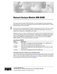
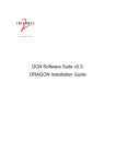
To help you get started using the NAM, refer to this roadmap:
Begin to
install
the NAM
Quick Start Guide
for the
Catalyst 6500 Series
and
Cisco 7600 Series
Network Analysis
Module
Getting Started with the NAM
Information about the NAM
in this release
Quick Setup instructions and
basic configuration
Is the Catalyst 6500
Yes
series switch installed
on your network?
Install and
configure
the NAM
No
Release Notes for
Catalyst 6500 Series
Network Analysis
Module
Software Release
3.1
Catalyst 6500 Series
Network Analysis
Module
Installation and
Configuration Note
Software and hardware
requirements for the NAM
Installing and Removing
the NAM
Configuring the NAM
Catalyst 6500 Series
Network Analysis
Module
Command Reference
Sessioning into the NAM
Setting up the IP address, host,
gateway, domain, name server
and SNMP information
If you need information about
installing the Catalyst 6500
series switch, refer to the
following documentation.
Configure
and use
the NAM
Traffic Analyzer
Starting the web server on the
NAM (which starts the NAM Traffic
Analyzer application) and pointing
your web browser at the NAM you
want to configure.
User Guide for the
Catalyst 6500 Series
Network Analysis
Module Traffic
Analyzer
Administering the NAM
This guide is part of the online help for the Traffic Analyzer.
To access the online help, point your web browser at the
NAM and click on the Help link in the upper right of the screen.
Catalyst 6500
Family
Installation
Guide
Catalyst 6500
Release
Notes
Getting the Latest
Software Information
Software
Configuration
Guide
Troubleshooting the NAM
Quick
Configuration
Guide
Command
Reference
System
Message
Guide
79164
Troubleshooting
Tips
Catalyst 6500 Series Switch and Cisco 7600 Series Router Network Analysis Module Installation and Configuration Note
1-2
78-16413-01
Chapter 1
Overview
Understanding How the NAM Works
This section describes how the Catalyst 6500 series switch, Catalyst 6000 series switch, or Cisco 7600
series router Network Analysis Module (NAM) operates. This section contains these subsections:
•
Understanding How the NAM Uses SPAN, page 1-4
•
Understanding How the NAM Uses VACLs, page 1-4
•
Understanding How the NAM Uses NDE, page 1-5
The NAM monitors and analyzes network traffic using remote monitoring (RMON), RMON extensions
for switched networks (SMON), and other management information bases (MIBs). For more
information, see the “Supported MIB Objects” section on page 5-15.
The NAM monitors, analyzes, and views NetFlow on remote devices and supports these RMON groups:
•
RMON groups defined in RFC 2819
•
RMON2 groups defined in RFC 2021
•
DSMON groups defined in RFC 3287
•
High Capacity RMON groups defined in RFC 3273 (except the media Independent Group)
•
SMON groups defined in RFC 2613
•
All groups defined in the Application Response Time MIB
The NAM can also monitor individual Ethernet VLANs, which allows it to serve as an extension to the
basic RMON support provided by the Catalyst 6500 series supervisor engine.
You can use any other IETF-compliant RMON application to access link, host, protocol, and
response-time statistics for capacity planning, departmental accounting, and real-time application
protocol monitoring. You also can use filters and capture buffers to troubleshoot the network.
The NAM can analyze Ethernet VLAN traffic from the following sources:
•
Ethernet, Fast Ethernet, Gigabit Ethernet, trunk port, or Fast EtherChannel SPAN or RSPAN source
port.
For more information about SPAN and RSPAN, refer to the “Configuring SPAN and RSPAN”
chapter in the Catalyst 6500 Series Switch Software Configuration Guide.
•
NetFlow Data Export (NDE).
For more information about NDE, refer to the Catalyst 6500 Series Switch Software Configuration
Guide.
Table 1-1 summarizes the traffic sources that are used for NAM monitoring.
Table 1-1
Summary of Traffic Sources for NAM Monitoring
Traffic Source
LAN
WAN
Ports
VLANs
Ports
VLANs
VACL capture
Yes
Yes
Yes
N/A
NetFlow Data Export NDE (local)
Yes
Yes
Yes
Yes
NetFlow Data Export NDE (remote) Yes
Yes
Yes
Yes
SPAN
Yes
No
No
Yes
Catalyst 6500 Series Switch and Cisco 7600 Series Router Network Analysis Module Installation and Configuration Note
78-16413-01
1-3
Chapter 1
Overview
Understanding How the NAM Uses SPAN
A switched port analyzer (SPAN) session is an association of a destination port with a set of source ports,
configured with parameters that specify the monitored network traffic. You can configure multiple SPAN
sessions in a switched network.
The WS-SVC-NAM-1 platform provides a single destination port for SPAN sessions. The
WS-SVC-NAM-2 platform provides two possible destination ports for SPAN and VACL sessions.
Multiple SPAN sessions to the NAM are supported, but they must be destined for different ports. The
NAM destination ports for use by the SPAN graphical user interface (GUI) are named DATA PORT 1
and DATA PORT 2 by default. In the CLI, SPAN ports are named as shown in Table 1-2.
Table 1-2
SPAN Port Names
Module
Cisco IOS
Catalyst Operating System
NAM-1
data-port 1
module number:3
NAM-2
data-port 1 and data-port 2
module number:7 or module number:8
Each of these ports is independent. You may create data-port collections that are populated by only the
traffic from one of the ports or collections that can be populated by traffic from both ports. You can still
create VLAN-based collections with packets from either port that match the specified VLAN populating
such collections.
For more information about SPAN and how to configure it on the Catalyst 6000 and 6500 series switches,
use this URL:
http://www.cisco.com/univercd/cc/td/doc/product/lan/cat6000/122sy/swcg/span.htm#1032978
For more information about SPAN and how to configure it on the Cisco 7600 series router, use this URL:
http://www.cisco.com/univercd/cc/td/doc/product/core/cis7600/software/122sx/swcg/span.htm
Understanding How the NAM Uses VACLs
A VLAN access contrl list (VACL) can forward traffic from either a WAN interface or VLANs to a data
port on the NAM. VACLs provide an alternative to using SPAN. VACLs can provide access control based
on Layer 3 addresses for IP and IPX protocols. Unsupported protocols are access controlled through
MAC addresses. MAC VACLs cannot be used to access control IP or IPX addresses.
There are two types of VACLs, one which captures all bridged or routed VLAN packets and another
which captures a selected subset of all bridged or routed VLAN packets. Catalyst operating system
VACLs can only be used to capture VLAN packets because they are initially routed or bridged into the
VLAN on the switch.
VACLs can provide access control for all packets that are bridged within a VLAN or that are routed into
or out of a VLAN or, with Release 12.1(13)E or later releases, a WAN interface. Unlike regular Cisco
IOS standard or extended ACLs that are configured on router interfaces only and are applied on routed
packets only, VACLs apply to all packets and can be applied to any VLAN or WAN interface. VACLs
are processed in the hardware.
VACLs use Cisco IOS access control lists (ACLs). VACLs ignore any Cisco IOS ACL fields that are not
supported in the hardware. Standard and extended Cisco IOS ACLs are used to classify packets.
Classified packets can be subject to a number of features such as access control (security), encryption,
and policy-based routing. Standard and extended Cisco IOS ACLs are only configured on router
interfaces and applied on routed packets.
Catalyst 6500 Series Switch and Cisco 7600 Series Router Network Analysis Module Installation and Configuration Note
1-4
78-16413-01
Chapter 1
Overview
Once a VACL is configured on a VLAN, all packets (routed or bridged) entering the VLAN are checked
against the VACL. Packets can either enter the VLAN through a switch port or through a router port after
being routed. Unlike Cisco IOS ACLs, VACLs are not defined by direction (input or output).
A VACL contains an ordered list of access control entries (ACEs). Each ACE contains a number of fields
that are matched against the contents of a packet. Each field can have an associated bit mask to indicate
which bits are relevant. Each ACE is associated with an action that describes what the system should do
with the packet when a match occurs. The action is feature dependent. Catalyst 6000 and 6500 series
switches and Cisco 7600 series routers support three types of ACEs in the hardware: IP, IPX, and
MAC-Layer traffic. The VACLs that are applied to WAN interfaces support only IP traffic.
When you configure a VACL and apply it to a VLAN, all packets entering the VLAN are checked against
this VACL. If you apply a VACL to the VLAN and an ACL to a routed interface in the VLAN, a packet
coming in to the VLAN is first checked against the VACL and, if permitted, is then checked against the
input ACL before it is handled by the routed interface. When the packet is routed to another VLAN, it
is first checked against the output ACL applied to the routed interface and, if permitted, the VACL
configured for the destination VLAN is applied. If a VACL is configured for a packet type and a packet
of that type does not match the VACL, the default action is deny.
When configuring VACLs note the following:
•
VACLs and context-based access control (CBAC) cannot be configured on the same interface
•
TCP Intercepts and Reflexive ACLs take precedence over a VACL action on the same interface.
•
IGMP packets are not checked against VACLs.
For details on how to configure VACL with Cisco IOS software, refer to the Network Analysis Module
for Catalyst 6500 Series and Cisco 7600 Series Command Reference. For details on how to configure
security ACLs with the Catalyst operating system, refer to the Catalyst 6500 Series Software
Configuration Guide and the Catalyst 6500 Series Command Reference.
Understanding How the NAM Uses NDE
NetFlow Data Export (NDE) is a remote device that allows you to monitor port traffic on the NAM. To
use an NDE data source for the NAM, you must configure the remote device to export the NDE packets
to UDP port 3000 on the NAM. You may need to configure the device on a per-interface basis. A screen
has been added to the web application user interface for specifying NDE devices (an NDE device is
identified by its IP address). By default, the switch’s local supervisor engine is always available as an
NDE device.
You can define additional NDE devices by specifying the IP addresses and (optionally) the community
strings. Community strings are used to upload convenient textual strings for interfaces on the remote
devices that are monitored in NetFlow records.
For more information about the NDE data sources of the NAM, go to the NAM Traffic Analyzer online
help menu and choose the Contents > Setting Up the Application > Setting Up Data Sources >
Understanding NetFlow Interfaces.
Managing the NAM
You can manage the NAM from the embedded web-based NAM Traffic Analyzer application (directing
a web browser to the NAM) or a Simple Network Management Protocol (SNMP) management
application, such as those bundled with CiscoWorks2000.
Catalyst 6500 Series Switch and Cisco 7600 Series Router Network Analysis Module Installation and Configuration Note
78-16413-01
1-5
Chapter 1
Overview
NAM Traffic Analyzer provides access to the management and monitoring features for NAM data and
voice traffic through a web browser. To use NAM Traffic Analyzer, you need to do some basic
configuration tasks on the NAM using the CLI. You then can start NAM Traffic Analyzer with a single
command.
With NAM Traffic Analyzer, you can do the following tasks:
•
Configure and view historical reports about various traffic statistics
•
Configure SPAN resources
•
Configure collections
•
Monitor statistics
•
Capture and decode packets
•
Set and view alarms
For added security, you can use NAM Traffic Analyzer to configure the NAM to use a remote TACACS+
server. A TACACS+ server provides authentication and authorization for your web-based users. You also
can use a local database on the NAM for security.
You also can manage the NAM using an SNMP management application such as the Cisco NetScout
nGenius Real-Time Monitor (RTM), which is a component of CiscoWorks2000 LAN management
solutions (NMS). For more information about using RTM, refer to the CiscoWorks documentation or this
URL:
http://www.Cisco.com/univercd/cc/td/doc/product/lan/cat6000/fam_mod/rel2_1_2/ol_2428.htm
To use RMON and SNMP agent support, you configure the NAM using the CLI.
If you have a NAM that is already configured and running in the switch, and you are familiar with the
NAM, you can begin using NAM Traffic Analyzer by entering the ip http server enable CLI command
and then starting NAM Traffic Analyzer in your browser.
Refer to the User Guide for the Network Analysis Module Traffic Analyzer Release 3.3 for more
information about using NAM Traffic Analyzer.
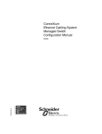
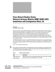
Front Panel Description
The NAM front panel (see Figure 1-1) includes a STATUS LED and SHUTDOWN button.
Figure 1-1
Network Analysis Module
NETWORK ANALYSIS MODULE
STATUS LED
SHUTDOWN
73753
ST
AT
U
S
WS-SVC-NAM-2
SHUTDOWN button
Catalyst 6500 Series Switch and Cisco 7600 Series Router Network Analysis Module Installation and Configuration Note
1-6
78-16413-01
Chapter 1
Overview
STATUS LED
The STATUS LED indicates the operating states of the NAM. Table 1-3 describes the LED operation.
Table 1-3
STATUS LED Description
Color
Description
Green
All diagnostic tests pass. The NAM is operational.
Red
A diagnostic other than an individual port test failed.
Orange
Indicates one of three conditions:
• The NAM is running through its boot and self-test diagnostic sequence.
Off
•
The NAM is disabled.
•
The NAM is in the shutdown state.
The NAM power is off.
SHUTDOWN Button
Caution
Do not remove the NAM from the switch until the NAM has shut down completely and the STATUS
LED is orange. You risk disk corruption if you remove the NAM from the switch before the NAM
completely shuts down.
To avoid corrupting the NAM hard disk, you must correctly shut down the NAM before you remove it
from the chassis or disconnect the power. This shutdown procedure is normally initiated by commands
entered at the supervisor engine CLI prompt or the NAM CLI prompt.
Note
If disk corruption occurs, you can recover the disk by reupgrading the application image with the
--install option. See “Upgrading the NAM Application Software with Catalyst Operating System
Software” section on page 4-17.
If the NAM fails to respond to these commands properly, press the SHUTDOWN button on the front
panel to initiate the shutdown procedure.
The shutdown procedure may require several minutes. The STATUS LED turns off when the NAM shuts
down.
Catalyst 6500 Series Switch and Cisco 7600 Series Router Network Analysis Module Installation and Configuration Note
78-16413-01
1-7
Chapter 1
Overview
Specifications
Table 1-4 describes the specifications for the NAM.
Table 1-4
WS-SVC-NAM-1 and WS-SVC-NAM-2 Specifications
Specification
Description
Dimensions (H x W x D)
1.2 x 14.4 x 16 in. (3.0 x 35.6 x 40.6 cm)
Weight
Minimum: 3 lb (1.36 kg)
Maximum: 5 lb (2.27 kg)
Environmental conditions:
Operating temperature
32 to 104° F (0 to 40° C)
Nonoperating temperature
–40 to 158° F (–40 to 70° C)
Humidity
10 to 90%, noncondensing
Humidity—Ambient
(Noncondensing) Nonoperating and
Storage
5 to 95%
Altitude
Sea level to 10,000 ft (3050 m)
Catalyst 6500 Series Switch and Cisco 7600 Series Router Network Analysis Module Installation and Configuration Note
1-8
78-16413-01
C H A P T E R
2
Installing the Network Analysis Module
This chapter describes the software and hardware requirements to support the Catalyst 6500 series
switch, Catalyst 6000 series switch, or Cisco 7600 series router NAM, and how to install and remove the
NAM. This chapter contains these sections:
•
Software Requirements, page 2-2
•
Hardware Requirements, page 2-2
•
Required Tools, page 2-3
•
Installing and Removing the NAM, page 2-3
Catalyst 6500 Series Switch and Cisco 7600 Series Router Network Analysis Module Installation and Configuration Note
78-16413-01
2-1
Chapter 2
Installing the Network Analysis Module
Software Requirements
Software Requirements
Note
Starting with maintenance image release 2.1(1), there is a single maintenance image for services
modules. Refer to this URL:
http://www.cisco.com/cgi-bin/tablebuild.pl/cat6000-serv-maint
Table 2-1 lists the NAM software versions that are supported by the Catalyst operating system and
Cisco IOS software.
Table 2-1
NAM Software Compatibility
Module
Application
Image
Maintenance
Image
Catalyst Operating
System Software
3.3(1)
1.1(1)m
Release 7.3(1) or later
with Supervisor
Engine 1A or 2
WS-SVC-NAM-1
WS-SVC-NAM-2
2.1(1)
Cisco IOS Software
Release 12.1(13)E1
or later with a
Supervisor Engine 2
with an MSFC2
Release 12.1(19E)1
or later with a
Supervisor Engine
1A with an MSFC2
Supported
Browsers
Netscape 7 or 7.1
on Windows 2000
and Solaris
Internet Explorer
5.0 and later on
Windows 2000
Release 12.2(14)SX1
with a WS-SUP720
Release 8.2(1) or later
with a WS-SUP720
1. If you are running a 12.1(13)E-based release, we recommend that you use a later 13E release, for example, use Release 12.1(13)E11 over 12.1(13)E3.
Hardware Requirements
Table 2-2 lists the NAM hardware versions that are supported by the Catalyst operating system and
Cisco IOS software.
Table 2-2
NAM Hardware Compatibility
Module
Catalyst Operating System Software
Cisco IOS Software
WS-SVC-NAM-1
WS-SVC-NAM-2
Supervisor Engine 1A or 2 or
WS-SUP720
Supervisor Engine 2 with an MSFC2 or
WS-SUP720
Catalyst 6500 Series Switch and Cisco 7600 Series Router Network Analysis Module Installation and Configuration Note
2-2
78-16413-01
Chapter 2
Installing the Network Analysis Module
Required Tools
Required Tools
Before installing the NAM, you must install the Catalyst 6500 series switch chassis, Catalyst 6000 series
switch chassis, or Cisco 7600 series router chassis, and at least one supervisor engine. For information
on installing the switch chassis, refer to the chassis installation guide.
Note
These tools are required to install the NAM in the Catalyst 6500 series switch, Catalyst 6000 series
switch, or Cisco 7600 series routers:
•
Flat-blade screwdriver
•
Phillips-head screwdriver
•
Wrist strap or other grounding device
•
Antistatic mat or antistatic foam
Whenever you handle the NAM, always use a wrist strap or other grounding device to prevent
electrostatic discharge (ESD).
Installing and Removing the NAM
During this procedure, wear grounding wrist straps to avoid ESD damage to the card. Do not directly
touch the backplane with your hand or any metal tool, or you could shock yourself.
Warning
All the Catalyst 6500 series switch, Catalyst 6000 series switch, or Cisco 7600 series routers support hot
swapping, which allows you to install, remove, replace, and rearrange modules without turning off the
system power. For more information, see the “Removing a Module” section on page 2-4.
Caution
We recommend that you shut down the NAM before you remove the module.
When the system detects that a module has been installed or removed, the system automatically runs
diagnostic and discovery routines, acknowledges the presence or absence of the module, and resumes
system operation.
To install and use the NAM, you need to complete the following actions:
•
Perform the initial installation by placing the NAM in a switch.
•
At the switch CLI, session to the NAM CLI and provide a basic configuration.
•
Send a data source to the NAM (NetFlow data, switch port analyzer [SPAN] ports, VLANs, or
EtherChannels).
•
Configure collection types that you want to monitor (RMON, voice, application response time, and
other collection monitoring as required for your network).
•
Configure alarms.
•
View monitored statistics, alarms, and use packet capture or decode functionality.
Catalyst 6500 Series Switch and Cisco 7600 Series Router Network Analysis Module Installation and Configuration Note
78-16413-01
2-3
Chapter 2
Installing the Network Analysis Module
Installing and Removing the NAM
This section describes how to install and verify the operation of the NAM in the Catalyst 6500 series
switch, Catalyst 6000 series switch, and Cisco 7600 series router and contains the following sections:
•
Slot Assignments, page 2-4
•
Removing a Module, page 2-4
•
Installing a Module, page 2-5
•
Verifying the Installation, page 2-12
Slot Assignments
The Catalyst 6006 and 6506 switch chassis have 6 slots, the Catalyst 6009 and 6509 switch chassis have
9 slots, and the Catalyst 6513 switch chassis has 13 slots. The module can occupy any slot in the
Catalyst 6500 series switch, and Catalyst 6000 series switch or Cisco 7600 series router that is not
occupied by a supervisor engine.
Note
The Catalyst 6509-NEB switch has vertical slots numbered 1 to 9 from right to left. Install the modules
with the component side facing to the right.
Make sure that you install switching-module filler plates, which are blank switching-module carriers, in
the empty slots to maintain consistent airflow through the switch chassis.
Removing a Module
This section describes how to remove an existing module from a chassis slot.
Caution
During this procedure, wear grounding wrist straps to avoid ESD damage to the card. Do not directly
touch the backplane with your hand or any metal tool, or you could shock yourself.
Warning
Invisible laser radiation may be emitted from disconnected fibers or connectors. Do not stare into
beams or view directly with optical instruments.
To remove a supervisor engine or module from the chassis, perform these steps:
Step 1
Disconnect any network interface cables attached to the supervisor engine or module.
Note
Step 2
The NAM does not have any interface cable connections.
Verify that the captive installation screws on all of the modules in the chassis are tight.
This action ensures that the space created by the removed module is maintained.
Note
If the captive installation screws are loose, the electromagnetic interference (EMI) gaskets on
the installed modules will push the modules toward the open slot, reducing the opening size and
making it difficult to install the replacement module.
Catalyst 6500 Series Switch and Cisco 7600 Series Router Network Analysis Module Installation and Configuration Note
2-4
78-16413-01
Chapter 2
Installing the Network Analysis Module
Installing and Removing the NAM
Step 3
Loosen the two captive installation screws on the supervisor engine or module.
Step 4
Depending on the orientation of the slots in the chassis (horizontal or vertical), perform one of the
following sets of steps:
Horizontal slots
a.
Place your thumbs on the left and right ejector levers, and simultaneously rotate the levers outward
to unseat the module from the backplane connector.
b.
Grasp the front edge of the module and slide the module part of the way out of the slot. Place your
other hand under the module to support the weight of the module. Do not touch the module circuitry.
Vertical slots
a.
Place your thumbs on the ejector levers located at the top and bottom of the module, and
simultaneously rotate the levers outward to unseat the module from the backplane connector.
b.
Grasp the edges of the module, and slide the module straight out of the slot. Do not touch the module
circuitry.
Step 5
Place the module on an antistatic mat or antistatic foam, or immediately reinstall it in another slot.
Step 6
If the slot is to remain empty, install a module filler plate to keep dust out of the chassis and to maintain
proper airflow through the chassis.
Warning
Blank faceplates (filler panels) serve three important functions: they prevent exposure to hazardous
voltages and currents inside the chassis; they contain electromagnetic interference (EMI) that might
disrupt other equipment; and they direct the flow of cooling air through the chassis. Do not operate
the system unless all cards and faceplates are in place.
Installing a Module
This section describes how to install modules in the Catalyst 6500 series switch, Catalyst 6000 series
switch, or Cisco 7600 series router.
Caution
To prevent ESD damage, handle modules by the carrier edges only.
Caution
During this procedure, wear grounding wrist straps to avoid ESD damage to the card. Do not directly
touch the backplane with your hand or any metal tool, or you could shock yourself.
Warning
Invisible laser radiation may be emitted from disconnected fibers or connectors. Do not stare into
beams or view directly with optical instruments.
Catalyst 6500 Series Switch and Cisco 7600 Series Router Network Analysis Module Installation and Configuration Note
78-16413-01
2-5
Chapter 2
Installing the Network Analysis Module
Installing and Removing the NAM
To install a supervisor engine or module in the chassis, perform these steps:
Step 1
Choose a slot for the supervisor engine or module.
Step 2
Verify that there is enough clearance to accommodate any interface equipment that you will connect
directly to the supervisor engine or module ports. If possible, place modules between empty slots that
contain only module filler plates.
Step 3
Verify that the captive installation screws are tightened on all modules installed in the chassis.
This action ensures that the EMI gaskets on all modules are fully compressed in order to maximize the
opening space for the new module or the replacement module.
Note
Step 4
If the captive installation screws are loose, the EMI gaskets on the installed modules will push
adjacent modules toward the open slot, reducing the opening size and making it difficult to
install the replacement module.
Remove the module filler plate by removing the two Phillips pan-head screws from the filler plate.
To remove a module, refer to the “Removing a Module” section on page 2-4.
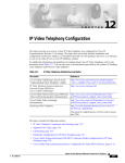
Step 5
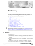
Fully open both ejector levers on the new or replacement module. (See Figure 2-1.)
Catalyst 6500 Series Switch and Cisco 7600 Series Router Network Analysis Module Installation and Configuration Note
2-6
78-16413-01
Chapter 2
Installing the Network Analysis Module
Installing and Removing the NAM
Figure 2-1
Positioning the Module in a Horizontal Slot Chassis
Insert module
between slot guides
EMI gasket
3
4
5
6
4
5
6
WS-X6K-SUP2-2GE
1
ST
AT
US
SY
ST
OL
EM
T
E
NS
CO
R
M
PW
GM
SE
Switch
100%
T
Load
CONSOLE
PORT
MODE
RE
PORT 1
PORT 2
CONSOLE
SUPERVISOR2
PCMCIA
EJECT
1%
WS-X6K-SUP2-2GE
2
ST
AT
US
SY
ST
OL
EM
CO
T
E
NS
R
PW
M
GM
SE
Switch
100%
T
Load
CONSOLE
PORT
MODE
RE
PORT 1
PORT 2
CONSOLE
SUPERVISOR2
PCMCIA
EJECT
1%
3
4
FAN
STATUS 5
6
WS-X6224
AT
US
AC
TI
VE
SE
LE
24 PORT 100FX
NE
EMI gasket
CT
XT
58569
ST
o
o
INPUT
OK
FAN
OK
OUTPUT
FAIL
INPUT
OK
FAN
OK
OUTPUT
FAIL
WS-C6500-SFM
US
AT
ST
E
TIV
AC
SWITCH FABRIC MDL
Ejector lever fully
extended
Catalyst 6500 Series Switch and Cisco 7600 Series Router Network Analysis Module Installation and Configuration Note
78-16413-01
2-7
Chapter 2
Installing the Network Analysis Module
Installing and Removing the NAM
Step 6
Depending on the orientation of the slots in the chassis (horizontal or vertical), perform one of these
sets of steps:
Horizontal slots
a.
Position the supervisor engine or module in the slot. (See Figure 2-1.) Make sure that you align the
sides of the module carrier with the slot guides on each side of the slot.
b.
Carefully slide the supervisor engine or module into the slot until the EMI gasket along the top edge
of the module makes contact with the module in the slot above it and both ejector levers have closed
to approximately 45 degrees in relation to the module faceplate. (See Figure 2-2.)
Figure 2-2
Clearing the EMI Gasket in a Horizontal Slot Chassis
WS-X6K-SUP2-2GE
1
ST
AT
US
SY
ST
EM
CO
NS
O
LE
PW
R
M
G
M
T
RE
SE
Switch
100%
T
CONSOLE
Load
CONSOLE
PORT
MODE
SUPERVISOR2
PORT 1
PCMCIA
PORT 2
EJECT
1%
WS-X6K-SUP2-2GE
LI
2
ST
AT
US
SY
ST
EM
CO
NS
O
LE
PW
R
M
G
M
LI
NK
T
RE
SE
Switch
100%
T
CONSOLE
SUPERVISOR2
NK
CONSOLE
PORT
MODE
Load
PORT 1
PCMCIA
PORT 2
EJECT
1%
LI
NK
LI
NK
3
Press down
4
FAN
STATUS 5
Press down
WS-X6224
S
TU
STA
VE
TI
AC
24 PORT 100FX
CT
LE
SE
XT
NE
6
3
4
WS-C6500-SFM
5
5
SWITCH FABIR
6
c.
Caution
US
AT
ST
D MDL
E
TIV
AC
1 mm Gap between the module
EMI gasket and the
module above it
6
58570
4
Using the thumb and forefinger of each hand, grasp the two ejector levers and press down to create
a small (0.040 inch [1 mm]) gap between the module’s EMI gasket and the module above it. (See
Figure 2-2.)
Do not press down too hard on the levers because they can bend and get damaged.
d.
While pressing down, simultaneously close the left and right ejector levers to fully seat the
supervisor engine or module in the backplane connector. The ejector levers are fully closed when
they are flush with the module faceplate. (See Figure 2-3.)
Catalyst 6500 Series Switch and Cisco 7600 Series Router Network Analysis Module Installation and Configuration Note
2-8
78-16413-01
Chapter 2
Installing the Network Analysis Module
Installing and Removing the NAM
Figure 2-3
Ejector Lever Closure in a Horizontal Slot Chassis
WS-X6K-SUP2-2GE
1
ST
AT
US
SY
ST
EM
CO
NS
O
LE
PW
R
M
G
M
T
RE
SE
Switch
100%
T
CONSOLE
SUPERVISOR2
Load
CONSOLE
PORT
MODE
PORT 1
PCMCIA
PORT 2
EJECT
1%
WS-X6K-SUP2-2GE
LI
2
ST
AT
US
SY
ST
EM
CO
NS
O
LE
PW
R
M
G
M
NK
LI
NK
T
RE
SE
Switch
100%
T
CONSOLE
SUPERVISOR2
Load
CONSOLE
PORT
MODE
PORT 1
PCMCIA
PORT 2
EJECT
1%
LI
NK
LI
NK
3
4
FAN
STATUS 5
WS-C6500-SFM
S
TU
STA
SWITCH FABRIC MDL
VE
TI
AC
CT
LE
SE
XT
NE
58571
6
Ejector levers flush
with module faceplate
Note
e.
Failure to fully seat the module in the backplane connector can result in error messages.
Tighten the two captive installation screws on the supervisor engine or module.
Note
Make sure that the ejector levers are fully closed before tightening the captive installation
screws.
Vertical slots
a.
Position the supervisor engine or switching module in the slot. (See Figure 2-4.) Make sure that you
align the sides of the switching module carrier with the slot guides on the top and bottom of the slot.
Catalyst 6500 Series Switch and Cisco 7600 Series Router Network Analysis Module Installation and Configuration Note
78-16413-01
2-9
Chapter 2
Installing the Network Analysis Module
Installing and Removing the NAM
Figure 2-4
Positioning the Module in a Vertical Slot Chassis
Ejector lever fully
extended
WS-C6500-SFM
SWITCH FABRIC MDL
FAN
STATUS
WS-X6K-SUP2-2GE
MT
OLE MG
TEM NS
TUS
R
SET
RE
PW
SYS
CO
STA
MT
E
M
S
OL
T
MG
TU
R
NS
SE
STE
RE
PW
CO
SY
STA
WS-X6K-SUP2-2GE
SUPERVISOR2
SUPERVISOR2
ST
AT
CONSOLE
CONSOLE
AC
US
PORT
CONSOLE
PORT
MODE
MODE
WS-X6224
24 PORT 100FX
CONSOLE
TIV
E
US
AT
ST
E
TIV
AC
PCMCIA
PCMCIA
EJECT
EJECT
Switch
Switch
1%
100%
1%
100%
Load
Load
PORT 1
PORT 1
XT
SE
LE
PORT 2
PORT 2
NE
EMI
gasket
CT
63585
EMI
gasket
o
o
INPUT
OK
FAN
OK
OUTPUT
FAIL
INPUT
OK
FAN
OK
OUTPUT
FAIL
6
Insert module
between slot guides
3
4
b.
Carefully slide the supervisor engine or module into the slot until the EMI gasket along the right
edge of the module makes contact with the module in the slot adjacent to it and both ejector levers
have closed to approximately 45 degrees with respect to the module faceplate. (See Figure 2-5.)
c.
Using the thumb and forefinger of each hand, grasp the two ejector levers and exert a slight pressure
to the left, moving the module approximately 0.040 inches (1 mm) to create a small gap between the
module’s EMI gasket and the module adjacent to it. (See Figure 2-5.)
Catalyst 6500 Series Switch and Cisco 7600 Series Router Network Analysis Module Installation and Configuration Note
2-10
78-16413-01
Chapter 2
Installing the Network Analysis Module
Installing and Removing the NAM
Figure 2-5
Clearing the EMI Gasket in a Vertical Slot Chassis
Gap between the module
EMI gasket and the
module above it
1 mm
WS-C6500-SFM
SWITCH FABIRD MDL
US
AT
ST
E
TIV
AC
FAN
STATUS
WS-X6K-SUP2-2GE
MT
E
M
S
OL
T
MG
TU
R
NS
SE
STE
RE
PW
CO
SY
STA
US
AT
ST
MT
OLE MG
TEM NS
TUS
R
SET
RE
PW
SYS
CO
STA
WS-X6K-SUP2-2GE
SUPERVISOR2
SUPERVISOR2
WS-X6224
24 PORT 100FX
CONSOLE
CONSOLE
E
TIV
AC
PORT
MODE
PORT
MODE
CONSOLE
CONSOLE
Press left
PCMCIA
PCMCIA
EJECT
EJECT
Switch
Switch
1%
100%
1%
100%
Load
Load
NE
XT
PORT 1
PORT 1
Press left
SE
LE
CT
63586
PORT 2
PORT 2
o
o
INPUT
OK
FAN
OK
OUTPUT
FAIL
INPUT
OK
Caution
FAN
OK
OUTPUT
FAIL
Do not press down too hard on the levers because they can bend and get damaged.
d.
While pressing on the ejector levers, simultaneously close them to fully seat the supervisor engine
or module in the backplane connector. The ejector levers are fully closed when they are flush with
the module faceplate. (See Figure 2-6.)
Catalyst 6500 Series Switch and Cisco 7600 Series Router Network Analysis Module Installation and Configuration Note
78-16413-01
2-11
Chapter 2
Installing the Network Analysis Module
Installing and Removing the NAM
Figure 2-6
Ejector Lever Closure in a Vertical Slot Chassis
FAN
STATUS
US
SY
ST
CO
EM
T
M
LE
G
O
T
M
EM
US
R
NS
SE
ST
AT
RE
PW
SY
CO
ST
AT
NS
O
PW
LE
STA
R
M
RE
G
S
M
TU
SE
T
T
AC
CONSOLE
VE
CONSOLE
TI
CONSOLE
PORT
MODE
CONSOLE
PORT
MODE
PCMCIA
PCMCIA
EJECT
EJECT
100%
Switch
Switch
1%
1%
100%
LE
PORT 1
PORT 1
SE
Load
Load
XT
WS-X6K-SUP2-2GE
SUPERVISOR2
ST
WS-X6K-SUP2-2GE
SUPERVISOR2
WS-X6224
24 PORT 100FX
NE
CT
63587
PORT 2
PORT 2
All ejector levers flush
with module faceplate
e.
Tighten the two captive installation screws on the module.
Note
Make sure that the ejector levers are fully closed before tightening the captive installation
screws.
Verifying the Installation
This section describes how to verify the NAM installation.
Cisco IOS Software
To verify that the system acknowledges the new module and has brought it online, enter the show
module [mod-num | all] command.
This example shows the output of the show module command:
Router# show module
Mod Slot Ports Module-Type
--- ---- ----- ------------------------1
1
2
1000BaseX Supervisor
15 1
1
Multilayer Switch Feature
2
2
3
Network Analysis Module
Router#
Model
------------------WS-X6K-S2U-MSFC2
WS-F6K-MSFC2
WS-SVC-NAM-1
Sub
--yes
no
no
Status
-------ok
ok
ok
Catalyst 6500 Series Switch and Cisco 7600 Series Router Network Analysis Module Installation and Configuration Note
2-12
78-16413-01
Chapter 2
Installing the Network Analysis Module
Installing and Removing the NAM
When the NAM initially boots, by default it runs a partial memory test. To perform a full memory test,
enter the hw-module module slot_number reset device:partition mem-test-full command. This
command is specific to Cisco IOS software and is not available in Catalyst operating system software.
A full memory test takes more time to complete than a partial memory test depending on the memory
size.
You also can use the hw-module module slot_number mem-test-full command in a Cisco IOS system.
This example shows how to do a full memory test for module 5:
Router(config)# hw-module module 5 mem-test-full
Catalyst Operating System Software
To verify that the switch acknowledges the new NAM and has brought it online, enter the show module
or show port [mod/port] command.
This example shows the output of the show module command:
Console>
Mod Slot
--- ---1
1
15 1
3
3
5
5
.
Console>
(enable) show module
Ports Module-Type
----- ------------------------2
1000BaseX Supervisor
1
Multilayer Switch Feature
2
Network Analysis Module
48
10/100BaseTX Ethernet
Model
------------------WS-X6K-SUP1A-2GE
WS-F6K-MSFC
WS-SVC-NAM-1
WS-X6248-RJ-45
Sub
--yes
no
no
no
Status
-------ok
ok
ok
ok
(enable)
When the NAM initially boots, by default it runs a partial memory test. For Catalyst operating system
software, you can perform a full memory test when you enter the set boot device bootseq mod#
mem-test-full command. This command is specific to Catalyst operating system software and is not
available in Cisco IOS software. This example shows how to do a full memory test:
Console (enable) set boot device cf:1 4 mem-test-full
Device BOOT variable = cf:1
Memory-test set to FULL
Warning:Device list is not verified but still set in the boot string.
Note
When specifying the boot device for the WS-SVC-NAM-1 and the WS-SVC-NAM-2, you must use
hdd:1 for the application image and cf:1 for the maintenance image.
Console> (enable) show boot device 4
Device BOOT variable = cf:1
Memory-test set to FULL
When you next reset the NAM, the full memory test runs. A full memory test takes more time to complete
than a partial memory test.
This example shows how to reset the partial memory test:
Console> (enable) set boot device cf:1 4
Device BOOT variable = cf:1
Memory-test set to PARTIAL
Warning:Device list is not verified but still set in the boot string.
Console> (enable)
Console> (enable) show boot device 4
Device BOOT variable = cf:1
Memory-test set to PARTIAL
Catalyst 6500 Series Switch and Cisco 7600 Series Router Network Analysis Module Installation and Configuration Note
78-16413-01
2-13
Chapter 2
Installing the Network Analysis Module
Installing and Removing the NAM
Catalyst 6500 Series Switch and Cisco 7600 Series Router Network Analysis Module Installation and Configuration Note
2-14
78-16413-01
C H A P T E R
3
Getting Started
This chapter describes how to configure the Catalyst 6500 series switch, Catalyst 6000 series switch, and
Cisco 7600 series router NAM and includes these sections:
•
Configuring the NAM, page 3-1
•
Configuring Traffic Sources for Capturing NAM Traffic, page 3-1
•
Operating-System-Independent Configuration, page 3-12
Configuring the NAM
How you configure the NAM on your switch depends on whether you are using Cisco IOS software or
the Catalyst operating system software. Several NAM configuration tasks are common to both switch
operating systems.
For initial configuration of the NAM. refer to the Quick Start Guide for the Catalyst 6500 Series and
Cisco 7600 Series Network Analysis Module.
After you set up the NAM initial configuration, you can configure VLAN access control lists (VACLs),
either local or remote NetFlow Data Export (NDE), and the switched port analyzer (SPAN) to monitor
network traffic. For more information, see the “Configuring Traffic Sources for Capturing NAM Traffic”
section on page 3-1.
When you complete configuring the software-dependent attributes for the NAM, you can configure the
software-independent attributes. For more information, see the “Operating-System-Independent
Configuration” section on page 12.
Configuring Traffic Sources for Capturing NAM Traffic
The WS-SVC-NAM-1 platform provides a single destination port for SPAN sessions.
The WS-SVC-NAM-2 platform provides two possible destination ports for VACL and SPAN sessions.
The destination ports for use by the SPAN GUI are named DATA PORT 1 and DATA PORT 2 by default.
For the CLI SPAN port names, refer to Table 1-2 on page 1-4.
VACL and SPAN cannot be applied to the same port simultaneously. Table 3-1 shows the SPAN and
VACL port configurations that are supported on the NAM.
Catalyst 6500 Series Switch and Cisco 7600 Series Router Network Analysis Module Installation and Configuration Note
78-16413-01
3-1
Chapter 3
Getting Started
Configuring Traffic Sources for Capturing NAM Traffic
Table 3-1
NAM SPAN and VACL Port Configurations
NAM-1
NAM-2
One SPAN session only
Two SPAN sessions
One VACL session only
One SPAN session and one VACL session
Two VACL sessions
For more information about SPAN, see these URLs:
http://www.cisco.com/univercd/cc/td/doc/product/lan/cat6000/122sx/swcg/span.htm
http://www.cisco.com/univercd/cc/td/doc/product/lan/cat6000/sw_8_2/confg_gd/span.htm
For more information about VACL, see these URLs:
http://www.cisco.com/univercd/cc/td/doc/product/lan/cat6000/122sx/swcg/vacl.htm
http://www.cisco.com/univercd/cc/td/doc/product/lan/cat6000/sw_82/confg_gd/acc_list.htm#1053650
For more information about NDE, see these URLs:
http://www.cisco.com/univercd/cc/td/doc/product/lan/cat6000/122sx/swcg/nde.htm#1035105
http://www.cisco.com/univercd/cc/td/doc/product/lan/cat6000/sw_8_2/confg_gd/nde.htm
These sections describe how to configure VACLs, either local or remote NDE, and SPAN to monitor
network traffic with the NAM:
•
Cisco IOS Software, page 3-2
•
Catalyst Operating System Software, page 3-8
Cisco IOS Software
You can capture traffic for NAM monitoring from a single VLAN or from multiple VLANs. If you want
to monitor traffic from specific VLANs only, you need to clear the VLANs that you do not want to
monitor from the capture feature.
Using SPAN as a Traffic Source
You can configure SPAN as a traffic source using both the CLI and the NAM Traffic Analyzer
application.
The NAM can analyze Ethernet traffic from Ethernet, Fast Ethernet, Gigabit Ethernet, trunk port, or Fast
EtherChannel SPAN source ports. You can also specify an Ethernet VLAN as the SPAN source.
For more information on SPAN, refer to the Catalyst 6500 Series Switch Cisco IOS Software
Configuration Guide at this URL:
http://www.cisco.com/univercd/cc/td/doc/product/lan/cat6000/index.htm
You cannot use ports on the NAM module as SPAN source ports.
Catalyst 6500 Series Switch and Cisco 7600 Series Router Network Analysis Module Installation and Configuration Note
3-2
78-16413-01
Chapter 3
Getting Started
Configuring Traffic Sources for Capturing NAM Traffic
To enable SPAN on the NAM, perform one of these tasks:
Command
Purpose
Router (config)# monitor session {session_number}
{source {interface type slot/port} | {vlan vlan_ID}}
[, | - | rx | tx | both]
Sets the source interfaces and
VLANs for the monitor session.
Router (config)# monitor session {session_number}
{destination analysis module NAM module number
data-port port}
Enables port 1 of the NAM as a
SPAN destination.
Router (config)# no monitor session session_number
Disables the monitor session.
Router (config)# monitor session {session_number}
{filter {vlan_ID} [, | - ]}
Filters the SPAN session so that only
certain VLANs are seen from switch
port trunks.
Router # show monitor session {session_number}
Shows current monitor sessions.
This example shows how to enable SPAN on the NAM:
Router# show monitor
Session 1
--------Source Ports:
RX Only:
None
TX Only:
None
Both:
None
Source VLANs:
RX Only:
None
TX Only:
None
Both:
None
Destination Ports:None
Filter VLANs:
None
Session 2
--------Source Ports:
RX Only:
None
TX Only:
None
Both:
None
Source VLANs:
RX Only:
None
TX Only:
None
Both:
None
Destination Ports:None
Filter VLANs:
None
Router# configure terminal
Enter configuration commands, one per line.
End with CNTL/Z.
Router(config)# monitor session 1 source vlan 1 both
Note
If you are using the switch CLI to configure SPAN as a traffic source to NAM-1, the SPAN destination
port for NAM-1 is data-port 1. The SPAN destination ports for NAM-2 is data-port 1 and data-port 2.
Catalyst 6500 Series Switch and Cisco 7600 Series Router Network Analysis Module Installation and Configuration Note
78-16413-01
3-3
Chapter 3
Getting Started
Configuring Traffic Sources for Capturing NAM Traffic
Router#
00:21:10:%SYS-5-CONFIG_I:Configured from console by console
Router# conf t
Enter configuration commands, one per line. End with CNTL/Z.
Router(config)# monitor session 1 destination analysis-module 8 data-port 1
Router# show monitor
Session 1
--------Type
:Local Session
Source Ports:
RX Only:
None
TX Only:
None
Both:
None
Source VLANs:
RX Only:
None
TX Only:
None
Both:
1
Source RSPAN VLAN:None
Destination Ports:analysis-module 8 data-port 1
Filter VLANs:
None
Dest RSPAN VLAN: None
Session 2
--------Type
:Local Session
Source Ports:
RX Only:
None
TX Only:
None
Both:
None
Source VLANs:
RX Only:
None
TX Only:
None
Both:
None
Source RSPAN VLAN:None
Destination Ports:None
Filter VLANs:
None
Dest RSPAN VLAN: None
Using a VACL as a Traffic Source
This section describes how to configure a VACL for a switch running Cisco IOS Release 12.1(13)E1 or
later releases. To configure a LAN VACL on the Catalyst operating system, you can use the security ACL
feature to achieve the same result. For more information, see the “Operating-System-Independent
Configuration” procedure on page 3-12.
Configuring a VACL on a WAN Interface
Because WAN interfaces do not support SPAN if you want to monitor traffic on a WAN interface using
a NAM, you need to manually configure a VACL on the switch using the switch CLI. This feature only
works for IP traffic over the WAN interface. You can apply additional filtering rules to target specific
data flows.
In addition, you can use a VACL if there are no available SPAN sessions to direct traffic to the NAM. In
this scenario, you can set up a VACL instead of SPAN for monitoring VLAN traffic.
The following examples describe the steps to configure a VACL for a switch running Cisco IOS
Release 12.1(13)E1 or higher. To configure a LAN VACL on a switch running the Catalyst operating
system, use the ACL feature to achieve the same result.
Catalyst 6500 Series Switch and Cisco 7600 Series Router Network Analysis Module Installation and Configuration Note
3-4
78-16413-01
Chapter 3
Getting Started
Configuring Traffic Sources for Capturing NAM Traffic
This example shows how to configure a VACL on an ATM WAN interface and forward both ingress and
egress traffic to the NAM:
Cat6500# configure terminal
Enter configuration commands, one per line. End with CNTL/Z.
Cat6509(config)# access-list 100 permit ip any any
Cat6509(config)# vlan access-map wan 100
Cat6509(config-access-map)# match ip address 100
Cat6509(config-access-map)# action forward capture
Cat6509(config-access-map)# exit
Cat6509(config)# vlan filter wan interface ATM6/0/0.1
Cat6509(config)# analysis module 3 data-port 1 capture allowed-vlan 1-4094
Cat6509(config)# analysis module 3 data-port 1 capture
Cat6509(config)# exit
When monitoring only egress traffic, you can obtain the VLAN ID that is associated with the WAN
interface command as follows:
Cat6509# show cwan vlan
Hidden VLAN swidb->if_number
Interface
----------------------------------------------1017
94
ATM6/0/0.1
After the VLAN ID is obtained, configure the NAM data port capture as follows:
Cat6509(config)# analysis module 3 data-port 1 capture allowed-vlan 1017
For monitoring ingress traffic, you should replace VLAN 1017 in the previous capture configuration
with the VLAN ID that carries the ingress traffic. For example, this configuration allows the NAM to
monitor only ingress traffic on a WAN interface:
Cat6509(config)# analysis module 3 data-port 1 capture allowed-vlan 1
Configuring a VACL on a LAN VLAN Interface
To monitor VLAN traffic on the LAN, you can forward the traffic to the NAM by using SPAN. However,
in some rare circumstances, if the spanned traffic exceeds the NAM’s monitoring capability, you can
prefilter the LAN traffic before it is forwarded to the NAM.
This example shows how to configure a VACL for the LAN VLAN interfaces. In this example, all traffic
that is directed to the server 172.20.122.226 on VLAN 1 is captured and forwarded to the NAM that is
located in slot 3:
Cat6500# configure terminal
Enter configuration commands, one per line. End with CNTL/Z.
Cat6500(config)# access-list 100 permit ip any any
Cat6500(config)# access-list 110 permit ip any host 172.20.122.226
Cat6500(config)# vlan access-map lan 100
Cat6500(config-access-map)# match ip address 110
Cat6500(config-access-map)# action forward capture
Cat6500(config-access-map)# exit
Cat6500(config)# vlan access-map lan 200
Cat6500(config-access-map)# match ip address 100
Cat6500(config-access-map)# action forward
Cat6500(config-access-map)# exit
Cat6500(config)# vlan filter lan vlan-list 1
Cat6500(config)# analysis module 3 data-port 1 capture allowed-vlan 1
Cat6500(config)# analysis module 3 data-port 1 capture
Cat6500(config)# exit
Catalyst 6500 Series Switch and Cisco 7600 Series Router Network Analysis Module Installation and Configuration Note
78-16413-01
3-5
Chapter 3
Getting Started
Configuring Traffic Sources for Capturing NAM Traffic
Using NetFlow Data Export as a Traffic Source
NDE makes traffic statistics available for analysis by an external data collector. You can use NDE to
monitor all Layer 3-switched and all routed IP unicast traffic. To use NDE as a traffic source for the
NAM, enable the NetFlow Monitor option to allow the NAM to receive the NDE stream. The statistics
are presented on reserved ifIndex.3000.
Configuring NDE for a NetFlow device so that it exports NDE packets to the NAM is platform specific
and version specific to the sending device. Refer to the device NDE configuration guidelines for more
information:
NDE Configuration
To configure NDE for the Cisco IOS software for both local and remote NDE devices, follow these steps:
Step 1
Configure NDE as follows:
Router# configure terminal
Enter configuration commands, one per line.
Router(config)# interface type slot/port
Step 2
End with CNTL/Z.
Enable NetFlow for the interface.
Router(config)# ip route-cache flow
Step 3
Export the routed flow cache entries to the NAM UDP port 3000.
Router(config)# ip flow-export destination NAM-address 3000
Note
The UDP port number must be set at 3000.
When you configure a NAM module as an NDE collector, you should use the IP address of the NAM (set
up by sessioning into the NAM module).
This example shows how to set up a basic NDE configuration:
Router# configure terminal
Enter configuration commands, one per line. End with CNTL/Z.
Router(config)# interface vlan 2
Router(config)# ip route-cache flow
Router(config)# ip flow-export destination 172.20.104.74 3000
Router(config)# exit
NDE Configuration from MLS Cache
To configure NDE from the PFC (Multilayer switching cache), follow these steps:
Step 1
Enter configuration mode.
Router# configure terminal
Enter configuration commands, one per line.
End with CNTL/Z.
Catalyst 6500 Series Switch and Cisco 7600 Series Router Network Analysis Module Installation and Configuration Note
3-6
78-16413-01
Chapter 3
Getting Started
Configuring Traffic Sources for Capturing NAM Traffic
Step 2
Select the version of NDE.
Router(config)# mls nde sender version version-number
Note
Step 3
NAM supports NDE version 1, 5, 6, 7, 8, and version 8 aggregation caches. Refer to the Cisco
IOS documentation for NDE versions that are supported by the switch software to determine
which NDE versions are available to the NAM.
Select the NDE flow mask.
Router(config)# mls flow ip [interface-full | full]
Note
Step 4
Use the full keyword to include additional details of the collection data in the flow mask.
Enable NetFlow export.
Router(config)# mls nde sender
Step 5
Export NetFlow packets to the NAM UDP port 3000.
Router(config)# ip flow-export destination NAM-Address 3000
This example shows how to set up an NDE configuration from the Multilayer Switch Feature Card
(MSFC):
Router# configure terminal
Enter configuration commands, one per line. End with CNTL/Z.
Router(config)# mls nde sender version 5
Router(config)# mls flow ip full
Router(config)# mls nde sender
Router(config)# ip route-cache flow
Router(config)# ip flow-export destination 172.20.104.74 3000
Router# show ip cache flow
Router# show ip flow export
Note
For more information on configuring NDE on the Policy Feature Card (PFC), see this URL:
http://www.cisco.com/univercd/cc/td/doc/product/lan/cat6000/12_1e/swconfig/nde.htm - xtocid14
NDE Configuration for Version 8 Aggregation
Note
Although the NAM supports NDE aggregation, the information that you receive for a specified
aggregation type is limited to that aggregation, and other NDE details are not available. To receive more
information about your NDE configuration, use the full flow mode.
Catalyst 6500 Series Switch and Cisco 7600 Series Router Network Analysis Module Installation and Configuration Note
78-16413-01
3-7
Chapter 3
Getting Started
Configuring Traffic Sources for Capturing NAM Traffic
If the NetFlow device supports NDE version 8 aggregations, flows from one or more of the version 8
aggregation caches may be exported to the NAM. To export flows from the aggregation caches, perform
these steps:
Step 1
Select an NDE version 8 aggregation.
Router(config)# ip flow-aggregation cache aggregation-type
The supported aggregation types are as follows:
Step 2
•
Destination-prefix
•
Source-prefix
•
Protocol-port
•
Prefix
Enable the aggregation cache.
Router(config-flow-cache)# enable
Step 3
Export the flow entries in the aggregation cache to NAM UDP port 3000.
Router(config-flow-cache)# export destination NAM-Address 3000
Step 4
Verify NDE.
Router# show ip cache flow-aggregation aggregation-type
This example shows how to set up an NDE version 8 aggregation configuration:
Router(config)# ip flow-aggregation cache prefix
Router(config-flow-cache)# enable
Router(config-flow-cache)# export destination 172.20.104.74 3000
Router(config-flow-cache)# exit
Router(config)# show ip cache flow-aggregation prefix
Catalyst Operating System Software
You can capture traffic for NAM monitoring from a single VLAN or from multiple VLANs. If you want
to monitor traffic from specific VLANs only, you need to clear the VLANs that you do not want to
monitor from the capture feature.
Using SPAN as a Traffic Source
You can configure Remote SPAN (SPAN) as a traffic source using both the NAM Traffic Analyzer
application and the switch CLI. We recommend that you use NAM Traffic Analyzer.
For more information about SPAN and RSPAN, refer to the “Configuring SPAN and RSPAN” chapter in
the Catalyst 6500 Series Switch Software Configuration Guide.
You can use RSPAN traffic as a SPAN source for the NAM. Verify that the SPAN source is set to the
same VLAN ID that is used for RSPAN. The SPAN destination should be set to nam_module/port.
Catalyst 6500 Series Switch and Cisco 7600 Series Router Network Analysis Module Installation and Configuration Note
3-8
78-16413-01
Chapter 3
Getting Started
Configuring Traffic Sources for Capturing NAM Traffic
Note
If you are using the switch CLI to configure SPAN as a traffic source to NAM-1, set the destination port
to 3. If you are configuring SPAN as a traffic source to NAM-2, set the SPAN Port to destination port 7.
Destination port 8 is not available in this NAM release although switch and hardware support is
available.
Note
You cannot use NAM ports as SPAN source ports.
The NAM can analyze Ethernet traffic from Ethernet, Fast Ethernet, Gigabit Ethernet, trunk ports, or
Fast EtherChannel SPAN source ports. You also can specify an Ethernet VLAN as the SPAN source.
For more information on configuring SPAN and RSPAN, refer to the switch software configuration
guide.
To set the NAM as a SPAN destination port, perform this task in privileged mode:
Task
Command
Set the NAM as a SPAN destination set span {src_mod/src_ports | src_vlans | sc0} {dest_mod |
port.
dest_port} [rx | tx | both] [inpkts {enable | disable}]
[learning {enable | disable}] [multicast {enable | disable}]
[filter vlans...] [create]
This example shows how to set SPAN VLAN 1 to a NAM-2 that is located in slot 5:
Console> (enable) set span 1 5/7
Using a LAN VACL as a Traffic Source
Unlike WAN VACLs, which can be used to capture inbound or outbound VLAN packets, Catalyst
operating system VACLs can only be used to capture VLAN packets as they are initially routed or
bridged into the VLAN on the switch.
This example shows how to create a VACL that captures all the IP packets that are bridged or routed into
VLAN 1 on the switch to the NAM-1 data port 6/3:
Console>
Console>
Console>
Console>
(enable)
(enable)
(enable)
(enable)
set security acl ip LANCAPTURE permit ip any any capture
commit
set security acl map LANCAPTURE 1
set security acl capture 6/3
This example shows how to create a VACL that captures a specific VLAN 1 conversation:
Console> (enable) set sec acl ip LANCAPTURE permit ip host 172.20.122.70 host
172.20.122.226 capture
Console> (enable) set security acl ip LANCAPTURE permit ip any any
Console> (enable) commit
Console> (enable) set security acl map LANCAPTURE 1
Console> (enable) set security acl capture 6/3
Catalyst 6500 Series Switch and Cisco 7600 Series Router Network Analysis Module Installation and Configuration Note
78-16413-01
3-9
Chapter 3
Getting Started
Configuring Traffic Sources for Capturing NAM Traffic
Using NetFlow Data Export as a Traffic Source
To use NetFlow Data Export (NDE) as a traffic source for the NAM, you must enable the NetFlow
Monitor option to allow the NAM to receive the NDE stream. For a local switch, the statistics are
presented on reserved ifIndex.3000 as in previous NAM releases. The remote switch uses ifIndex.50000
and greater.
Note
You need to configure the Multilayer Switch Function Card (MSFC) to use NetFlow. For more
information, refer to the Catalyst 6500 Series Switch Software Configuration Guide.
Note
There are no CLI commands for creating NetFlow custom data sources. To create a NetFlow custom data
source, you must use the NAM Traffic Analyzer GUI.
NDE Configuration
To enable the NetFlow Monitor for the Catalyst operating system, perform this task:
Step 1
Task
Command
Select the NDE version.
set mls nde version nde-version-number
Note
Step 2
The NAM supports NDE versions 1,
5, 6, 7, 8, and version 8 aggregation
caches. Refer to the Cisco IOS
documentation for NDE versions
supported by the switch software to
determine which NDE versions are
available to the NAM.
Set the NDE flow mask to full.
Note
set mls flow full
Although the NAM supports NDE
aggregation, the information you
receive for a specified aggregation
type is limited to that aggregation
and other NDE details are not
available. To receive more
information about your NDE
configuration, use the full flow
mode.
Step 3
Direct NDE packets to the NAM.
set snmp extendedrmon netflow [enable | disable] mod
set mls nde NAM-address 3000
Step 4
Enable NDE export.
set mls nde enable
Catalyst 6500 Series Switch and Cisco 7600 Series Router Network Analysis Module Installation and Configuration Note
3-10
78-16413-01
Chapter 3
Getting Started
Configuring Traffic Sources for Capturing NAM Traffic
Task
Step 5
(Optional) Make sure that the device exports set mls nde destination-ifindex enable
set mls nde source-ifindex enable
if-index.
Note
Step 6
Command
Use this step if you want to break out
NetFlow data by interface and
direction at the NAM.
Verify NDE export.
On the local device:
On the remote device:
show snmp and show mls nde
show mls nde
This example shows how to enable the NetFlow Monitor option and verify that it is enabled:
Console> (enable) set snmp extendedrmon netflow enable 2
Snmp extended RMON netflow enabled
Console> (enable) show snmp
RMON: Enabled
Extended RMON NetFlow Enabled : Module 2
Traps Enabled:
None
Port Traps Enabled: None
Community-Access
---------------read-only
read-write
read-write-all
Community-String
-------------------public
private
secret
Trap-Rec-Address
---------------------------------------<...output truncated...>
Trap-Rec-Community
--------------------
If a NAM is installed, you do not need to specify an external data collector with the set mls nde
collector_ip [udp_port_number] command as described in the Catalyst 6500 Series Software
Configuration Guide. Ignore any messages that indicate that the host and port are not set.
Note
Exporting NDE From Bridged Flow Statistics
If the switch supports exporting NDE from bridged-flow statistics, you can use bridged-flow statistics
to export NDE to the NAM.
To configure bridged-flow statistics export for NDE, perform this task:
Task
Command
Step 1
Enable bridged-flow statistics on the
VLANs.
set mls bridged-flow-statistics enable vlan-list
Step 2
Export NDE packets to UDP port 3000 of the set mls nde NAM-address 3000
NAM.
Catalyst 6500 Series Switch and Cisco 7600 Series Router Network Analysis Module Installation and Configuration Note
78-16413-01
3-11
Chapter 3
Getting Started
Operating-System-Independent Configuration
Operating-System-Independent Configuration
These sections describe the NAM configurations that are not dependent on the switch operating system.
Configuring Automatic RMON Collections
RMON collections can be configured explicitly through SNMP by a management station on some data
sources. Collections that are explicitly configured through SNMP take precedence over autostart
collections, so if both collections are configured, only the explicitly configured collections are started
on each data source when the NAM initializes.
You can specify that some collections are automatically configured on every available data source
(including all known VLANs) whenever the NAM is initialized by using the autostart command.
Note
We recommend that you explicitly configure those collections that you require instead of using autostart
to reduce the possibility of performance degradation due to many collections being started for each data
source.
Note
When you enter the autostart command, you must reboot the NAM for that command to take effect.
The following collection types can be started automatically:
•
addressMap—addressMapTable from RMON2-MIB (RFC 2021)
If the NMS never sets the addressMapMaxDesiredEntries scalar, then the NAM uses the value -1
(for no limit).
•
art—artControlTable from draft-warth-rmon2-artmib-01.txt
•
etherStat—etherStatsTable from RMON-MIB (RFC 1757)
•
prioStats—smonPrioStatsControlTable from SMON-MIB (RFC 2613)
•
vlanStats—smonVlanStatsControlTable from SMON-MIB (RFC 2613)
For example, each dataSource (interface or VLAN) is configured with an etherStatsEntry (from
RMON-1) after you enter the autostart etherstats enable command and reboot the NAM. The
etherStatsOwner field is set to the monitor value.
The automatic start process occurs after you set up any collections that were explicitly created through
SNMP by a management station and stored in the NVRAM in the NAM. Automatic start collections are
not configured on data sources that already have a collection of that type configured through SNMP.
To enable collections for the automatic start process, do the following:
•
Enable the etherStat collection type by entering this command from the root account of the NAM:
root@localhost# autostart etherstat enable
•
Enable the addressMap collection type by entering this command from the root account of the NAM:
root@localhost# autostart addressmap enable
•
Enable the prioStats collection type by entering this command from the root account of the NAM:
root@localhost# autostart priostats enable
Catalyst 6500 Series Switch and Cisco 7600 Series Router Network Analysis Module Installation and Configuration Note
3-12
78-16413-01
Chapter 3
Getting Started
Operating-System-Independent Configuration
•
Enable the vlanStats collection type by entering this command from the root account of the NAM:
root@localhost# autostart vlanstats enable
•
Disable the vlanStats collection type by entering this command from the root account of the NAM:
root@localhost# autostart vlanstats disable
After enabling or disabling one or more collection types, you must reboot the NAM before the
configuration takes effect.
Configuring the HTTP or HTTP Secure Server
Before you can access the NAM through a web browser (HTTP or HTTPS), you must enable the NAM
Traffic Analyzer application from the NAM CLI. For HTTP, use the ip http server enable command.
For HTTPS, use the ip http secure server enable command. You also can optionally configure the
HTTP (or HTTPS) servers to run on a different TCP port from the default.
Note
You can use the HTTP server or the HTTP secure server, but not both.
Note
The ip http secure commands are all disabled by default, and you must first download and install the
NAM strong crypto patch from http://www.Cisco.com before you can enable them.
Configuring the HTTP Server
To configure the HTTP server parameters for the NAM, follow these steps:
Step 1
(Optional) Configure the HTTP port as follows:
root@localhost# ip http port 8080
The HTTP server is enabled now. You must restart the
server to change HTTP port. Continue [y/n]? y
The port number range is from 1 to 65535.
Note
Web users are different from the CLI users. Usernames and passwords for web users and CLI
users are administered separately. For changing the user names and passwords on the NAM CLI,
refer to the “Cisco IOS Software” section on page 4-1 and the “Catalyst Operating System
Software” section on page 4-11. To change user names and passwords through the web interface,
refer to the NAM Traffic Analyzer application online help and the User Guide for the Network
Analysis Module NAM Traffic Analyzer Release 3.3.
Catalyst 6500 Series Switch and Cisco 7600 Series Router Network Analysis Module Installation and Configuration Note
78-16413-01
3-13
Chapter 3
Getting Started
Operating-System-Independent Configuration
Step 2
Enable the HTTP server as follows:
root@localhost# ip http server enable
Enabling HTTP server...
No web users configured!
Please enter a web administrator username [admin]:admin
New password:
Confirm password
User admin added.
Successfully enabled HTTP server.
Configuring the HTTP Secure Server
The ip http secure commands are all disabled by default, and you must enable the HTTP secure server
by installing a strong crypto patch. If you prefer to use SSH instead of Telnet, you also must install a
strong crypto patch.
To install a strong crypto patch, follow these steps:
Step 1
Download the patch from http://www.Cisco.com and publish the patch in an FTP server.
Step 2
Install the patch as follows:
root@localhost# patch ftp-url
where ftp-url is the FTP location and the name of the strong crypto patch.
This example shows how to install a patch:
root@localhost# patch ftp://host/path/c6nam- 3.3-strong-cryptoK9-patch-1-0.bin
Proceeding with installation. Please do not interrupt.
If installation is interrupted, please try again.
Downloading c6nam- 3.3-strong-cryptoK9-patch-1-0.bin. Please wait...
ftp://host/path/c6nam- 3.3-strong-cryptoK9-patch-1-0.bin (1K)
[########################]
1K | 228.92K/s
1891 bytes transferred in 0.01 sec (225.40k/sec)
Verifying c6nam- 3.3-strong-cryptoK9-patch-1-0.bin. Please wait...
Patch c6nam- 3.3-strong-cryptoK9-patch-1-0.bin verified.
Applying /usr/local/nam/patch/workdir/c6nam- 3.3-strong-cryptoK9-patch-1-0.bin.
Please wait...
########################################### [100%]
########################################### [100%]
Patch applied successfully.
Step 3
(Optional) Configure the HTTPS server as follows:
Note
If you specify a port other than the default (443) add :port_number.
root@localhost# ip http secure port 8080
The HTTP server is enabled now. You must restart the
server to change HTTP port. Continue [y/n]? y
Catalyst 6500 Series Switch and Cisco 7600 Series Router Network Analysis Module Installation and Configuration Note
3-14
78-16413-01
Chapter 3
Getting Started
Operating-System-Independent Configuration
The port number range is from 1 to 65535.
Note
Step 4
Web users are different from the CLI users.
Enable the HTTPS server as follows:
root@localhost# ip http secure server enable
Enabling HTTP server...
No web users configured!
Please enter a web administrator username [admin]:admin
New password:
Confirm password
User admin added.
Successfully enabled HTTP server.
Generating Certificates
Certificates are used to validate the secure server connection. You can generate a self-signed certificate
or obtain and install a certificate from a certification authority.
This example shows how to generate a self-signed certificate:
root@localhost# ip http secure generate self-signed-certificate
The HTTP secure server is enabled now. You must restart
to generate the certificate. Continue [y/n]? y
5243 semi-random bytes loaded
Generating RSA private key, 1024 bit long modulus
..........++++++
.....++++++
e is 65537 (0x10001)
Using configuration from /usr/local/nam/defaults/openssl.cnf
You are about to be asked to enter information that will be incorporated
into your certificate request.
What you are about to enter is what is called a Distinguished Name or a DN.
There are quite a few fields but you can leave some blank
For some fields there will be a default value,
If you enter '.', the field will be left blank.
----Country Name (2 letter code) [AU]:US
State or Province Name (full name) [Some-State]:CA
Locality Name (eg, city) []:San Jose
Organization Name (eg, company) [Internet Widgits Pty Ltd]:Cisco Systems, Inc.
Organizational Unit Name (eg, section) []:NAM
Common Name (eg, your name or your server's hostname) [r2d2-186.cisco.com]:
Email Address []:[email protected]
Using configuration from /usr/local/nam/defaults/openssl.cnf
-----BEGIN CERTIFICATE----MIIDlTCCAv6gAwIBAgIBADANBgkqhkiG9w0BAQQFADCBlDELMAkGA1UEBhMCVVMx
CzAJBgNVBAgTAkNBMREwDwYDVQQHEwhTYW4gSm9zZTEcMBoGA1UEChMTQ2lzY28g
U3lzdGVtcywgSW5jLjEMMAoGA1UECxMDTkFNMRswGQYDVQQDExJyMmQyLTE4Ni5j
aXNjby5jb20xHDAaBgkqhkiG9w0BCQEWDW5hbUBjaXNjby5jb20wHhcNMDQwMjI0
MDAwNDAxWhcNMDUwMjIzMDAwNDAxWjCBlDELMAkGA1UEBhMCVVMxCzAJBgNVBAgT
AkNBMREwDwYDVQQHEwhTYW4gSm9zZTEcMBoGA1UEChMTQ2lzY28gU3lzdGVtcywg
SW5jLjEMMAoGA1UECxMDTkFNMRswGQYDVQQDExJyMmQyLTE4Ni5jaXNjby5jb20x
HDAaBgkqhkiG9w0BCQEWDW5hbUBjaXNjby5jb20wgZ8wDQYJKoZIhvcNAQEBBQAD
gY0AMIGJAoGBAMDrGqhw2Kt8fimI+b11bk6+z9nTEQago1Qfoo8DehBLZ10eoJ/0
YAWlCqx3fnW3csSmGiHj6aEjJhm0WO5GvJRbzzbxeSPadDv7IdbIhXTLtPklW11g
Catalyst 6500 Series Switch and Cisco 7600 Series Router Network Analysis Module Installation and Configuration Note
78-16413-01
3-15
Chapter 3
Getting Started
Operating-System-Independent Configuration
byhUzvi5R8UFGSmerbbnc7qkTDXQdrQ2vETAfxK4oysq+HF55qVjY2KpAgMBAAGj
gfQwgfEwHQYDVR0OBBYEFEjcj4+vFJmLAo1NjnO9MYE/Hn9eMIHBBgNVHSMEgbkw
gbaAFEjcj4+vFJmLAo1NjnO9MYE/Hn9eoYGapIGXMIGUMQswCQYDVQQGEwJVUzEL
MAkGA1UECBMCQ0ExETAPBgNVBAcTCFNhbiBKb3NlMRwwGgYDVQQKExNDaXNjbyBT
eXN0ZW1zLCBJbmMuMQwwCgYDVQQLEwNOQU0xGzAZBgNVBAMTEnIyZDItMTg2LmNp
c2NvLmNvbTEcMBoGCSqGSIb3DQEJARYNbmFtQGNpc2NvLmNvbYIBADAMBgNVHRME
BTADAQH/MA0GCSqGSIb3DQEBBAUAA4GBAHwBnz9OALHWkyK4qYTTbBno2MFbmI49
gU4IIpFSgWjoqdiXXGJs7c1q0dMPzdmDIG1TjmkLx2HC1+dVuq/2X4RrOFaoog/s
K9GmULi8OtgRkDhXJHT/gDfv+L7gQpQCCpq1TUFMVlzxzAHSsBGnlQ8oTysXScEJ
nSr0tR/OKB0t
-----END CERTIFICATE----Disabling HTTP secure server...
Successfully disabled HTTP secure server.
Enabling HTTP secure server...
Successfully enabled HTTP secure server.
root@localhost#
To obtain a certificate from a certification authority, you need to first generate a certificate-signing
request and then submit the certificate-signing request manually to the certification authority. After
obtaining the certificate from the certification authority, install the certificate.
Installing Certificates
To install a certificate from a certification authority, follow these steps:
Step 1
Generate a certificate signing request as follows:
root@localhost# ip http secure generate certificate-request
A certificate-signing request already exists. Generating a
new one will invalidate the existing one and any certificates
already generated from the existing request. Do you still
want to generate a new one? [y/n] y
5244 semi-random bytes loaded
Generating RSA private key, 1024 bit long modulus
.......................................++++++
.++++++
e is 65537 (0x10001)
Using configuration from /usr/local/nam/defaults/openssl.cnf
You are about to be asked to enter information that will be incorporated
into your certificate request.
What you are about to enter is what is called a Distinguished Name or a DN.
There are quite a few fields but you can leave some blank
For some fields there will be a default value,
If you enter '.', the field will be left blank.
----Country Name (2 letter code) [AU]:IN
State or Province Name (full name) [Some-State]:Tamil Nadu
Locality Name (eg, city) []:Chennai
Organization Name (eg, company) [Internet Widgits Pty Ltd]:Cisco Systems
Organizational Unit Name (eg, section) []:
Common Name (eg, your name or your server's hostname) [hostname.Cisco.com]:
Email Address []:[email protected]
-----BEGIN CERTIFICATE REQUEST----MIIBzzCCATgCAQAwgY4xCzAJBgNVBAYTAklOMRMwEQYDVQQIEwpUYW1pbCBOYWR1
MRAwDgYDVQQHEwdDaGVubmFpMRYwFAYDVQQKEw1DaXNjbyBTeXN0ZW1zMR4wHAYD
VQQDExVuYW1sYWItcGlrMy5jaXNjby5jb20xIDAeBgkqhkiG9w0BCQEWEXNla2Fy
YmNAY2lzY28uY29tMIGfMA0GCSqGSIb3DQEBAQUAA4GNADCBiQKBgQC8+SR503gS
ygkf6pnHuh0LelNf6LqJjzwFfjqjS8vpkFq/QVbwqTNDIggUfbvRAIRWEKVWhpRf
rr+II2o/Xzb0RLpV2J2p3HGgoRrKC3nArIFFiSqXniEU+g2mPqsFNcOyxHNXIxEj
iBQf80DxbmvWFOpunmOQ/pGuEysNfU/46wIDAQABoAAwDQYJKoZIhvcNAQEEBQAD
Catalyst 6500 Series Switch and Cisco 7600 Series Router Network Analysis Module Installation and Configuration Note
3-16
78-16413-01
Chapter 3
Getting Started
Operating-System-Independent Configuration
gYEAVAX89pCAcRDOqPgaBEMQCmWD+wqZPnALovr7C81OLBYTgLLqdwPqoSjSYosE
w/pFnIxWN1sJ7MC8+hjnJJLjoCwbyrEyvoiAvzpsGsnAZgWUVaUpR7jlNbf8x2A1
hAOH9KchS0TpSNy13OyhuAkv0pUcM2AJqB/93u4YvuHfNOA=
-----END CERTIFICATE REQUEST-----
Step 2
Install a certificate obtained from a certification authority as follows:
root@localhost# ip http secure install certificate
The HTTP server is enabled now. You must restart the
server to install certificate. Continue [y/n]? y
Cut and paste the certificate you received from
Certificate Authority. Enter a period (.), then
press enter to indicate the end of the certificate.
-----BEGIN CERTIFICATE----MIIDAzCCAmygAwIBAgIBADANBgkqhkiG9w0BAQQFADBlMQswCQYDVQQGEwJBVTET
MBEGA1UECBMKU29tZS1TdGF0ZTEhMB8GA1UEChMYSW50ZXJuZXQgV2lkZ2l0cyBQ
dHkgTHRkMR4wHAYDVQQDExVuYW1sYWItcGlrMy5jaXNjby5jb20wHhcNMDExMDMw
MTAxMDI4WhcNMDIxMDMwMTAxMDI4WjBlMQswCQYDVQQGEwJBVTETMBEGA1UECBMK
U29tZS1TdGF0ZTEhMB8GA1UEChMYSW50ZXJuZXQgV2lkZ2l0cyBQdHkgTHRkMR4w
HAYDVQQDExVuYW1sYWItcGlrMy5jaXNjby5jb20wgZ8wDQYJKoZIhvcNAQEBBQAD
gY0AMIGJAoGBANsO1T5ayA6pvkJad413V+N/ibvND0XRyXfFycTQRzeA8F4A+etV
s0Iq0muFfiL9mDr/es9TkyfIM+T2F6+NE13DxJ53ZBbh7ndb6WOnzeHLKh9EDfSI
cy2s775lCPCjfLcMsWQLWSU7XUbi/ExDpb9e2wQQgi6QBED/YRkr73KNAgMBAAGj
gcIwgb8wHQYDVR0OBBYEFIHsyecd8AW4cvt7voCFeZMarXIqMIGPBgNVHSMEgYcw
gYSAFIHsyecd8AW4cvt7voCFeZMarXIqoWmkZzBlMQswCQYDVQQGEwJBVTETMBEG
A1UECBMKU29tZS1TdGF0ZTEhMB8GA1UEChMYSW50ZXJuZXQgV2lkZ2l0cyBQdHkg
THRkMR4wHAYDVQQDExVuYW1sYWItcGlrMy5jaXNjby5jb22CAQAwDAYDVR0TBAUw
AwEB/zANBgkqhkiG9w0BAQQFAAOBgQACDyWhULAUeSIXyt9tuUrdPfF97hrpFkKy
nj1yEU4piuc9qQtxG9yCGsofAm+CiGFg6P4qJZtBF47mq81qF+48JTYwi68CGCye
suZgw0iCPQVv4KDirHBKFc0Vr/2SMrXcJImczoV2WGcxWxsVaXwpkBKF8pcMFFYd
iOULMcvFxg==
-----END CERTIFICATE----.
Disabling HTTP server...
Successfully disabled HTTP server.
Enabling HTTP server...
Successfully enabled HTTP server.
Using a TACACS+ Server
TACACS+ is a Cisco Systems authentication protocol that provides remote access authentication and
related services. With TACACS+, user passwords are administered in a central database instead of
individual routers.
When a user logs into NAM Traffic Analyzer, TACACS+ determines if the username and password is
valid and what access privileges the user has.
Before you can use the NAM with TACACS+, you must configure both the NAM and the TACACS+
server.
To configure the NAM for TACACS+, follow these steps:
Step 1
Start the NAM Traffic Analyzer application.
Step 2
Click the Admin tab.
Step 3
Choose Users.
Catalyst 6500 Series Switch and Cisco 7600 Series Router Network Analysis Module Installation and Configuration Note
78-16413-01
3-17
Chapter 3
Getting Started
Operating-System-Independent Configuration
Step 4
Choose TACACS+.
Step 5
Click the Enable TACACS+ Administration and Authentication box.
Step 6
Follow the instructions in the online help.
Catalyst 6500 Series Switch and Cisco 7600 Series Router Network Analysis Module Installation and Configuration Note
3-18
78-16413-01
C H A P T E R
4
Administering the Network Analysis Module
How you administer the NAM on your Catalyst 6500 series switch, Catalyst 6000 series switch, or
Cisco 7600 series router depends on whether you are using the Cisco IOS software or the Catalyst
operating system software. Several NAM administration tasks are common to either operating system.
These sections describe how to administrate the NAM from the CLI for each operating system:
•
Cisco IOS Software, page 4-1
•
Catalyst Operating System Software, page 4-11
When you complete administering the software-dependent attributes for the NAM, you can configure the
software-independent NAM attributes. For more information, see the “Operating-System-Independent
NAM Administration” procedure on page 4-20.
Cisco IOS Software
You can perform these various administrative tasks on the NAM with Cisco IOS software:
•
Logging In to the NAM with Cisco IOS Software, page 4-1
•
Changing the NAM CLI Passwords with Cisco IOS Software, page 4-3
•
Resetting the NAM with Cisco IOS Software, page 4-4
•
Upgrading the NAM Software with Cisco IOS Software, page 4-5
•
Configuring Mini-RMON with Cisco IOS Software, page 4-10
Logging In to the NAM with Cisco IOS Software
The NAM has two user levels with different access privileges:
Note
•
Guest—Read-only CLI access (default password is guest)
•
Root—Full read-write access (default password is cisco)
The root account uses the # prompt; the guest account uses the > prompt. The default root and guest
passwords for the maintenance image is cisco if the NAM is the WS-SVC-NAM-1 or WS-SVC-NAM-2
module.
Catalyst 6500 Series Switch and Cisco 7600 Series Router Network Analysis Module Installation and Configuration Note
78-16413-01
4-1
Chapter 4
Administering the Network Analysis Module
Cisco IOS Software
Table 4-1 shows the user levels and passwords for the NAM.
Table 4-1
NAM Users and Passwords
Module
Application Image (located on the hard disk)
Maintenance Image (located on the compact flash)
WS-SVC-NAM-1
WS-SVC-NAM-2
User
Password
User
Password
root
root
root
cisco
guest
guest
guest
cisco
Note
The guest account in the NAM maintenance image has all read and all write privileges.
When you boot into either the application image or the maintenance image and set up IP information,
that information is synchronized between the images. If you change passwords, that information is not
synchronized between the images and is not reflected on the unchanged image.
To allow remote Telnet sessions, use the exsession on command. SSH also can be used to log into the
NAM. You must install the crypto patch to use this feature. To enable SSH on the NAM, use the
exsession on ssh command.
To log in to the NAM, follow these steps:
Step 1
Log in to the switch using the Telnet connection or the console port connection.
Step 2
At the CLI prompt, establish a console session with the NAM using the session slot slot_number
processor 1 command, as follows:
Router# session slot 8 processor 1
The default escape character is Ctrl-^, then x.
You can also type 'exit' at the remote prompt to end the session
Trying 127.0.0.81 ... Open
Cisco Network Analysis Module (WS-SVC-NAM-1)
Step 3
At the NAM login prompt, type root to log in as the root user or guest to log in as a guest user.
login: root
Step 4
At the password prompt, enter the password for the account. The default password for the root account
is “root” and the default password for the guest account is “guest.”
Password:
After a successful login, the command line prompt appears as follows:
Network Analysis Module (WS-SVC-NAM-1) Console, 2.1(1)
Copyright (c) 1999, 2000, 2001 by cisco Systems, Inc.
WARNING! Default password has not been changed!
root@localhost#
Catalyst 6500 Series Switch and Cisco 7600 Series Router Network Analysis Module Installation and Configuration Note
4-2
78-16413-01
Chapter 4
Administering the Network Analysis Module
Cisco IOS Software
Changing the NAM CLI Passwords with Cisco IOS Software
If you have not changed the password from the factory-set default, a warning message displays when
you log in to the NAM.
You can use the web application on the local database. If the administrator is unknown, you can use the
CLI to remove the local web users from the web user database with the rmwebusers command.
Note
New passwords must be at least six characters in length and may include uppercase and lowercase letters,
numbers, and punctuation marks.
Note
For the WS-SVC-NAM-1 and WS-SVC-NAM-2 module, if the NAM maintenance image passwords are
lost for the root or guest account, the maintenance image must be upgraded. After the upgrade, the
passwords are set to the default. See Table 4-1 on page 4-2 or Table 4-4 on page 4-12.
To change the password, follow these steps while you are logged in to the root account on the NAM:
Step 1
Enter this command as follows:
root@localhost# password username
To change the root password, make a Telnet connection to the NAM and then use the password root
command.
To change the guest password, make a Telnet connection to the NAM and then use the password guest
command.
Step 2
Enter the new password as follows:
Changing password for user root
New UNIX password:
Step 3
Enter the new password again as follows:
Retype new UNIX password:
passwd: all authentication tokens updated successfully
This example shows how to set the password for the root account:
root@localhost# password root
Changing password for user root
New UNIX password:
Retype new UNIX password:
passwd: all authentication tokens updated successfully
If you forget or lose the password, you can enter the clear module pc-module module-number password
command from the switch CLI to restore the password for the root account to root and the guest account
to guest on the application image.
Catalyst 6500 Series Switch and Cisco 7600 Series Router Network Analysis Module Installation and Configuration Note
78-16413-01
4-3
Chapter 4
Administering the Network Analysis Module
Cisco IOS Software
Resetting the NAM with Cisco IOS Software
If you cannot reach the NAM through the CLI or an external Telnet session, enter the hw-module
module module_number reset command to reset and reboot the NAM. The reset process requires several
minutes.
When the NAM initially boots, by default it runs a partial memory test. To perform a full memory test,
use the mem-test-full keyword in the hw-module module module_number reset device:partition
mem-test-full command. This command is specific to Cisco IOS software and is not available in
Catalyst operating system software.
Note
The mem-test-full option is applicable only for WS-SVC-NAM-1 and WS-SVC-NAM-2.
For information on Catalyst operating system software, refer to the “Resetting the NAM with Catalyst
Operating System Software” section on page 4-14.
When you next reset the NAM, the full memory test runs. A full memory test takes more time to complete
than a partial memory test.
You can also use the hw-module module module_number mem-test-full command to run a memory
test. This example shows a full memory test for module 5:
Router(config)# hw-module module 5 boot-device mem-test-full
To reset the module from the CLI, perform this task in privileged mode:
Software Image
Task
Command
Maintenance Image
Reset the module.
hw-module module mod_num reset device:partition
[mem-test-full]
The device:partition value is the string for the PC boot
device; for example: hdd:1 designates the hard disk and
cf:1 designates the compact Flash where x is the number for
the partition on each device.
.
Application Image
Reset the module.
hw-module module mod_num reset device:partition
[mem-test-full]
The device:partition value is the string for the PC boot
device; for example: hdd:1 designates the hard disk and
cf:1 designates the compact Flash where x is the number for
the partition on each device.
This example shows how to reset the NAM that is installed in slot 9 from the CLI:
Router# hw-module mod 9 reset cf:1 memtest-full
Proceed with reload of module? [confirm] y
% reset issued for module 9
Catalyst 6500 Series Switch and Cisco 7600 Series Router Network Analysis Module Installation and Configuration Note
4-4
78-16413-01
Chapter 4
Administering the Network Analysis Module
Cisco IOS Software
Note
When specifying the boot device for the WS-X3860-NAM, you must use hdd:1 for the application image
or hdd:2 for the maintenance image. When specifying the boot device for the WS-SVC-NAM-1 and the
WS-SVC-NAM-2, you must use hdd:1 for the application image and cf:1 for the maintenance image.
Upgrading the NAM Software with Cisco IOS Software
You can upgrade both the application software and the maintenance software. To upgrade the application
software, see the “Upgrading the NAM Application Software with Catalyst Operating System Software”
section on page 4-17. To upgrade the maintenance software, see the “Upgrading the NAM Maintenance
Software with Catalyst Operating System Software” section on page 4-18.
The NAM application and maintenance images are not interchangeable.
Table 4-2 lists the NAM image prefixes.
Table 4-2
NAM Image Prefixes
Module
Application Image
Maintenance Image
WS-SVC-NAM-1
nam-app
c6svc-nam-maint
WS-SVC-NAM-2
nam-app
c6svc-nam-maint
Upgrading the NAM Application Software with Cisco IOS Software
To upgrade the NAM application software, follow these steps:
Step 1
Copy the NAM application software image to a directory accessible to FTP.
Step 2
Log in to the switch through the console port or through a Telnet session.
Step 3
If the NAM is running in the maintenance image, go to Step 4. If the NAM is not running in the
maintenance image, enter this command in privileged mode:
Router# hw-module module 9 reset cf:1
Device BOOT variable for reset = cf:1
Warning:Device list is not verified.
Proceed with reload of module? [confirm]
% reset issued for module 9
Router#
00:03:31:%SNMP-5-MODULETRAP:Module 9 [Down] Trap
00:03:31:SP:The PC in slot 9 is shutting down. Please wait ...
00:03:41:%SNMP-5-COLDSTART:SNMP agent on host R1 is undergoing a cold
start
00:03:46:SP:PC shutdown completed for module 9
00:03:46:%C6KPWR-SP-4-DISABLED:power to module in slot 9 set off (admin
request)
00:03:49:SP:Resetting module 9 ...
00:03:49:%C6KPWR-SP-4-ENABLED:power to module in slot 9 set on
00:05:53:%SNMP-5-MODULETRAP:Module 9 [Up] Trap
00:05:53:%DIAG-SP-6-BYPASS:Module 9:Online Diagnostics is Bypassed
00:05:53:%OIR-SP-6-INSCARD:Card inserted in slot 9, interfaces are now
online
Router#
Catalyst 6500 Series Switch and Cisco 7600 Series Router Network Analysis Module Installation and Configuration Note
78-16413-01
4-5
Chapter 4
Administering the Network Analysis Module
Cisco IOS Software
Step 4
After the NAM is back online, establish a console session with the NAM and log in to the root account.
Router# session slot 9 proc 1
The default escape character is Ctrl-^, then x.
You can also type 'exit' at the remote prompt to end the session
Trying 127.0.0.91 ... Open
Cisco Network Analysis Module (WS-SVC-NAM-1)
Maintenance Partition
login:root
Password:
Network Analysis Module (WS-SVC-NAM-1) Console, 1.2(1a)m
Copyright (c) 1999, 2000, 2001 by cisco Systems, Inc.
Step 5
Upgrade the NAM application software as follows:
root@localhost# upgrade ftp-url
where ftp-url is the FTP location and name of the NAM software image file
or
root@localhost# upgrade ftp-url --install
Note
The --install keyword clears and recreates all of the NAM partitions; this action is similar to
restoring the factory-default state. The --install keyword is only applicable to the
WS-SVC-NAM-1 and WS-SVC-NAM-2 modules. If you use the --install keyword, the
previously stored reports and data (if any) will be lost.
Note
If the FTP server does not allow anonymous users, use this syntax for the ftp-url value:
ftp://user@host/absolute-path/filename. Enter your password when prompted.
Step 6
Follow the screen prompts during the upgrade.
Step 7
After completing the upgrade, log out of the NAM.
Step 8
Reset the NAM as follows:
Router# hw-module mod 9 reset
Device BOOT variable for reset =
Warning:Device list is not verified.
Proceed with reload of module? [confirm]
% reset issued for module 9
Router#
00:26:55:%SNMP-5-MODULETRAP:Module 9 [Down] Trap
00:26:55:SP:The PC in slot 8 is shutting down. Please wait ...
Note
Step 9
For optimal performance on the NAM, you must use an additional one-time reboot immediately after
booting to the application partition after you upgrade the NAM software.
(Optional) Verify the initial configuration after the NAM comes back online by logging into the NAM
root account as follows:
root@localhost# show ip
root@localhost# show snmp
root@localhost# show version
Catalyst 6500 Series Switch and Cisco 7600 Series Router Network Analysis Module Installation and Configuration Note
4-6
78-16413-01
Chapter 4
Administering the Network Analysis Module
Cisco IOS Software
This example shows how to upgrade the NAM application software:
Router# hw-module module 9 reset cf:1
Device BOOT variable for reset = cf:1
Warning:Device list is not verified.
Proceed with reload of module? [confirm]
% reset issued for module 9
Router#
00:16:06:%SNMP-5-MODULETRAP:Module 9 [Down] Trap
00:16:06:SP:The PC in slot 9 is shutting down. Please wait ...
00:16:21:SP:PC shutdown completed for module 9
00:16:21:%C6KPWR-SP-4-DISABLED:power to module in slot 9 set off (admin
request)
00:16:24:SP:Resetting module 9 ...
00:16:24:%C6KPWR-SP-4-ENABLED:power to module in slot 9 set on
00:18:21:%SNMP-5-MODULETRAP:Module 9 [Up] Trap
00:18:21:%DIAG-SP-6-BYPASS:Module 9:Online Diagnostics is Bypassed
00:18:21:%OIR-SP-6-INSCARD:Card inserted in slot 9, interfaces are now
online
namlab-sup3#sess slot 3 processor 1
The default escape character is Ctrl-^, then x.
You can also type 'exit' at the remote prompt to end the session
Trying 127.0.0.31 ... Open
Cisco Maintenance image
login: root
Password:
Maintenance image version: 2.1(0.7)
[email protected]# upgrade ftp://namlab-pc1/pub/rmon/nam-app.3-3-0-15.bin.gz
Downloading the image. This may take several minutes...
ftp://namlab-pc1/pub/rmon/nam-app.3-3-0-15.bin.gz (58699K)
/tmp/upgrade.gz
[########################]
58699K | 6499.18K/ss
60108348 bytes transferred in 9.03 sec (6499.05k/sec)
Upgrade file ftp://namlab-pc1/pub/rmon/nam-app.3-3-0-15.bin.gz is downloaded.
Upgrading will wipe out the contents on the storage media.
Do you want to proceed installing it [y|N]: y
Proceeding with upgrade. Please do not interrupt.
If the upgrade is interrupted or fails, boot into
Maintenance image again and restart upgrade.
Creating NAM application image file...
Initializing the application image partition.
This process may take several minutes...
Applying the image, this process may take several minutes...
Performing post install, please wait...
Application image upgrade complete. You can boot the image now.
[email protected]#
Console> (enable) reset 3
This command will reset module 3.
Unsaved configuration on module 3 will be lost
Do you want to continue (y/n) [n]? y
ResetPcBlade:start shutdown module 3
Catalyst 6500 Series Switch and Cisco 7600 Series Router Network Analysis Module Installation and Configuration Note
78-16413-01
4-7
Chapter 4
Administering the Network Analysis Module
Cisco IOS Software
SendShutDownMsg - proc_id (1):shut down PC success.
Module 4 shut down in progress, please don't remove module until shutdown completed.
Console> (enable) 2004 May 07 23:19:03 %SYS-5-MOD_OK:Module 4 is online
Upgrading the NAM Maintenance Software with Cisco IOS Software
To upgrade the NAM maintenance software, follow these steps:
Step 1
Copy the NAM maintenance software image to a directory accessible to FTP.
Step 2
Log in to the switch through the console port or through a Telnet session.
Step 3
If the NAM is running in the application image, go to Step 5. If the NAM is not running in the
application image, enter this command in the privileged mode:
Router# hw-module module 9 reset hdd:1
Device BOOT variable for reset = hdd:1
Warning:Device list is not verified.
Proceed with reload of module? [confirm]
% reset issued for module 9
Router#
00:31:11:%SNMP-5-MODULETRAP:Module 9 [Down] Trap
00:31:11:SP:The PC in slot 9 is shutting down. Please wait ...
00:31:25:SP:PC shutdown completed for module 9
00:31:25:%C6KPWR-SP-4-DISABLED:power to module in slot 9 set off (admin
request)
00:31:28:SP:Resetting module 9 ...
00:31:28:%C6KPWR-SP-4-ENABLED:power to module in slot 9 set on
00:33:26:%SNMP-5-MODULETRAP:Module 9 [Up] Trap
00:33:26:%DIAG-SP-6-BYPASS:Module 9:Online Diagnostics is Bypassed
00:33:26:%OIR-SP-6-INSCARD:Card inserted in slot 9, interfaces are now
online
Step 4
After the NAM is back online, establish a console session with the NAM and log in to the root account.
Step 5
Upgrade the NAM maintenance software as follows:
root@localhost# upgrade ftp-url
where ftp-url is the FTP location and name of the NAM software image file.
Note
If the FTP server does not allow anonymous users, use the following syntax for the ftp-url value:
ftp://user@host/absolute-path/filename. Enter your password when prompted.
Step 6
Follow the screen prompts during the upgrade.
Step 7
After completing the upgrade, log out of the NAM.
Step 8
Boot into the maintenance image with this command to reset the NAM maintenance software:
Router# hw-module module 9 reset cf:1
Device BOOT variable for reset = cf:1
Warning:Device list is not verified.
Proceed with reload of module? [confirm]
% reset issued for module 9
Router#
00:16:06:%SNMP-5-MODULETRAP:Module 9 [Down] Trap
Catalyst 6500 Series Switch and Cisco 7600 Series Router Network Analysis Module Installation and Configuration Note
4-8
78-16413-01
Chapter 4
Administering the Network Analysis Module
Cisco IOS Software
00:16:06:SP:The PC in slot 9 is shutting down. Please wait ...
00:16:21:SP:PC shutdown completed for module 9
00:16:21:%C6KPWR-SP-4-DISABLED:power to module in slot 9 set off (admin
request)
00:16:24:SP:Resetting module 9 ...
00:16:24:%C6KPWR-SP-4-ENABLED:power to module in slot 9 set on
00:18:21:%SNMP-5-MODULETRAP:Module 9 [Up] Trap
00:18:21:%DIAG-SP-6-BYPASS:Module 9:Online Diagnostics is Bypassed
00:18:21:%OIR-SP-6-INSCARD:Card inserted in slot 9, interfaces are now
online
Router#
(Optional) Verify the initial configuration after the NAM comes back online by logging into the NAM
root account as follows:
Step 9
root@localhost# show ip
Step 10
(Optional) Reboot into the application image as follows:
Router# hw-module module 9 reset
This example shows how to upgrade the NAM maintenance software:
Router#
Router# hw-module module 9 reset hdd:1
Device BOOT variable for reset = hdd:1
Warning:Device list is not verified.
Proceed with reload of module? [confirm]
% reset issued for module 9
Router#
00:31:11:%SNMP-5-MODULETRAP:Module 9 [Down] Trap
00:31:11:SP:The PC in slot 9 is shutting down. Please wait ...
00:31:25:SP:PC shutdown completed for module 9
00:31:25:%C6KPWR-SP-4-DISABLED:power to module in slot 9 set off (admin
request)
00:31:28:SP:Resetting module 9 ...
00:31:28:%C6KPWR-SP-4-ENABLED:power to module in slot 9 set on
00:33:26:%SNMP-5-MODULETRAP:Module 9 [Up] Trap
00:33:26:%DIAG-SP-6-BYPASS:Module 9:Online Diagnostics is Bypassed
00:33:26:%OIR-SP-6-INSCARD:Card inserted in slot 9, interfaces are now
online
Router#
Router# session slot 9 proc 1
The default escape character is Ctrl-^, then x.
You can also type 'exit' at the remote prompt to end the session
Trying 127.0.0.91 ... Open
Cisco Network Analysis Module (WS-SVC-NAM-2)
login:root
Password:
Cisco Network Analysis Module (WS-SVC-NAM-2) Console,
Copyright (c) 2004 by cisco Systems, Inc.
3.3(0.1)
WARNING! Default password has not been changed!
[email protected]#
[email protected]# upgrade ftp://host/pub/rmon/mp.1-1-0-1.bin.gz
Catalyst 6500 Series Switch and Cisco 7600 Series Router Network Analysis Module Installation and Configuration Note
78-16413-01
4-9
Chapter 4
Administering the Network Analysis Module
Cisco IOS Software
Downloading image...
ftp://host/pub/rmon/mp.1-1-0-1.bin.gz (11065K)
[########################]
11331153 bytes transferred in 13.21 sec (837.64k/sec)
11065K |
837.65K/s
Uncompressing the image...
Verifying the image...
Applying the Maintenance image.
This may take several minutes...
Upgrade of Maintenance image completed successfully.
[email protected]# exit
Router# hw-module module 9 reset cf:1
Device BOOT variable for reset = cf:1
Warning:Device list is not verified.
Proceed with reload of module? [confirm]
% reset issued for module 9
Router#
02:27:19:%SNMP-5-MODULETRAP:Module 9 [Down] Trap
02:27:19:SP:The PC in slot 9 is shutting down. Please wait ...
02:27:36:SP:PC shutdown completed for module 9
02:27:36:%C6KPWR-SP-4-DISABLED:power to module in slot 9 set off (admin
request)
02:27:39:SP:Resetting module 9 ...
02:27:39:%C6KPWR-SP-4-ENABLED:power to module in slot 9 set on
02:29:37:%SNMP-5-MODULETRAP:Module 9 [Up] Trap
02:29:37:%DIAG-SP-6-BYPASS:Module 9:Online Diagnostics is Bypassed
02:29:37:%OIR-SP-6-INSCARD:Card inserted in slot 9, interfaces are now
online
Router#
Configuring Mini-RMON with Cisco IOS Software
With Cisco IOS software, you must explicitly enable mini-RMON for each interface. To configure
mini-RMON for each interface, enter the rmon collection stats collection-control-index owner
owner-string. You must enter the collection-control-index and owner-string command values. You can
also enable mini-RMON with the NAM Traffic Analyzer application using the Setup tab.
Note
The NAM only displays mini-RMON collections that are configured with an owner string of monitor.
This example shows how to configure mini-RMON on Fast Ethernet module 4, port 1 using control index
3000 and an owner string of monitor:
Router# config term
Router(config)# interface fast4/1
router(config-if)# rmon collection stats 3000 owner “monitor”
router(config-if)# end
Catalyst 6500 Series Switch and Cisco 7600 Series Router Network Analysis Module Installation and Configuration Note
4-10
78-16413-01
Chapter 4
Administering the Network Analysis Module
Catalyst Operating System Software
Catalyst Operating System Software
You can perform these administrative tasks on the NAM using the Catalyst operating system software:
•
Logging In to the NAM with Catalyst Operating System Software, page 4-12
•
Changing the NAM CLI Passwords with Catalyst Operating System Software, page 4-13
•
Resetting the NAM with Catalyst Operating System Software, page 4-14
•
Upgrading the NAM Software with Catalyst Operating System Software, page 4-16
•
Configuring Mini-RMON with Catalyst Operating System Software, page 4-20
You can administer the NAM by using NAM Traffic Analyzer. Refer to the User Guide for the Network
Analysis Module NAM Traffic Analyzer Release 3.3 for more information.
You can perform these administrative tasks on the NAM:
•
Add and remove NAM users and change passwords using either the CLI or NAM Traffic Analyzer.
•
Recover passwords as superuser (but not change passwords).
•
Change local and remote (TACACS+ server) users and passwords by using NAM Traffic Analyzer.
Refer to the NAM Traffic Analyzer application online help topic “User and System Administration”
for information about user and password administration.
Table 4-3 describes the user administration tasks that you can perform using the CLI and NAM Traffic
Analyzer.
Table 4-3
NAM User Administration
User Interface
Add Users
Remove Users
Set Password
Recover Password
CLI
No
No
Use the
password
command.
No
Yes
Contact the NAM
administrator to reset
through the GUI.
Traffic Analyzer Add the first user with the CLI when
starting the web server. Add all
subsequent users through the web GUI
for the local database or through
TACACS+ if the TACACS+ server is
used. Additionally, you can create web
users with the CLI web-user command.
Use the no web-user
command or NAM
Traffic Analyzer to
remove users.
Traffic Analyzer Yes
local database
Yes
From the NAM CLI, use
the rmwebusers
command.
Traffic Analyzer Yes
TACACS+
Yes
Yes
Use a TACACS+ server,
or use the ip http tacacs+
disable command.
Catalyst 6500 Series Switch and Cisco 7600 Series Router Network Analysis Module Installation and Configuration Note
78-16413-01
4-11
Chapter 4
Administering the Network Analysis Module
Catalyst Operating System Software
Logging In to the NAM with Catalyst Operating System Software
There are two levels of access on the NAM, each with different privileges:
•
Guest—Read-only CLI access (default password is guest)
•
Root—Full read-write access (default password is cisco)
Note
The root account uses the # prompt; the guest account uses the > prompt. The default root
and guest passwords for the maintenance image is cisco.
Table 4-4 shows the user levels and passwords for the NAM.
.
Table 4-4
Note
NAM Users and Passwords
Application Image (located on the hard disk)
Maintenance Image (located on the compact flash)
User
Password
User
Password
root
root
root
cisco
guest
guest
guest
cisco
The guest account in the NAM maintenance image has all read and all write privileges.
When you boot into either the application image or the maintenance image and set up IP information,
that information is synchronized between the images. If you change passwords, that information is not
synchronized between the images and is not reflected on the unchanged image.
To log into the NAM, follow these steps:
Step 1
Log into the switch using the Telnet connection or the console port connection.
Note
Step 2
To make remote Telnet sessions, use the exsession on command. SSH also can be used to log
into the NAM. You must install the crypto patch to use this feature. To enable SSH on the NAM,
use the exsession on ssh command.
Establish a console session with the NAM at the CLI prompt, using the session mod command.
Console> (enable) session 4
Trying NAM-4...
Connected to NAM-4.
Escape character is '^]'.
Cisco Network Analysis Module (WS-SVC-NAM-1)
login:root
Password:
Step 3
To log into the NAM, type root to log in as the root user or guest to log in as a guest user at the login
prompt.
login: root
Catalyst 6500 Series Switch and Cisco 7600 Series Router Network Analysis Module Installation and Configuration Note
4-12
78-16413-01
Chapter 4
Administering the Network Analysis Module
Catalyst Operating System Software
Step 4
At the password prompt, enter the password for the account. The default password for the root account
is root, and the default password for the guest account is guest.
Password:
After a successful login, the command-line prompt appears as follows:
Network Analysis Module (WS-SVC-NAM-1) Console,
Copyright (c) 2004 by Cisco Systems, Inc.
WARNING! Default password has not been changed!
3.3(0.1)
root@localhost#
Changing the NAM CLI Passwords with Catalyst Operating System Software
You can use these methods to change and recover passwords:
•
Use a Telnet connection to the NAM and CLI.
You can configure, change, and recover root and guest passwords:
– To change the password, use a Telnet connection to the NAM, and then use the password
command to change the password.
– To recover the password, use the Telnet connection to the supervisor engine, and then use the
clear module password module command.
– If you forget or lose the password, you can enter the clear module password command from the
switch CLI to restore the password for the root account to root and the guest account to guest.
– To restore the NAM password to the factory-set defaults, enter this command in privileged
mode:
Console> (enable) clear module password module
•
Use NAM Traffic Analyzer on the local database.
You create the initial NAM Traffic Analyzer application user with the CLI. After starting NAM
Traffic Analyzer, you can establish and edit additional user passwords. You use NAM Traffic
Analyzer or the TACACS+ server to change passwords as follows:
– As the NAM Traffic Analyzer application administrator, you can reset passwords.
– If the administrator is unknown, you can use the CLI to remove the local web user database from
the web database with the rmwebusers command.
•
Note
Use the instructions in the TACACS+ server documentation.
If the NAM maintenance image passwords are lost for the root or guest account, the maintenance image
must be upgraded. After the upgrade, the passwords are set to the default. See Table 4-1 on page 4-2 or
Table 4-4 on page 4-12.
If you have not changed the password from the factory-set default password, a warning message appears
when you log into the NAM.
Catalyst 6500 Series Switch and Cisco 7600 Series Router Network Analysis Module Installation and Configuration Note
78-16413-01
4-13
Chapter 4
Administering the Network Analysis Module
Catalyst Operating System Software
Note
New passwords must be at least six characters in length and may include uppercase and lowercase letters,
numbers, and punctuation marks.
To change a password, follow these steps while logged into the NAM as root:
Step 1
Enter this command as follows:
root@localhost# password username
Note
In NAM software release 2.2, the username argument is required.
To change the root password, make a Telnet connection to the NAM and then use the password root
command.
To change the guest password, make a Telnet connection to the NAM and then use the password guest
command.
Step 2
Enter the new password as follows:
Changing password for user root
New UNIX password:
Step 3
Enter the new password again as follows:
Retype new UNIX password:
passwd: all authentication tokens updated successfully
This example shows how to set the password for the root account:
root@localhost# password root
Changing password for user root
New UNIX password:
Retype new UNIX password:
passwd: all authentication tokens updated successfully
If you forget or lose the password, you can enter the clear module password command from the CLI to
restore the password for the root account to root and the guest account to guest.
Resetting the NAM with Catalyst Operating System Software
If you cannot reach the NAM through the CLI or an external Telnet session, enter the reset mod_num
boot_string command to reset and reboot the NAM. The reset process requires several minutes.
When the NAM initially boots, by default it runs a partial memory test. To perform a full memory test,
enter the set boot device bootseq mod# mem-test-full command. This command is specific to
Catalyst operating system software and is not available in Cisco IOS software.
Note
The mem-test-full option is applicable only for WS-SVC-NAM-1 and WS-SVC-NAM-2.
For Cisco IOS software, refer to the “Resetting the NAM with Cisco IOS Software” section on page 4-4.
Catalyst 6500 Series Switch and Cisco 7600 Series Router Network Analysis Module Installation and Configuration Note
4-14
78-16413-01
Chapter 4
Administering the Network Analysis Module
Catalyst Operating System Software
To enable a full memory test, use the set boot device bootseq mod# mem-test-full command. This
example shows how to do a full memory test:
Console (enable) set boot device cf:1 4 mem-test-full
Device BOOT variable = cf:1
Memory-test set to FULL
Warning:Device list is not verified but still set in the boot string.
Console> (enable) show boot device 4
Device BOOT variable = cf:1
Memory-test set to FULL
When you next reset the NAM, the full memory test runs.
This example shows how to reset the partial memory test:
Console> (enable) set boot device cf:1 4
Device BOOT variable = cf:1
Memory-test set to PARTIAL
Warning:Device list is not verified but still set in the boot string.
Console> (enable)
Console> (enable) show boot device 4
Device BOOT variable = cf:1
Memory-test set to PARTIAL
To reset the module from the CLI, perform this task in privileged mode:
Software Image
Task
Command
Maintenance Image
Reset the module.
hw-module module mod_num reset device:partition
[mem-test-full]
The device:partition value is the string for the PC boot
device; for exampl, hdd:1 designates the hard disk and cf:1
designates the compact Flash where x is the number for the
partition on each device.
Application Image
Reset the module.
hw-module module mod_num reset device:partition
[mem-test-full]
The device:partition value is the string for the PC boot
device; for example, hdd:1 designates the hard disk and
cf:1 designates the compact Flash where x is the number for
the partition on each device.
This example shows how to reset the NAM that is installed in slot 9:
Router# reset 9 hdd:1
Proceed with reload of module? [confirm] y
% reset issued for module 9
Note
For the boot device, you can specify hdd:1 for the application image or cf:1 for the maintenance image.
Router#
00:26:55:%SNMP-5-MODULETRAP:Module 9 [Down] Trap
00:26:55:SP:The PC in slot 8 is shutting down. Please wait ...
Catalyst 6500 Series Switch and Cisco 7600 Series Router Network Analysis Module Installation and Configuration Note
78-16413-01
4-15
Chapter 4
Administering the Network Analysis Module
Catalyst Operating System Software
This example shows how to reset the module to the maintenance image from the enable mode:
Console> (enable) reset <module #> cf:1
This example shows how to reset the module to the NAM application image from the enable mode:
Console> (enable) reset <module #>
This example shows how to reset the NAM that is installed in slot 4 from the CLI:
Console> (enable) reset 4
This command will reset module 4.
Unsaved configuration on module 4 will be lost
Do you want to continue (y/n) [n]? y
ResetPcBlade:start shutdown module 4
SendShutDownMsg - proc_id (1):shut down PC success.
Module 4 shut down in progress, please don't remove module until shutdown comple
ted.
Module 4 is online.
You can enable a full memory test when you use the set boot device bootseq mod# mem-test-full
command. This option is disabled by default. This example shows how to do a full memory test:
Console (enable) set boot device cf:1 4 mem-test-full
Device BOOT variable = cf:1
Memory-test set to FULL
Warning:Device list is not verified but still set in the boot string.
Console> (enable) show boot device 4
Device BOOT variable = cf:1
Memory-test set to FULL
When you next reset the NAM, the full memory test runs. A full memory test takes more time to complete
than a partial memory test.
This example shows how to reset the partial memory test:
Console> (enable) set boot device cf:1 4
Device BOOT variable = cf:1
Memory-test set to PARTIAL
Warning:Device list is not verified but still set in the boot string.
Console> (enable)
Console> (enable) show boot device 4
Device BOOT variable = cf:1
Memory-test set to PARTIAL
Upgrading the NAM Software with Catalyst Operating System Software
You can upgrade both the application software and the maintenance software. To upgrade the application
software, see the “Upgrading the NAM Application Software with Catalyst Operating System Software”
section on page 4-17. To upgrade the maintenance software, see the “Upgrading the NAM Maintenance
Software with Catalyst Operating System Software” section on page 4-18.
Catalyst 6500 Series Switch and Cisco 7600 Series Router Network Analysis Module Installation and Configuration Note
4-16
78-16413-01
Chapter 4
Administering the Network Analysis Module
Catalyst Operating System Software
Upgrading the NAM Application Software with Catalyst Operating System Software
To upgrade the NAM application software, follow these steps:
Step 1
Copy the NAM application software image to a directory accessible to FTP.
Step 2
Log into the switch through the console port or through a Telnet session.
Step 3
If the NAM is already running in the maintenance image, go to Step 4. If the NAM is not running in the
maintenance image, enter this command in privileged mode:
Console> (enable) reset mod cf:1
Step 4
After the NAM is back online, establish a console session with the NAM and log into the root account.
Step 5
Upgrade the NAM application software by entering as follows:
root@localhost# upgrade ftp-url
where ftp-url is the FTP location and name of the NAM software image file
or
root@localhost# upgrade ftp-url --install
Note
The --install keyword clears and recreates all of the NAM partitions. This action is similar to
restoring the factory-default state.
Note
If the FTP server does not allow anonymous users, use the following syntax for the ftp-url value:
ftp://user@host/absolute-path/filename. Enter your password when prompted.
Step 6
Follow the screen prompts during the upgrade.
Step 7
After completing the upgrade, log out of the maintenance image.
Step 8
Reset to the NAM application image as follows:
Console> (enable) reset mod
Step 9
(Optional) Verify the initial configuration after the NAM comes back online by logging into the NAM
root account as follows:
root@localhost# show ip
root@localhost# show snmp
This example shows how to upgrade the NAM application software:
Console> (enable) reset 3 cf:1
This command will reset module 3.
Unsaved configuration on module 3 will be lost
Do you want to continue (y/n) [n]? y
ResetPcBlade:start shutdown module 3
2002 May 07 22:21:20 %SYS-5-MOD_RESET:Module 4 reset from Software
Console> (enable) 2002 May 07 22:24:41 %SYS-3-SUP_OSBOOTSTATUS:MP OS Boot Status
:finished booting
namlab-sup2# session 3
The default escape character is Ctrl-^, then x.
You can also type 'exit' at the remote prompt to end the session
Catalyst 6500 Series Switch and Cisco 7600 Series Router Network Analysis Module Installation and Configuration Note
78-16413-01
4-17
Chapter 4
Administering the Network Analysis Module
Catalyst Operating System Software
Trying 127.0.0.31 ... Open
Cisco Maintenance image
login: root
Password:
Maintenance image version: 2.1(0.7)
[email protected]# upgrade ftp://namlab-pc1/pub/rmon/nam-app.3-3-0-15.bin.gz
Downloading the image. This may take several minutes...
ftp://namlab-pc1/pub/rmon/nam-app.3-3-0-15.bin.gz (58699K)
/tmp/upgrade.gz
[########################]
58699K | 6499.18K/ss
60108348 bytes transferred in 9.03 sec (6499.05k/sec)
Upgrade file ftp://namlab-pc1/pub/rmon/nam-app.3-3-0-15.bin.gz is downloaded.
Upgrading will wipe out the contents on the storage media.
Do you want to proceed installing it [y|N]: y
Proceeding with upgrade. Please do not interrupt.
If the upgrade is interrupted or fails, boot into
Maintenance image again and restart upgrade.
Creating NAM application image file...
Initializing the application image partition.
This process may take several minutes...
Applying the image, this process may take several minutes...
Performing post install, please wait...
Application image upgrade complete. You can boot the image now.
[email protected]#
Console> (enable) reset 3
This command will reset module 3.
Unsaved configuration on module 3 will be lost
Do you want to continue (y/n) [n]? y
ResetPcBlade:start shutdown module 3
SendShutDownMsg - proc_id (1):shut down PC success.
Module 4 shut down in progress, please don't remove module until shutdown completed.
Console> (enable) 2004 May 07 23:19:03 %SYS-5-MOD_OK:Module 4 is online
Upgrading the NAM Maintenance Software with Catalyst Operating System Software
To upgrade the NAM maintenance software, follow these steps:
Step 1
Copy the NAM maintenance software image to a directory that is accessible to FTP.
Step 2
Log into the switch through the console port or through a Telnet session.
Step 3
If the NAM is running in the application image, go to Step 4. If the NAM is not running in the
application image, enter this command in privileged mode:
Console> (enable) reset mod
Step 4
After the NAM is back online, establish a console session with the NAM and log into the root account.
Step 5
Upgrade the NAM maintenance software as follows:
root@localhost# upgrade ftp-url
Catalyst 6500 Series Switch and Cisco 7600 Series Router Network Analysis Module Installation and Configuration Note
4-18
78-16413-01
Chapter 4
Administering the Network Analysis Module
Catalyst Operating System Software
where ftp-url is the FTP location and the name of the NAM software image file.
Note
If the FTP server does not allow anonymous users, use the following syntax for the ftp-url
value: ftp://user@host/absolute-path/filename. Enter your password when prompted.
Step 6
Follow the screen prompts during the upgrade.
Step 7
After completing the upgrade, log out of the NAM.
Step 8
Boot into the maintenance image to reset the NAM maintenance software as follows:
Console> (enable) reset mod cf:1
(Optional) Verify the initial configuration after the NAM comes back online by logging into the NAM
root account as follows:
Step 9
root@localhost# show ip
root@localhost# show snmp
Step 10
(Optional) Reboot into the application image as follows:
Console> (enable) reset mod
This example shows how to upgrade the NAM maintenance software:
Console> (enable) reset 4
This command will reset module 4.
Unsaved configuration on module 4 will be lost
Do you want to continue (y/n) [n]? y
ResetPcBlade:start shutdown module 4
SendShutDownMsg - proc_id (1):shut down PC success.
Module 4 shut down in progress, please don't remove module until shutdown completed.
Console> (enable) 2002 May 07 23:19:03 %SYS-5-MOD_OK:Module 4 is online
Console> (enable) session 4
Trying NAM-4...
Connected to NAM-4.
Escape character is '^]'.
Cisco Network Analysis Module (WS-SVC-NAM-2)
login:root
Password:
Cisco Network Analysis Module (WS-SVC-NAM-2) Console,
Copyright (c) 2004 by cisco Systems, Inc.
3.3(0.1)
WARNING! Default password has not been changed!
[email protected]#
[email protected]# upgrade ftp://host/pub/rmon/mp.1-1-0-1.bin.gz
Downloading image...
ftp://host/pub/rmon/mp.1-1-0-1.bin.gz (11065K)
[########################]
11331153 bytes transferred in 13.21 sec (837.64k/sec)
11065K |
837.65K/s
Uncompressing the image...
Verifying the image...
Catalyst 6500 Series Switch and Cisco 7600 Series Router Network Analysis Module Installation and Configuration Note
78-16413-01
4-19
Chapter 4
Administering the Network Analysis Module
Operating-System-Independent NAM Administration
Applying the Maintenance image.
This may take several minutes...
Upgrade of Maintenance image completed successfully.
Configuring Mini-RMON with Catalyst Operating System Software
With Catalyst operating system software, you can enable mini-RMON.
This example shows how to configure mini-RMON:
Console (enable)# set snmp rmon enable
Operating-System-Independent NAM Administration
The following section describes NAM administration that is not dependent of the switch operating
system.
Adding NAM Patch Software
To install a patch on the NAM, follow these steps:
Step 1
Log into the switch through the console port or through a Telnet session.
Step 2
If the NAM is running in the application image, go to Step 4. If the NAM is in the maintenance image,
enter this command in privileged mode:
For Cisco IOS software, enter as follows:
Console> (enable) hw-module module module_number reset
For Catalyst operating system software, enter as follows:
Console> (enable) reset mod hdd:1
Step 3
After the NAM is back online, establish a console session with the NAM, and then log into the root
account.
Step 4
Install the patch software to the NAM software as follows:
root@localhost# patch ftp-url
where ftp-url is the FTP location and the name of the NAM patch software image file.
Note
If the FTP server does not allow anonymous users, use the following syntax for the ftp-url value:
ftp://user@host/absolute-path/filename. Enter your password when prompted.
Step 5
Follow the screen prompts during the patch application process.
Step 6
(Optional) Verify the initial configuration after the NAM comes back online by logging into the NAM
root account as follows:
root@localhost# show ip
root@localhost# show patches
Catalyst 6500 Series Switch and Cisco 7600 Series Router Network Analysis Module Installation and Configuration Note
4-20
78-16413-01
Chapter 4
Administering the Network Analysis Module
Additional NAM Software Administrative Commands
Note
If HTTP or the HTTP server are running, and you are running the NAM Traffic Analyzer web
application, click on the About link in the GUI to display a list of installed patches. If nothing
appears, no patches were installed.
This Catalyst operating system software example shows how to apply patch software:
Console> (enable) reset 3
This command will reset module 3.
Unsaved configuration on module 3 will be lost
Do you want to continue (y/n) [n]? y
ResetPcBlade:start shutdown module 4
SendShutDownMsg - proc_id (1):shut down PC success.
Module 3 shut down in progress, please don't remove module until shutdown completed.
Console> (enable) 2002 May 07 23:19:03 %SYS-5-MOD_OK:Module 3 is online
namlab-sup2# session slot 3 processor 1
The default escape character is Ctrl-^, then x.
You can also type 'exit' at the remote prompt to end the session
Trying 127.0.0.31 ... Open
Cisco Network Analysis Module (WS-SVC-NAM-1)
login: root
Password:
Terminal type: vt100
Cisco Network Analysis Module (WS-SVC-NAM-1) Console, 3.3(0.15)
Copyright (c) 1999-2004 by cisco Systems, Inc.
WARNING! Default password has not been changed!
[email protected]# patch
ftp://guest@namlab-pc1/home/guest/patch_rpms/nam-app.3-3.cryptoK9.patch.1-0.bin
Proceeding with installation. Please do not interrupt.
If installation is interrupted, please try again.
Downloading nam-app.3-3.cryptoK9.patch.1-0.bin. Please wait...
Password for guest@namlab-pc1:
ftp://guest@namlab-pc1/home/guest/patch_rpms/nam-app.3-3.cryptoK9.patch.1-0.bin (1K)
[########################]
1K | 114.28K/s
1891 bytes transferred in 0.02 sec (112.09k/sec)
Verifying nam-app.3-3.cryptoK9.patch.1-0.bin. Please wait...
Patch nam-app.3-3.cryptoK9.patch.1-0.bin verified.
Applying /usr/local/nam/patch/workdir/nam-app.3-3.cryptoK9.patch.1-0.bin. Please wait...
########################################### [100%]
########################################### [100%]
Additional NAM Software Administrative Commands
Refer to the Catalyst 6500 Series and Cisco 7600 Series Network Analysis Module Command Reference
for information on NAM commands available through the NAM CLI.
Catalyst 6500 Series Switch and Cisco 7600 Series Router Network Analysis Module Installation and Configuration Note
78-16413-01
4-21
Chapter 4
Administering the Network Analysis Module
Additional NAM Software Administrative Commands
Catalyst 6500 Series Switch and Cisco 7600 Series Router Network Analysis Module Installation and Configuration Note
4-22
78-16413-01
C H A P T E R
5
Troubleshooting the Network Analysis Module
This chapter describes how to troubleshoot the NAM and includes these sections:
Note
•
Netflow Data Export, page 5-1
•
Error Messages, page 5-8
•
Web Username and Password Guidelines, page 5-14
•
Supported MIB Objects, page 5-15
•
Local Interfaces in the NAM ifTable, page 5-19
Additional troubleshooting help is available to the NAM Traffic Analyzer application users in the online
help “Troubleshooting” section.
Netflow Data Export
This section contains troubleshooting information for NDE.
Web Application
Explanation When you are on the Monitor > Hosts, Monitor > Apps, or Monitor > Conversations
page, the data shows only every other or more auto-refresh cycles. This problem is caused by the
implementation operation of the NDE source device. Entries in the NetFlow cache are expired after
being inactive for a time, when the end of a connection is detected, or when the expiration time has
been reached. The expired flow is exported to the destination. If the aging time is longer than the
NAM refresh interval, there will be no expired flows and NetFlow packets flow in one refresh
interval of the NAM.
Recommended Action To solve the problem, either increase the auto refresh interval on the Setup >
Preferences menu, or change the aging time of the NetFlow entries. Before you make any change to
the aging time at the NDE source device, refer to the NDE usage guidelines for performance issues.
Cisco IOS:
For the MSFC or routers, use the following command to specify the aging time:
Router(config)# ip flow-cache timeout "active"||"inactive" seconds
Router(config)# mls aging “fast time” | “long” | “normal” seconds
Catalyst 6500 Series Switch and Cisco 7600 Series Router Network Analysis Module Installation and Configuration Note
78-16413-01
5-1
Chapter 5
Troubleshooting the Network Analysis Module
Netflow Data Export
Catalyst Operating System:
For the PFC, use the following commands to specify the aging time:
Router(enable) set mls agingtime [long-duration | fast | ip]
To set the aging time for flows that are long active, use the long-duration keyword.
To set the aging time for flows that do not exceed the packet threshold, use the fast keyword.
To set the aging time for IP flows, use the ip keyword.
Explanation The Monitor > Hosts and Monitor > Conversations page does not contain the data of an
active flow. This problem could be caused if the active flow is not expired yet, if the device has an
NDE filter, or if a full cache is preventing insertion of new entries. The active flow is not in the
NetFlow packets that are exporting to the NAM.
Recommended Action Check the filter long duration aging time or dropped flow packets as follows:
Verify the long duration aging time with these commands:
Router>(enable) show ip cache flow
or
Router>(enable) show mls netflow aging
or
Router>(enable) show mls
Active flows that have their active time below the long duration aging time are not expired yet, and
they have not been exported to the NAM. You can set the aging time to a lower value. Refer to the
NDE usage guidelines for the device.
Verify the dropped flow packets with these commands:
Router>(enable) show ip cache flow
or
Router>(enable) show mls netflow aging
or
Router>(enable) show mls
Flows could drop because they are not entered into the caches allowing their export to the NAM
when they are expired. The NetFlow cache might be full because of busy networks. To correct the
problem, you could increase the cache size, or adjust NDE export with the NDE flow mask or
version 8 aggregation cache. Refer to the NDE usage guidelines for the device.
Explanation There is no data for the default NetFlow data source of the device.
Recommended Action In the GUI, go to the Setup > Data Sources > NetFlow > Listening Mode page
and click on Start. Wait for a few auto refresh cycles. If the device is not displayed in the table, the
NAM is not receiving any NetFlow packets from the device. This condition could be a network
problem, or the device may not be configured correctly.
Catalyst 6500 Series Switch and Cisco 7600 Series Router Network Analysis Module Installation and Configuration Note
5-2
78-16413-01
Chapter 5
Troubleshooting the Network Analysis Module
Netflow Data Export
To verify that a NetFlow device is configured to send NetFlow packets to UDP port 3000 of the
NAM, use the following commands:
Router# show ip flow export
or
Router# show mls nde
Displayed information should show whether or not NetFlow export is enabled or disabled and show
the IP address and port to which the NetFlow packets are being exported. If the information is not
correct, refer to the configuration section in the User Guide for the Network Analysis Module Traffic
Analyzer Release 3.3.
Explanation There is no data for NetFlow data sources that are configured for specific interfaces, but
the default NetFlow data source for the device has data.
Recommended Action This problem could occur because a NetFlow record that contains the specified
interfaces information does not exist. To find out which interfacesthe NetFlow records have, follow
these steps:
Step 1
Go to the Setup > Data Sources > NetFlow > Listening Mode screen.
Step 2
Click Start to initiate the listening process.
Step 3
Wait until the row for the device has more than three NDE packets counted.
Step 4
Select the device.
Step 5
Click Details. A window appears displaying a list of interfaces that the NAM has seen in the NDE
packets.
Step 6
Make sure that the interfaces selected for the NetFlow devices are included in the list. If the interfaces
are not included in the list, configure the NetFlow source devices using the following commands:
For the IP routed cache, use these commands:
Router(config)# interface type slot/port
Router(config-if)# ip route cache flow
For the MLS cache, use these commands for Cisco IOS software:
Router(config)# mls nde interface
For the MLS cache, use these commands for the Catalyst operating system software:
Console>(enable) set mls nde destination-ifindex enable
or
Console>(enable) set mls nde source-ifindex enable
Make sure that the flow mask is set to full, interface-destination-source, or interface-full.
If the information is not correct, refer to the configuration section in the User guide for Network
Analysis Module Traffic Analyzer Release 3.3.
Catalyst 6500 Series Switch and Cisco 7600 Series Router Network Analysis Module Installation and Configuration Note
78-16413-01
5-3
Chapter 5
Troubleshooting the Network Analysis Module
Netflow Data Export
Explanation When creating a NetFlow data source from the Setup > Data Sources > NetFlow >
Custom Data Sources screen, only the local device’s address appears in the drop down box.
Recommended Action A device is created in the Setup > Data Sources > NetFlow > Devices screen.
After adding a device from this screen, a default NetFlow data source for the device appears in the
Setup > Data Sources > Netflow > Custom Data Sources screen. Now, the drop down box displays
the device address included in the list.
Explanation When creating a NetFlow data source, no available interfaces list is displayed.
To make sure that the community string is correct, follow these steps:
Step 1
Go to the Setup > Data Sources > NetFlow > Devices menu.
Step 2
Click on the radio button of the device to display interfaces information.
Step 3
Click Test.
A popup window appears displaying the status of the device. If there is an error in this window, the
community string may not be correct. Correct the community string by selecting the device, click
Edit, and provide the correct community string. Also, ensure that the remote device accepts SNMP
connections.
Explanation The Monitor > Conversations page has the source column as 0.0.0.0 for all entries. This
problem occurs when the NDE device flow mask to set to destination.
If using Cisco IOS software to set the flow mask to full, interface-destination-source, or
interface-full, enter this command:
Router(config)# mls flow ip "full"||"interface-destination-source"||"interface-full"
If using Catalyst operating system software to set the flow mask to full, interface-destination-source,
or interface-full, enter this command:
Console(enable)# set mls flow "destination-source" || "full"
Note
The NAM supports NDE versions 1, 5, 6, 7, 8, source-prefix, destination-prefix, prefix, and
protocol-port aggregations.
NDE Flow Records Interfaces
Explanation An NDE packet has multiple NDE flow records. Each flow record has fields of flow
input SNMP if-index and flow output SNMP if-index. The information may not be available due to
an unsupported NDE feature of the Cisco IOS or Catalyst operating system version, or
misconfiguration of the NDE flow masks.
Figure 5-1 and Figure 5-2 show the network configuration for this situation, and Table 5-1 and
Table 5-2 show the reporting flow records.
Catalyst 6500 Series Switch and Cisco 7600 Series Router Network Analysis Module Installation and Configuration Note
5-4
78-16413-01
Chapter 5
Troubleshooting the Network Analysis Module
Netflow Data Export
Figure 5-1
NDE Configuration
Host A
Host B
Host C
a
91719
b
c
Router
The configuration is as follows:
Router# configuration terminal
Router(config)# interface a
Router(config-if)# ip route cache flow
Router(config-if)# exit
Router(config)# ip flow export destination NAM-Address 3000
Router config)# exit
Router#
Table 5-1
Reporting Flow Records
Input Interface
Output Interface
Are Flows Reported?
a
b
Yes
a
c
Yes
b
c
No
b
a
No
c
a
No
c
b
No
Figure 5-2
NDE Configuration
Host A
Host C
a
b
c
91719
Host B
Router
Router# configuration terminal
Router(config)# interface a
Router(config-if)# ip route cache flow
Router(config-if)# exit
Catalyst 6500 Series Switch and Cisco 7600 Series Router Network Analysis Module Installation and Configuration Note
78-16413-01
5-5
Chapter 5
Troubleshooting the Network Analysis Module
Netflow Data Export
Router(config)# interface b
Router(config-if)# ip route cache flow
Router(config-if)# exit
Router(config)# ip flow export destination NAM-Address 3000
Router(config)# exit
Router#
Table 5-2
Reporting Flow Records
From
To
Are Flows Reported?
a
b
Yes
a
c
Yes
b
c
Yes
b
a
Yes
c
a
No
c
b
No
Recommended Action In most cases, turning on NetFlow on an interface will populate the NetFlow
cache in a switch or router with flows that are in the input direction of the interface. As a result, the
input SNMP if-index field in the flow record will have the if-index of the interface that has NetFlow
turned on.
Interface Special (0)
Explanation NDE packets sometimes have NetFlow records reporting either or both input if-index
and output if-index fields as 0. This problem may be due to one or more of the following reasons:
–
Flows that are terminated at the device.
–
Configurations of the device.
–
Unsupported NetFlow feature of the platform at the device.
Recommended Action Remove flows that terminate at the device, check the device configuration, and
make sure there are no unsupported features on this platform at the device.
NDE Flow Mask and v8 Aggregation Cache
This section describes how some of the flow masks and NDE version 8 aggregation flows affect the data
collection screens in the NAM. Table 5-3 lists the effects on the data collection screens. Due to a lack of
information, some collections may display “Others” only in the Monitor > Apps, 0.0.0.0 in Monitor >
Hosts and Monitor > Conversation pages.
Catalyst 6500 Series Switch and Cisco 7600 Series Router Network Analysis Module Installation and Configuration Note
5-6
78-16413-01
Chapter 5
Troubleshooting the Network Analysis Module
Netflow Data Export
Table 5-3
Effects on Data Collection Screens
Flow
Effect
Full flow-mask is supported
Highly recommended. Refer to the NDE usage guidelines for the
device to apply full flow masks.
Note
Destination only flow-mask
Destination-Source flow-mask
NDE version
8-Protocol-Port-Aggregation
NDE version
8-Destination-Prefix-Aggregation
Although the NAM supports NDE aggregation, the
information that you received for a specified aggregation
type is limited to that aggregation and other NDE details are
not available. To receive more information about your NDE
configuration, use the full flow mode.
•
Monitor > Apps displays “Others” only.
•
Monitor > Apps detail popup window has no data.
•
Monitor > Hosts has 0.0.0.0. Detail popup window has no data.
•
Monitor > Conversations has 0.0.0.0 to some hosts. Detail
popup window has no data.
•
Support NetFlow custom data sources that are set up for
specific interfaces.
•
Monitor > Apps displays “Others” only.
•
Monitor > Apps detail popup window has no data.
•
Monitor > Hosts has data. Detail popup window has no data.
•
Monitor > Conversations has data. Detail popup window has no
data.
•
Support NetFlow custom data sources that are set up for
specific interfaces.
•
Monitor > Apps displays data.
•
Monitor > Apps detail popup window displays only 0.0.0.0.
•
Monitor > Host displays only 0.0.0.0.
•
Monitor > Conversation displays only 0.0.0.0 to 0.0.0.0.
•
No data for custom NetFlow data sources that are set up for
some specific interfaces.
•
No DiffServ other than TOS 0 and DSCP 0.
•
Setup > Data Sources > NetFlow Listening Mode detail popup
window does not display interfaces information.
•
Monitor > Apps displays only “Others.”
•
Monitor > Host displays data with subnets as well as 0.0.0.0.
The detail popup window displays no data.
•
Monitor > Conversation displays data with 0.0.0.0 to subnets
(as well as 0.0.0.0 to 0.0.0.0). Detail popup window displays no
data.
•
Support NetFlow custom data sources that are set up for
specific interfaces.
•
No DiffServ other than TOS 0 and DSCP 0.
Catalyst 6500 Series Switch and Cisco 7600 Series Router Network Analysis Module Installation and Configuration Note
78-16413-01
5-7
Chapter 5
Troubleshooting the Network Analysis Module
Error Messages
Table 5-3
Effects on Data Collection Screens (continued)
Flow
Effect
NDE version
8-Prefix-Aggregation
NDE version
8-Source-Prefix-Aggregation
NDE version 8-AS-Aggregation
•
Monitor > Apps displays “Others” only.
•
Monitor > Host displays data as subnets (as well as 0.0.0.0).
The detail popup window displays no data.
•
Monitor > Conversation displays data (as well as 0.0.0.0 to
0.0.0.0). Detail popup window displays no data.
•
Support NetFlow custom data sources that are set up for
specific interfaces.
•
No DiffServ other than TOS 0 and DSCP 0.
•
Monitor > Apps displays “Others” only.
•
Monitor > Host displays data with subnets (as well as 0.0.0.0).
The detail popup window displays no data.
•
Monitor > Conversation displays data with subnets to 0.0.0.0
(as well as 0.0.0.0 to 0.0.0.0). Detail popup window displays no
data.
•
Support NetFlow custom data sources that are set up for
specific interfaces.
•
No DiffServ other than TOS 0 and DSCP 0.
Not supported.
Error Messages
Symptom When a reset command is entered from the supervisor CLI, the system always boots into the
maintenance image.
Possible Cause If the boot device is configured in the supervisor engine as cf:1, typing a reset
module command always boots to the maintenance image.
Recommended Action Override the configured boot device in the supervisor engine by entering the
boot string during reset.
•
In Cisco IOS software, to boot to the application image, use the hw-module mod 9 reset hdd:1
command.
•
In Catalyst operating system software, to boot to the application image, use the reset 9 hdd:1
command.
Catalyst 6500 Series Switch and Cisco 7600 Series Router Network Analysis Module Installation and Configuration Note
5-8
78-16413-01
Chapter 5
Troubleshooting the Network Analysis Module
Error Messages
Symptom You receive a verification failed message when installing a patch on the NAM.
Possible Cause The cause could be that the time and date on the NAM are not correct, the patch is
not the same as an official Cisco patch, the patch might be from a previous release of the NAM, the
FTP process may have failed, or the FTP image being pointed to is not a patch (it may be a full
application image).
Recommended Action Make sure that the signature verification is used to ensure that the patch is an
authentic Cisco patch and that the patch is for the correct NAM release. For example, a patch for the
NAM 2.2 release cannot be applied to a NAM running the NAM 3.3 software. Make sure that the
date and time on the NAM is set to synchronize with the switch or with the Network Time Protocol
(NTP). Make sure that the URL location is valid for the patch (verify the username)
Symptom You are unable to log into the maintenance image with the same password for the NAM
application image.
Note
This message is applicable only for the WS-SVC-NAM-1 and the WS-SVC-NAM-2 modules.
Possible Cause The NAM application image and the maintenance image have different password
databases for the root and guest accounts. The default passwords for root and guest differ between
the maintenance image and the NAM application image. Any password change performed in the
NAM application image does not change the maintenance image password and vice versa.
Recommended Action Use the maintenance image password.
Symptom You lost your password for the maintenance image and want to recover it.
Possible Cause The maintenance image does not support resetting passwords from the switch.
Upgrading the maintenance image sets the password for root and guest to default in the maintenance
image.
Recommended Action Use the default maintenance image passwords. Refer to Table 4-1 on page 4-2
or Table 4-4 on page 4-12.
Symptom When attempting to load the new NAM 3.3 image on the NAM, the following message
displays:
Incompatible image! Upgrade aborted.
Possible Cause This image is not supported on the specified NAM. Two NAM 3.3 images are
available: One each for the WS-SVC-NAM-1 and WS-SVC-NAM-2. This symptom occurs only if
an incompatible image is used.
Recommended Action The newer NAM shares a common format and the same image filename for
upgrades can be used.
Symptom When attempting to load the wrong image on a WS-SVC-NAM-1 or WS-SVC-NAM-2 the
following message displays:
ERROR: /tmp/upgrade:No space left on device
Catalyst 6500 Series Switch and Cisco 7600 Series Router Network Analysis Module Installation and Configuration Note
78-16413-01
5-9
Chapter 5
Troubleshooting the Network Analysis Module
Error Messages
Possible Cause This image is not supported on the specified NAM. Two NAM 3.3 images are
available: One each for the WS-SVC-NAM-1 and WS-SVC-NAM-2. This symptom occurs only if
an incompatible image is used.
Recommended Action The application and maintenance file image formats are different between the
previous NAM releases and the newer WS-SVC-NAM-1 and WS-SVC-NAM-2. The newer NAM
shares a common format, and the same image filename for upgrades can be used between these
newer modules.
Symptom A SPAN session does not show up in the Traffic Analyzer Active SPAN window.
Possible Cause In Catalyst operating system software, a SPAN session becomes inactive if the
module containing the destination port is removed from the switch chassis. The NAM is not seen by
the SPAN session because the SPAN configuration is removed from the SNMP agent by the
supervisor engine.
Recommended Action Replace the module.
Symptom In Cisco IOS software, a SPAN create request failed for a partially configured SPAN session.
Possible Cause The NAM does not see this partial SPAN session, or the SPAN create request can fail
if there is a conflict in either the source type or destination port.
Recommended Action Because the SPAN session can be partially defined with either source or
destination only, reconfigure the SPAN session with both a source and destination.
Symptom When the NAM initially boots, by default it runs a partial memory test and you want to run a
complete memory test.
Possible Cause The partial memory test is the default configuration.
Recommended Action To perform a full memory test, enter the hw-module module module_number
reset device:partition mem-test-full command.
Note
A full memory test takes significantly more time to complete.
This command is specific to Cisco IOS software and is not available in Catalyst operating system
software. (See the “Resetting the NAM with Catalyst Operating System Software” section on
page 4-14.)
You can also use the hw-module module module_number mem-test-full command as follows:
Router(config)# hw-module module 5 mem-test-full
For the Catalyst operating system software, you can enable a full memory test when you use the
set boot device bootseq mod# mem-test-full command. This option is disabled by default. This
example shows how to enable a full memory test:
Console (enable) set boot device cf:1 4 mem-test-full
Device BOOT variable = cf:1
Memory-test set to FULL
Warning:Device list is not verified but still set in the boot string.
Catalyst 6500 Series Switch and Cisco 7600 Series Router Network Analysis Module Installation and Configuration Note
5-10
78-16413-01
Chapter 5
Troubleshooting the Network Analysis Module
Error Messages
Console> (enable) show boot device 4
Device BOOT variable = cf:1
Memory-test set to FULL
This example shows how to reset the partial memory test:
Console> (enable) set boot device cf:1 4
Device BOOT variable = cf:1
Memory-test set to PARTIAL
Warning:Device list is not verified but still set in the boot string.
Console> (enable)
Console> (enable) show boot device 4
Device BOOT variable = cf:1
Memory-test set to PARTIAL
Symptom When you click the Test button in the Set up > Switch Parameters menu window, the popup
window indicates that both the SNMP read and write to the switch failed.
Possible Cause Verify that the SNMP read-write community string is the same as the SNMP
read-write community string defined for the switch.
Note
The password is case sensitive.
Recommended Action If the community string is correct and the test still fails, check that the switch
has enabled the IP permit list as follows:
Step 1
Log in to the switch in enable mode.
Step 2
Enter the show IP permit command.
If the IP permit list is enabled, make sure that the NAM internal address is added to the IP permit list.
The NAM address is 127.0.0.X, where X is the NAM module number multiplied by 10 plus 1. For
example, if the NAM is at module 4, then its address should be 127.0.0.41.
After you determine the NAM internal IP address, go to Step 3.
Step 3
Enter the set IP permit NAM-address SNMP command.
Symptom When a NAM is running in a switch with Catalyst operating system software, the NAM may
be shown as unreachable when you use the ping command or the NAM Traffic Analyzer application.
Possible Cause The NAM IP address and the IP address of the switch (interface sc0) are not in the
same subnet. This problem can occur if you change the switch IP address and the NAM VLAN
assignment. The NAM automatically synchronizes its VLAN assignment to the same VLAN in
which the switch (interface sc0) resides. When this occurs, the NAM IP address resides on a
different subnet from the VLAN assigned to the NAM. The router then drops any packet destined to
the NAM IP address. You cannot add a static route to the router because of route overlap caused by
improper VLAN assignments and subnetting.
Recommended Action Make sure that the NAM IP address and the switch are in the same subnet and
in the same VLAN.
Catalyst 6500 Series Switch and Cisco 7600 Series Router Network Analysis Module Installation and Configuration Note
78-16413-01
5-11
Chapter 5
Troubleshooting the Network Analysis Module
Error Messages
Symptom You cannot connect to the NAM.
Possible Cause The initial configuration is incorrect or not configured.
Recommended Action Reconfigure the NAM as described in the “Configuring the NAM” section on
page 3-1.
Symptom You cannot connect to the NAM Traffic Analyzer application.
Possible Cause The configuration for the HTTP server is not correct.
Recommended Action Check the NAM configuration for the HTTP server as described in the
“Configuring the HTTP or HTTP Secure Server” section on page 3-13.
Symptom The NAM fails to upgrade.
Possible Cause The URL to the server or the image name is incorrect.
Recommended Action Make sure that the URL you specified is valid. Make sure that the image name
you specified in the URL is an official Cisco image name.
Symptom You cannot enable the HTTP server.
Possible Cause No web users are configured, or a secure server is already enabled.
Recommended Action Configure web users as described in the “Configuring the HTTP or HTTP
Secure Server” section on page 3-13.
Symptom After configuration, the TACACS+ authentication and authorization fails.
Possible Cause There are three possible causes: The name and password do not match the login
configuration in the TACACS+ server, the TACACS+ secret key configured in the NAM does not
match the secret key configured in the server, or the wrong TACACS+ server IP address is
configured in the NAM.
Recommended Action To determine the cause of the problem, follow these steps:
Step 1
Log in as a local user.
Step 2
Choose Admin > Diagnostics > Tech Support.
Step 3
Scroll down to view the /var/log/messages area.
Catalyst 6500 Series Switch and Cisco 7600 Series Router Network Analysis Module Installation and Configuration Note
5-12
78-16413-01
Chapter 5
Troubleshooting the Network Analysis Module
Error Messages
Step 4
Look for the following messages near the end of the log and take the recommended actions:
...PAM-tacplus[612]:auth failed:Login incorrect
Possible Cause The name and password do not match the login configuration in the TACACS+
server.
Recommended Action Log in to the TACACS+ server and configure the authentication and
authorization for the NAM user. (See the TACACS+ documentation for information on login
configuration.)
...httpd:tac_authen_pap_read:invalid reply content, incorrect key?
...PAM-tacplus[616]:auth failed:Authentication error, please contact administrator.
Possible Cause The TACACS+ secret key configured in the NAM does not match the key in the
TACACS+ server.
Recommended Action Choose Admin > User > TACACS+ and enter the correct secret key.
...httpd:tac_connect:connection to 172.18.122.183 failed:Connection timed out
...httpd:tac_connect:all possible TACACS+ servers failed
...PAM-tacplus[613]:connection failed srv 0:Connection timed out
...PAM-tacplus[613]:no more servers to connect
Possible Cause The wrong TACACS+ server IP address is configured on the NAM.
Recommended Action Choose Admin > User > TACACS+ and enter the correct TACACS+ server
address.
Symptom The TACACS+ user can log in successfully but receives the “Not authorized...” error messages
when accessing the NAM Traffic Analyzer application.
Possible Cause You do not have the necessary access rights.
Recommended Action Log in to the TACACS+ server and grant access rights to the affected users.
(See the TACACS+ documentation for information on login configuration.)
Symptom When importing a configuration using the configure network command, the configuration file
download succeeds, but the import operation fails and displays an error.
Possible Cause The configuration file is not correct.
Recommended Action Use the show log config command to determine where the configuration failed.
You could either ignore or correct the configuration file and enter the config network command
again.
Symptom When upgrading an application image from a NAM-1 or a NAM-2 to a maintenance image,
this message displays:
Image verification failed.
Catalyst 6500 Series Switch and Cisco 7600 Series Router Network Analysis Module Installation and Configuration Note
78-16413-01
5-13
Chapter 5
Troubleshooting the Network Analysis Module
Web Username and Password Guidelines
Possible Cause The image that you are trying to upgrade is not a valid maintenance image or is not
compatible with this release.
Recommended Action You need to use the correct maintenance image for the NAM-1 or the NAM-2.
Do not use the WS-X6380-NAM maintenance image.
Symptom When upgrading from a WS-X6380-NAM application image, this message displays:
Incompatible image! Upgrade aborted.
Possible Cause The WS-X6380-NAM image cannot be used on the NAM-1 or NAM-2.
Recommended Action You need to use the correct maintenance image for the WS-X6380-NAM. Do
not use the NAM-1 or NAM-2 maintenance image.
Symptom When upgrading the WS-X6380-NAM maintenance image, this message displays:
restore operation failed.
Possible Cause There was a problem with the upgrade process.
Recommended Action Load the WS-X6380-NAM application image to correct this problem.
Web Username and Password Guidelines
Observe the following web username and password guidelines:
•
You cannot use the CLI username (root or guest) and password to log into the NAM Traffic Analyzer
application because they are administered separately. You also cannot use your NAM Traffic
Analyzer username and password to log into the NAM CLI.
You can create web users with a local database or using TACACS+. You can create a web user with
the same username and password as used on the CLI. However, you must still make password
changes in both places.
•
You can use TACACS+ in addition to a local database or instead of a local database. (The local
database is always checked first.) To use only TACACS+, eliminate the local database users by either
of these methods:
– Use the NAM CLI rmwebusers command to remove only local users, not TACACS+ users,
because they are administered separately on the TACACS+ server.
– From the Admin tab, click Users, and then delete all local database users individually.
Caution
Do not delete all local database web users until you have verified that you can log into NAM Traffic
Analyzer as a TACACS+ user.
•
You can recover the password in situations where you have forgotten the local web admin user
password, or when another user with account permission logged in and changed the local web admin
user password.
To recover the passwords, follow these steps:
Catalyst 6500 Series Switch and Cisco 7600 Series Router Network Analysis Module Installation and Configuration Note
5-14
78-16413-01
Chapter 5
Troubleshooting the Network Analysis Module
Supported MIB Objects
Step 1
Access the NAM CLI.
Step 2
Enter these commands:
web-user
user name name
exit
Step 3
At the prompt, enter the new password.
Step 4
Enter Y to confirm the new password.
When the NAM TACACS+ setting is misconfigured and a local database user account is not
available to fix this problem from the web interface, you may be able to fix the TACACS+
configuration by using the CLI interface.
To recover the passwords, follow these steps:
Step 1
Access the NAM CLI.
Step 2
Enter this command:
ip http tacacs+ enable tacacs+ server
Step 3
Follow the commands to enter the TACACS+ secret key.
Supported MIB Objects
Table 5-4 lists the RMON and RMON2 MIB objects supported by the supervisor engine and the NAM.
The supervisor engine implements some objects from the RMON MIBs as specified in Table 5-4. The
supervisor engine RMON implementation is completely independent of the NAM implementation, and
no MIB objects are shared.
To collect etherStats from a physical interface on the switch, configure the etherStatTable on the
supervisor engine instead of on the NAM. The etherStats are collected accurately on multiple physical
interfaces simultaneously.
If you are interested in the etherStats for a specific VLAN, configure the etherStatsTable on the NAM.
For the data source, use the ifIndex corresponding to that VLAN.
Any alarmVariable configured on the supervisor engine must reference a MIB object on the supervisor
engine. An alarmVariable configured on the NAM must reference a MIB object on the NAM.
Note
You cannot configure an alarmVariable on the NAM that references a MIB object on the supervisor
engine or configure an alarmVariable on the supervisor engine that references a MIB object on the NAM.
Catalyst 6500 Series Switch and Cisco 7600 Series Router Network Analysis Module Installation and Configuration Note
78-16413-01
5-15
Chapter 5
Troubleshooting the Network Analysis Module
Supported MIB Objects
Table 5-4
Supervisor Engine Module and NAM RMON Support
Module
Object Identifier (OID) and Description
Source
Supervisor
Engine
...mib-2(1).rmon(16).statistics(1).etherStatsTable(1)...mib-2(1).rm
on(16).statistics(1).tokenRingMLStatsTable(2)
...mib-2(1).rmon(16).statistics(1).tokenRingPStatsTable(3)
RFC 2819 (RMON-MIB)
RFC 1513 (TOKEN-RING-RMON MIB)
RFC 1513 (TOKEN-RING-RMON MIB)
Counters for packets, octets, broadcasts, errors, etc.
Supervisor
Engine
...mib-2(1).rmon(16).history(2).historyControlTable(1)
...mib-2(1).rmon(16).history(2).etherHistoryTable(2)
...mib-2(1).rmon(16).history(2).tokenRingMLHistoryTable(3)
...mib-2(1).rmon(16).history(2).tokenRingPHistoryTable(4)
RFC 2819 (RMON-MIB)
RFC 2819 (RMON-MIB)
RFC 1513 (TOKEN-RING-RMON MIB)
RFC 1513 (TOKEN-RING-RMON MIB)
Periodically samples and saves statistics group counters for later
retrieval.
Supervisor
Engine
...mib-2(1).rmon(16).alarm(3)
RFC 2819 (RMON-MIB)
Network
Analysis
...mib-2(1).rmon(16).alarm(3)
Network
Analysis
...mib-2(1).rmon(16).hosts(4)
Network
Analysis
...mib-2(1).rmon(16).hostTopN(5)
Network
Analysis
...mib-2(1).rmon(16).statistics(1).etherStatsTable(1)
RFC 2819 (RMON-MIB)
Network
Analysis
...mib-2(1).rmon(16).matrix(6)
RFC 2819 (RMON-MIB)
Network
Analysis
...mib-2(1).rmon(16).filter(7)
Network
Analysis
...mib-2(1).rmon(16).capture(8)
Supervisor
Engine
...mib-2(1).rmon(16).event(9)
A threshold that can be set on critical RMON variables for network
management.
RFC 2819 (RMON-MIB)
A threshold that can be set on critical RMON variables for network
management.
RFC 2819 (RMON-MIB)
Maintains statistics on each host device on the segment or port.
RFC 2819 (RMON-MIB)
A user-defined subset report of the Hosts group, sorted by a
statistical counter.
Maintains conversation statistics between hosts on a network.
RFC 2819 (RMON-MIB)
A filter engine that generates a packet stream from frames that
match a specified pattern.
RFC 2819 (RMON-MIB)
Manages buffers for packets captured by the Filter group for
uploading to the management console.
RFC 2819 (RMON-MIB)
Generates SNMP traps when an Alarms group threshold is
exceeded and logs the events.
Catalyst 6500 Series Switch and Cisco 7600 Series Router Network Analysis Module Installation and Configuration Note
5-16
78-16413-01
Chapter 5
Troubleshooting the Network Analysis Module
Supported MIB Objects
Table 5-4
Supervisor Engine Module and NAM RMON Support (continued)
Module
Object Identifier (OID) and Description
Source
Network
Analysis
...mib-2(1).rmon(16).event(9)
RFC 2819 (RMON-MIB)
Supervisor
Engine
...mib-2(1).rmon(16).tokenRing(10).ringStationControlTable(1)
...mib-2(1).rmon(16).tokenRing(10).ringStationTable(2)
...mib-2(1).rmon(16).tokenRing(10).ringStationOrderTable(3)
...mib-2(1).rmon(16).tokenRing(10).ringStationConfigControlTabl
e(4)
...mib-2(1).rmon(16).tokenRing(10).ringStationConfigTable(5)
...mib-2(1).rmon(16).tokenRing(10).sourceRoutingStatsTable(6)
Generates SNMP traps when an Alarms group threshold is
exceeded and logs the events.
RFC 1513 (TOKEN-RING-RMON MIB)
RFC 1513 (TOKEN-RING-RMON MIB)
RFC 1513 (TOKEN-RING-RMON MIB)
RFC 1513 (TOKEN-RING-RMON MIB)
RFC 1513 (TOKEN-RING-RMON MIB)
RFC 1513 (TOKEN-RING-RMON MIB)
Aggregates detailed Token Ring statistics.
Network
Analysis
...mib-2(1).rmon(16).protocolDir(11)
Network
Analysis
...mib-2(1).rmon(16).protocolDist(12)
Network
Analysis
...mib-2(1).rmon(16).addressMap(13)
Network
Analysis
...mib-2(1).rmon(16).nlHost(14)
Network
Analysis
...mib-2(1).rmon(16).nlMatrix(15)
Network
Analysis
...mib-2(1).rmon(16).alHost(16)
Network
Analysis
...mib-2(1).rmon(16).alMatrix(17)
Network
Analysis
...mib-2(1).rmon(16).usrHistory(18)
Supervisor
Engine
...mib-2(1).rmon(16).probeConfig(19).
Network
Analysis
...mib-2(1).rmon(16).switchRMON(22).smonMIBObjects(1).
RFC 2021 (RMON2-MIB)
A table of protocols for which the Network Analysis Module
monitors and maintains statistics.
RFC 2021 (RMON2-MIB)
A table of statistics for each protocol in protocolDir(11).
RFC 2021 (RMON2-MIB)
List of MAC-to-network-layer address bindings.
RFC 2021 (RMON2-MIB)
Statistics for each network layer address.
RFC 2021 (RMON2-MIB)
Traffic statistics for pairs of network layer addresses.
RFC 2021 (RMON2-MIB)
Statistics by application layer protocol for each network address.
RFC 2021 (RMON2-MIB)
Traffic statistics by application layer protocol for pairs of network
layer addresses.
RFC 2021 (RMON2-MIB)
Extends history beyond RMON1 link-layer statistics to include any
RMON, RMON2, MIB-I, or MIB-II statistic.
RFC 2021 (RMON2-MIB)
Displays a list of agent capabilities and configurations.
RFC 2613 (SMON-MIB)
dataSourceCaps(1).dataSourceCapsTable(1).
Maps physical entities and VLANs to ifEntries.
Catalyst 6500 Series Switch and Cisco 7600 Series Router Network Analysis Module Installation and Configuration Note
78-16413-01
5-17
Chapter 5
Troubleshooting the Network Analysis Module
Supported MIB Objects
Table 5-4
Supervisor Engine Module and NAM RMON Support (continued)
Module
Object Identifier (OID) and Description
Source
Network
Analysis
...mib-2(1).rmon(16).switchRMON(22).smonMIBObjects(1).
RFC 2613 (SMON-MIB)
smonStats(2).smonVlanStatsControlTable(1).
Traffic statistics by VLAN ID number.
Network
Analysis
...mib-2(1).rmon(16).switchRMON(22).smonMIBObjects(1).
RFC 2613 (SMON-MIB)
smonStats(2).smonPrioStatsControlTable(3).
Traffic statistics by 802.1p user priority value.
Network
Analysis
...frontier(141).mibdoc2(2).netscout2(1).art(5).artControlTable(2). draft-warth-rmon2-artmib-01.txt
Application response time statistics.
(ART-MIB)
Network
Analysis
...mib-2(1).rmon(16).mediaIndependentStats(21).
RFC 3273 (HC-RMON-MIB)
Counters for packets, octets, broadcasts, errors, etc.
rmon.dsmonMib(26).dsmonObjects(1).dsmonAggObjects(1).
dsmonMaxAggGroups(1)
rmon.dsmonMib(26).dsmonObjects(1).dsmonAggObjects(1).
dsmonAggControlLocked(2)
rmon.dsmonMib(26).dsmonObjects(1).dsmonAggObjects(1).
dsmonAggControlChanges(3)
rmon.dsmonMib(26).dsmonObjects(1).dsmonAggObjects(1).
.dsmonAggControlLastChangeTime(4)
rmon.dsmonMib(26).dsmonObjects(1).dsmonAggObjects(1).
dsmonAggControlTable(5)
rmon.dsmonMib(26).dsmonObjects(1).dsmonAggObjects(1).
dsmonAggProfileTable(6)
rmon.dsmonMib(26).dsmonObjects(1).dsmonAggObjects(1).
.dsmonAggGroupTable(7)
RFC 3287 (DSMON-MIB)
Aggregation or profile control variables and tables
rmon.dsmonMib(26).dsmonObjects(1).dsmonStatsObjects(2).
dsmonStatsControlTable(1)
rmon.dsmonMib(26).dsmonObjects(1).dsmonStatsObjects(2).
dsmonStatsTable(2)
RFC 3287 (DSMON-MIB)
Per-datasource statistics collection tables
rmon.dsmonMib(26).dsmonObjects(1).dsmonPdistObjects(3).
dsmonPdistCtlTable(1)
rmon.dsmonMib(26).dsmonObjects(1).dsmonPdistObjects(3).
dsmonPdistStatsTable(2)
rmon.dsmonMib(26).dsmonObjects(1).dsmonPdistObjects(3).
dsmonPdistTopNCtlTable(3)
rmon.dsmonMib(26).dsmonObjects(1).dsmonPdistObjects(3).
dsmonPdistTopNTable(4)
RFC 3287 (DSMON-MIB)
Per-protocol statistics collection tables
Catalyst 6500 Series Switch and Cisco 7600 Series Router Network Analysis Module Installation and Configuration Note
5-18
78-16413-01
Chapter 5
Troubleshooting the Network Analysis Module
Local Interfaces in the NAM ifTable
Table 5-4
Module
Supervisor Engine Module and NAM RMON Support (continued)
Object Identifier (OID) and Description
Source
rmon.dsmonMib(26).dsmonObjects(1).dsmonHostObjects(4).
dsmonHostCtlTable(1)
rmon.dsmonMib(26).dsmonObjects(1).dsmonHostObjects(4).
dsmonHostTable(2)
rmon.dsmonMib(26).dsmonObjects(1).dsmonHostObjects(4).
dsmonHostTopNCtlTable(3)
rmon.dsmonMib(26).dsmonObjects(1).dsmonHostObjects(4).
dsmonHostTopNTable(4)
RFC 3287 (DSMON-MIB)
Per-host statistics collection tables
rmon.dsmonMib(26).dsmonObjects(1).dsmonCapsObjects(5).
dsmonCapabilities(1)
RFC 3287 (DSMON-MIB)
DSMON capabilities variable
rmon.dsmonMib(26).dsmonObjects(1).dsmonMatrixObjects(6).
dsmonMatrixCtlTable(1)
rmon.dsmonMib(26).dsmonObjects(1).dsmonMatrixObjects(6).
dsmonMatrixSDTable(2)
rmon.dsmonMib(26).dsmonObjects(1).dsmonMatrixObjects(6).
dsmonMatrixDSTable(3)
rmon.dsmonMib(26).dsmonObjects(1).dsmonMatrixObjects(6).
dsmonMatrixTopNCtlTable(4)
rmon.dsmonMib(26).dsmonObjects(1).dsmonMatrixObjects(6).
dsmonMatrixTopNTable(5)
RFC 3287 (DSMON-MIB)
Matrix statistics collection tables
Local Interfaces in the NAM ifTable
This section explains the differences between the newer NAM-1 and NAM-2 and the previous version
of the WS-X6380-NAM. The three versions of the Network Analysis Module (NAM) are as follows:
•
WS-X6380-NAM
•
WS-SVC-NAM-1
•
WS-SVC-NAM-2
The WS-X6380-NAM appears in the supervisor engine CLI and ifTable as two ports. The first port, the
data port, is used for receiving SPAN traffic. The second port is the management port. On the NAM, these
two ports show up in the ifTable as the first two ports (with ifIndex.1 for data and ifIndex.2 for
management).
The WS-SVC-NAM-1 appears in the supervisor engine CLI (in the Catalyst operating system) and
ifTable as three ports. The first port is unused. The second port is the management port. The third port
is the data port (for receiving SPAN traffic). The supervisor engine CLI (in Cisco IOS software) parses
the ports to (“analysis module . . .”). On the NAM's ifTable, the management port appears as the first
port (ifIndex.1) and the data port appears as the second (ifIndex.2).
Catalyst 6500 Series Switch and Cisco 7600 Series Router Network Analysis Module Installation and Configuration Note
78-16413-01
5-19
Chapter 5
Troubleshooting the Network Analysis Module
Local Interfaces in the NAM ifTable
The WS-SVC-NAM-2 appears in the supervisor engine CLI (in the Catalyst operating system) and
ifTable as eight ports. Ports 1, 3, 4, 5, and 6 are unused. Port 2 is the management port (the same as on
WS-SVC-NAM-1). Ports 7 and 8 are both data ports and can be SPAN targets. The supervisor engine
CLI (in the Cisco IOS software) parses the ports to (“analysis module . . .”). On the NAM's ifTable, the
interfaces are as follows:
Note
•
ifIndex.1: Is designated the management port.
•
ifIndex.2: Represents the traffic from both data ports (also known as “All SPAN”).
•
ifIndex.3: Represents the traffic from the first data port (named “data port 1”)
•
fIndex.4: Represents the traffic from the second data port (named “data port 2”)
For the WS-SVC-NAM-1 and WS-SVC-NAM-2, the data ports are IEEE 802.1Q trunk ports. Packets
are received with an 802.1Q header (except for packets with the ports native VLAN ID), affecting offsets
(for example, the filters on the IP headers) in the packets.
Table 5-5 lists the local interface designations for the NAM.
Table 5-5
NAM Local Interface Designations
WS-X6380-NAM
WS-SVC-NAM-1
WS-SVC-NAM-2
SNMP OID
cisco.5.1. 3. 3.3.2.223 cisco.5.1. 3. 3.3.2.914 cisco.5.1. 3. 3.3.2.291
Supervisor engine
number of ports
2
3
8
Supervisor engine
management port
2
2
2
Supervisor engine
data ports
1
3
7,8
NAM management
port
ifIndex.2
ifIndex.1
ifIndex.1
NAM data port
ifIndex.1
ifIndex.2
ifIndex.2, ifIndex.3, ifIndex.4
Catalyst 6500 Series Switch and Cisco 7600 Series Router Network Analysis Module Installation and Configuration Note
5-20
78-16413-01