1
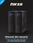
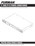
16E09-101
Universal Electronic Temperature Control
INSTALLATION AND
OPERATION INSTRUCTIONS
Save these instructions for future use!
DESCRIPTION
The 16E09-101 is a single stage electronic temperature control, with a Nema 1 rated enclosure, and can be used for most
applications within the temperature control range of -40° to
220°F, (-40° to 104°C). The control has an SPDT (Single Pole
Double Throw) output load relay.
The control has user options to control differential, anti-short
cycle delay, set back, offset, alarms and more. It includes an
NTC (Negative Temperature Coefficient) thermistor temperature sensor, and can be used with certain other NTC or PTC
(Positive Temperature Coefficient) thermistors that meet the
specified resistance vs. temperature specifications. See the
tables on page 7.
The control can fit many applications, which range from
refrigeration to heating due to the wide temperature range of
the control stated above. Typical applications include walkin freezers, beverage coolers, supermarket display cases
for flowers, produce, meats, convenience store refrigerated
cases, food warmers, boiler control, and certain industrial
applications.
PRECAUTIONS
!
WARNING
•
Failure to read and follow all instructions carefully before
installing or operating this control could cause personal
injury and/or property damage.
•
To prevent scald injury, do not use this control to
heat water for bathing, washing, hot tub or similar
applications.
•
To prevent electrical shock, personal injury and/or
equipment damage, disconnect electric power to system
at main fuse or circuit breaker box prior to installation
or service.
•
Where failure of this control may result in personal
injury and/or property damage, additional alarms or limit
controls must be installed.
•
This control is a temperature control and is not to be
used as a temperature limit control.
16E09-101 Optional Accessories / Service Items:
CONTENTS
Basic Description......................................................... 1
Precautions.................................................................. 1
Installation.................................................................... 2
Wiring........................................................................... 3
User Menu................................................................... 4
Operation..................................................................... 5
Specifications............................................................... 7
Troubleshooting............................................................ 8
Immerson Well . ................................................... F89-0286
Replacement 7.5' NTC Remote Sensor............... F136-0114
Well Heat Transfer Compound.............................. F145-0163
www.white-rodgers.com
www.emerson.com
PART NO. 37-6857G
Replaces 37-6857F
1016
INSTALLATION
To prevent electrical shock and/or equipment damage, disconnect electric power to system at main
fuse or circuit breaker box prior to installation or
service.
Where failure of this control may result in personal
injury and/or property damage, additional alarms or
limit controls must be installed.
This control is a temperature control and is not to
be used as a temperature limit control.
The control has a user selection for changing the setpoint to
be either the Cut In or the Cut Out setting. The user must be
careful to understand how this effects the “range” in which
the control will operate when the differential value is entered.
If entered values are incorrect, the control could operate
outside the user’s intended settings due to set-up error. See
section titled "Operation".
Circuit Board
Inside Cover
Fig. 1 Control Front View and Description
TEMPERATURE UNITS INDICATOR (°F or °C)
SETPOINT TEMPERATURE
ACTUAL TEMPERTURE
AT TEMPERATURE SENSOR
HEATING MODE INDICATOR (
)
SW1
COOL
BINARY INPUT INDICATOR
LIT WHEN UNIT IS IN
“SETBACK” MODE
REFER TO PAGE 6
SW1
COOL
COOLING MODE INDICATOR (
STATUS INDICATOR LED
LIT WHEN CONTROLLED LOAD
IS ENERGIZED (ON).
(SEE NOTE)
MENU BUTTON
PRESS TO ENTER MENU MODE
REFER TO PAGES 4 & 5
HEAT
)
Switch SW1 must be set for
system mode as shown:
TEMPERATURE “UP” BUTTON
SW1
TEMPERATURE “DOWN” BUTTON
Refrigeration
Cool
Heating
Heat
NOTE:
Green Status Indicator LED and display backlight operation
It may be observed from time to time that the green status indicator LED and
display back-light will briefly turn off during a call for heating or cooling. During this
time, the control is performing a self-check lasting up to 15 seconds. This is normal
operation of the control and the load power will be maintained
Fig. 2 Control Dimensions and Mounting Information
FRONT VIEW
LEFT SIDE VIEW
REAR VIEW
RIGHT SIDE VIEW
1.58”
2.91”
6.73”
.85”
.85”
2.8”
2.54”
.76”
2
4.19”
5.59”
5.59”
BOTTOM VIEW
1.54”
HEAT
WIRING
Alarm Output
For optional connection
to customer alarm equipment
Line Voltage (Power Stealing)
PS
Line Voltage (Non Power Stealing)
Non PS
24 VAC (Non Power Stealing)
Non PS
GND
BIN
Power Stealing Compatibility Chart
Power
Stealing
Non-Power
Stealing
Line Voltage, replacing existing
control that has a common wire
Yes
Yes
Line Voltage, with load greater
than 2.5 amps, without Defrost
timer or other power interruption
circuit, with or without alarm
Yes
Yes
Line Voltage, with load greater
than 2.5 amps, with Defrost
timer of other power interruption
circuit, no alarm
See
Note 1
Line Voltage with load greater
than 2.5 amps, with Defrost
timer or other power Interruption
circuit, with alarm
No
Line Voltage with load less than 2.5
amps
No
Yes
24 VAC Application
No
Yes
Binary Input
(Gold Plated
Contacts)
PS
SW2
NON
PS
LOAD
LINE
NEUT
NC
Power Stealing
Power Stealing is an electronic design within the control that
can eliminate the need to connect a neutral line to power the
control. The control receives power from the unit it is controlling. Power Stealing saves time and money by often eliminating the labor to run a neutral wire to the control for power. See
compatibility chart below for certain limitations.
Application
PTC
NTC
NTC*
Temperature
Sensor
Hot
208/240
VAC
L1
Neutral
L2
Fig. 4 Line Voltage Application
(Non-Power Stealing)
Alarm Output
For optional connection
to customer alarm equipment
PTC*
Temperature
Sensor
NTC*
Temperature
Sensor
Yes
PTC
Hot
208/240
VAC
L1
Neutral
L2
Binary Input
(Gold Plated
Contacts)
PS
SW2
NON
PS
Voltage Input
120 VAC
GND
BIN
LOAD
LINE
NEUT
NC
NOTE 1: During defrost or time when load circuit is broke,
display will be blank because power has been
interrupted to the control. All menu settings and
setpoint will be restored when power is returned.
24 VAC
TH TR
24 VAC (Block not used)
TH - Thermostat Hot
TR - Thermostat Return
Load
Fig. 5 24 VAC Applications
(Non-Power Stealing)
Alarm Output
For optional connection
to customer alarm equipment
PTC*
Temperature
Sensor
PTC
NTC
NTC*
Temperature
Sensor
Binary Input
(Gold Plated
Contacts)
GND
BIN
Note: Do not use Output
Relay to control Line Voltage
when using 24 VAC Power
PS
SW2
NON
PS
LOAD
LINE
NEUT
NC
* NTC – Negative Temperature Coefficient
PTC – Positive Temperature Coefficient
24 VAC (Block not used)
TH - Thermostat Hot
TR - Thermostat Return
Load
NTC
Yes
24 VAC
TH TR
Voltage Input
120 VAC
(See "Special Note"
in "Operation Section"
for Alarm)
ALARM
PTC*
Temperature
Sensor
SW2
ALARM
Switch Settings
Switch SW2 must be set for applications as shown:
Fig. 3 Line Voltage Application
(Power Stealing)
ALARM
Wiring Instruction Notes
24 VAC
TH TR
NC contact
operates opposite
of load contact
NOTE: Only one sensor (PTC or NTC) may be connected. Sensor must
meet specific temperature vs. resistance specifications.
Load
24 VAC
TH - Thermostat Hot
TR - Thermostat Return
24 VAC
Class 2
Transformer
3
USER MENU
USER MENU OPERATION SETTINGS:
The control has user Menu settings that will determine how
the control operates. The unit is shipped with factory default settings. The user must change any of the settings as
required for the application. To reset all settings to factory
,
defaults, press and hold all 3 buttons simultaneously (
, and
buttons) for approximately 5 seconds.
To view Menu items, press and hold
for 5 seconds.
The unit will display the first Menu item on the left side of the
display. The right side of the display indicates the Menu item
settings. To change the setting, momentarily press the
or
key.
A momentary press of the
key advances the display to
the next Menu item, and continues, till the last menu item is
displayed. Pressing the key one more time with the last menu
item, (aL) displayed returns the control to the operating mode.
Menu
Item
Description
CF
Temperature Scale
dFF
Differential
SP
Set Point Mode
Cool
Heat
SOF
dL
ASd
Sensor Operation Failure
Cool
Heat
Display Light
Anti Short-Cycle Delay
Factory
Default
F
Each press of
results in forward movement to the next
Menu item. If you need to change an item “passed”, you
, return to the operating mode,
must repeatedly press
then press and hold
for 5 seconds to re-enter the Menu
mode. Then repeatedly, momentarily press
until the
desired Menu item is again displayed.
To store any changes made to any Menu items, the Menu
must be exited by pressing
when the last item is
displayed. If no buttons are pressed for ten minutes while in
the menu, the control will return to operating mode and any
changes that were made will be lost.
The following table shows the menu items, default settings
and optional settings.
NOTE: The Heat/ Cool switch (SW1) MUST be in the proper
position BEFORE setting options.
Options
Press
or
to select
C or F
Selects temperature display in Fahrenheit or Celsius
Selects the range between Cut In and Cut Out.
5
1 to 30
Cl
CO
CO or CI
CI or CO
Selects how the set point temperature will operate the
load terminal. CI indicates the setpoint temperature
will be the Cut In temperature. CO indicates the
temperature will be the Cut Out temperature. See
Operation section.
1
0
0 or 1
None
Cooling - Selects the operation of the Control Load
relay in the event of a sensor failure in Cool mode. 1
(default) will cause the load contacts of the relay to
close and remain closed if the sensor either opens or
shorts. 0 causes the load contacts of the relay to open
and remain open.
Heating has no optional selection. Sensor failure
in Heating will result in the relay contacts opening.
Off
On or Off
Selects the LCD display light Off or On. With this
selected Off, the display light will illuminate any time a
keypad button is pressed to provide better viewing in
low lighting conditions, and go off after 10 seconds. If
On is selected, the display light will be On continuously.
Cool
1
0 to 12
Selects the minimum time (in minutes) that the load
contacts will remain open after a cycle before closing
again. This will prevent the compressor or other load
from being damaged by cycling too soon. A blinking
Snowflake or Flame icon indicates that the control has
a demand to energize the load, but is waiting for the
delay time to elapse. A setting of 0 indicates no time
and the feature is disabled. SW1 must be set to the
proper position before checking this setting.
Off
On or Off
When selected Off, the keypad can be used as normal.
When selected On, prevents unauthorized access to
the control settings by locking out all keys. To unlock
the control when it is locked, press and hold the Menu
key for 5 seconds.
0
-4, -3, -2, -1, 0,
1, 2, 3, 4
This control is calibrated at the factory, but the “sensed"
temperature may read different because of mounting/installation, or other factors. This item allows the
displayed temperature to be shifted the number of
degrees set to compensate for this difference
Heat
0
LP
OFS
4
Lock Front Panel Keypad
Ambient Temperature
Offset
Comments
USER MENU
Menu
Item
Description
bIn
Binary Input
Sb
AL
Factory
Default
Options
Press
or
to select
Comments
Off
On or Off
The default setting of Off will have no affect on the
operation of the thermostat. When set to On, it allows
an external binary input (switch or relay) to start a temperature set back. See Set Back (Sb).
Set Back
0
0 to 50
Selects the number of degrees the thermostat will
change the setpoint temperature when the external
binary input signal is received. 0 will cause no temperature change to occur. See Binary Input (bin).
Alarm
0
0 to 99
Selects the time delay (in minutes) before a Temperature Out of Range alarm output is sent.
A setting of 0 disables the alarm relay.
OPERATION
To prevent scald injury, do not use this control to
heat water for bathing, washing, hot tub or similar
applications.
The factory default setpoint for this control is 45°F (7°C) for
Cool and 120°F (49°C) for Heat. Setpoint temperature can
be adjusted using the
or
keys. A power loss does not
lose the settings. All menu item selections and setpoint setting are stored in a permanent memory.
The user determines the temperature operating range. To
determine the temperature range, the user must select the
Set Point (SP) as the Cut Out or Cut In temperature, Differential (dFF) and enter a set point temperature. Cut out
is when the load is turned off and cut in is when the load is
turned on.
NOTE: The Heat/ Cool switch (SW1) MUST be in the proper
position BEFORE setting options.
COOL/REFRIGERATION
To use as a Cooling control, SW1 must be set to Cool. The
snowflake ( ) icon will display.
If control is in Cool mode, and Set Point is selected as the
Cut In:
Temperature
Operating
= Setpoint
–
Differential
(minus)
Range
Temperature
40° Setpoint (Cut In)
Example:
SW1 = Cool
Set Point (SP) = Cut Out
Differential = 5
Setpoint temperature = 40°
45°
40° Setpoint (Cut Out)
HEAT
To use as a Heating control, SW1 must be set to Heat. The
flame ( ) icon will display.
If control is in Heat mode, and Set Point is selected as the
Cut Out:
Temperature
Operating
= Setpoint
–
Differential
Range Temperature (minus)
Example: SW1 = Heat
Set Point (SP) = Cut Out
Differential = 5
Setpoint temperature = 100°
100° Setpoint (Cut Out)
95°
If control is in Heat mode, and Set Point is selected as the
Cut In:
Temperature
Operating
= Setpoint
+
Differential
Range Temperature (plus)
Example:
35°
SW1 = Heat
Set Point (SP) = Cut In
Differential = 5
Setpoint temperature = 100°
emperature
an e
SW1 = Cool
Set Point (SP) = Cut In
Differential = 5
Setpoint temperature = 40°
Temperature
Range
Example:
If control is in Cool mode, and Set Point is selected as the
Cut Out:
Temperature
Operating
= Setpoint
+
Differential
Range Temperature (plus)
Temperature
Range
This control is a temperature control and is not to
be used as a temperature limit control.
Temperature
Range
105°
100° Setpoint (Cut In)
5
OPERATION
Lock Panel (LP)
The keypad can be locked to prevent unwanted tampering
with the control settings. In the User Menu, change the menu
item LP selection to On. When the menu is exited and setor , and
keys will be disabled
tings are stored, the
from normal use.
for 5 seconds.
To unlock the keypad, press and hold
The display will change to show LP On. Momentarily press
or
to change to Off and then momentarily press
.
The control will return to normal operation and the keypad
will be unlocked.
Binary Input (bIn) and Set Back (Sb)
Binary Input is an option to allow the setpoint temperature
to set back to conserve energy or for other reasons as
determined by the user. Set Back determines the number of
degrees the setpoint temperature will be changed.
An external switch or N.O. relay can be connected to the BIN
and GND terminals of the control. With bIn set to On, when
the switch is closed, the control will change the setpoint temperature by the number of degrees set in Sb. In Heat mode,
setpoint temperature will change lower or cooler. In Cool
mode, setpoint temperature will change higher or warmer.
During the time that the switch is closed, bIn will appear in
the lower left corner of the display. If an alarm is connected
be sure that the alarm delay time is set long enough to allow
for the temperature change to avoid a “false” alarm.
Alarm (AL)
IAL
Using the Alarm Output and power
EC E
P
S OT
stealing in combination – When using
N
power stealing mode and the alarm output, it is
important for the installer to review the wiring circuit
of the installation to insure no device is present that could
interrupt electrical power to the temperature control. Such
a device could be a defrost timer, as one example, that may
be used in some refrigeration applications.
If a device is in the system wiring that can periodically
disrupt power to the load and the temperature control,
the power stealing mode of the control cannot be used. A
neutral wire must be connected to the control and select
the non power stealing mode for the control. This keeps
power to the control during power interruptions to the load
and avoids a “false” alarm output.
This control has an alarm relay that will provide an output to
alert of a malfunction. The alarm relay output must be connected to an external light, audible alarm or other device as
needed by the user. If AL is set to 0, the alarm relay will not
provide any alarm output. If AL is set to a value greater than
0, the alarm relay output provides indication of three error
conditions: Temperature Out of Range, Power Loss and Sensor Operation Failure. Although AL must be set to a value
greater than 0 for any alarm output to be provided, the value
selected is the time delay, in minutes, before a Temperature
Out of Range alarm is set. The alarm time delay does not
apply to Power Loss or Sensor Operation Failure.
6
Temperature out of range – If the temperature is more than
5° from the setpoint, continuously for the length of time set in
AL, the alarm relay output will close. The delay should be set
to allow for conditions that will cause the temperature to vary,
such as defrost cycle, opening door for stock removal or
replacement or Set Back changes. When setting the AL time,
consideration should be given to these events to prevent a
false alarm.
If the control set back feature is used to change the setpoint,
the delay period set in AL should consider the time it takes
for the system to reach the set back temperature to avoid a
false alarm.
Power Loss – If the temperature control experiences an input
power failure, the control will close the alarm relay before
total power of the control is lost. The delay time is not used in
this event, and the alarm relay will close within seconds of a
power failure. In addition, the load relay contact change state
per the Sensor Operation Failure (SOF) setting.
When power returns, the alarm contacts will open. The load
relay will remain in the SOF position the length of time set in
Anti Short-Cycle Delay (ASd) after power resumption. The
display will blink the flame or snowflake icon for this time to
indicate the load is “locked” out. This is to help protect the
user’s equipment from damage by short cycle switching.
Sensor Operation Failure (SOF) – If in operation, the sensor wiring should become open or shorted, the temperature
control will begin blinking SOF with SH for shorted or SO for
sensor open. However, the control will wait approximately
1 minute before closing the alarm output relay - indicating
sensor operation failure. If during the 1 minute, the sensor
“resumes” normal operation, the time is reset and the control
returns to normal display. The load relay will operate as selected in sensor operation failure (SOF).
Multiple Sensors
The 16E09 is normally operated with one sensor. If an average temperature of an area is required, 4 sensors may be
used and wired in the method shown below. If 4 sensors are
used, they must all be of the same model.
Sensor 1
Sensor 3
Sensor 2
Sensor 4
NOTE: When using multiple sensors, 4 sensors must be
used. The control will not operate with 2 or 3 sensors.
SPECIFICATIONS
Load Output Relay: Ratings (Maximum):
120VAC 208VAC 240VAC
Full Load Amps NC & Load
16 A
9.2 A 8 A
Locked Rotor Amps NC & Load
96 A
55.2 A 48 A
Non-Inductive Amps NC & Load
16 A
16 A
16 A
Horsepower NC & Load
1 hp
1 hp
1 hp
24 VAC NC & Load
100 VA, 30 VAC Max (Class 2)
Pilot Duty NC & Load
125 VA, 24 to 240 VAC
• Minimum Load Rating: 1 Amp @ 24 VAC
• Note: the above minimum current/voltage is specified
to assure proper operation.
Operating Ambient Ratings (Control Enclosure):
Operating Temperature: -29°F to 140°F (-34° to 60°C)
Storage Shipping Ambient Ratings:
Storage Temperature:
-40°F to 185°F (-40° to 85°C)
Operating Humidity:
0 to 95% Relative Humidity,
Non-Condensing
Maximum Dew Point: 85°F (29°C)
Temperature Set-Point Range:
Set-Point Range: -40° to 220°F (-40° to 104°C)
Differential Range:
1 to 30 (Degrees F or Degrees C)
Case:
NEMA 1 Enclosure, Flammability Rating: UL94VO
NOTE: For use on single phase circuits only.
Alarm Relay Ratings (Maximum):
N.O. contact: 1 Amp, 5 to 24 V, AC or DC
Temperature Probes:
NTC
The control is shipped with an NTC (Negative Temperature
Coefficient) sensor, with a cable length of 7½ feet. Cable
length can be extended up to 400 feet by appropriately splicing and adding additional cable (22 AWG or larger diameter)
as needed – polarity is not important. When extending cable
length, verify temperature accuracy and use the menu Ambient Temperature Offset (OFS) settings to compensate accordingly if required.
NTC TEMPERATURE VERSUS RESISTANCE TABLES
Temperature
(°F)
(°C)
-40
-31
-22
-13
-4
5
14
23
32
41
-40
-35
-30
-25
-20
-15
-10
-5
0
5
Resistance
(KΩ)
328.29
236.83
172.90
127.65
95.23
71.74
54.56
41.85
32.37
25.23
Temperature
(°F)
(°C)
50
59
68
77
86
95
104
113
122
131
10
15
20
25
30
35
40
45
50
55
PTC
The control may be connected to an existing PTC (Positive
Temperature Coefficient) sensor. Make sure the PTC sensor
meets the specifications tables below. Failure to do so will
result in temperature inaccuracies. The PTC input may not be
Resistance
(KΩ)
19.82
15.67
12.48
10.00
8.07
6.55
5.34
4.38
3.61
2.99
Temperature
(°F)
(°C)
140
149
158
167
176
185
194
203
212
221
60
65
70
75
80
85
90
95
100
105
Resistance
(KΩ)
2.49
2.09
1.76
1.48
1.26
1.07
0.92
0.79
0.68
0.59
extended more than 50 feet, and the wire gauge should be
18 AWG wire or larger diameter. Be sure the probe attached
matches the resistance vs. temperature tables or temperature
inaccuracies may occur.
PTC TEMPERATURE VERSUS RESISTANCE TABLES
Temperature
(°F)
(°C)
-40
-31
-22
-13
-4
5
14
23
32
41
-40
-35
-30
-25
-20
-15
-10
-5
0
5
Resistance
(KΩ)
613
640
668
697
727
758
789
822
855
889
Temperature
(°F)
(°C)
50
59
68
77
86
95
104
113
122
131
10
15
20
25
30
35
40
45
50
55
Resistance
(KΩ)
924
960
997
1035
1074
1113
1153
1194
1236
1279
Temperature
(°F)
(°C)
140
149
158
167
176
185
194
203
212
221
60
65
70
75
80
85
90
95
100
105
Resistance
(KΩ)
1323
1368
1413
1459
1506
1554
1602
1652
1702
1753
7
TROUBLESHOOTING
LCD display, display back-light and green status indicator LED turn off in Power Stealing mode:
This “off” condition is normal for the control in power stealing
mode when wired with a defrost timer or other device that
interrupts electrical power to the control.
No control settings will be lost during this time, however, the
installer must ensure that applications requiring power stealing are suitable for the control to be off during these periods.
Please note: if the built-in alarm feature of the control is to
be used on systems that may interrupt power to the control,
the control must be wired with a neutral wire and set in nonpower stealing mode. This will keep the control continuously
powered unless there is an actual power interruption or loss.
In this case, the control will be able to signal an alarm for
system power loss.
Display indicates “CaL” on power up.
Control was not calibrated. Return control for replacement.
Unit does not turn on, (LCD does not display anything):
- Check that wiring is correct.
- Make sure power is turned on.
- Check that wiring is under terminal blocks correctly.
- Make sure both switches inside control are set to proper
position.
- If in Power Steal mode,
- Make sure the load draws a minimum of 2.5 amp AC. If
not, wire per the Non-Power Stealing diagram.
- Make sure nothing "breaks/opens the load line, such as
a defrost timer or any other device, with the alarm
feature enabled. This would cause a false alarm. If the
alarm function is enabled, wire per the Non-Power
Stealing diagram.
Temperature differential is wider than set:
- Temperature change of customer's unit is fast, and the Anti Short Cycle delay setting may be overriding the “call” to activate the heat or cool. Solution – lower Anti Short Cycle delay.
Installation and Power Up:
False alarm sounds, temperature has not yet reached setpoint setting. CUSTOMER must disable alarm (AL = 0), until
setpoint temperature is reached, then set alarm delay time.
Customer Changes Setpoint Temperature:
False alarm sounds. CUSTOMER must disable alarm
(AL = 0), while unit is adjusting to new temperature. CUSTOMER must then set the alarm delay time when temperature is reached.
Bin/Set Back
False alarm sounds. CUSTOMER must set the delay time
with sufficient delay time to assure the Set Back temperature
is reached before the alarm delay time has expired.
Note: If the Set Back temperature cannot be reached within
99 minutes (the maximum Alarm delay time), change the
Set Back value to a lower number of degrees. If a lower set
back can not be used, you may not be able to use the alarm
feature.
Alarm Sounds, Reason Unknown:
CUSTOMER should make sure the Alarm (AL) delay time is
great enough to cover other conditions when the unit temperature may not be able to stay within 5 degrees.
- Loading or unloading of stock and the doors are open.
(Add sufficient delay time to the alarm delay).
- Power is lost to the control if the line is broken/open by a
defrost timer or other device. (Wire control per the Non
Power Stealing line voltage schematic and connect/add
a neutral line connection).
tech support help line: 1-888-725-9797
White-Rodgers is a division
of Emerson Electric Co.
The Emerson logo is a
trademark and service mark
of Emerson Electric Co.
www.white-rodgers.com
www. emerson.com
SOLUCIÓN DE PROBLEMAS
Pantalla LCD, luz de fondo de pantalla e indicador verde de
estado LED se apaga en el modo Power Stealing:
La condición de apagado es normal para el control en el
modo Power Stealing cuando se conecta con un reloj de
descongelamiento u otro dispositivo que interrumpa el suministro eléctrico al control.
No se perderá ningún ajuste del control durante este tiempo.
No obstante, el instalador deberá asegurarse de que las aplicaciones que requieran Power Stealing sean adecuadas para
que el control se apague durante estos períodos.
Atención: si la característica de alarma incorporada del
control debe usarse en sistemas que pueden interrumpir la
alimentación al control, éste debe conectarse con un cable
neutro y configurarse en el modo Non-Power Stealing. Esto
mantendrá el control continuamente encendido a menos que
se produzca una interrupción o pérdida de alimentación. En
este caso, el control podrá activar una alarma de pérdida de
alimentación del sistema.
La pantalla indica “CaL” al encenderse.
El control no estaba calibrado. Envíe de vuelta el control a la
fábrica para su reemplazo.
La unidad no se enciende (la pantalla LCD está en blanco):
- Verifique que las conexiones se hayan realizado
correctamente.
- Asegúrese de que la alimentación esté encendida.
- Verifique que las conexiones pasen correctamente por
debajo de los bloques de terminales.
- Asegúrese de que ambos interruptores que se encuentran dentro del control estén ajustados en la posición adecuada.
- Si lo utiliza en el modo Power Steal:
- Asegúrese de que la carga atraiga un mínimo de 2.5 amp CA. De lo contrario, conecte según el diagrama Non-Power Stealing.
- Asegúrese de que nada interrumpa o abra la línea de carga, como un temporizador de descongelación o cualquier otro dispositivo, con la función de alarma
activada. Esto produciría una falsa alarma. Si la función de alarma está activada, conecte según el diagrama de Non-Power Stealing.
Instalación y encendido:
Suena una falsa alarma, la temperatura aún no ha llegado a
la temperatura de referencia. El CLIENTE debe desactivar la
alarma (AL = 0), hasta alcanzar la temperatura de referencia
y luego ajustar el tiempo de demora de la alarma.
El cliente cambia la temperatura de referencia:
Suena una falsa alarma. El CLIENTE debe desactivar la
alarma (AL = 0), mientras la unidad se adapta a la nueva
temperatura. Luego el CLIENTE debe ajustar el tiempo de
demora de la alarma cuando se alcanza la temperatura.
Bin/Reducción de la temperatura
Suena una falsa alarma. El CLIENTE debe ajustar el tiempo
de demora a un valor suficiente que permita alcanzar la temperatura reducida antes de que haya transcurrido la demora
de la alarma. Nota: si no es posible alcanzar la temperatura
reducida dentro de los 99 minutos (el tiempo de demora de
alarma máximo), cambie el valor de la temperatura reducida a una cantidad de grados menor. Si no se puede usar
una temperatura inferior, es posible que no pueda utilizar la
función de alarma.
Suena la alarma, causa desconocida:
El CLIENTE debe asegurarse de que el tiempo de demora de
la Alarma (AL) sea lo suficientemente amplio para contemplar
otras situaciones en las que es posible que la temperatura de
la unidad no pueda permanecer dentro de los 5 grados.
- Apertura de las puertas para colocar agregar o retirar
productos. (Agregue suficiente tiempo de demora a la
demora de la alarma.)
- Se interrumpe la alimentación al control si la línea es
interrumpida o abierta por un temporizador de desconge-
lación u otro dispositivo. (Conecte el control según el esquema de voltaje de línea Non-Power Stealing y conecte o agregue una línea neutra.)
El diferencial de temperatura es más amplio que el ajustado:
-El cambio de temperatura de la unidad del cliente es rápido
y el ajuste de demora anti-ciclo corto podría estar anulando
la “llamada” para activar la calefacción o la enfriamiento.
Solución: reduzca la demora anti-ciclo corto.
LÍNEA DE SOPORTE TÉCNICO: 1-888-725-9797
White-Rodgers es una división
de Emerson Electric Co.
El logotipo de Emerson
es una marca comercial y
una marca de servicio de
Emerson Electric Co.
www.white-rodgers.com
www.emerson.com
ESPECIFICACIONES
Relé de salida de carga: Valores nominales
eléctricos (máximos):
120VCA 208VCA 240VCA
Carga total A NC y carga
16 A
9.2 A
8A
Rotor bloqueado A NC y carga
96 A
55.2 A
48 A
No inductivo A NC y carga
16 A
16 A
16 A
Caballos de fuerza NC y carga
1 hp
1 hp
1 hp
24 VCA NC y carga 100 VA, 30 VCA máx. (clase 2)
Piloto NC y carga 125 VA, 24 a 240 VCA
• Carga mínima nominal: 1 A a 24 VCA
• Nota: la corriente/voltaje mínimos anteriores están
especificados para asegurar un funcionamiento
adecuado.
NOTA: para uso en circuitos de una sola fase únicamente.
Valores nominales eléctricos del Relé de alarma
(máximos):
Contacto N/O: 1 A, 5 a 24 V, CA o CC
Valores ambientales operativos nominales (Caja de
control):
Temperatura operativa: -29°F a 140°F (-34° a 60°C)
Valores ambientales de almacenamiento y transporte
nominales:
Temperatura de almacenamiento: -40°F a 185°F (-40° a 85°C)
Humedad operativa:
0 a 95% humedad relativa,
sin condensación
Punto de rocío máximo: 85°F (29°C)
Rango de temperaturas de referencia:
Rango de referencia:
-40° a 220°F (-40° a 104°C)
Rango diferencial:
1 a 30 (°F o °C)
Caja:
Caja NEMA 1, calificación de inflamabilidad: UL94VO
Sondas de temperatura:
NTC
El control incluye un sensor NTC (coeficiente de temperatura
negativo), con un cable de 7½ pies de longitud. La longitud
del cable puede extenderse hasta 400 pies empalmando y
agregando cable adicional (22 AWG o un diámetro mayor)
según sea necesario. La polaridad no es importante. Si extiende la longitud del cable, verifique que la temperatura sea
precisa y utilice los ajustes de compensación de temperatura
ambiente (OFS) del menú para compensarla en caso de que
sea necesario.
TABLAS DE TEMPERATURA VS. RESISTENCIA NTC
Temperatura
(°F) (°C)
-40 -40
-31 -35
-22 -30
-13 -25
-4
-20
5
-15
14
-10
23
-5
32
0
41
5
Resistencia
(KΩ)
328.29
236.83
172.90
127.65
95.23
71.74
54.56
41.85
32.37
25.23
Temperatura
(°F) (°C)
50
59
68
77
86
95
104
113
122
131
10
15
20
25
30
35
40
45
50
55
PTC
El control podrá conectarse a un sensor PTC (coeficiente de
temperatura positivo) existente. Asegúrese de que el sensor
PTC cumpla con las especificaciones de las tablas incluidas
a continuación. De lo contrario, podrían producirse imprecisiones de temperatura. La entrada PTC no podrá extenderse
Resistencia
(KΩ)
19.82
15.67
12.48
10.00
8.07
6.55
5.34
4.38
3.61
2.99
Temperatura
(°F) (°C)
140
149
158
167
176
185
194
203
212
221
60
65
70
75
80
85
90
95
100
105
Resistencia
(KΩ)
2.49
2.09
1.76
1.48
1.26
1.07
0.92
0.79
0.68
0.59
más de 50 pies y el cable deberá tener un calibre de 18
AWG o un diámetro más grande. Asegúrese de que la sonda
conectada sea compatible con las especificaciones de las
tablas de resistencia vs. temperatura, ya que de lo contrario
podrían producirse imprecisiones de temperatura.
TABLAS DE TEMPERATURA VS. RESISTENCIA PTC
Temperatura
(°F) (°C)
-40
-40
-31
-35
-22
-30
-13
-25
-4
-20
5
-15
14
-10
23
-5
32
0
41
5
Resistencia
(Ω)
613
640
668
697
727
758
789
822
855
889
Temperatura
(°F) (°C)
50
59
68
77
86
95
104
113
122
131
10
15
20
25
30
35
40
45
50
55
Resistencia
(Ω)
924
960
997
1035
1074
1113
1153
1194
1236
1279
Temperatura
(°F) (°C)
140
149
158
167
176
185
194
203
212
221
60
65
70
75
80
85
90
95
100
105
Resistencia
(Ω)
1323
1368
1413
1459
1506
1554
1602
1652
1702
1753
7
FUNCIONAMIENTO
Bloquear panel (LP)
El teclado puede bloquearse para impedir la modificación indeseada
de los ajustes de control. En el menú del usuario, cambie la opción
de menú LP a On. Al salir del menú, cuando se guarden los ajustes,
las teclas
o ,y
quedarán desactivadas del uso normal.
Para desbloquear el teclado, presione
y manténgalo
presionado durante 5 segundos. La pantalla cambiará y mostrará LP
On. Presione
o
por un momento para cambiar el ajuste a Off
y luego presione
durante algunos instantes. El control volverá
a su funcionamiento normal y el teclado quedará desbloqueado.
Entrada binaria (bIn) y Reducción de la
temperatura (Sb)
Entrada binaria es una opción que permite reducir la temperatura de
referencia para ahorrar energía o por otras razones determinadas
por el usuario. La opción Reducción de la temperatura determina
la cantidad de grados en que se modificará la temperatura de
referencia.
Puede conectarse un interruptor externo o relé N/O a las terminales
BIN y GND del control. Cuando la opción bIn se ajusta en On, al
cerrar el interruptor, el control cambiará la temperatura de referencia
la cantidad de grados indicada en Sb. En el modo Calor, la temperatura de referencia se reducirá o será más fría. En el modo Frío, la
temperatura de referencia aumentará o será más cálida.
Mientras el interruptor está cerrado, aparecerá la leyenda “bIn” en el
ángulo inferior izquierdo de la pantalla. Si la alarma está conectada,
asegúrese de que la demora sea lo suficientemente larga para permitir el cambio de temperatura y evitar una “falsa” alarma.
Alarma (AL)
L
Uso combinado de salida de alarma y
TA
NO ECIA Power Stealing – Cuando se utilice el modo
P
ES
Power Stealing y la salida de alarma, es importante
que el instalador revise el circuito de cableado de la
instalación para asegurarse de que no haya presente ningún
dispositivo que pudiera interrumpir el suministro eléctrico
al control de temperatura. Dicho dispositivo podría ser un
reloj de descongelamiento, por ejemplo, como el que se
utiliza en algunas aplicaciones de enfriamiento.
Si hay algo en el cableado del sistema que puede
interrumpir periódicamente la alimentación al control de
temperatura, no podrá usarse el modo Power Stealing del
control. Es necesario conectar un cable neutro al control y
seleccionar el modo Non-Power Stealing. Esto mantendrá
la alimentación al control durante las interrupciones de
suministro y evitará una “falsa” alarma.
Este control cuenta con un relé de alarma que alerta acerca de
una falla. La salida del relé de alarma debe conectarse a una luz
externa, alarma audible u otro dispositivo, según las necesidades
del usuario. Si AL se ajusta en 0, el relé de alarma no proporcionará
ninguna salida de alarma. Si AL se ajusta a un valor mayor que
0, la salida del relé de alarma indicará tres condiciones de error:
Temperatura fuera de rango, Interrupción de alimentación y Falla de
funcionamiento del sensor. Aunque la opción AL debe ajustarse a un
valor mayor que 0 para proporcionar una alarma, el valor seleccionado es la demora, en minutos, antes de que se active una alarma
de Temperatura fuera de rango. La demora del tiempo de alarma no
se produce en el caso de Interrupción de la alimentación o Falla de
funcionamiento del sensor.
Temperatura fuera de rango – Si la temperatura difiere de la temperatura de referencia en más de 5° en forma continua durante el
tiempo definido en AL, la salida del relé de alarma se cerrará. La demora debe ajustarse de modo tal de que contemple situaciones que
hacen que la temperatura varíe, como el ciclo de descongelación, la
apertura de la puerta para retirar o reponer artículos o cambios en la
reducción de la temperatura. Cuando se ajusta el tiempo AL, deben
tenerse en cuenta estas situaciones para evitar falsas alarmas.
Si se utiliza la función de reducción de la temperatura del control
para cambiar la temperatura de referencia, el período de demora
ajustado en AL debe tener en cuenta el tiempo que tarda el sistema
en alcanzar la temperatura reducida para evitar falsas alarmas.
Interrupción de la alimentación – Si el control de temperatura
experimenta una falla en la alimentación de entrada, el control
cerrará el relé de alarma antes de que se interrumpa totalmente la
alimentación al control. En este caso no se utiliza el tiempo de
demora y el relé de alarma se cerrará a los pocos segundos de
producida una falla en el suministro. Además, el contacto del relé
de carga cambiará de estado según el ajuste de Falla en el
funcionamiento del sensor (SOF).
Cuando se restablece la alimentación, los contactos de la alarma
se abrirán. El relé de carga permanecerá en la posición SOF por
la cantidad de tiempo especificada en Demora anti-ciclo corto
(ASd) después de que se restablezca la alimentación. La pantalla
mostrará un icono intermitente con forma de llama o de copo de
nieve durante ese tiempo para indicar que la carga está “bloqueada”
y proteger el equipo del usuario contra posibles daños por la conmutación en ciclos cortos.
Falla de funcionamiento del sensor (SOF) – Si durante su
funcionamiento, las conexiones del sensor se abren o entran
en cortocircuito, el control de temperatura comenzará a mostrar
en forma intermitente la leyenda SOF acompañada de SH, en el
caso de un cortocircuito, o SO, en el caso de un sensor abierto.
No obstante, el control esperará aproximadamente 1 minuto
antes de cerrar el relé de salida de alarma, que indica una falla
de funcionamiento del sensor. Si durante ese minuto el sensor
“reanuda” su funcionamiento normal, el tiempo se restablece y
el control vuelve a mostrar una pantalla normal. El relé de carga
funcionará según el ajuste seleccionado en Falla de funcionamiento
del sensor (SOF).
Varios sensores
Normalmente, el 16E09 opera con un sensor. Si se requiere una
temperatura promedio de un área, pueden usarse 4 sensores
conectados de una manera como se muestra a continuación. Si se
usan 4 sensores, todos deben ser del mismo modelo.
Sensor 4
Sensor 2
Sensor 3
Sensor 1
Nota: cuando se usan varios sensores, deben usarse 4. El control
no funcionará con 2 o con 3 sensores.
6
MENÚ DEL USUARIO
Opción
del menú
Descripción
Ajuste
Opciones
de Presione
o
fábrica para seleccionar
0
Alarma
AL
0
Reducción de la temperatura
Sb
Entrada binaria
bIn
Off
On u Off
0 a 50
0 a 99
Observaciones
El ajuste predeterminado de Off no tendrá efecto en el funcionamiento del termostato. Cuando se ajusta en On, permite una
entrada binaria externa (interruptor o relé) para iniciar una reducción de la temperatura. Vea Reducción de la temperatura (Sb).
Selecciona la cantidad de grados que el termostato modificará
la temperatura de referencia cuando se reciba la señal de
entrada binaria externa. Si se selecciona 0, no se producirá
ningún cambio en la temperatura. Vea Entrada binaria (bin).
Selecciona la demora (en minutos) antes de que se envíe
una salida de alarma de Temperatura fuera de rango.
Un ajuste de 0 desactiva el relé de alarma.
FUNCIONAMIENTO DEL USUARIO
!
Este control es un control de temperatura y no debe
! ¡ADVERTENCIA!
usarse como control de límite de temperatura.
Para evitar quemaduras, no utilice este control para
¡ADVERTENCIA!
calentar agua para bañarse, lavarse, llenar tinas de
agua caliente o aplicaciones similares.
La temperatura de referencia predeterminada de fábrica para
este control es de 45°F (7°C) para enfriamiento y de 120°F
(49°C) para calefacción. La temperatura de referencia puede
ajustarse usando las teclas
o
. Si se produce una
interrupción de la alimentación, no se perderán los ajustes.
Todos los ajustes realizados en las opciones del menú y las
temperaturas de referencia quedan guardados en una memoria permanente.
El usuario determina el rango operativo de temperatura.
Para ello, debe definir la temperatura de referencia (SP)
como temperatura de desconexión o de conexión, ajustar el
diferencial (dFF) e ingresar una temperatura de referencia.
Temperatura de desconexión es cuando la carga se desactiva y temperatura de conexión es cuando la carga se activa.
NOTA: El interruptor calor/frío (SW1) DEBE estar en la
posición adecuada ANTES de ajustar las opciones.
COOL/ENFRIAMIENTO
Para usar como control de enfriamiento, el interruptor SW1
debe ajustarse en el modo Cool. Aparecerá un icono con
forma de copo de nieve ( ) .
Si el control está en el modo Cool y la temperatura de
referencia se selecciona como temperatura de conexión:
Rango
operativo de = Temperatura
–
Diferencial
temperatura de referencia (menos)
Ejemplo:
SW1 = Enfriamiento
Temperatura de referencia
(SP) = Temperatura de
conexión
Diferencial = 5
Temperatura de referencia = 40°
Rango de
temperatura
40° Temperatura
de referencia
(Temperatura
de conexión)
35°
Si el control está en el modo Cool y la temperatura de
referencia se selecciona como temperatura de desconexión:
Rango
operativo de = Temperatura
+
Diferencial
temperatura de referencia (más)
Ejemplo:
45°
SW1 = Enfriamiento
Temperatura de referencia (SP) =
Temperatura de desconexión
Diferencial = 5
Temperatura de referencia = 40°
40° Temperatura de
referencia (Temperatura
de desconexión)
CALOR (HEAT)
Para usar como control de calefacción, el interruptor SW1
debe ajustarse en el modo Heat. Aparecerá un icono con
forma de llama ( ).
Si el control está en el modo Heat y la temperatura de
referencia se selecciona como temperatura de desconexión:
Rango
operativo de = Temperatura
–
Diferencial
temperatura de referencia (menos)
Rango de
temperatura
Ejemplo: SW1 = Calefacción
Temperatura de referencia (SP) =
Temperatura de desconexión
Diferencial = 5
Temperatura de referencia = 100°
Rango de
temperatura
100° Temperatura de
referencia (Temperatura
de desconexión)
95°
Si el control está en el modo Heat y la temperatura de
referencia se selecciona como temperatura de conexión:
Rango
operativo de = Temperatura
+
Diferencial
temperatura de referencia (más)
Ejemplo:
SW1 = Calefacción
Temperatura de referencia (SP) =
Temperatura de conexión
Diferencial = 5
Temperatura de referencia = 100°
Rango de
temperatura
105°
100° Temperatura
de referencia
(Temperatura de
conexión)
5
MENÚ DEL USUARIO
AJUSTES DE OPERACIÓN DEL MENÚ DEL USUARIO:
El control tiene ajustes en el menú del usuario que determinan cómo funcionará el control. La unidad viene con ajustes
predeterminados de fábrica. El usuario deberá cambiar
cualquiera de los ajustes según las necesidades para la
aplicación. Para restablecer todos los ajustes a los valores
predeterminados de fábrica, presione y mantenga presionados los 3 botones simultáneamente (botones
, ,y )
durante aproximadamente 5 segundos.
Para ver las opciones del Menú, presione y mantenga
presionada la tecla
durante 5 segundos. La unidad
mostrará la primera opción del menú del lado izquierdo de
la pantalla. El lado derecho de la pantalla indica los ajustes
correspondientes a esa opción del menú. Para modificar un
ajuste, presione por un momento la tecla
o
.
Después de presionar por un momento la tecla
la
pantalla pasará a la siguiente opción del menú, y así sucesivamente hasta llegar a la última opción. Al presionar la tecla
una vez más cuando aparece la última opción del menú (aL)
el control vuelve al modo de funcionamiento.
Cada vez que se presiona la tecla
la pantalla pasa a la
siguiente opción del menú. Si necesita modificar una opción
anterior, debe presionar varias veces
, volver al modo
de funcionamiento y luego presionar y mantener presionada
la tecla
durante 5 segundos para volver a ingresar en
el modo Menú. A continuación, presione por un momento
varias veces hasta que vuelva a aparecer en pantalla la
opción del menú deseada.
Para guardar los cambios realizados en cualquiera de las
opciones del menú, debe salir del menú presionando
cuando aparece la última opción. Si no se presiona ningún
botón después de diez minutos en el menú, el control
regresará al modo de funcionamiento y se perderán los
cambios realizados.
La siguiente tabla muestra las opciones del menú, los
ajustes predeterminados y los ajustes opcionales.
NOTA: El interruptor calor/frío (SW1) DEBE estar en la
posición adecuada ANTES de ajustar las opciones.
Opción
Ajuste
Opciones
del
de
Presione
o
menú
Descripción
fábrica para seleccionar
Observaciones
Selecciona el valor de temperatura en grados
CF
Escala de temperatura
F
CoF
Fahrenheit o Celsius.
Selecciona el rango entre la temperatura de conexión
dFF
Diferencial
5
1 a 30
y de desconexión.
SP
Modo de temperatura de referencia
Cl
CO o CI
Selecciona cómo la temperatura de referencia operará
la terminal de carga. CI indica que la temperatura de
Frío
CO
CI o CO
refe-rencia será la temperatura de conexión. CO indica
Calor
que la temperatura será la temperatura de desconex
ión. Vea la sección Operación.
Enfriamiento - Selecciona el funcionamiento del relé de
SOF
Falla de funcionamiento del sensor
1
0o1
carga de control en caso de una falla del sensor en el modo
Frío
0
Ninguno
Frío. 1 (ajuste predeterminado) hace que los contactos de
Calor
carga del relé se cierren y si el sensor se abre o entra en
cortocircuito. 0 hace que los contactos de carga del relé se
abran y permanezcan abiertos. Para el modo de calefacción
no hay opciones. La falla del sensor en el modo de calefacción hará que los contactos del relé se abran.
Apaga o enciende la luz de la pantalla LCD. Cuando se
dL
Luz de la pantalla
Off
On u Off
selecciona Off, la luz de la pantalla se encenderá cada vez
que se presiona un botón del teclado para facilitar su
visualización en condiciones de mala iluminación y se
apagará después de 10 segundos. Si se selecciona On, la
luz de la pantalla se mantendrá encendida en forma continua.
ASd
Demora anti-ciclo corto
Frío
0 a 12
1
Calor
0
Selecciona el tiempo mínimo (en minutos) que los contactos
de carga permanecerán abiertos después de un ciclo antes de
que se vuelvan a cerrar. Esto evitará que el compresor u otra
carga se dañen al encenderse y apagarse demasiado pronto.
Cuando aparece un icono intermitente con forma de copo de
nieve o llama significa que el control tiene demanda para energizar la carga pero está esperando que transcurra el tiempo
de demora. Un ajuste de 0 indica cero tiempo de demora y la
función se desactiva. El interruptor SW1 debe ajustarse en la
posición adecuada antes de verificar este ajuste.
Este control viene calibrado de fábrica pero la temperatura indicada puede ser diferente debido al montaje,
a la instalación o a otros factores. Esta opción permite
cambiar la temperatura visualizada a la cantidad de
grados necesarios para compensar esta diferencia.
OFS
Compensación de
0
-4, -3, -2, -1, 0,
temperatura ambiente
1, 2, 3, 4
Cuando se selecciona Off, el teclado puede usarse de
manera normal. Cuando se selecciona On, se impide el
acceso no autorizado a los ajustes del control bloqueando
todas las teclas. Para desbloquear el control, presione y
mantenga presionada la tecla Menú durante 5 segundos.
LP
Bloquear teclado
del panel frontal
Off
On u Off
4
CONEXIONES ELÉCTRICAS
Notas de instrucciones de conexión eléctrica
Ajustes del interruptor
El interruptor SW2 debe ajustarse para las
aplicaciones como se indica a continuación:
Voltaje de línea
(Power Stealing)
SW2
PS
Fig. 3 Aplicación de voltaje de línea
(Power Stealing)
Sensor de
temperatura
PTC*
PTC
NTC
No PS
24 VCA
(Non-Power Stealing)
No PS
Voltaje de línea
(Non-Power Stealing)
Sí
Voltaje de línea, con una carga superior a 2.5 amperios, sin temporizador
de descongelación ni otro circuito de
interrupción de la alimentación, con o sin
alarma
Sí
Voltaje de línea, reemplaza el control existente que tiene un cable de tierra común
Sensor de
temperatura
NTC*
Salida de alarma
Para la conexión opcional al
equipo de alarma del cliente
SW2
24 VCA
TH TR
Entrada de voltaje
L2
Neutro
208/240
VCA
L1
Vivo
120 VCA
PTC
NTC
Sí
GND
BIN
Entrada binaria
(contactos
enchapados en oro)
PS
SW2
LOAD
LINE
NEUT
NC
No
Voltaje de línea con una carga inferior a 2.5
amperios
No
Voltaje de línea con una carga superior
a 2.5 amperios, con temporizador de
descongelación u otro circuito de
interrupción de la alimentación, con
alarma
Sí
24 VCA (Bloque no usado)
TH – termostato caliente
TR – retorno del termostato
Carga
Fig. 4 Aplicación de voltaje de línea
(Non-Power
Stealing) Salida de alarma
Para la conexión opcional
al equipo de alarma del cliente
NonPower
Stealing
Sensor de
temperatura
PTC*
Sí
Sensor de
temperatura
NTC*
NON
PS
No
Aplicación de 24 VCA
(Vea la "Nota especial"
en la sección "Operación" de la alarma)
GND
BIN
Entrada binaria
(contactos
enchapados
en oro)
PS
NON
PS
LOAD
LINE
NEUT
NC
Power Stealing
Power Stealing es una característica electrónica del control
que elimina la necesidad de conectar una línea neutra para
alimentarlo. El control se alimenta directamente de la unidad
que está controlando. Power Stealing permite ahorrar tiempo
y dinero eliminando con frecuencia el trabajo que implica
conectar un cable neutro al control para alimentarlo. Vea las
limitaciones en el siguiente cuadro de compatibilidad.
Cuadro de compatibilidad de Power Stealing
Power
Stealing
Aplicación
Vea la
Nota 1
Voltaje de línea, con una carga superior
a 2.5 amperios, con un temporizador de
descongelación u otro circuito de interrupción de la alimentación, sin alarma
ALARM
ALARM
24 VCA
TH TR
Entrada de voltaje
L2
Neutro
208/240
VCA
L1
Vivo
120 VCA
24 VCA (Bloque no usado)
TH – termostato caliente
TR – retorno del termostato
Carga
Sí
Fig. 5 Aplicaciones de 24 VCA
(Non-Power Stealing)
Salida de alarma
Para la conexión opcional
al equipo de alarma del cliente
Sí
Sensor de
temperatura
PTC*
Sí
ALARM
PTC
NTC
NOTA 1: Durante la descongelación o el tiempo en que el
circuito de carga está interrumpido, la pantalla estará
en blanco porque se ha interrumpido la alimentación
al control. Todos los ajustes del menú y el valor de
referencia se restablecerán cuando se vuelva a
conectar la alimentación.
Sensor de
temperatura
NTC*
GND
BIN
Entrada binaria
(contactos enchapados en oro)
PS
SW2
NON
PS
LOAD
LINE
NEUT
NC
24 VCA
TH TR
El contacto NC opera
de forma opuesta al
contacto de carga
*NTC – Coeficiente de temperatura negativo
PTC – Coeficiente de temperatura positivo
NOTA: Sólo es posible conectar un sensor (PTC o NTC). El sensor debe
cumplir con las especificaciones de temperatura vs. resistencia indicadas.
Nota: Cuando utilice energía de
24 VCA, no use el relé de salida
para controlar el voltaje de línea
24 VCA
TH – termostato caliente
TR – retorno del termostato
24 VCA Carga
Transformador
Clase 2
Carga
3
INSTALACIÓN
Este control es un control de temperatura y no debe
usarse como control de límite de temperatura.
En los casos en que una falla del control pueda
producir lesiones personales y/o daños materiales,
deberán instalarse alarmas o controles de límites
adicionales.
Para evitar descargas eléctricas y/o daños al equipo,
desconecte la alimentación eléctrica al sistema en
la caja de fusibles o disyuntores principal antes de
proceder a la instalación o reparación del equipo.
Fig. 1 Vista frontal del control y descripción
El control ofrece al usuario una opción para definir la temperatura de referencia como temperatura de conexión o de
desconexión. El usuario debe asegurarse de entender de
qué manera esto afecta el “rango” dentro del cual funcionará el control al ingresar el valor diferencial. Si los valores
ingresados son incorrectos, el control podría funcionar fuera
de los valores deseados por el usuario debido a un error de
configuración. Vea la sección titulada “Operación”.
INDICADOR DE UNIDADES DE TEMPERATURA
(°F o °C)
TEMPERATURA REAL
EN EL SENSOR DE
TEMPERATURA
INDICADOR DE ENTRADA
BINARIA SE ENCIENDE
CUANDO LA UNIDAD ESTÁ
EN EL MODO “REDUCCIÓN
DE LA TEMPERATURA”
REFIÉRASE A LA PÁGINA 6
BOTÓN DE MENÚ
PRESIONE PARA INGRESAR
EN EL MODO DE MENÚ
REFIÉRASE A LAS PÁGINAS 4 Y 5
Placa de circuitos
Cubierta interna
TEMPERATURA DE REFERENCIA
INDICADOR DE MODO DE
CALEFACCIÓN ( )
SW1
HEAT
COOL
INDICADOR DE MODO DE
ENFRIAMIENTO ( )
SW1
COOL
HEAT
LED INDICADOR DE ESTADO SE
ENCIENDE CUANDO LA CARGA
CONTROLADA ESTÁ ENERGIZADA (ON).
(VEA LA NOTA)
BOTÓN DE INCREMENTO
DE TEMPERATURA
BOTÓN DE REDUCCIÓN
DE TEMPERATURA
El interruptor SW1 debe ajustarse
para el modo de funcionamiento
del sistema como muestra la
figura:
NOTA:
LED verde indicador de estado y funcionamiento de luz de fondo de pantalla
Ocasionalmente puede observarse que el LED verde indicador de estado y la luz de fondo de
la pantalla se apagan por algunos instantes durante una llamada de calefacción o enfriamiento. Durante este tiempo, el control está realizando una autocomprobación que durará hasta 15
segundos. Este funcionamiento del control es normal y se mantendrá la potencia de carga.
SW1
Enfriamiento Cool
Calefacción Heat
Fig. 2 Dimensiones del control e información para el montaje
VISTA LATERAL
IZQUIERDA
VISTA LATERAL
DERECHA
VISTA FRONTAL
VISTA POSTERIOR
1.58”
2.91”
6.73”
4.19”
5.59”
5.59”
.85”
.85”
2.8”
1.54”
2.54”
.76”
VISTA INFERIOR
2
16E09-101
Control electrónico universal de temperatura
INSTRUCCIONES DE
INSTALACIÓN Y OPERACIÓN
¡Conserve estas instrucciones para consultarlas en cualquier momento!
DESCRIPCIÓN
El 16E09-101 es un control de temperatura electrónico de una
sola etapa con una caja Nema 1 apto para la mayoría de las
aplicaciones que se encuentran dentro del rango de control de
temperatura de -40º a 220°F (-40º a 104°C). El control tiene un
relé de carga de salida SPDT (Polo único Doble tiro).
El control incluye también opciones que permiten al usuario
ajustar el diferencial de conmutación, la demora anti-ciclo corto,
la reducción y compensación de la temperatura, las alarmas,
etc. Incluye un sensor de temperatura con termistor NTC
(coeficiente de temperatura negativo) y puede usarse con
ciertos otros termistores NTC o PTC (coeficiente de temperatura
positivo) que cumplen con las especificaciones de resistencia
vs. temperatura indicadas. Vea las tablas en la página 7.
El control es apto para numerosas aplicaciones, que van
desde enfriamiento a calefacción debido al amplio rango de
temperaturas arriba indicado. Las aplicaciones típicas incluyen,
entre otras, congeladores tipo “walk-in”, refrigeradores para
bebidas, exhibidores para flores, verduras, carnes en supermercados, exhibidores refrigerados en tiendas de conveniencia,
calentadores de comida, control de calefactor y ciertas aplicaciones industriales.
PRECAUCIONES
! ¡ADVERTENCIA!
• Lea y siga con atención todas las instrucciones antes
de instalar o utilizar este control para evitar lesiones
personales y/o daños materiales.
• Para evitar descargas eléctricas, lesiones personales y/o
daños al equipo, desconecte la alimentación eléctrica al
sistema en la caja de fusibles o disyuntores principal antes
de proceder a la instalación o reparación del equipo.
•
Para evitar quemaduras, no utilice este control para
calentar agua para bañarse, lavarse, llenar tinas de agua
caliente o aplicaciones similares.
• En los casos en que una falla del control pueda producir
lesiones personales y/o daños materiales, deberán
instalarse alarmas o controles de límites adicionales.
•
Este control es un control de temperatura y no debe
usarse como control de límite de temperatura.
16E09-10 Accesorios/Elementos de servicio opcionales:
CONTENIDOS
Descripción básica....................................................... 1
Precauciones............................................................... 1
Instalación.................................................................... 2
Conexiones eléctricas.................................................. 3
Menú del usuario......................................................... 4
Funcionamiento........................................................... 5
Especificaciones.......................................................... 7
Solución de problemas................................................ 8
Funda de inmersión . ............................................F89-0286
Sensor remoto NTC de 7.5 pies de repuesto........F136-0114
Compuesto de transferencia de calor de funda....F145-0163
www.white-rodgers.com
www.emerson.com
N° DE PIEZA 37-6857G
Reemplaza 37-6857F
1016