1
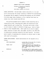
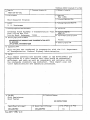
TECHNICAL REPORT STANDARD TITLE PAGE
—
1.^Report No.
/..."'
3.^Recipient's Catalog No.
2.^Government Accession Na.
.IIWA-AR-80-001
S.^Report Date
4.^Title and Subtitle
May 1981
6.^Performing Organization Code
Skid Research Program
7.^Author(s)
,8.^Performing Organization Report No.
J. R. Westerman
10.^Work Unit No.
9.^Performing Organization Name and Address
Arkansas State Highway & Transportation Dept. n.^Contract or Grant No.
HRC-29
Post Office Box 2261
Little Rock, Arkansas^72203
13. Type of Report and Period Covered
12.^Sponsoring Agency Name and Metres..
ARKANSAS STATE HIGHWAY AND TRANSPORTATION DEPT.
P.O. BOX 2261
LITTLE ROCK, ARKANSAS 72203
Final
14. Sponsoring Agency Code
15. Supplementary Notes
This Project was conducted in cooperation with the U.S. Department
of Transportation, Federal Highway Administration
16. Abstract
This report presents the actions taken in the development and
'P.- acquisition of a skid testing unit that would be economical,
efficient, and. safe as well as repeatable and reliable while
the statewide inventory was conducted.^This report also contains specifications and operating procedures.^.
•
17.^Key Words
18.^Distribution Statement
Skid Resistance
Skid Tester
NO RESTRICTIONS
----.^Security Classif. (of this report)
UNCLASSIFIED
Form DOT F 1700.7 (8.69)
20.^Security Classif. (of this page)
UNCLASSIFIED
21. No. of Pages
61
.
22.^Price
TABLE OF CONTENTS
Page
Table of Contents^
2
List of Figures^
3
Chapters
I. Introduction^
A. General^
B.
4
4
Objectives and Scope of HRC-29^5
II. Selection, Acquisition, and Operation of
the Arkansas Skid Testing Unit
A. Evaluation of Skid Testing Devices^8
B. Comparison of Two-Wheel Testing^9
Devices
C. Selection and Acquisition of a Skid ^11
Testing Device
D. Performance of Skid Testing Device^14
E. Modification of Skid Testing Device^16
III. Development of Inventory System
A. General^
23
23
B. Data Collection^
C. Data Storage and Retrieval ^ 25
IV. Coordination with HRC-38 and HRC-40 ^29
V.
VI.
VII.
VIII.
Conclusions^
32
Implementation^
33
References
Appendices
A. Cost
B. Design Criteria and Specifications Towing Truck
C. Specification for Skid Testing
Trailer
D. Specification for SN Computer
E. Operating Procedures for Skid Testing
Trailer
2
LIST OF FIGURES
Figure
Page
1
ST1^(Skid Tester 1)
12
2
Console in ST1
13
3
Component Positioning in Modified
Skid Testing Unit
17
4
Microcomputer in Inventory Unit
18
5
Inventory Unit
18
6
Modified Skid Testing Unit
21
7
Water Pump Compartment
22
8
Diagram of Test Pattern
25
9
Typical Skid Inventory Printout
26
Data Storage and Retrieval System
28
10
3
CHAPTER 1
INTRODUCTION
GENERAL
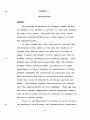
The problem of skidding on slippery roads, as well
as research into methods to prevent it, has been present
for over forty years. Agencies have now fully recognized and accepted skidding as a major hazard in highway transportation.
It was a known fact when this project started that
the average travel speed of vehicles had steadily increased over several years and that this increase in
speed, coupled with higher traffic density per mile of
highway, merely intensified the skidding problem. This
problem had reached such proportions that the Federal
Highway Safety Standard Number 12 required all state
governments to have a program for resurfacing or other
surface treatment for correction of locations with low
skid resistance and high or potentially high accident
rates that could be reduced by providing improved surfaces. The Federal Highway Administration was charged
with the administration of this Standard. They ask that
the state highway departments compile statewide inventories of skid values covering all sections of pavement on
the state highway system.
Prior to the Department's purchase of skid trailers,
. the Arkansas State Highway and Transportation Department
4
did preliminary skid investigations by using the stopping
distance vehicle method. This procedure was slow, expensive, and hazardous; therefore, it was prohibitive to
conduct a continuing inventory of all state highways using
this method. Since skid resistance had become a very
prominent factor in the field of highway safety, the
Arkansas State Highway and Transportation Department
initiated this project in cooperation with the Federal
Highway Administration. The first requirement of this
project was to study various skid testing units, determine
specifications, and either acquire or construct a skid
trailer.
In addition to a literature review, an informational
review was initiated by requesting from various state
highway and transportation departments, Federal, and private agencies, a copy of their plans and costs for construction or purchase of a skid trailer. The Department
received information from twenty-eight states and three
private organizations. The conclusions of this investigation are discussed in appropriate sections of this
report.
OBJECTIVE AND SCOPE OF HRC -29
During the 1960's, skid testing research became a
high priority of various research agencies; Arkansas was
no exception. The Arkansas Highway Department (now named
the Arkansas State Highway and Transportation Department)
5
did some preliminary skid testing using the "stopping
distance vehicle method". Although this method proved
to be adequate for the limited amount of testing performed, the method was too costly, time consuming, and
hazardous. Therefore, this research project, "Acquisition, Calibration and Application of a Skid Trailer",
was begun on July 1, 1970 in an attempt to develop an
economical, efficient, and safe system that could be
used to determine the skid characteristics of highway
pavements in Arkansas.
This goal was to be accomplished by meeting the
following six objectives: 1) acquire or construct a
skid trailer; 2) calibrate the equipment; 3) test
existing surfaces; 4) test and recommend corrective
measures for high or potentially high accident locations; 5) establish minimum frictional values; and 6)
develop methods for application of skid technology on
a statewide basis. As a result of several modifications
to the research proposal and work plan, the modified
project was conducted in four separate phases: 1)
literature review and acquisition or construction of a
skid trailer; 2) establishment of calibration and operation procedures; 3) establishment of a statewide inventory system; and 4) coordination with HRC-38, "Asphalt
Surface Durability and Skid Resistance", and HRC-40,
"Rapid Wear Track".
At the time this project began, the staff anticipated
6
that the following benefits would be realized: 1)
reduced crew size; 2) reduced time required at each
site to conduct each test; 3) reduced cost per test;
4) increased efficiency; 5) improved water delivery;
6) improved uniformity of each test; 7) improved
accuracy; 8) increased mobility; and 9) improved
safety.
Implementation of the results of HRC-29 is the
continuation of the inventory system that was developed
as part of this project. The skid resistance of all
State highways are coded onto magnetic tape and are
updated periodically by the Division of Planning and
Research. This system provides a forewarning of highway sections approaching dangerous limits. Each
District is notified promptly if any section of highway has a serious decline in skid resistance since
previous testing.
7
CHAPTER II
SELECTION, ACQUISITION, AND OPERATION
OF THE ARKANSAS
SKID TESTING UNIT
1971 EVALUATION OF SKID TESTING DEVICES
Since the method of testing has a profound influence
on the value of skid resistance measurements, it was necessary that the Department select the most suitable unit
for Departmental use.
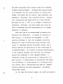
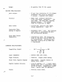
The following table compares the various types of
testers as to their suitability for research purposes and
routine surveys.
SUIT.kFtILITY OF PAVEMENT FRICTION TESTERS FOR ROUTINE USE.
STOPPING
M
PORTABLE
DISTANCE
tTR;T EP.ION
TEST ERS
CARS
TRAILERS
Meaningful measurement
Accuracy of test data
Data display
Test frequency
Operating range
Mobility and maneuverability
Traffic interference
Ruggedness
Hazard to test crew
Recuirrd test crew. minimum
Poor to gobd
Good
Ind ica t ion
Poor
Poor
Good to excellent
Very high
Good
High
Good
Poor to good
Indirectly derived
Poor
Poor to good
Excellent
High
Poor
Very high
3-4
Good to excellent
900
3.506
10.000 to 25.000
100-400
5
1.250
4.200
0.32
Good to excellent
R ecordine
Good to excellent
Good to excellent
Poor to excellent
Low
Good to excellent
Low
Pr“c7.4rernent and operating cost:
Initial, cost. average ($)
Sites tested per day (no.)
Life expectancy (yr)
Malnt. and direct cost per season {$1
Total wages per season IS)
Cost per site tested (S)
15-25
6
50
4.200
3.45
1.250
4.70
* Table from NCHRP Report No. 37
8
The conclusion drawn from the above information was
that "skid trailers" are the most efficient, economical,
and suitable means for determining friction coefficients
of pavement surfaces.
COMPARISON OF TWO-WHEEL TRAILER UNITS
Results from the 1962 Tappahannock Correlation Study
and the Florida Skid Correlation Study were examined to
evaluate the degree of standardization which would be
achieved by skid test trailers that were constructed in
accordance with ASTM Standard, "Test For Skid Resistance
of Pavement Using a Two-Wheel Trailer" (ASTM Designation:
E174-65T). The Department concluded that: 1) many types
of trailers are capable of accurately determining the
coefficient of friction resulting from a steady state skid;
2) good agreement existed among trailers which included
three different types of force measuring systems; and 3)
good repeatability was achieved by the individual trailers.
Even though a trailer might have the following characteristics: 1) good repeatability; 2) test results which correlate with skidding accident frequency or risk of skidding
on all types of pavement surfaces and over the entire speed
range of vehicular traffic; it is understood that frictional
measurements under seemingly ideal conditions are affected
by conditions beyond the control of the operator.
As a result of our analysis, the following ten requirements were incorporated into the design of Arkansas'
9
original tester (ST1):
a)
meaningful measurements
b)
precision of test data
c)
minimum data processing
d)
balanced coverage and test cycle frequency
e)
adequate range of operation
f)
high degree of mobility and maneuverability
g)
minimum traffic interference
h)
structural integrity
i)
economy of operation
j)
comfort and safety of crew
During 1971 several states that had skid-testing
units were surveyed concerning their skid-testing unit.
Based on information from our survey of the states and
the fact that the Arkansas State Highway and Transportation Department was not properly staffed nor had adequate
facilities for the construction of a skid trailer, the
most logical, economical, and desirable alternative was
to:
1.
Requisition the tow truck from the Department's
Equipment Division;
2.
Secure from a local source, a water tank and body
for the tow truck; and
3. Purchase a commercial model skid-testing trailer
and necessary recording and control equipment,
with provisions for the installation and hook-up
of all components by a successful bidder.
10
From the survey information, based on the most common
use and satisfactory performance, a composite tow vehicle
,
for a skid testing unit was characterized. This vehicle
was to have a GVW rating of 10,000 pounds with a V-8 engine
of at least 390 cubic inch displacement, standard cab, 4speed manual transmission, single speed axle, and be capable
of maintaining 65 mph test speeds when loaded.
This same approach was used for determining the most
desirable characteristics of a skid trailer. Most of the
trailers were designed to meet requirements of ASTM E274-65T,
and therefore, were of the same basic design. Since the
trailer design had to meet the ASTM requirements, the only
decisions to be made were which components would be incorporated into the trailer. A detailed list of requirements and
specifications are included in the appendices of this report.
SELECTION, ACQUISITION, & DESCRIPTION OF A SKID TESTING DEVICE
As a result of the information from the Department's survey of states with skid testing systems, previous studies, and
technical reports on commercially built systems, the Department
concluded that the only feasible manner of obtaining a skid
testing system was to purchase a tow vehicle and then request
bids from suppliers of commercially built trailers. Soiltest,
Inc. of Evanston, Illinois was awarded the contract to supply
the trailer, an ML 350-H, and all the necessary instrumentation. (In future references this skid testing system shall be
referred to as ST1.) ST1 was constructed and operated in accordance with ASTM E274.
11
1
;" ••:^•
1::t: •: • •
•^••
'•^•^•
;E:14.41F;
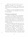
ST1 consisted of three main components (see Figures
No. I and 2): 1) a towing vehicle, which carried a water
supply, a pumping system and the instrument console; 2) a
skid trailer; and 3) an instrument console which is mounted
in the cab of the towing vehicle between the driver's and
passenger's bucket seats. Included in the appendix of this
report are a complete set of specifications, a brief description of STI, as well as a summary of operational
procedures.
ST1 was placed into operation on April 10, 1972.
PERFORMANCE OF SKID TESTING DEVICE
After STI had been in operation for several weeks, it
became evident that ST1 did not have the capabilities or
features that were required to conduct an efficient Statewide inventory program over an extended period of time. (A
detailed description of the inventory program that was developed for Arkansas highways is included in another chapter
of this report.) Some of the problems that were encountered
included: 1) slow data reduction; 2) improper water tank
location on the tow truck; 3) poorly sealed terminal box on
the trailer; and 4) extensive maintenance to ST1.
Of the problems listed above, data reduction was the
most frustrating and serious. As each skid test was run,
the two-channel, strip chart recorder (as shown in Figure No. 2
and discussed in Appendix C) received an electrical input
from the strain gauges in the transducer and then graphically
14
displayed the traction force as a strip chart trace.
Since the data was recorded as a trace, an additional
hour was required to interpret the results to arrive at
an average skid number for each hour that was spent in
the field collecting data. Interpretation of a single
trace by two people often resulted in difference in the
average skid number for a particular skid test. In
addition, storage of the traces for later reference was
impossible for obvious reasons.
The second problem that is listed above also had an
adverse effect on the reliability of the data that was
being recorded. When ST1 was designed, the water tank
was located at the rear of the tow vehicle (see Figure
1), and as the quantity of water in the tank changed,
the height of the trailer hitch also changed, which
meant that the axis of the trailer was rotated so that
it was not parallel to the direction of motion. This
resulted in an error of up to 5 SN for each test.
Another area of concern in relation to the reliability of the data was that the relays in the terminal box
on the trailer were almost impossible to keep dry. Whenever a heavy rain fell or whenever the humidty was high,
the relays would become damp or wet. Several different
methods and materials were used in trying to seal the box;
however, only limited success was achieved. As with any
electronic connection that gets wet, the relays transmitted faulty data to the strip chart recorder.
15
When ST1 went into service on April 10, 1972, its
dependability was suspect. It was in the shop for
repairs as much as it was working. This caused the operational cost per mile to be approximately $0.82 per mile
driven.
Therefore, it is easy to understand why the Department was disappointed in the performance of ST1, and had
the system modified.
MODIFICATION OF SKID TESTING DEVICE
As stated in the previous section, ST1 had several
characteristics which the Research staff decided would
hinder the efficiency and reduce the effectiveness of a
Statewide Inventory Program. ST1 was partially modified
to eliminate these characteristics, to take advantage of
advances in technology, and to reduce the overall cost of
performing skid tests.
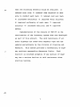
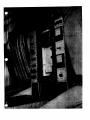
The first modification was made during the fall and
winter of 1974. At that time a DL-12 Data Logging System
(as shown in Figure 3) which was designed and built by
Data System, Inc., replaced the two-channel, strip chart
recorder (as shown in Figure 2). The DL-12 System primarily consists of two components: 1) a SN computer; and
2) a 12-column digital printer. Since the SN computer
analyzed the analog signal from the strain gauges, computed
and printed an average skid number, a significant manpower
16
COMPONENT POSITIONING IN MODIFIED SKID TESTING UNIT
1.
12-Column Digital Printer
2.
SN Computer
3. Memodyne Data Logger
4.
Primary Control Panel
5. Velocity Indicator
6.
Flow Meter
FIGURE 3
17
MICROCOMPUTER IN INVENTORY UNIT
FIGURE 4
INVENTORY UNIT
FIGURE 5
18
savings has been realized in analyzing the data This modified skid testing device was used to develop the procedures
that are currently being used to conduct the statewide
inventory. (These procedures will be discussed in later
sections of this report.) Even though this unit is still
used to check spot locations, a newer, more advanced skid
testing unit was designed and built for the inventory program. Except for this brief statement and Figures 4 and 5,
no other reference will be made to this unit since it was
developed under a different contract.
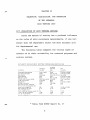
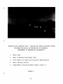
Due to excessive down time which was caused by failures of various components, the trailer was only operational
approximately 50% of the time. The Department was not
satisfied with the trailer's record; so the University of
Arkansas' Mechanical Engineering Department was contracted
to design and construct a skid testing system which conformed to ASTM Specification E274-70. The system (as shown in
Figures 6 and 7) has been in operation since October, 1977,
and has been reasonably reliable in its performance. A
detailed description of the trailer design and construction
can be found in Dr. Jack H. Cole, Mr. James G. Gleason, and
Mr. James L. Dale's report, "The Design and Construction of
a System Utilizing a Trailer to Measure Skid Resistance of
Paved Surfaces", which is available from AHTD or NTIS.
The third modification of ST1 was the installation of
a Memodyne Data Logger (a magnetic cassette tape recorder).
Additional information will be included in the Data Storage
19
Section of this report.
A detailed equipment cost list is provided in Appendix
A of this report. The original skid unit, as well as all
modification costs, are included in the list.
20
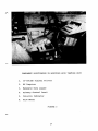
MODIFIED SKID TESTING UNIT: TRAILER AND WATER DELIVERY SYSTEM
DESIGNED AND BUILT BY UNIVERSITY OF ARKANSAS
DEPARTMENT OF MECHANICAL ENGINEERING
1.
Water Tank
2.
Hose to Nozzles from Water Tank
3.
Fifth Wheel for Speed and Distrance Measurements
4.
Water Delivery Nozzle
5. Compartment Containing Water Pumps (Figure 7)
FIGURE 6
21
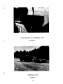
WATER PUMP COMPARTMEF
FIGURE 7
22
CHAPTER III
DEVELOPMENT OF A STATEWIDE SKID INVENTORY PROGRAM
The Statewide Skid Inventory Program that is currently being used by the AHTD's Division of Planning and
Research was developed for the three following reasons:
1) a recognized need to maintain a reliable record of
potentially high accident locations; 2) the need to
provide the Department's maintenance personnel with an
additional method of identifying hazardous locations that
require maintenance; and 3) the Federal Highway Administration's Instructional Memorandum on Skid Accident
Reduction which required that a comprehensive, as well as
continuing, Skid Inventory Program be established by
January 1, 1975.
For the inventory to be of value, blanket type coverage of all highways in the State was required. Several
factors were considered by the Research staff during the
evaluation and development of the Inventory Program: 1)
15,000 miles of State highways were to be inventoried; 2)
10,000 miles of paved county roads and city streets eventually needed to be inventoried; 3) a limited amount of fiscal
resources would be available to purchase, operate and maintain the operation; 4) type, amount, and method of data to
be collected during the testing phase; 5) data storage and
retrieval; 6) complexity of equipment operation during data
collection; 7) frequency of tests; 8) direction of testing;
23
9) routing of tests; 10) number of individuals needed to
operate each phase of the program; 11) rate that data
could be collected; and 12) establishment of specific
reference points so skid numbers could be evaluated for
any given section of highway.
The approach that was selected consisted of a two-man
crew completing the inventory in one county at a time. As a
result of this approach, a realistic time table for completing the skid inventory could be established, maintained and modified if needed. A Research crew tested the
approach and concluded that, in most cases, one week per
county provided more than enough time to complete the skid
inventory in each county. By applying the schedule, approximately 75 to 80 weeks would be required to complete the
inventory, if no major difficulties arise. (Weather and
equipment malfunctions have caused long delays in completing the inventory.) A central location in each county was
selected, and the inventory crew tested to the county line
in a "spider web" type configuration. The inventory began
in Miller County and moved east until the southern counties
had been inventoried. The next row of counties would then
be inventoried by moving toward the west.
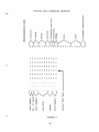
Skid tests are made every 1/2 lane mile in each direction, and the tests are staggered every 1/4 mile (as shown
by Figure 8). Thereby, four tests per mile are obtained.
In the event of a bad test, another will be run immediately
after the bad test cycle is completed. Special tests may
24
also be made on changes of surface type. All skid testing
is conducted in accordance with ASTM Specifications.
Test^Test
Test^Test
1 Mile
FIGURE 8
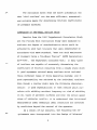
DATA STORAGE AND RETRIEVAL SYSTEM
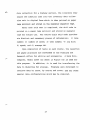
Any discussion of the data storage and retrieval system must begin with a brief discussion of the data that is
collected by the skid inventory unit. An example of the
data is illustrated in Figure 9. As shown in Figure 9, the
data is divided into two categories, a twenty-four digit
identity code and a twelve digit skid code.
The identity code is the name which makes a particular
set of data unique. A complete description of the highway
section is contained within the code. For example, the code
is comprised of nine definitive parameters: 1) district num-
ber; 2) county number; 3) route number; 4) section designation;
5) alternate section designation; 6) direction of data col-
lection; 7) date of data collection; 8) time of data collection; and 9) pavement temperature. Prior to the start of
25
^
^Z
TYPICAL SKID INVENTORY PRINTOUT
a
O
U
0
0
—1^>1
4-)
4-)^a
(n
C
w
4.)
O
0
ic4
E
Q
E-1
0 9 8 4`0 7 2 5 1 0 4 5 0 5 2 2 7 9 1 3 4 5 2 4
`
1 2 0 1 0 0 9 8 4 0 4 4
1 2 0 2 0 0 9 3 4 0 4 2
1 2 0 3 0 0 8 8 4 1 4 3
1 2 0 4 0 0 8 3 4 1 4 3
1 2 0 5 0 0 7 8 3 9 4 4
1 2 0 6 0 0 7 3 3 9 4 4
k^k
U
-
co
2^
1^0
a^a^
41
U
O
O
ki
z^•.-1
z^T1
4)^0
W^1:71^U
W^ 04
El^00^M
FIGURE 9
26
♦-
data collection for a highway section, the inventory crew
inputs the identity code into the inventory data collec
tion unit in digital form which is then printed on paper
tape printout and stored on the magnetic cassette tape.
After each skid test is completed, the skid code is
printed on a paper tape printout and stored on magnetic
tape for future use. The twelve digit skid code provides
six distinct and necessary pieces of information: 1) lane
number; 2) number of lanes; 3) test number; 4) log mile;
5) speed; and 6) average SN.
Upon completion of tests in each county, the cassettes
and paper printouts are forwarded to the Planning and
Research office for editing and processing. A Wang MiniComputer, Model 2200T (as shown in Figure 10) is used for
this purpose. In addition, it is used for transferring the
data to diskettes for storage. Programs were developed to
retrieve data by route, by county and route, and any other
special data configurations which may be required.
27
DATA STORAGE AND RETRIEVAL SYSTEM
FIGURE 10
If
28
CHAPTER IV
COORDINATION OF HRC-29, "SKID PROGRAM" WITH HRC-38,
"ASPHALT SURFACE DURABILITY AND SKID RESISTANCE"
AND HRC-40, "DESIGN, CONSTRUCTION, AND EVALUATION
OF A RANDOM PATH RAPID WEAR TRACK"
Two projects, HRC-38 and HRC-40, were already underway when this project was revised in 1975. Both of these
projects dealt with topics which were either directly or
indirectly connected with skid resistance. Therefore, it
was logical for the work activities of all three projects
to be coordinated throughout the life of each project.
"HRC-38 was a four-year investigation of the durability
and skid resistance of existing asphalt concrete hot mix
pavements. The study included field and laboratory evaluation of the polish characteristics and stripping resistance
of 18 most commonly used mineral aggregates in Arkansas.
Aggregate polishing was accomplished by a small circular
wear track that was designed to polish 12 Marshall size
specimens at one time, with in-place specimen frictional
measurements obtained by a British Portable Tester. The
laboratory work included tests of aggregate cast in polyester, Marshall specimens, and pavement cores. The asphalt
mixtures were evaluated for their Marshall stability and
immerson-compression retained strength. The principal findings are as follows: 1) the field tests results indicated
a good correlation between SN40 and BPN values; 2) the laboratory tests yielded a good correlation between the Texas
29
polish value from the British wheel and the Arkansas polish
value from the accelerated circular track; 3) a good correlation was obtained between the BPN (field) value and the
Arkansas polish value (laboratory); 4) polish tests on cores
indicated that most cores had a higher polish value than was
shown from the parent coarse aggregate in the Marshall
polish test (the difference in these values was attributed
to the fine aggregate that was used in the actual paving
mixture); 5) the data indicated that the Arkansas accelerated
polish test results on asphalt mixtures can be used to estimate minimum SN40 values of the mix in thepavement". 1
Dr. Miller Ford of the University of Arkansas, Department of
Civil Engineering, conducted the research for the Department,
and any additional information is available from Dr. Ford,
the Department, or the HRC-38 Final Report, "Asphalt Surface
Durability and Skid Resistance", which was published in 1978.
HRC-40 was to be a fifty-four month study to determine
the aggregate's influence on the wear characteristics of
asphalt concrete hot mix and Portland cement concrete pavements which is one variable that does influence skid resistance. To accomplish this task, Dr. Jack Cole, Mr. James
Gleason, and Mr. Jack Helms of the University of Arkansas'
Department of Mechanical Engineering designed and constructed
a random path rapid wear track which would accelerate the
Ford, Miller C., Jr., Asphalt Surface Durability and Skid
Resistance - Investigation, Civil Engineering Department,
University of Arkansas, Final Report, March 1978.
30
aggregate wear. A final report on the design and construction of the wear track was published in August, 1975. Due
to several serious problems in the hydraulic system, the
system was modified by Dr. Cole and Mr. Gleason. The modified rapid wear track will be discussed in the pending
final HRC-40 report. Operational problems with the wear
track prevented coordination of work activities with this
project.
31
CHAPTER V
CONCLUSIONS
1)
The initial skid testing unit was adequate for
developing and testing procedures to be used in the Inventory Program, but was not sufficient to implement the
Inventory Program.
2) A newer and improved skid testing unit is recommended to implement the Inventory Program.
3) The procedures developed for collecting, storing,
and analyzing skid data have proven to be excellent in
meeting the Department's needs.
4)
The skid Inventory Program has improved the
Department's method of determining priorities for overlaying State highways.
32
CHAPTER VI
IMPLEMENTATION
The Statewide Skid Inventory Program that was developed as part of this research project has been incorporated
into the Department's overall Inventory Program of streets
and highways. The initial Skid Inventory Program has been
completed, and the results have been used to identify highways or portions of highways where work is needed to correct
deficiencies. As changes to data collection and storage
procedures are needed, a modification of skid inventory procedures is made.
33
BIBLIOGRAPHY
1. McCullough, F. F. and Hankins, K. D., "Development of
a Skid Test Trailer", Texas Highway Department,
April, 1965.
2.
Stone, J. and Gulden, W., "Skid Resistance of Highway
Pavement Surfaces", Georgia Department of Transportation, June, 1974.
3. Ford, M. C., "Asphalt Surface Durability and Skid
Resistance", University of Arkansas, March, 1978.
4.
Cole, J. H.,
Design and
Trailer to
Surfaces",
Gleason, J. G., and Dale, J. L., "The
Construction of a System Utilizing a
Measure Skid Resistance of Paved
University of Arkansas, January, 1976.
5.
Csathy, T. I., Burnett, W.C., Armstong, M.D., "State
of the Art of Skid Resistance Research", Highway
Research Board Special Report 95, 1968.
6. Beaton, J.S., "Providing Skid Resistant Pavements",
Transportation Research Board Record 622, 1977.
7.
"Skid Resistance", National Cooperative Highway
Research Program Synthesis of Highway Practice
No. 14, Highway Research Board, 1972.
8. Giles, C. G., Sabey, B. E., Cardew, K. H. F.,
"Development and Performance of the Portable SkidResistance Tester", STP 326, American Society for
Testing and Materials, 1962.
9. Hankins, K. D., "A Program for Reducing Skidding
Accidents During Wet Weather", Transportation
Research Board Record 622, 1977.
10. Gramling, W. L. and Hopkins, J. G., "Skid Resistance
Studies: Aggregate-Skid Resistance Relationship as
Applied to Pennsylvania Aggregates", Pennsylvania
Department of Transportation, May, 1974.
.
11.
Stocker, A. J. and Albert, J. W., "Comparison of the
Ohio State University and Penn State University Skid
System Water Nozzle", Texas Transportation Institute,
August, 1977.
12. Stapler, W. T., Stone, J. S., and Chase, H.D., "A Skid
Resistance Study of Georgia Pavements", Georgia Highway Department, December, 1970.
13. Rushing, H. B., "Skid Resistance Study", Louisiana
Department of Highways, October, 1968.
14. Mullen, W. G., Whitfield, J. K., Gibson, D., Cahoon,
T., Dixon, W., Robinson, J., "Surface Wear and Skid
Resistance Properties for Portland Cement Concrete
Pavements", North Carolina State University, May,
1974.
15.
"Highway Skid Resistance", ASTM Special Technical
Publication 456, American Society for Testing
Materials, October, 1968.
16.
"An Analysis of the Literature on Tire-Road Skid
Resistance", ASTM Special Technical Publication 541,
American Society for Testing Materials, July, 1973.
17. Walter, W. C., "Skid Resistance Study", Louisiana
Department of Transportation and Development, June,
1977.
18.
Bigelow, N., "Skid Trailer Construction", Maine State
Highway Commission, November, 1969.
19.
Sandvig, L. D., Macgregor, L. M., and Shaffer, R. K.,
"Development and Results of a Skid Research and Road
Inventory Program in Pennsylvania", Pennsylvania
Highway Department, August, 1968.
20. Ganung, G. A., "Development and Implementation of a
Skid Test Program in Connecticut", Connecticut
Department of Transportation, April, 1971.
21.
"Revised Skid Code Manual", Texas Highway Department.
APPENDIX
APPENDIX A
COST
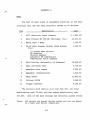
The cost of each piece of equipment contained in the skid
inventory unit and the data retrieval system is as follows:
Description^
Item
Cost
1^1972 Chevrolet Truck Chassis ^$ 3,852.00*
2^Skid Trailer ML 350-EX (Soiltest, Inc.) ^23,230.00
3^Water Tank & Body^
1,700.00
4^DL-12 Data Logging System (Data System ^3,440.00
Inc.)
12 Column Data Printer
SN Computer
Digital Readout
Automatic SN Computation
Push-Button Print Command
22,400.00
5
Skid Trailer (University of Arkansas)
6
Body and Water Tank
1,759.00
7
Memodyne Data Logger
2,493.00
8
Memodyne (Installation)
1,030.00
9
Wang 2200T
11,663.00
10^Printer 2221W^
5,085.00
11^Floppy Diskette^
6,295.00
The original skid testing unit cost $28,782; the first
modification cost $3,440; and the second modification cost
$27,682, Cost of the data storage and retrieval system (Items
*Note: All prices are actual dollar values and are not based
on a base year dollar comparison.
A-1
8, 9 and 10) was $23,043. Funding for the second modification
and data storage and retrieval system was through the Arkansas
Governor's Office of the Coordinator of Public Safety.
Due to equipment failure, the operational cost of the
skid testing unit has averaged $0.82 per mile. All cost of
operating and maintaining the unit was included in determining the operational cost.
APPENDIX B
DESIGN CRITERIA AND SPECIFICATIONS
A. Towing Truck:
Information from 28 states was investigated to determine the type,
size, make and other pertinent data on tow trucks currently in use. It
was found that a wide variety of vehicles from light station wagons to
heavy trucks are currently being used. Some states perferred to have a
light weight vehicle with maximum horsepower engine in order to achieve
test speeds rapidly and with a minumum of effort. Others, perferred
the heavy trucks which were more cumbersome to handle, accelerated more
slowly, but maintain a constant speed during the test because of greater
mass.
The states using the lighter weight trucks did not indicate any
safety problems due to undesirable swaying, even though some reports had
mentioned this as a reason for selection of heavier units. After considering the various possibilities, it is proposed that we use a one-ton
truck powered by a V-8 gasoline engine, standard cab, manual transmission,
single speed rear axle and other special equipment necessary to control
and operate the skid-trailer. Detailed specifications include:
1. Capacity: Manufacturer's gross vehicle weight rating of 10,000 lbs.
2. Net Design Payload: Minimum of 5,000 lbs.
3. Wheelbase: Shall be at least 125 inches and no more than 133 inches.
4. Engine: Shall be an eight cylinder model of not less than 390
cubic inchs displacement and develop not less than 225 net horsepower at manufacturerts rated speed. Shall be eq4pped with
a mechanically operated tachometer. The engine shall have sufficient output, in conjunction with the selected transmission
and rear axle ratio, to maintain 70 mph when testing on a paveB-1
ment surface having a skid resistance of 75 SN and when fully
loaded (i.e., full crew, water tank filled and required load
on trailer).
5. Cooling System: Shall be equipped with heavy-duty radiator to
provide adequate cooling.
6. Transmission: Shall be 4-speed heavy duty synchromesh.
7. Front Axle: Shall be solid "1" beam-type with a rated capacity
of not less than 3,500 lbs.
8. Rear Axle: Manufacturer's rated capacity not less than 7,200
lbs. Single speed with dual wheels and shall be capable of a
top test speed of at least 70 mph.
9. Types of Wheels: Seven only steel, disc, with proper rims for
tire equipment furnished. Not less than the standard SAE specified tire chain clearance of 1.65 inches shall be maintained
between dual rear tires and between inside dual tires and springs
or other chassis parts.
10. Tire Equipment: 7.50-16 8-ply rating, tube-type, same size all
around, dual in rear. One spare shall be supplied mounted on
spare wheel.
11. Brakes: Air over hydraulic.
12. Steering. Gear: Equipped with hydraulic power assist.
13. Cab: Manufacturer's standard type cab, steel enclosed, with
two doors. Two bucket seats having no less than 19 inches
between them.
The following items, supplementing if necessary those items already
cataloged as standard cab equipment, shall be furnished and in place:
a. Air conditioning: Deluxe factory air conditioner (necessary to
control instrument temperature and dust).
B-2
b. Deluxe fresh-air heater with windshield defrosters.
c. Two (2) outside rear view mirrors (West Coast Jrrs.).
d. Dual, windshield washers
e. Two (2) arm rests
f. Dome light
g.
Floor mat and headlining
h. Directional lights
i. Warning lights
14. "Electrical System: Shall be a 12 volt system with a two belt
driven 65 amp heavy-duty alternator with built-in silicon
rectifier and matching regulator. Wiring shall be adequate to
handle full output of selected alternator.
Two (2) heavy-duty batteries of not less than 66 plates,
70 amp hr. shall be furnished. Extra 12 volt battery shall be
installed for furnishing power to the recorder and other systems
through a frequency controlled solid-state inverter.
15. Gasoline Capacity: Not less than 30 gallons. (Location of
rupture proof tank shall be outside of cab.)
16. Body: Bare chassis on rear.
17. Accessories and Special Equipment:
a.
Substantial front bumper (heavy duty steel attached to frame).
b. Heavy duty suspension
c. Jack - 8 ton capacity
18. Water Tank and Body: Capacity of water tank shall be at least
60 cu. ft. Baffle plates of the same size shall be inserted to
divide the tank into four equal compartments to prevent turbulence
and load shift when truck is in motion. All interior surfaces
shall be coated for corrosion resistance. A two (2) inch shutB— 3
off value will be installed to control water flow from tank.
Manholes at the top of the tank will provide access for cleaning the tank interior. Hinged cap will be used for filling
purposes. (See sketch of tank for more details). The final
design will be completed after determining which tow truck is
obtained. Basically, the outside dimensions will be approximately
60 x 102 x 24 inches with steps 8" wide on each side.
19. Power take-off for water pumps - The power take-off on truck
shall deliver approximately.20 horsepower, 1300 RPM at 40 miles
per hour. The power take-off shall be set up for speed proportional to the rear wheel speeds and not proportional to engine
speeds. (Note - a Chelsea type PY-41R-C3E, is normally used on
F-600 Ford with 5-speed forward transmission.)
APPENDIX C
ARKANSAS
STATE HIGHWAY DEPARTMENT
Division
of
Planning and Research
SPECIFICATIONS
for
Skid Testing Trailer
Project No. HRC-29
Skid Testing Trailer:
1. General - Information from 26 State Highway Departments on design
and specifications of their skid testing trailers has been reviewed
and analyzed. We found that many of these trailers are of the same
basic design but have minor differences as necessitated by the needs
or desires of each state. After considering the various possibilities
available, it is proposed that the unit consist of a two-wheel towed
trailer incorporating a water laying system for spreading water under
the tires, a braking system for applying the braking action, strain
gauge bridges (transducers) used in measuring skid resistance, and
pavement skid-test tires. The testing unit must be designed to meet
all requirements of ASTM-E274-65T (latest revision).
2. Trailer Specifications - Detailed specifications will include
the following:
C-1
The trailer shall be a two wheel side by side design of rugged construction, the vertical center of gravity shall be less than 22 inches
above the tire-road interface. The distance between the center line
of the wheels shall be 60 + 5 inches. The tow hitch shall be midway
between the wheels transversely and 100 inches longitudinally ahead
of the axle center line. It shall be as low vertically as practicable
and in no case higher than the wheel center line height. A hinged
stablizing strut with a caster shall be provided for supporting the
trailer near the hitch point when it is uncoupled from the towing
vehicle.
The trailer design shall be such that the service load on each
wheel will be 1085 pounds + 25 pounds and a down load of from 100
to 200 pounds will result at the hitch point.
The trailer axle shall be such that shoe-brakes can be accommodated.
The wheel suspension shall be such that both springing and shock-strut
damping will be provided.
The shoe brakes shall be hydraulically actuated with air over the
hydraulic system. They shall be capable of locking either or both
wheels in 11 second holding for the duration of the test (normally
2 seconds) and releasing the brakes in 3/4 second. Provisions must
be made so that either the left wheel or the right wheel can be locked
independently or both may be locked simultaneously. Brakes will be
automatically applied during test through manually preselection on
the selector switch. Torque developed by braking action is sensed
by two balanced bridge strain gLge systems, one at each wheel of the
trailer, mounted on aluminum torque tubes placed concentrically around
the trailer axle inboard of each wheel. Output from these strain gauges
feeds to the electronic control and recording system. Measurement of
braking action torque curve expressing the skid-resistance force exerted
by the tire-pavement contact.
C-2
Provision shall be made to provide an interconnection between
the towing vehicle brakes and the trailer brakes so that they will
be actuated simultaneously during cross country travel when testing
is not in progress.
The tires shall be the standard tire for pavement tests, ASTM
specification E-249. Two spare wheels complete with rims, tires and
valve stems shall be mounted on the trailer.
A safety chain must be provided at the trailer hitch that is capable
of holding the trailer in case of hitch failure. Fenders will be
provided for the wheels of the trailer. A removable protection cover
for the trailer will be provided. Running lights and safety lights
should be provided as required by Arkansas and Federal Safety laws.
Easily operated disconnects shall be provided between the trailer
and the towing vehicle for the water, air and electronic circuits.
Spray nozzles shall be mounted on the trailer and connected to
the water supply on the towing truck with flexible hose so that water
can be sprayed in front of the test tires, either right or left or
both at the same time. They must be so mounted that they can be
raised when not being used and will swing upward if they should hit
any unexpected object on the pavement to protect them from damage.
Flexible connections are to be provided where necessary to prevent
stresses from being transmitted to the pump or valves.
The nozzle configuration shall be such that high velocity water
jets are directed toward the pavement surface at an angle that will
produce a minimum splash and that water is not applied directly to
the tread of the test tire. The water layer thickness shall conform
to specifications in ASTM-E274 (latest revision).
C-3
The suspension system shall consist of coil springs and shocks
adjusted so that when the trailer is properly loaded and level the
wheel center-line height is never lower than the tow hitch.
C. Recording Instrumentations:
The instrumentation necessary to control and record all phases of
skid testing shall include the following major components: control head
(including the timer); instrument panel; two channel recorder; water
pumps; skid trailer instrumentation (including the strain gauge bridges).
A solid state timer shall be provided so that the driver of the towing
vehicle after making the proper settings can throw one switch and all
the equipment necessary to be actuated during a test will be actuated
in the proper sequence and for the proper duration. The proper sequence
shall include all phases of skid test--application of brakes, release
of water, control of recording devices--programmed through custom-designed
multiflex timer with vernier controls for pre-selection of automatic
timing. Automatic timing shall be accurate to + 1/100th second on vernier
control. The recorder sensitivity shall be at least 10 my input for
full scale deflection.
The strain in the braking system will be measured by strain gauges
(transducer) mounted on the aluminum torque tube concentric to each axle,
that is between the brake drum housing and axle housing. Output from
the strain gauge bridges with a regulated DC power supply is fed to the
two - track recorder. The speed will be obtained from a DC electrical
tachometer generator that is driven by a take off from the towing vehicle's
speedometer driver.
The recorder shall be a specially modified two-channel pressurized
C-4
ink recorder with two event markers. Speed of response shall be such
that not more than one second is required for full scale deflection.
All controls are preset. A dual chart drive allows use of the recorder
during test operation or in static condition. During tests, the chart
shall be driven at a speed proportional to the tester speed by a speedometer-cable.takeoff which is energized by a solenoid clutch--assuring
that paper is consumed only during test cycles. When the skid tester
is not in operation a motor. drive can be used to move the charts for
static calibration and testing. A third pen marks a reference pulse on
the chart, as the last event in the sequence of actions comprising one
test. The reference pulse shows reference calibration of the output
obtained and also the speed at which the test was made.
The instrument console will be mounted between the driver's and passenger's custom bucket seats in truck cab. It will house the main fuse,
ammeter, voltmeter, and recorder (timer is in a separate, tamper-proof
cabinet). Also, included will be circuit lights for the tester, timer,
water system and brakes and manual control switches to start, defeat,
and stop the test sequence and select right, left, or both wheel brakes.
Console will be designed to allow installation of additional, expanded
circuitary and more controls and instrumentation.
D. Electrical System:
The electrical power for the recorder and other systems will be
supplied by a frequency controlled solid - state inverter mounted in the
vehicle cab and powered by a separate 12-volt battery system. When the
test system is in operation, provisions will be made to disconnect the
power-supply battery from the truck electrical system, to assure that
the test system receives nonfluctuating power. Provision will be made
to tie the power supply battery into the trucks electrical system during
the time the recorder is not operating.
E. Water Pumps:
The water pumps are to be a positive-displacement type, that delivers
water to the water-laying system, proportional to the forward vehicle
speed. The pump unit is mounted in the towing truck beneath the water
tank.
F. Other Requirements:
The instrumentation system shall conform to the following overall
°
requirements at ambient temperatures between 40 and 100 F.
Overall system accuracy^3% of full scale
Time stability 10 hours minimum
The exposed portions of the system must tolerate 100% relative humidity
and all other adverse conditions such as dust, shock, and vibrations •
which may be encountered in highway operation.
The vehicle speed measuring instruments shall provide an accuracy
better than 0.2 mph over the expected range of operation.
The instrumentation must be capable of operating under the vibration
conditions normally encountered in the towing vehicle. This will require
rugged construction and ability of the marking system to operate properly
under vibration.
RECOMMENDATIONS
The following recommendations are based first, on the needs of the
Arkansas Highway Department as compared to the budgetary resources avail..
able, and secondly, on the vast experience of several states engaged in
skid-testing activities. Therefore, we recommend that:
A. The Equipment Division procure a tow truck that meets the specifications contained in part III of this report.
B. The Equipment Division obtain and install a combination water
tank and body on the tow truck. (Specifications in part III).
C. The skid-testing trailer and associated equipment needed for
a complete testing unit be obtained from a commerical source.
D. The successful bidder, furnishing the skid-testing trailer,
shall install all equipment required on tow truck and trailer, calibrate and check out the completed unit. Items c and d will be
awarded as one contract.
APPENDIX D
ARKANSAS STATE HIGHWAY DEPARTMENT
Division of Planning and Research
Specifications
for
Skid Number Computer and Printer
GENERAL DESCRIPTION; The skid number computer and printer is to be used
with an existing skid test trailer conforming to ASTM-E274-65T specifications.
The equipment must be capable of receiving and processing raw data obtained
from strain gauge torque transducers or from a modified Gould Brush two
channel strip chart recorder model Mark 220.
The specified equipment must be capable of rapid acquisition and recording friction data, calculating skid numbers and displaying the skid
numbers digitally and in printed form. The printer must accept at least
ten (10) columns or digits of information through preset inputs by thumb"—, wheels or other acceptable means, These inputs will be used for highway
number, direction of travel, date, lane number, log mile or any other bits
of predetermined information selected by the system operator. The printer
must be capable of reproducing this information an infinite number of times
until reset by the operator.
GENERAL SPECIFICATIONS: General specifications for the equipment are as
follows:
Power Requirements^: 115-120 VAC. 60 Hz sine wave, 40 watts
maximum during printing,
Signal Input
Dimensions
Single ended analog raw force data or
unprocessed strain gauge transducer SN
data. Brake signal nominal + 12 VDC
Cal 1.0 amp.
: The unit(s) must be small enough to mount
in the vehicle for compatible installation
with existing equipment and instrumentation.
D-1
Weight^
: No greater than 30 lbs, gross.
PRINTER SPECIFICATIONS:
Data Columns
: 12 per line consisting of; 10 columns
thumbwheel data entry by operator.
2 columns - computed skid number.
Printout
: Paper tape, pressure sensitive,
3,375 inch width, characters - .110
inch high, .100 inch wide, spacing
between columns - ,275 inches.
(Over 40 lines/foot of tape)
Data Format^
Conversion Time,
Analog to Digital
Print Rate Versus
Temperature
: 1-2-4-8 BCD, positive true logic.
Column suppression - logic "1".
: Thumbwheel data - none. Raw traction
force data or unprocessed SN data 400 milliseconds maximum,
: Intermittent duty, 100 consecutive
lines at 25% duty cycle @ +20°C for
2,5 lines/second. Continuous duty,
100% duty cycle @ 0°C to +40 ° C for
1 line/second.
COMPUTER SPECIFICATIONS:
F
SN = ^ x 100
Computation Format
w
[h
1
•
Input Impedance
: Greater than 100 K Ohms.
Input Polarity
: Positive. Single ended analog.
Front Panel Digital Display
: Skid Number. Display remains in
memory until reset,
Digital Readout Accuracy
: 0,5% of reading + or - 1 least significant digit over a temperature range
of 0°C to +40 0 C. Temperature coefficient - better than 150 ppm/deg.C.
Timers^
: Strictly solid state,
D-2
Timing Sequencing ^: Sampling to begin 0,5 seconds after
brake initiation. Sampling period 1.0 seconds.
Timing Accuracy^ : At least 0.5% of longest timer,
APPENDIX E
SOILTEST, INC.
2205 LEE STREET
EVANSTON, ILLINOIS U.S.A.
SUBSIDIARY OF CENCO INSTRUMENTS CORPORATION^
•
TELEPHONE 312/8694500
^
•^CABLE: SOILTEST, EVAKSTON
OPERATING INSTRUCTIONS
DATE
DESCRIPTION
HOOEL
ML-350E &
MI-350H
SKID TESTING TRUCK AND TRAILER
4-5-71
SEC. 1-1 - GENERAL DESCRIPTION
The Soiltest Skid Tester is designed for the purpose of measuring the
amount of resistance to skidding presented to tires by road surface
material.
Two models are available:
MI-350E with electric drum brakes
MI-350H with air over hydraulic disc or drum brakes
r
-
In general, this instruction manual is applicable to either model,
except where specially noted.
SEC. 1-2 - METHOD OF TESTING
A specially instrumented two wheel trailer is towed behind a truck.
On each wheel is a strain gauge transducer. The transducers measure
the amount of torque exerted on the axle of the trailer under lockedbrake conditions on wet pavement.
The towing vehicle carries the water supply for wetting the pavement
and all necessary instrumentation. The instrumentation records test
results on a strip chart recorder, and it also provides complete control
of the tests being conducted.
SEC. 1 3
-
-
PHYSICAL DESCRIPTION OF EQUIPMENT
The Soiltest MI-350 is comprised of three basic components: (1) the
towing truck, (2) the skid trailer, and (3) the instrument console.
-
The truck carries the water supply and pumping system and the instrument
console.
The trailer carries the torque measuring strain gauge transducers,
water laying nozzles for pavement wetting, and water and brake control
solenoids.
E-1
EIGINEERING TEST EQUIPMENT FOR SOILS, CONCRETE, BITUMINOUS PRODUCTS 1. CONSTRUCTION MATERIALS
Operating Instructions
MI-350E and MI-350H
Page 2
The instrument console is located between the drivers' and passengers'
seats, inside the cab of the towing truck. This console contains all
controls for the complete test sequence. Once initiated by the START
button, the test sequence is automatic, being governed by a built-in
timer. The console also contains the force measuring recorder.
The truck has a manual control for the trailer brakes for use on the
highway when not testing. The truck and trailer lights conform to ICC
regulations. The towing truck is equipped with flashing safety lights
as standard equipment.
An electronic speed meter is located on the dashboard of the truck to
provide precise speed indication.
SEC. 1-4 - TYPE OF INDICATION OF SKID RESISTANCE
The instrument console in the truck cab is equipped with a two-channel
recorder as standard equipment. The torque required to slide the skid
tire on a wetted pavement is read directly on the chart as poundstorque when the system is correctly calibrated. On most models, the
left recorder channel records the torque developed by the left skid
tire, and the right channel records the torque developed by the right
skid tire. On some models, the left channel is used to record vehicle
speed and only the right channel is used to record torque.
SEC. 1-5 - THEORY OF OPERATION
The Soiltest Skid Tester basically consists of a. special trailer towed
by a truck. At a preselected test speed, water is applied to the pavement to be tested ahead of one or both test wheels (as selected) and
the brakes on the trailer are locked. The resultant torque is recorded
on a strip-chart recorder in the instrument console. The water flow
applied to the pavement•is designed to leave a film of water .020 inch
.005 inch thick, regardless of vehicle speed. The torque measured
is sensed by balanced-bridge strain gauge transducers mounted on special
torque tubes. These tubes are mounted concentric to the axles of the
trailer. All test functions are automatically controlled by the timer
in the instrument console.
The timer is set so that the test sequence occurs in this order: (1)
Start recorder. (2) Start water flow. (3) Calibrate pulse is recorded.
(4) Brakes lock for 2 seconds. (5) Brakes release. (6) Water is turned
off. (7) Recorder stops. (8) Timer resets and the unit is ready for
the next test.
SEC. 2-1 - PREPARATION FOR OPERATION
Before any instrument preparations are made, a walk-around inspection
of the truck and trailer should be made. Check all tires for cuts and
E -2
t
Operating Instructions
M1-350E and ML-350H
Page 3
for correct air pressure. Pay particular attention to the pressure
in the skid tires; THIS IS IMPORTANT! Correct pressure is 24 pounds
and this pressure must be maintained. If skid tire pressure is incorrect, the recorded torque readings will be wrong.
Make certain that the trailer hitch is fastened tightly and that the
safety chains are properly fastened. Finally, be sure that all electrical, water and any other connections are properly made.
Fill the water tank on the truck with CLEAN water. Be sure the drain
valve on the truck is closed: Turn the instrument console on and allow
at least 15 minutes warmup time before attempting any testing.
SEC. 2-2 - CONTROLS AND THEIR FUNCTIONS
The instrument console is the "heart" of the skid tester. It controls
all functions of the unit. Located behind the passenger seat is a
high-quality Topaz brand inverter which is used to convert twelve
volts DC to 120 volts 60 Hz AC. This voltage is used to provide power
for the timer and the strip chart recorder. The inverter used is
capable of providing 250 watts of power continuously, but only a fraction of that amount is used in the skid tester. The inverter is conservatively rated and operated and can be expected to provide many
years of service, unless it is abused.
Inside the locked instrument cabinet, toward the rear, is the timer.
The timer controls the time of each function of the test and the time
of the overall test sequence. The timer may be easily reset to meet
any special requirements by simply changing the setting of the on and
off time of each function, as labeled. Use caution if you are changing the water and/or brake setting so that you do not inadvertently
skid the tires on the pavement before water is applied!
On the passenger side of this same compartment is the primary instrumentation fuse block. The 60-ampere fuse protects all of the instrumentation. The fuse should be removed whenever ANY work is being done on
the console, or if any panels are to be removed.
In describing the controls, it will be assumed that the console is
being viewed from the drivers' side.
Controls on the left-side panel (at the drivers' side) are as follows:
START: Pressing this switch begins the test cycle. Once a test cycle
is started, all functions of the skid tester are automatically
controlled until the cycle is completed.
DEF'E'AT; Pressing this button will stop a test sequence at any point
in its cycle. This function might be used under such conditions
as bad roads, traffic hazards, etc.
Operating Instructions
ML-350E and MI-350H
Page 4
WHEEL SELECT: This switch is used to determine which brakes are to
lock: right, left or both. It also feeds water to the proper
wheel(s). Any of the three settings may be used.
ADVANCE CHART: This pushbutton allows the operator to run the chart
forward without initiating a test cycle. This function is
very useful as an aid in calibration and balancing.
CHECK CALIBRATE: This button provides a calibration pulse and is used
as a reference in calibration. Use of this function will be
discussed further in the calibration procedure.
ZERO RECORDER: Pressing this button removes all signals from the re-
corder inputs and allows the operator to balance the recorder
to zero. When zeroing the recorder, use the position control
on the recorder for each channel, as marked.
LEFT AND RIGHT BALANCE: These knobs allow the operator to balance
the two strain gauges to zero.
LEFT AND RIGHT F.S. (FULL SCALE): This knob adjusts the height of the
calibrate pulse and is used to ensure proper calibration. This
is explained in the section on calibration procedure.
In the center of the console is the strip chart recorder. In normal
road testing sequences, the sensitivity switches should both be set at
the 1 my positibn and the chart speed should be set at 25 mm/sec.
Under static test or calibration checks, a chart speed of 1 or 5 mm/
sec. can be used to conserve chart paper.
SEC. 3-1 - TESTING ON THE ROAD
To operate the Soiltest Skid Tester on the highway, perform the following operations: Be sure that the hitch, safety chains and all supply
connections are securely fastened. Close the drain valve on the water
supply tank on the truck and fill the tank with CLEAN water through the
filling port at the top-rear of the tank. Open the main valve, which
is also located on the water tank. Start the engine of the truck and
turn on the POWER switch on the console. Be sure to allow at least
fifteen minutes warmup time for the equipment to stabilize.
When warmup time has elapsed, press the ADVANCE CHART and ZERO RECORD
buttons at the same time and zero both channels of the recorder using
the left and right POSITION controls on the recorder itself. Now release the ZERO RECORD button and re-zero the pens, using the left and
right BALANCE knobs on the console. Now press the CHECK CALIBRATE
button and adjust left and right F.S. knobs to read the number determined in the calibration of the tester.
Next, depress the clutch and, at a dead standstill, pull out the PTO
knob on the center of the firewall.
E -4
Operating Instructions
MI-350E and MI-350H
Page 5
NOTE: In trucks with automatic transmissions, this operation is performed automatically by the timer through a magnetic clutch.
The tester is now ready for operation and you may drive to your test
site.
When you have reached the highway to be tested, be sure you have the
WHEEL SELECT switch set to the desired position. Attain the chosen
test speed (usually 40 miles per hour per ASTM E-274-65T, par. 5.1)
and press the START button. All functions of the test will be performed automatically.
At intervals during your test sequences, it is wise to re-check the
zero of the recorder, the balance of the bridge(s), and the height of
the calibrate pulse. This will eliminate the possibility of drift in
the equipment or inadvertantly moving the wrong knob, which could give
erroneous results.
SEC. 3-2 - OPERATING PRECAUTIONS
1. Be sure that the truck is NOT moving when you engage the PTO!
2. Remove the main fuse in the console when any work is being done
in the console or if panels are removed.
3. Do NOT operate the truck with the PTO and pumps running unless the
main valve is in the OPEN position and the water tank is full.
4; The drain valve should be opened on the tank and the pumps and
solenoid valves in the event of freezing weather. This is discussed further in the storage section.
5. When testing, be sure you have an adequate supply of water.
SEC. 3 - 3 - CALIBRATION OP MODELS RECORDING TORQUE ON BOTH RECORDER
CHANNEIS
It is recommended that the Soiltest Skid Tester be calibrated using
the Soiltest model MI-360 Dynamic Skid Calibration Unit, which includes a Soiltest 1000 lb. capacity proving ring with a dial indicator,
a proving ring calibration chart, fine thread screw, ratchet wretch,
wheel block and complete instructions.
Position the truck and trailer as level as possible. Jack up the trailer
and position the calibrator under the left wheel. Place a block of
equal height under the right wheel. A wood block is preferable to a
concrete or similar block as it is not likely to break. Lower the
trailer onto the calibrator and block. Use the jack to level the trailer hitch. Zero the calibrator.
E- 5
S.
Operating Instructions
MI-350E and ML-55011
Page 6
Start the truck and turn on the equipment. Allow the normal 15 minute
warmup period so the equipment has time to stabilize. Set both recorder sensitivity switches to the 1 my position. Press the ZERO RECORD
button and adjust both position controls on the recorder so the pens '
are at zero. Release the ZERO RECORDER button and again zero the recorder, this time using the left and right BALANCE controls on the control console. The F.S. controls should both be at approximately their
mid-range positions at this time.
Lock the trailer brakes, using the toggle switch LOCK BRAKES, located
inside the locked compartment on the drivers' side. Add the desired
wheel load with the calibrator in 100 pound increments, and, with the
left SENSITIVITY control on the recorder, adjust the pen to read one (1)
major division for each 100 pounds of wheel load. Be sure to tighten
the lock nut on this control when finished with calibration.
Now release the trailer brakes and press the CALIBRATE button. Make a
note of the reading obtained. This reading is now the calibrate reference number and it is used to indicate that the equipment is working
properly and that the unit is in calibration.
To calibrate the right wheel, repeat the above procedure on that wheel.
When both wheels are calibrated, the unit is ready for road service.
SEC. 3-Q - CALIBRATION OP PIALuNtzm SPEED/LEFT AND TOR UE• RIGHT
Position the truck and trailer as level as possible. Jack up the trailer and position the calibrator under the left wheel. Use a wood block
equal height under the right wheel. Start the truck and turn on the
equipment. Allow a fifteen (15) minute warmup period for the equipment
to stabilize.
Set the recorder sensitivity switch to the 1 my position on the right
channel. Set the RECORD switch on the console to the left position.
Press the ZERO RECORDER button on the console and adjust the right position control on the recorder to indicate zero on the right channel.
Release the button and again zero the recorder, this time using the left
BALANCE control on the console. The F.S. controls at this time should
be in their mid-range position.
Lock the trailer brakes using the toggle switch LOCK BRAKES located inside the locked compartment outlast drivers' side of the console. Add
the desired wheel load in 100 pound increments and, with the right
sensitivity control on the recorder, adjust to read one major division
for each 100 pounds. Tighten down the lock nut on this control so the
setting cannot change.
The same procedure is used for the right wheel, except that the
sensitivity control is not used. Calibrate the right side to match
the left, using only the right F.S. pot to give an equal reading.
Operating Instructions
ML-350E and ML-350H
Page 7
Press the calibrate button with left record and make a note of the
amount of deflection. Do the same on the right record. These readings will enable you to set the F.S. pots to their proper calibration
point, if they should happen to be moved by mistake. These readings
are for reference only, and are used only to indicate that the system
is working properly.
To calibrate the speed, set the left selector switch on the recorder
to the 5 my position and zero the pen using the left position control
on the recorder. Remove the top cover of the console by releasing
the trunk clasps on each end. Press the CHECK SPEED button on the
console. This applies voltage from a 4.05 volt standard cell to the
circuit and it should produce a speed reading of 48 mph. If necessary,
adjust the sensitivity control on the recorder to give this reading.
If 48 mph cannot be reached, adjust the locking-type pot located to
the rear of the battery so the reading is 48 mph. Loosen the lock nut
to make this adjustment, and, when adjusted, re-tighten the lock nut
on the pot. Adjust the dash meter also by adjusting the locking pot
located at the end of the battery. Re-install the cover and calibration is complete.
SEC. 4-1 - MAINTENANCE
The Soiltest Skid Tester requires a minimum amount of maintenance.
Tire air pressure in the trailer tires should be maintained at 24 psi.
This should be checked using the special gauge which is provided with
the tool kit. The wheel bearings on the trailer should be repacked
every 20,000 miles. The brakes should be inspected periodically. The
solenoid valves in the water system may be taken apart for °leonine if
it should happen that they do not close tightly. This also applies to
the relief valves at the top rear of the water tank. Valve closure
problems may be caused by the presence of foreign matter, such as dirt
or sand.
The service manual provided with the truck should be followed closely
with regard to maintenance and lubrication.
The instrument console requires no special care except for that maintenance noted in the manuals for the recorder, timer and inverter.
SEC. 5-1 - STORAGE
A. SKID TRAILER: To take the trailer out of service for storage, disconnect the hose connections and lay them out to drain the water. Open
the petcocks on the solenoid valves and permit them to drain. Disconnect all electrical connections and install the protective cover
attached. Be sure you drain as much water out of the system as possible.
E- 7
Operating Instructions
ML-350E and MI-350H
Page 8
B. TRUCK: When preparing the truck for storage, open the main and
drain valves on the water tank. Open the petcock valves on the two
water pumps beneath the truck. Install the protective cover attached
to the electrical connector on the rear of the truck. Remove the recorder and store it in a warm place. To remove the recorder, proceed
as follows:
1. Remove the main fuse (60-ampere cartridge type) which is located
in the locked cabinet.
2. Remove the seven (7) smilver-head screws in each of the side panels.
3. Lift the panels up and turn them over so they are out of the
cabinet.
4. Remove the four (4) hex nuts from the bottom plate of the recorder.
5. Unplug the cable which is plugged into the recorder from the drivers'
side. Disconnect the three (3) connections from each of the recorder inputs. These are located on top of the recorder, three on
each side at the top-rear.
6. Lift the recorder straight up and out of the console.
p- SEC. 6-1 - REPLACEMENT OF TORQUE TUBES
If a torque tube with its strain gauge transducers should become defective necessitating removal for repair or replacement, proceed as follows:
1. Jack up the trailer and remove the wheels and drums.
2. Remove the four (4) bolts which hold the backing plate to the torque
tube. If your trailer has disc-type brakes, the calipers must be
removed first. If your trailer has drum-type brakes, the calipers
need not be removed.
3. Remove the five (5) bolts which hold the torque tube to the axle.
4. Remove the cover from the small junction box located on the trailer
tongue and disconnect the appropriate four (4) wires and shield
which is fed through the sealtite waterproofing from the torque
tubes. DO NOT REMOVE THE CONNECTIONS GOING TO THE UMBILICAL CORD:
Mark the cables left and right.
5. Pull the disconnected wire out of the sealtite back to the torque
tube.
6. Using a wheel puller, remove the torque tube from the trailer.
7. Install the new torque tube. BE SURE THAT THE TUBE IS INSTALLED
ON THE CORRECT SIDE. The side is plainly stamped on the torque tube.
Operating Instructions
ML-350E and ML-350H
Page 9
8. Pull the tube down tight using the five (5) bolts removed in
step three. DO NOT HAi.,MER THE TUBE INTO PLACE:::
9. Install the brake backing plate using the four (4) bolts removed
in step two. Note: If you have disc brakes, re-install the
calipers.
10. Re-install the wheel.
.
11. Push the new four wire cable and shield through the sealtite and
connect it in the junction box. Observe the color code carefully;
the wiring must be connected exactly as it was. Re-install the
box cover.
12. To check the new torque tube, start the truck and equipment. Allow
the usual 15-minute warmup and stabilization period. Lock the
trailer brakes using the BRAKE LOCK switch in the locked compartment. Observe the recorder and note in which direction the pens
move. If everything is normal, the pens will move to the right.
If they do not, it is an indication that the red and white wires
to the torque tube on the incorrect side should be reversed.
SEC. 7-1 - MODELS WITH CHART RECORDING OF SPEED
In some models of the Soiltest MI-350, the vehicle speed is recorded
on the left channel of the strip chart recorder. In these models, an
event mark will be printed on the chart at the beginning of the test
sequence only when the right wheel is being recorded. If the left wheel
is being recorded, no event mark will appear on the chart.
SEC. 8-1 - MODELS WITH ELECTRIC SPEED METER
In ML-350 models with an electric dash-mounted speed meter, an event
mark will be printed on the chart on one or both channels, depending
on the setting of the wheel selector switch. The mark shows the beginning point of a test.
A speed meter is driven by a tachometer-generator from the speedometer
cable. A standard cell is located inside the speed meter housing and
it is used to determine that the speed meter is in calibration. To
check the meter, press the pushbutton on the meter housing. The pointer
should deflect to a reading of 48 miles per hour. If it does not, the
meter should be recalibrated by loosening the locking nut on the calibration pot, and, while pressing the calibrate button, the potentiometer should be moved until the meter does read 48 mph. Re-tighten the
locknut.
.
The standard cell used for calibration checking is a long-life mercury
cell, but to insure freedom from possible deterioration of the cell or
possible corrosion, the cell should be replaced once per year.
E -9