1
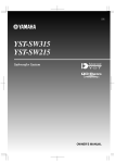
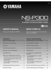
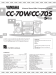
YST-SW200
Active Servo Processing Subwoofer System
Built-in 100W Power Amplifier
2 Way Selectability for Connections
High Frequency Cut-off Point (HIGH CUT) Control
PHASE Switch
Remote Control Capability
Thank you for selecting this YAMAHA Subwoofer System.
Active Servo
Technology
CAUTION
RISK OF ELECTRIC SHOCK
DO NOT OPEN
OWNER’S MANUAL
CAUTION: TO REDUCE THE RISK OF
ELECTRIC SHOCK, DO NOT REMOVE
COVER (OR BACK), NO USER-SERVICEABLE
PARTS INSIDE, REFER SERVICING TO
QUALIFIED SERVICE PERSONNEL.
CONTENTS
Safety Instructions.................... 2
Supplied Accessories............... 3
Features ................................... 4
Placement ................................ 4
Connections ............................. 5
Controls and Their Functions ... 8
Adjusting Volume Balance...... 10
Notes about the Remote
Control Transmitter ................. 12
Troubleshooting ...................... 12
Specifications ......................... 13
Active Servo Technology ........ 13
IMPORTANT!
Please record the serial number of this
unit in the space below.
• Explanation of Graphical Symbols
Model:
Serial No.:
The serial number is located on the rear
of the unit.
Retain this Owner’s Manual in a safe
place for future reference.
WARNING
TO REDUCE THE RISK OF FIRE OR
ELECTRIC SHOCK, DO NOT EXPOSE
THIS UNIT TO RAIN OR MOISTURE.
The lightning flash with arrowhead
symbol, within an equilateral triangle,
is intended to alert you to the
presence of uninsulated “dangerous
voltage” within the product’s
enclosure that may be of sufficient
magnitude to constitute a risk of
electric shock to persons.
The exclamation point within an
equilateral triangle is intended to alert
you to the presence of important
operating and maintenance
(servicing) instructions in the
literature accompanying the
appliance.
SAFETY INSTRUCTIONS
1
2
3
4
5
6
6A
7
8
9
10
Read Instructions – All the safety and operating
instructions should be read before the unit is operated.
Retain Instructions – The safety and operating instructions
should be retained for future reference.
Heed Warnings – All warnings on the unit and in the
operating instructions should be adhered to.
Follow Instructions – All operating and other instructions
should be followed.
Water and Moisture – The unit should not be used near
water – for example, near a bathtub, washbowl, kitchen
sink, laundry tub, in a wet basement, or near a swimming
pool, etc.
Carts and Stands – The unit should be used only with a
cart or stand that is recommended by the manufacturer.
A unit and cart combination should
be moved with care. Quick stops,
excessive force, and uneven
surfaces may cause the unit and
cart combination to overturn.
Wall or Ceiling Mounting – The unit
should be mounted to a wall or ceiling only as
recommended by the manufacturer.
Ventilation – The unit should be situated so that its
location or position does not interfere with its proper
ventilation. For example, the unit should not be situated
on a bed, sofa, rug, or similar surface, that may block the
ventilation openings; or placed in a built-in installation,
such as a bookcase or cabinet that may impede the flow
of air through the ventilation openings.
Heat – The unit should be situated away from heat
sources such as radiators, stoves, or other appliances that
produce heat.
Power Sources – The unit should be connected to a power
supply only of the type described in the operating
instructions or as marked on the unit.
11 Power-Cord Protection – Power-supply cords should be
12
13
14
15
A.
B.
C.
D.
E.
16
17
18
routed so that they are not likely to be walked on or
pinched by items placed upon or against them, paying
particular attention to cords at plugs, convenience
receptacles, and the point where they exit from the unit.
Cleaning – The unit should be cleaned only as
recommended by the manufacturer.
Nonuse Periods – The power cord of the unit should be
unplugged from the outlet when left unused for a long
period of time.
Object and Liquid Entry – Care should be taken so that
objects do not fall into and liquids are not spilled into the
inside of the unit.
Damage Requiring Service – The unit should be serviced
by qualified service personnel when:
The power-supply cord or the plug has been damaged;
or
Objects have fallen, or liquid has been spilled into the unit;
or
The unit has been exposed to rain; or
The unit does not appear to operate normally or exhibits a
marked change in performance; or
The unit has been dropped, or the cabinet damaged.
Servicing – The user should not attempt to service the unit
beyond those means described in the operating
instructions. All other servicing should be referred to
qualified service personnel.
Power Lines – An outdoor antenna should be located
away from power lines.
Grounding or Polarization – Precautions should be taken
so that the grounding or polarization is not defeated.
CAUTION: READ THIS BEFORE OPERATING YOUR UNIT
1 To assure the finest performance, please read this manual
2
3
4
5
6
7
2
carefully. Keep it in a safe place for future reference.
Install this unit in a cool, dry, clean place – away from
windows, heat sources, sources of excessive vibration,
dust, moisture and cold. Avoid sources of humming
(transformers, motors). To prevent fire or electrical shock,
do not expose the unit to rain or water.
Never open the cabinet. If something drops into the set,
contact your dealer.
Do not use force on switches, controls or connection
wires. When moving the unit, first disconnect the power
plug and the wires connected to other equipment. Never
pull the wire itself.
Do not attempt to clean the unit with chemical solvents;
this might damage the finish. Use a clean, dry cloth.
Be sure to read the “TROUBLESHOOTING” section
regarding common operating errors before concluding that
the unit is faulty.
When not planning to use this unit for long periods of time
(ie., vacation, etc.), disconnect the AC power plug from the
wall outlet.
8 To prevent lightning damage, disconnect the AC power
plug when there is an electrical storm.
9 Since this unit has a built-in power amplifier, heat will
10
11
12
radiate from the rear panel. Therefore, place the unit at
least 10 cm (4 inches) away from the wall. Also, do not
position with the rear panel facing down on the floor or
other surface.
Super-bass frequencies reproduced by this unit may
cause a turntable to generate a howling sound. In such a
case, move this unit away from the turntable.
This unit features a magnetically shielded design, but
there is still a chance that placing it too close to a TV set
might impair picture color. Should this happen, move this
unit away from the TV set.
If you hear distortion (i.e., unnatural, intermittent “rapping”
or “hammering” sounds) coming from this unit, reduce the
volume level. Extremely loud playing of a movie
soundtrack’s low frequency, bass-heavy sounds or
similarly loud popular music passages can damage this
speaker system.
FCC INFORMATION
1. IMPORTANT NOTICE : DO NOT MODIFY THIS UNIT!
This product, when installed as indicated in the
instructions contained in this manual, meets FCC
requirements. Modifications not expressly approved by
Yamaha may void your authority, granted by the FCC, to
use the product.
2. IMPORTANT : When connecting this product to
accessories and/or another product use only high quality
shielded cables. Cable/s supplied with this product
MUST be used. Follow all installation instructions.
Failure to follow instructions could void your FCC
authorization to use this product in the USA.
3. NOTE : This product has been tested and found to
comply with the requirements listed in FCC Regulations,
Part 15 for Class “B” digital devices. Compliance with
these requirements provides a reasonable level of
assurance that your use of this product in a residential
environment will not result in harmful interference with
other electronic devices.
This equipment generates/uses radio frequencies and, if
not installed and used according to the instructions
found in the users manual, may cause interference
harmful to the operation of other electronic devices.
Compliance with FCC regulations does not guarantee that
interference will not occur in all installations. If this product
is found to be the source of interference, which can be
determined by turning the unit “OFF” and “ON”, please try
to eliminate the problem by using one of the following
measures:
Relocate either this product or the device that is being
affected by the interference.
Utilize power outlets that are on different branch (circuit
breaker or fuse) circuits or install AC line filter/s.
In the case of radio or TV interference, relocate/reorient the
antenna. If the antenna lead-in is 300 ohm ribbon lead,
change the lead-in to coaxial type cable.
If these corrective measures do not produce satisfactory
results, please contact the local retailer authorized to
distribute this type of product. If you can not locate the
appropriate retailer, please contact Yamaha Electronics
Corp., U.S.A. 6660 Orangethorpe Ave, Buena Park, CA
90620.
The above statements apply ONLY to those products
distributed by Yamaha Corporation of America or its
subsidiaries.
We Want You Listening For A Lifetime
YAMAHA and the Electronic Industries Association’s
Consumer Electronics Group want you to get the most out of
your equipment by playing it at a safe level. One that lets the
sound come through loud and clear without annoying blaring or
distortion – and, most importantly, without affecting your
sensitive hearing. Since hearing damage from loud sounds is
often undetectable until it is too late, YAMAHA
and the Electronic Industries Association’s
Consumer Electronics Group recommend you to
avoid prolonged exposure from excessive
volume levels.
SUPPLIED ACCESSORIES
After unpacking, check that the following parts are contained.
Remote Control Transmitter
POWER
Batteries (size AA, R6, UM-3)
Speaker Cords
OUTPUT
ON/OFF
HIGH-CUT
VOLUME
UP
DOWN
3
FEATURES
•
This subwoofer system employs YAMAHA Active Servo
Technology which YAMAHA developed for reproducing
higher quality super-bass sound. (Refer to page 13 for
details on Active Servo Technology.)
This unit does not only enhance bass frequency response
of sound output in your audio system, but, by reproducing
the bass frequencies, the subwoofer permits your existing
amplifier and speakers to operate under less strenuous
conditions, improving overall system performance.
•
•
This unit can be added easily to your existing audio system
by connecting to either the speaker terminals or the line
output (pin jack) terminals of the amplifier.
For the effective use of this unit, this unit’s super-bass
sound must be matched to the sounds on your main
speakers. Therefore, this unit employs the continuously
variable high frequency cut-off point (HIGH-CUT) control.
Moreover, the PHASE switch allows you to select better
sound quality according to the listening condition.
PLACEMENT
A
B
If using one subwoofer system, it is recommended to place it
on the outside of either the right or the left main speaker. (See
fig. A .) If using two systems, it is recommended to place them
on the outside of each main speaker. (See fig. B .) The
placement shown in fig. C is also possible, however, if the
subwoofer system is placed directly facing the wall, the bass
effect may die because the sound from it and the sound
reflected by the wall will collide. To prevent this, face the
subwoofer system obliquely to the wall as shown in fig. A or
B.
4
C
One subwoofer system will have a good effect on your audio
system, however, the use of two subwoofer systems is
recommended to obtain more presence.
Note
There may be a case that you cannot obtain enough superbass sounds from this unit when listening at the middle of the
room. This is because the “standing waves” occur between
two parallel walls and the bass sounds are canceled.
In such a case, face the unit obliquely to the wall. It also may
be necessary to break up the parallel surfaces by placing
bookshelves etc. along the walls.
CONNECTIONS
• Before attempting to make any connections to or from this unit, be sure to first switch OFF the power to this unit and to any other
components to which connections are being made.
• When making connections between this unit and other components, be sure all connections are made correctly and consistently,
that is to say L (left) to L, R (right) to R, “+” to “+” and “–” to “–”.
• This unit can be connected to either the speaker terminals or the line output (pin jack) terminals of the amplifier. Choose one of
the ways shown below according to your audio system. Also, refer to the owner’s manual for each component to be connected
to this unit.
CONNECTING TO SPEAKER TERMINALS OF THE AMPLIFIER
• Disconnect your main speakers from the amplifier and connect them to this unit.
• To connect this unit to the amplifier, use the provided speaker cords.
If using one YST-SW200
Right speaker
Left speaker
OUTPUT
INPUT2
PHASE
TO SPEAKERS
This unit
OUTPUT
INPUT2
NOM REV
FROM AMPLIFIER
INPUT1
PHASE
TO SPEAKERS
NOM REV
FROM AMPLIFIER
INPUT1
Amplifier
To AC outlet
If using two YST-SW200s
Right speaker
Left speaker
OUTPUT
INPUT2
PHASE
This unit
OUTPUT
INPUT2
PHASE
INPUT2
PHASE
NOM REV
NOM REV
FROM AMPLIFIER
INPUT1
TO SPEAKERS
OUTPUT
TO SPEAKERS
TO SPEAKERS
FROM AMPLIFIER
INPUT1
This unit
OUTPUT
INPUT2
PHASE
TO SPEAKERS
NOM REV
NOM REV
FROM AMPLIFIER
INPUT1
FROM AMPLIFIER
INPUT1
Amplifier
To AC outlet
To AC outlet
5
If your amplifier has two sets of speaker terminals
Right speaker
This unit
OUTPUT
INPUT2
Left speaker
PHASE
TO SPEAKERS
OUTPUT
INPUT2
PHASE
TO SPEAKERS
NOM REV
FROM AMPLIFIER
INPUT1
NOM REV
FROM AMPLIFIER
INPUT1
To AC outlet
Amplifier
A
B
(Both “ A”and “ B” outputs
must be ON.)
Connecting to this unit’s OUTPUT/INPUT terminals
For connections, use speaker wires of the proper gauge, cut
as short as possible. If the connections are faulty, no sound
will be heard from the speakers. Make sure that the polarity of
the speaker wires is correct, that is, + and – markings are
observed. If these wires are reversed, the sound will be
unnatural and will lack bass. Do not let the bare speaker
wires touch each other and do not let them touch the
metal parts of this unit as this could damage this unit,
your amplifier and/or speakers.
How to Connect:
Red: positive (+)
Black: negative (–)
2
1
3
6
➀ Unscrew the knob.
➁ Insert the bare wire.
[Remove approx. 5mm
(1/4”) insulation from
the speaker wires.]
➂ Tighten the knob and
secure the wire.
* Banana Plug connections are also possible (except for
Europe model). Simply insert the Banana Plug connector
into the corresponding terminal.
CONNECTING TO LINE OUTPUT (PIN JACK) TERMINALS OF THE AMPLIFIER
• Leave the main speakers connected to the amplifier.
• Line output terminals may be labeled PRE OUT, REC OUT or SUBWOOFER OUT.
* For PRE OUT terminal connection, the amplifier must possess at least two sets of PRE OUT terminals. With some amplifiers
with only one set of PRE OUT terminals, connection can result in no sound from the main left and right speakers. In this
case, select an alternative method of connection.
If using one YST-SW200
Right speaker
This unit
OUTPUT
INPUT2
Left speaker
PHASE
TO SPEAKERS
OUTPUT
INPUT2
PHASE
TO SPEAKERS
NOM REV
FROM AMPLIFIER
INPUT1
NOM REV
FROM AMPLIFIER
INPUT1
Pin plug cords
To AC outlet
Amplifier
PRE OUT
If using two YST-SW200s
Right speaker
Left speaker
OUTPUT
INPUT2
PHASE
TO SPEAKERS
OUTPUT
INPUT2
NOM REV
FROM AMPLIFIER
INPUT1
This unit
OUTPUT
INPUT2
PHASE
NOM REV
Pin plug
cords
FROM AMPLIFIER
INPUT1
This unit
OUTPUT
TO SPEAKERS
PHASE
TO SPEAKERS
INPUT2
PHASE
TO SPEAKERS
NOM REV
NOM REV
FROM AMPLIFIER
INPUT1
FROM AMPLIFIER
INPUT1
PRE OUT
Amplifier
To AC outlet
To AC outlet
Notes
• When connected to the REC OUT terminals, if the amplifier has a REC OUT selector, be sure to set it for the correct source. For
information on its operation, consult the amplifier’s owner’s manual.
• When connected to line output terminals of the amplifier, other speakers should not be connected to the OUTPUT terminals on
the rear panel of this unit. If connected, they will not produce sound.
• When connecting to a monaural line output terminal of the amplifier, connect to either the left or right INPUT 2 terminal.
7
CONTROLS AND THEIR FUNCTIONS
Front panel
➊
➋
➌
OUTPUT
POWER
HIGH CUT
40 Hz
140 Hz
VOLUME
0
OUTPUT
10
POWER
HIGH CUT
40 Hz
➍
VOLUME
140 Hz
0
➎
10
➏
Rear panel
OUTPUT
INPUT2
PHASE
TO SPEAKERS
OUTPUT
NOM REV
INPUT2
PHASE
TO SPEAKERS
FROM AMPLIFIER
INPUT1
NOM REV
FROM AMPLIFIER
INPUT1
➐
Remote control transmitter
POWER
➍
OUTPUT
HIGH-CUT
➎
VOLUME
UP
DOWN
8
➑
ON/OFF
➏
➊
➏
POWER indicator
Illuminates when the POWER switch is turned ON, and
goes off when turned OFF.
* STANDBY mode (Australia, U.K. and Europe models)
While the power is on, pressing the POWER key on the
remote control transmitter switches the unit to the
STANDBY mode. (In this mode, the indicator is half
illuminated.)
POWER
POWER
/STANDBY
/STANDBY
POWER
POWER on mode
➋
POWER
VOLUME control
Adjusts the volume level.
For easier operation, use the VOLUME UP/DOWN keys
on the remote control transmitter.
➐
PHASE switch
Normally this switch is to be set to the normal (NOM)
position. However, according to your speaker systems or
the listening condition, there may be a case when better
sound quality is obtained by setting this switch to the
reverse (REV) position. Select the better position by
monitoring the sound.
➑
OUTPUT switch
Turns the output of this unit ON and OFF whenever
pressed. When this switch is turned ON, the OUTPUT
indicator on the front panel illuminates.
STANDBY mode
OUTPUT indicator
Illuminates when the OUTPUT switch is turned ON, and
goes off when turned OFF.
➌
Remote control sensor
Receives the signals from the remote control transmitter.
➍
POWER switch
Turns the power of this unit ON and OFF whenever
pressed. When this switch is turned ON, the indicator over
the POWER switch on the front panel illuminates.
➎
HIGH CUT control
Adjusts the high frequency cut off point.
Frequencies higher than the frequency selected by this
control are all cut off (and not output).
90
80
100
For easier operation, use the HIGH-CUT
70
110
UP/DOWN keys on the remote control
60
120
transmitter.
* One graduation of this control indicates 50
130
10 Hz.
40 Hz
140 Hz
9
ADJUSTING VOLUME BALANCE
For these operations, use the remote control transmitter at the listening position.
Front Panel
OUTPUT
POWER
2
OUTPUT
POWER
HIGH CUT
40 Hz
HIGH-CUT
5
VOLUME
ON/OFF
VOLUME
UP
4
2
140 Hz
5
0
10
1,4
DOWN
Rear Panel
OUTPUT
INPUT2
PHASE
TO SPEAKERS
NOM REV
FROM AMPLIFIER
INPUT1
6
1
2
3
4
5
6
10
Set the VOLUME control to minimum.
Turn on the power supply to all the components.
Play the source and adjust the amplifier’s volume control
to the desired listening level.
Turn up the VOLUME control gradually to adjust the
volume balance between this unit and the main speakers.
Adjust the HIGH CUT control to the position where the
desired response can be obtained.
Set the PHASE switch to the position (NOM or REV)
where the desired bass effect can be obtained.
Notes
• Once the volume balance between this unit and the main
speakers is adjusted, you can adjust the volume of your
whole sound system by using only the amplifier’s volume
control.
* However, if this unit is connected to line output terminals
(except PRE OUT or SUBWOOFER OUT terminals) of
the amplifier, you must adjust the volume controls of this
unit and the amplifier individually.
• For adjusting the VOLUME control, the HIGH CUT control
and the PHASE switch, refer to “FREQUENCY
CHARACTERISTICS” on the next page.
For effective adjustment of the HIGH CUT control
First set this control at about the main speakers’ rated
minimum reproduceable frequency. Then turn up the
VOLUME control gradually and set it at a level where you can
obtain a little more bass effect than when this unit is not used.
On the basis of this setting, if desired, adjust the VOLUME
control and the HIGH CUT control again.
* The main speakers’ minimum reproduceable frequency can
be looked up in the speakers’ catalog or owner’s manual.
FREQUENCY CHARACTERISTICS
Adjustment of the VOLUME control, the HIGH CUT control and the PHASE switch should be changed according to the main
speakers, listening condition, the source, etc.
The following figures show the optimum adjusting level of each control and the frequency characteristics on the condition that this
unit is combined with a typical speaker system.
This unit’s frequency characteristics
• When combined with a 4” or 5”
acoustic suspension, 2 way system
HIGH CUT
40 Hz
140 Hz
VOLUME
0
10
PHASE–Set to the reverse (REV) position.
• When combined with an 8” or 10”
acoustic suspension, 2 way system
HIGH CUT
40 Hz
140 Hz
VOLUME
0
10
PHASE–Set to the reverse (REV) position.
• When combined with a 12” acoustic
suspension, 3 way system
HIGH CUT
40 Hz
140 Hz
VOLUME
0
10
PHASE–Set to the reverse (REV) position.
11
NOTES ABOUT THE REMOTE CONTROL TRANSMITTER
Battery installation
Remote control transmitter operation range
1
3
Remote control
sensor
2
Within approximately
7 m (23 feet)
30°
Battery replacement
If you find that the remote control transmitter must be used
closer to the main unit, the batteries are weak. Replace both
batteries with new ones.
Notes
● Use only AA, R6, UM-3 batteries for replacement.
● Be sure the polarities are correct. (See the illustration inside
the battery compartment.)
● Remove the batteries if the remote control transmitter will
not be used for an extended period of time.
● If batteries leak, dispose of them immediately. Avoid
touching the leaked material or letting it come in contact with
clothing, etc. Clean the battery compartment thoroughly
before installing new batteries.
30°
Notes
● There should be no large obstacles between the remote
control transmitter and the main unit.
● If the remote control sensor is directly illuminated by strong
lighting (especially an inverter type of fluorescent lamp etc.),
it might cause the remote control transmitter not to work
correctly. In this case, reposition the main unit to avoid
direct lighting.
TROUBLESHOOTING
If the unit fails to operate normally, check the following points to determine whether the fault can be corrected by the simple
measures suggested. If it cannot be corrected, or if the fault is not listed in the SYMPTOM column, disconnect the power cord and
contact your authorized YAMAHA dealer or service center for help.
SYMPTOM
REMEDY
Power is not supplied even though the
POWER switch is ON.
The power plug is not securely connected.
Connect it securely.
No sound .
The VOLUME control is set to 0.
Turn the VOLUME control to right.
The OUTPUT switch is OFF.
Press the OUTPUT switch so that the
OUTPUT indicator on the front panel
illuminates.
Speaker cables are not connected securely.
Connect them securely.
Speaker cables are connected incorrectly.
Connect them correctly, that is to say L (left)
to L, R (right) to R, “+” to “+” and “–” to “–”.
Setting of the PHASE switch is not proper.
Set the switch to the other position.
A source sound with few bass frequencies is
played.
Play a source sound with bass frequencies.
Set the HIGH-CUT control to a higher
position. (Turn the knob to right.)
It is influenced by the standing waves.
Break up the parallel surface by placing
bookshelves etc. along the walls.
The remote control transmitter does not
work.
Direct sunlight or lighting (of an inverter type
of flourescent lamp etc.) is striking the
remote control sensor of the main unit.
Change position of the main unit.
The distance or range within which the
remote control transmitter can be used
decreases.
The batteries of this remote control
transmitter are too weak.
Replace the batteries with new ones.
Sound level is too low.
12
CAUSE
SPECIFICATIONS
Speaker Unit .................18 cm (7-1/16”) cone woofer (JA1815)
magnetic-shield type x 2
Amplifier Output ................100W/5 ohms (THD 0.1%, 100 Hz)
High-Cut Filter...............................40 Hz–140 Hz (–24 dB/oct.)
Frequency Response ..........................20 Hz–160 Hz (–10 dB)
Power Supply
U.S.A. and Canada models........................AC 120V, 60 Hz
Australia and U.K. models.........................AC 240V, 50 Hz
Europe model .............................................AC 230V, 50 Hz
General model ..................AC 110/120/220/240V, 50/60 Hz
Power Consumption........................................................130W
Dimensions (W x H x D) .............240 mm x 590 mm x 400 mm
(9-7/16” x 23-1/4” x 15-3/4”)
Weight ......................................................18 kg (39 lbs. 10 oz.)
Accessories ....................................Remote control transmitter
Batteries
Speaker cords
ACTIVE SERVO TECHNOLOGY
The theory of Active Servo Technology is based upon two
major factors, the Helmholtz resonator and negativeimpedance drive. Active Servo Processing speakers
reproduce the bass frequencies through an “air woofer”,
which is a port or opening in the speaker’s cabinet. This
opening is used instead of, and performs the functions of, a
woofer in a conventionally designed speaker system.
Thus, signals of low amplitude within the cabinet can,
according to the Helmholtz resonance theory, be output
from this opening as waves of great amplitude if the design
is such that the size of the opening and the volume of the
cabinet are in the correct proportion to satisfy a certain
ratio.
In order to accomplish this, moreover, the amplitudes within
the cabinet must be both precise and of sufficient power
because these amplitudes must overcome the “load”
presented by the air that exists within the cabinet.
Highamplitude
bass
sound
Cabinet
Thus it is this problem that is resolved through the
employment of a design in which the amplifier functions to
supply special signals. If the electrical resistance of the voice
coil could be reduced to zero, the movement of the speaker
unit would become linear with respect to signal voltage, and,
to accomplish this, a special negative-impedance output-drive
amplifier for subtracting output impedance of the amplifier is
used.
By employing negative-impedance drive circuits, the amplifier
is able to generate precise, low-amplitude low-frequency
waves with superior damping characteristics, and these waves
are then radiated from the cabinet opening as high-amplitude
signals. The system can, therefore, by employing the
negative-impedance output drive amplifier and a speaker
cabinet with the Helmholtz resonator, reproduce an extremely
wide range of frequencies with amazing sound quality and
less distortion.
The features described above, then, are combined to be the
fundamental structure of the Active Servo Technology.
Air woofer
(Helmholtz resonator)
Port
Active Servo
Processing
Amplifier
Signals of low amplitude
Signals
Negative-impedance
output drive
13
YAMAHA
YAMAHA
YAMAHA
YAMAHA
YAMAHA
YAMAHA
YAMAHA
ELECTRONICS CORPORATION, USA 6660 ORANGETHORPE AVE., BUENA PARK, CALIF. 90620, U.S.A.
CANADA MUSIC LTD. 135 MILNER AVE., SCARBOROUGH, ONTARIO M1S 3R1, CANADA
ELECTRONIK EUROPA G.m.b.H. SIEMENSSTR. 22-34, D-25462 RELLINGEN BEI HAMBURG, F.R. OF GERMANY
ELECTRONIQUE FRANCE S.A. RUE AMBROISE CROIZAT BP70 CROISSY-BEAUBOURG 77312 MARNE-LA-VALLEE CEDEX02, FRANCE
ELECTRONICS (UK) LTD. YAMAHA HOUSE, 200 RICKMANSWORTH ROAD WATFORD, HERTS WD1 7JS, ENGLAND
SCANDINAVIA A.B. J A WETTERGRENS GATA 1, BOX 30053, 400 43 VÄSTRA FRÖLUNDA, SWEDEN
MUSIC AUSTRALIA PTY, LTD. 17-33 MARKET ST., SOUTH MELBOURNE, 3205 VIC., AUSTRALIA