1
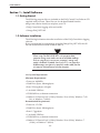
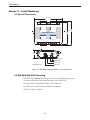
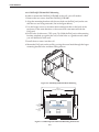
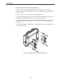
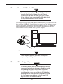
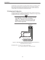
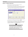
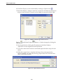
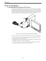
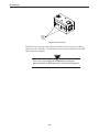
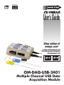
MADE IN
®
User’s Guide
Shop online at
omega.com ®
e-mail: [email protected]
For latest product manuals:
omegamanual.info
OM-DAQ-USB-2401
Multiple Channel USB Data
Acquisition Module
Install Software
Section 1 – Install Software
1.1 Getting Started
The following program files are included on the DAQ Central User Software CD
supplied with your unit. These files can also be downloaded from the
omega.com website should you misplace your CD.
• DAQ Central data logging software installer
• Omega.DAQ .NET API
1.2 Software Installation
The following instructions describe installation of the DAQ Central data logging
software.
If you are interested in programming using the Omega.Daq .NET API, the .dll
file and documentation can be found on the CD.
NOTE:
When using OM-DAQ-USB-2401 unit to acquire data,
computer energy save modes can cause false data readings.
Prior to using the unit, ensure your computer's energy save
mode is disabled. If needed, consult your PC’s user manual to
disable energy save (power suspension) modes.cable) that the
unit requires minimal power from the computer.
1.2.1 System Requirements
Minimum Requirements:
• Processor: 800 MHz
• Hard Drive Space: 300 megabytes
• Ram: 512 megabytes or higher
• 1 Available USB Port
• CD-ROM Drive or Internet connection
• Windows XP Service Pack 3 (32-bit), Windows Vista (32-bit), Windows 7 (32bit), or Windows 7 (64-bit)
Recommended Requirements:
• Processor: 1.5 GHz
• Hard Drive Space: 300 megabytes
• Ram: 1.5 gigabytes
• 1 Available USB Port
• CD-ROM Drive or Internet connection
• Windows XP Service Pack 3 (32-bit), Windows Vista (32-bit), Windows 7
(32-bit), or Windows 7 (64-bit)
1-1
Install Software
1.2.2 Software Setup
Insert the DAQ Central Software CD that was included with your DAQ unit into
the CD-ROM drive on your PC. Your system should begin the installation
process automatically. If the software installation does not start automatically:
open: "My Computer", double-click your CD-ROM drive, and run :setup.exe".
Figure 1-1. Welcome Screen
This welcome screen should be visible on your computer screen. To continue
with installing the program click the “Next >” button.
From this screen you select the folder were you want the program files installed
on your PC. The default setting will install the software under your “Program”
folders in a new folder named “Omega” To continue with installing the program
click the “Next >” button.
Figure 1-2. Select Install Screen
1-2
Install Software
Figure 1-3. Confirm Installation Screen
The setup wizard now has all the information to complete the installation of the
software on your PC. To continue with installing the program click the “Next >”
button.
During the install process, a Windows Command Prompt may pop up. No
interaction is required in this window; it is automatically installing or updating
the device’s USB drivers. Please let this process complete before closing the
software installation wizard.
Congratulations! You have just successfully installed the DAQ Central Program
on your PC. To end installing the program and close the setup wizard click the
“Close” Button.
1-3
Install Hardware
Section 2 - Install Hardware
2.1 Overall Dimensions
127 (5.00)
A A C A A C E C
5 5 O 6 6 O X O
H L M H L M C M
ANALOG INPUT
12 V OUT
CHANNEL 5 & 6
A A C A A C E C
7 7 O 8 8 O X O
H L M H L M C M
!
ANALOG INPUT
12 V OUT
CHANNEL 7 & 8
OM-DAQ-USB-2400 SERIES
USB DATA ACQUISITION SYSTEM
CHANNEL 1 & 2
ANALOG INPUT
12 V OUT
!
A A C A A C E C
1 1 O 2 2 O X O
H L M H L M C M
107
(4.20)
97
(3.80)
CHANNEL 3 & 4
ANALOG INPUT
12 V OUT
A A C A A C E C
3 3 O 4 4 O X O
H L M H L M C M
-
38
(1.5)
+
EXT
PWR
USB
STATUS
PWR
IND
9V
1.0 A
POWER SUPPLY
POWER LED
STATUS LED
DIMENSIONS mm (in)
USB PORT
Figure 2-1. OM-DAQ-USB-2401 Hardware and Dimensions
2.2 OM-DAQ-USB-2401 Mounting
The OM-DAQ-USB-2401 mounting kit contains the following accessories:
• 2 mounting brackets (to be used for either wall or DIN rail)
• 4 long screws (to be used for either wall or DIN rail)
• 4 short screws (to be used for the DIN rail adaptor)
• 2 DIN rail plastic adaptors
2-1
Install Hardware
2.2.1 OM-DAQ-USB-2401 Wall Mounting
In order to mount the OM-DAQ-USB-2401 to the wall, you will need to:
1. Remove the rear screws from the OM-DAQ-USB-2401.
2. Align the mounting brackets with the rear holes on the DAQ unit (make sure
that the ears are facing outwards, like in the figure below).
3. Use the longer screws to reconnect the mounting brackets to the body of the
enclosure, in the same direction as the screws that were removed from the
DAQ unit.
4. Drill 2 holes for #4 screws, 5.50" apart. Tip: Hold the DAQ unit with mounting
brackets attached, up against the wall; use the holes as a guide to mark where
you will drill holes in the wall.
5. Install the two screws into the wall.
6. Mount the DAQ unit on the wall by passing the screw head through the larger
mounting bracket holes and then sliding it down.
Figure 2-2. OM-DAQ-USB-2401 Wall Mounting
146 (6.00)
133 (5.50)
MOUNTING HOLE DISTANCE
ANALOG INPUT
12 V OUT
CHANNEL 5 & 6
A A C A A C E C
7 7 O 8 8 O X O
H L M H L M C M
!
ANALOG INPUT
12 V OUT
CHANNEL 7 & 8
Ø6
2 PLACES
(0.25)
A A C A A C E C
5 5 O 6 6 O X O
H L M H L M C M
Ø3
2 PLACES
(0.125)
OM-DAQ-USB-2400 SERIES
107
(4.20)
USB DATA ACQUISITION SYSTEM
CHANNEL 1 & 2
ANALOG INPUT
12 V OUT
A A C A A C E C
1 1 O 2 2 O X O
H L M H L M C M
!
CHANNEL 3 & 4
ANALOG INPUT
12 V OUT
A A C A A C E C
3 3 O 4 4 O X O
H L M H L M C M
Figure 2-3. OM-DAQ-USB-2401 Wall Mounting Dimensions
2-2
Install Hardware
2.2.2 OM-DAQ-USB-2401 DIN Rail Mounting
In order to mount the OM-DAQ-USB-2401 to a DIN-Rail, you will need to:
1. Attach the DIN-rail plastic adaptors to the mounting brackets, using the four
shorter screws.
2. Remove the rear screws from the OM-DAQ-USB-2401.
3. Align the mounting brackets with the rear holes on the DAQ unit (make sure
that the ears are facing inwards, as shown in the figure below).
4. Use the longer screws to reconnect the mounting brackets to the body of the
enclosure, in the same direction as the screws that were removed from the
DAQ unit.
5. Attach the DAQ unit to the DIN rail, using the plastic adaptors attached to the
mounting brackets.
Figure 2-4. OM-DAQ-USB-2401 DIN-Rail Mounting
2-3
Install Hardware
2.2 Connect Personal DAQ to Host PC
NOTE:
When using a power adapter with your DAQ system, be sure
to supply power (from the adapter to the DAQ) before
connecting the USB cable. This allows your DAQ to inform
the host computer (upon connection of the USB cable) that the
unit requires minimal power from the computer.
Use an approved high-speed USB cable to connect the DAQ system to one of the
host computer’s USB ports. Usually, there is no need to use an additional power
supply in this setup, since most of computer USB ports supply 5 V, 500mA of
power. Additional setup examples are described in the full manual (M5025),
some of which involve USB hubs and/or power adapters.
POWER
ADAPTER
(OPTIONAL)
USB
Figure 2-5. Connection of an OM-DAQ USB-2401 Unit to a Computer USB Port
NOTE:
Certain notebook computers require the use of a power
adapter with your Omega DAQ unit.
2.3 Connect Channel Signal Inputs
CAUTION:
The discharge of static electricity can damage some electronic
components. Semiconductor devices are especially susceptible
to ESD damage. You should always handle components
carefully, and you should never touch connector pins or
circuit components unless you are following ESD guidelines in
an appropriate ESD controlled area. Such guidelines include
the use of properly grounded mats and wrist straps, ESD
bags and cartons, and related procedures.
2-4
Install Hardware
Use the DAQ’s screw terminals to connect channel inputs to your DAQ system.
Note that the terminal blocks are detachable for ease in making connections.
Each Analog Input channel can be configured for single-ended or differential
voltage inputs, or for differential thermocouple inputs.
2.4 Analog Input Configuration
The OM-DAQ-USB-2401 include 16 analog signal inputs which may be used as
16 single-ended inputs, 8 differential inputs, or as a combination of single-ended
and differential inputs with up to 16 connections.
NOTE:
In DAQ applications, thermocouples should not be connected
single-ended. Doing so can result in noise and false
readings. This is especially true when acquiring other highamplitude signals in conjunction with thermocouple signals
that are connected single-ended.
OM-DAQ-USB-2401
TERMINAL BLOCK
(PARTIAL)
A
1
H
A
1
L
C
O
M
A
2
H
A
2
L
V1
V2
COM
V3+
V3
V3–
Figure 2-6. OM-DAQ-USB-2401 Single-Ended and Differential Connections to
Analog Input Channels Diagram’
FIGURE NOTES: *V1 and V2 are single-ended inputs
*V3 is a thermocouple and is a differential input.
2-5
Software Quick Start
Section 3 - Software Quick Start
1. Install the software, using the Software Installation instructions.
2. Connect the device to the PC using the USB cable.
3. Run the DAQ software. After loading, the software will detect all supported
devices that are connected. If a device is connected after loading the software,
a search can be initiated by clicking “Detect Devices” in the Device menu.
4. Select your device, which is identified by its USB serial number.
Figure 3-1. Select Device Screen
5. Configure the device by clicking the Device Settings icon
.
6. The desired channels can be enabled and configured using the Channels tab of
the Device Configuration screen. Readings are in units of Volts for voltage
input ranges, and degrees F or C for thermocouple input ranges. Note that
thermocouples need to be connected in Differential mode.
NOTE:
When using OM-DAQ-USB-2401 unit to acquire data,
computer energy save modes can cause false data readings.
Prior to using the unit, ensure your computer's energy save
mode is disabled. If needed, consult your PC’s user manual to
disable energy save (power suspension) modes.
3-1
Software Quick Start
Figure 3-2. Configuration Mode - Channels Tab Screen
7. Set the desired scan rate. The maximum possible scan rate will be adjusted
and displayed as channels are enabled and disabled. Using thermocouple
inputs will also lower the maximum possible scan rate.
3-2
Software Quick Start
8. To save data to a file on the PC, select the Data tab and choose a filename.
This data can be saved in binary or .CSV format. Binary format is smaller and
faster, and recommended for slower machines. It can be converted to .CSV
format later.
Figure 3-3. Configuration Mode - Data Tab Screen
9. From the Main Window, you can choose to view live data from any
combination of Tables, Bars, Gauges, Digital Displays, and Waveforms. These
displays can be opened by clicking the appropriate button:
Figure 3-4. Main Window Screen
Figure 3-5. Gauges Screen
3-3
Software Quick Start
10. Each Data Display can be customized by clicking its Options icon
.
11. Each Data Display’s Options screen lets you choose which device channels to
display in that window. Channels can be added or removed with the Add
Figure 3-6. Adding or Removing Channels Screen
Display
and Delete Display
OK button.
buttons. Confirm changes by clicking the
12. Start Acquisition by clicking the Play button on the Main Window.
Acquisition can be stopped with the Stop button.
13. If you have more than one device connected, repeat the above steps for each
device.
14. When data acquisition is complete, the binary data can be exported to
human-readable .csv format by choosing “Export Data File” from the Tools
menu in the Main Window.
Figure 3-7. Export Data File Screen
3-4
CE Conformity
Section 4 - CE Conformity
4.1 OM-DAQ-USB-2401 Design for CE Conformity
The OM-DAQ-USB-2401 has been designed to meet requirements as outlined in
European Community EMC Directive EN61326. Three ferrite cores are included
in the OM-DAQ-USB-2401 package. When powering the unit using the adapter,
the ferrite cores must be attached to both the USB cable and the power adapter to
meet EFT (Electrical Fast Transient) specifications. Refer to Figure 4-1
POWER
ADAPTER
US
B
(MIDPOINT OF CABLES)
Figures 4 -1. OM-DAQ-USB-2401 with Ferrite Cores Installed
To maintain CE certification and install the ferrite cores, perform the following:
1. Using a small screw driver or other suitable instrument, unsnap the ferrite
core to open it (as shown in Figure 4-2.
2. Install one ferrite core on each far end of the USB cable, and one ferrite core in
the middle of the cable (as shown in Figure 4-1).
3. Install one ferrite core on each far end of the power adapter, and one ferrite
core in the middle of the cable (as shown in Figure 4-1).
4-1
CE Conformity
UNSNAP
FERRITE
CORES
HERE
Figure 4-2 Ferrite Core
The ferrite cores may be removed from the DAQ unit; however, in order to
conform to CE standards, all of the ferrite cores must be attached to the USB
cable and power adapter.
NOTE:
If the user is not using the power adapter but relying on
power from the host USB connection, no ferrites are required.
4-2
Specifications
Section 5 - Specifications
General
Isolation:
500V from PC
External Excitation Output Voltage:
+12 vDC Regulated, Maximum total
current output 67mA
Power Requirements:
Powered direct from USB port, max 500
mA, or fromexternal 7.5 to 12 Vdc
Environmental:
0 to 50°C (0 to 122°F) 95% RH
(non-condensing)
Operating Temperature:
0 to 50°C (32 to 122°F), 0 to 95% RH noncondensing
Storage Temperature:
-40 to 85°C (-40 to 185°F)
Weight:
0.5 lbs (0.23 kg)
Dimensions:
107 W x 128 L x 39mm H (4.2 x 5.1 x 1.5")
Input Voltage Range:
Software-programmable On A Perchannel Basis
Differential/Single-ended:
-10 to 10V
-5 to 5V
-2.5 to 2.5V
-2 to 2V
-1 to 1V
-500 to 500 mV
-250 to 250 mV
-125 to 125 mV
-75 to 75 mV
-30 to 30 mV
TC Input Range:
Type J: -18 to 1200°C (0 to 2192°F)
Type K: -129 to 1372°C (-200 to 2502°F)
Type T: -101 to 400°C (-150 to 752°F)
Type E: -184 to 1000°C (-300 to 1832°F)
Type R: 204 to 1768°C (400 to 3214°F)
Type S: 204 to 1768°C (400 to 3214°F)
Type B: 538 to 1820°C (1000 to 3308°F)
Type N: -129 to 1300°C (-200 to 2372°F)
TC Input Thermocouple Accuracy:
In very slow mode, 24 bit resolution
J = ±1.1°C
K = ±1.2°C
T = ±1.1°C
E = ±1.0°C
R = ±2.5°C
S = ±2.6°C
B = ±3.3°C
N = ±1.5°C
Cold Junction
Compensation Accuracy:
±1.0°C
5-1
Specifications
Analog Input Accuracy: (exclusive of noise)
Differential Input:
In very slow mode, 0.015% of reading +
.004% of range + 10uV(exclusive of noise)
Single-end Input:
In very slow mode, 0.05% of reading +
0.01% of range + 50uV(exclusive of noise)
USB Device Type:
USB 2.0 (full-speed)
Device Compatibility:
USB 1.1, USB 2.0
Power Supply:
From USB (Port) or 9 Vdc adaptor
DIN Rail Mounted
For Rack Application:
Optional
Automatically enabled when a channel is
configured for a thermocouple sensor.
Open Thermocouple Detect:
Limitations of the Total
Recording Memory Size:
1 G or 500M (in PC)
MCU:
32 bit
OMB-DAQ-USB-2401 Series Block Diagram
Power LED
Isolation
Barrier
Power Supply
Isolated
Power Supply
Power Jack
Local Power
USB
Jack
USB
Controller
MCU
32Bit
Activity LED
Digital Isolators
CJC
4
Analog Inputs
Gain =
x2, 1/8
+12v
+12v output
Excitation voltage
SE/
DI
MUX
CJC
PGIA
4
Analog Inputs
Gain =
x1,2,4,8,16
32,64
+12v output
Excitation voltage
1MΩ
MUX
1MΩ
PGA
CJC
4
Analog Inputs
Gain =
x2, 1/8
+12v
+12v output
Excitation voltage
CJC
SE/
DI
MUX
PGIA
4
Analog Inputs
+12v output
Excitation voltage
1MΩ
1MΩ
Figure 5-1. OM-DAQ-USB 2401 Series Block Diagram
5-2
24–Bit
A/D
Approvals and Regulatory Compliance
6.1 International Usage & CE Marking
The OM-DAQ-USB-2401 multiple channel USB data acquisition module is CE
marked and certified for use in several European countries. Please contact
OMEGA for information on International Regulatory Compliance for each
country.
It is your (the user’s) responsibility to insure that these products are operated
within the guidelines here in this manual and in conformance with all local or
national regulations and laws.
6-1
®
OMEGAnet ® Online Service
omega.com
Internet e-mail
[email protected]
Servicing Europe:
Servicing North America:
U.S.A.:
ISO 9001 Certified
Canada:
Omega Engineering, Inc., One Omega Drive, P.O. Box 4047
Stamford, CT 06907-0047
Toll-Free: 1-800-826-6342
Tel: (203) 359-1660
FAX: (203) 359-7700
e-mail: [email protected]
976 Bergar
Laval (Quebec), H7L 5A1 Canada
Toll-Free: 1-800-826-6342
TEL: (514) 856-6928
FAX: (514) 856-6886
e-mail: [email protected]
Benelux:
Managed by the United Kingdom Office
Toll-Free: 0800 099 3344
TEL: +31 20 347 21 21
FAX: +31 20 643 46 43
e-mail: [email protected]
Czech Republic:
Frystatska 184
733 01 Karviná, Czech Republic
Toll-Free: 0800-1-66342
TEL: +420-59-6311899
FAX: +420-59-6311114
e-mail: [email protected]
France:
Managed by the United Kingdom Office
Toll-Free: 0800 466 342
TEL: +33 (0) 161 37 29 00
FAX: +33 (0) 130 57 54 27
e-mail: [email protected]
For immediate technical or application assistance:
U.S.A. and Canada: Sales Service: 1-800-826-6342/1-800-TC-OMEGA®
Germany/Austria: Daimlerstrasse 26, D-75392 Deckenpfronn, Germany
Toll-Free: 0800 6397678
FAX: +49 (0) 7056 9398-29
Customer Service: 1-800-622-2378/1-800-622-BEST®
Engineering Service: 1-800-872-9436/1-800-USA-WHEN®
Mexico/
Latin America
En Español: 001 (203) 359-7803
[email protected]
FAX: 000 (203) 359-7807
e-mail:[email protected]
TEL: +49 (0) 7056 9398-0
e-mail: [email protected]
United Kingdom: OMEGA Engineering Ltd.
ISO 9001 Certified
One Omega Drive, River Bend Technology Centre, Northbank
Irlam, Manchester M44 5BD United Kingdom
Toll-Free: 0800-488-488
TEL: +44 (0) 161 777-6611
FAX: +44 (0) 161 777-6622
e-mail: [email protected]
It is the policy of OMEGA Engineering, Inc. to comply with all worldwide safety and EMC/EMI regulations that apply. OMEGA is constantly pursuing certification of its products to the European New Approach Directives. OMEGA will add the CE mark to every appropriate device upon certification.
The information contained in this document is believed to be correct, but OMEGA accepts no liability for any errors it contains, and reserves the right to alter specifications without notice. WARNING: These products are not designed for use in, and should not be used for, human applications.
WARRANTY/DISCLAIMER
OMEGA ENGINEERING, INC. warrants this unit to be free of defects in materials and workmanship for a period of 13 months from date of purchase.
OMEGA’s WARRANTY adds an additional one (1) month grace period to the normal one (1) year product warranty to cover handling and
shipping time. This ensures that OMEGA’s customers receive maximum coverage on each product.
If the unit malfunctions, it must be returned to the factory for evaluation. OMEGA’s Customer Service Department will issue an Authorized Return (AR)
number immediately upon phone or written request. Upon examination by OMEGA, if the unit is found to be defective, it will be repaired or replaced
at no charge. OMEGA’s WARRANTY does not apply to defects resulting from any action of the purchaser, including but not limited to mishandling,
improper interfacing, operation outside of design limits, improper repair, or unauthorized modification. This WARRANTY is VOID if the unit shows evidence of having been tampered with or shows evidence of having been damaged as a result of excessive corrosion; or current, heat, moisture or vibration; improper specification; misapplication; misuse or other operating conditions outside of OMEGA’s control. Components in which wear is not
warranted, include but are not limited to contact points, fuses, and triacs.
OMEGA is pleased to offer suggestions on the use of its various products. However, OMEGA neither assumes responsibility for any omissions or errors nor assumes liability for any damages that result from the use of its products in accordance with information provided by
OMEGA, either verbal or written. OMEGA warrants only that the parts manufactured by the company will be as specified and free of
defects. OMEGA MAKES NO OTHER WARRANTIES OR REPRESENTATIONS OF ANY KIND WHATSOEVER, EXPRESSED OR IMPLIED,
EXCEPT THAT OF TITLE, AND ALL IMPLIED WARRANTIES INCLUDING ANY WARRANTY OF MERCHANTABILITY AND FITNESS FOR A PARTICULAR PURPOSE ARE HEREBY DISCLAIMED. LIMITATION OF LIABILITY: The remedies of purchaser set forth herein are exclusive, and the
total liability of OMEGA with respect to this order, whether based on contract, warranty, negligence, indemnification, strict liability or otherwise, shall not exceed the purchase price of the component upon which liability is based. In no event shall OMEGA be liable for consequential, incidental or special damages.
CONDITIONS: Equipment sold by OMEGA is not intended to be used, nor shall it be used: (1) as a “Basic Component” under 10 CFR 21 (NRC), used in
or with any nuclear installation or activity; or (2) in medical applications or used on humans. Should any Product(s) be used in or with any nuclear
installation or activity, medical application, used on humans, or misused in any way, OMEGA assumes no responsibility as set forth in our basic WARRANTY/ DISCLAIMER language, and, additionally, purchaser will indemnify OMEGA and hold OMEGA harmless from any liability or damage whatsoever arising out of the use of the Product(s) in such a manner.
RETURN REQUESTS / INQUIRIES
Direct all warranty and repair requests/inquiries to the OMEGA Customer Service Department. BEFORE RETURNING ANY PRODUCT(S) TO
OMEGA, PURCHASER MUST OBTAIN AN AUTHORIZED RETURN (AR) NUMBER FROM OMEGA’S CUSTOMER SERVICE DEPARTMENT (IN ORDER
TO AVOID PROCESSING DELAYS). The assigned AR number should then be marked on the outside of the return package and on any
correspondence.
The purchaser is responsible for shipping charges, freight, insurance and proper packaging to prevent breakage in transit.
FOR WARRANTY RETURNS, please have the following information
available BEFORE contacting OMEGA:
1. Purchase Order number under which the product was PURCHASED,
2. Model and serial number of the product under warranty, and
3. Repair instructions and/or specific problems relative to the product.
FOR NON-WARRANTY REPAIRS, consult OMEGA for current repair charges.
Have the following information available BEFORE contacting OMEGA:
1. Purchase Order number to cover the COST of the repair,
2. Model and serial number of the product, and
3. Repair instructions and/or specific problems relative to the product.
OMEGA’s policy is to make running changes, not model changes, whenever an improvement is possible. This affords our customers the latest in technology and engineering. OMEGA is a registered trademark of OMEGA ENGINEERING, INC.
© Copyright 2012 OMEGA ENGINEERING, INC. All rights reserved. This document may not be copied, photocopied, reproduced, translated, or reduced to any electronic
medium or machine-readable form, in whole or in part, without the prior written consent of OMEGA ENGINEERING, INC.
MQS5025/0112