1
Home
Contents
Page:
Preface and general safety instructions
Part 1: class 69 operating instructions
1.
Product description . . . . . . . . . . . . . . . . . . . . . . . . . . . .
5
2.
Designated use . . . . . . . . . . . . . . . . . . . . . . . . . . . . . .
5
3.
3.1
Subclasses
Optional extras . . . . . . . . . . . . . . . . . . . . . . . . . . . . . . .
6
4.
Technical data . . . . . . . . . . . . . . . . . . . . . . . . . . . . . . .
6
5.
5.1
5.2
5.2.1
5.2.2
5.3
5.4
5.5
5.6
5.7
5.8
5.9
5.10
5.11
5.12
5.13
5.14
5.15
Operation
Folding down left-hand half of table plate (MG
Threading the needle thread . . . . . . . . . .
Subclass 69-373 . . . . . . . . . . . . . . . .
Subclass 69-FA-373 . . . . . . . . . . . . . .
Adjusting the needle-thread tension . . . . .
Opening the needle-thread tensioner . . . . .
Winding on the looper thread . . . . . . . . .
Fitting the looper-thread bobbin . . . . . . . .
Adjusting the looper-thread tension . . . . . .
Fitting and changing the needle . . . . . . . .
Lifting the sewing feet . . . . . . . . . . . . .
Locking the sewing feet in the raised position
Adjusting the sewing-foot stroke . . . . . . .
Adjusting the sewing-foot pressure . . . . . .
Adjusting the stitch length . . . . . . . . . . .
Welting . . . . . . . . . . . . . . . . . . . . .
Ribbon binder (class 69-373) . . . . . . . . .
56-2
. . .
. . .
. . .
. . .
. . .
. . .
. . .
. . .
. . .
. . .
. . .
. . .
. . .
. . .
. . .
. . .
frame only)
. . . . . . .
. . . . . . .
. . . . . . .
. . . . . . .
. . . . . . .
. . . . . . .
. . . . . . .
. . . . . . .
. . . . . . .
. . . . . . .
. . . . . . .
. . . . . . .
. . . . . . .
. . . . . . .
. . . . . . .
. . . . . . .
.
.
.
.
.
.
.
.
.
.
.
.
.
.
.
.
.
.
.
.
.
.
.
.
.
.
.
.
.
.
.
.
.
.
.
.
.
.
.
.
.
.
.
.
.
.
.
.
.
.
.
.
.
.
.
.
.
.
.
.
.
.
.
.
.
. 20
.
.
9
10
10
11
13
13
15
15
17
17
19
19
19
20
6.
6.1
6.2
6.2.1
6.2.2
6.3
6.3.1
6.3.2
Control unit and operating panel
General . . . . . . . . . . . . . . . .
Efka VD554KV/6F82AV sewing drive
Control-box buttons . . . . . . . . .
Altering parameter values . . . . . .
Quick QD554/A51K01 sewing drive .
Operating-panel buttons . . . . . . .
Altering parameter values . . . . . .
.
.
.
.
.
.
.
.
.
.
.
.
.
.
.
.
.
.
.
.
.
.
.
.
.
.
.
.
.
.
.
.
.
.
.
.
.
.
.
.
.
.
23
24
24
26
28
28
30
.
.
.
.
.
.
.
.
.
.
.
.
.
.
.
.
.
.
.
.
.
.
.
.
.
.
.
.
.
.
.
.
.
.
.
.
.
.
.
.
.
.
.
.
.
.
.
.
.
.
.
.
.
.
.
.
.
.
.
.
.
.
.
.
.
.
.
.
.
.
.
.
.
.
.
.
.
.
.
.
.
.
.
.
.
.
.
.
.
.
.
21
22
Contents
Page:
7.
Sewing . . . . . . . . . . . . . . . . . . . . . . . . . . . . . . . . . . .
32
8.
8.1
8.2
Maintenance . . . . . . . . . . . . . . . . . . . . . . . . . . . . . . .
Cleaning and testing . . . . . . . . . . . . . . . . . . . . . . . . . . .
Lubrication . . . . . . . . . . . . . . . . . . . . . . . . . . . . . . . . .
34
34
37
9.
9.1
Optional extras . . . . . . . . . . . . . . . . . . . . . . . . . . . . . .
HP 11-1 pneumatic rapid stroke adjuster . . . . . . . . . . . . . . . .
38
38
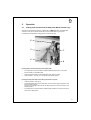
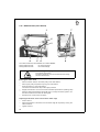
1.
Product description
The DÜRKOPP ADLER 69 is an all-purpose special sewing machine.
•
•
•
•
•
•
•
2.
Double-lockstitch free-arm machine with underfeed, needle feed and alternating
foot overfeed.
Depending on the subclass, a single-needle machine with or without thread clipper
beneath the needle plate.
Slim free arm with large passage space and large sewing-foot stroke.
Maximum passage space beneath raised sewing feet: 12 mm (with
sewing-foot-raising knee lever).
Small horizontal shuttle.
The sewing machine can be supplied with a closed, cut-out or fold-down left-hand
table-plate half. The fold-down version permits the unobstructed manipulation of
large items round the free arm.
Smooth, draw-free edging and precision sewing of inner and outer arcs by an
integral follow binder mechanism.
Knee-operated pneumatic rapid stroke-adjustment mechanism to switch the foot
overfeed to maximum sewing-foot stroke (optional extra).
Designated use
The 69 is a special sewing machine designed to be used to sew light to medium-heavy
materials. As a rule such material consists of textile or synthetic fibres, but it also
includes leather.
These materials are used in the clothing, footwear and leatherwear industries, as well
as in domestic and automobile upholstery.
This special sewing machine can also be used to execute so-called technical seams.
However, the operator must carry out an assessment of the possible dangers (with
which DÜRKOPP ADLER AG would be happy to assist), as such applications are
comparatively unusual and they are potentially of enormous diversity. Depending on the
outcome of this assessment it may be necessary to take special safety precautions.
Generally speaking material processed with this special sewing machine must be dry,
its thickness when compressed by the lowered sewing feet must not exceed 7 mm and
it must contain no hard objects, since otherwise the operator of the machine would have
to wear protective goggles (which cannot at present be supplied).
The seam is generally executed with textile-fibre sewing threads up to 30/3 NeB (cotton
yarns), 40/3 Nm (synthetic yarns) or 30/3 Nm (covering yarns) in size. The use of any
other threads must also be subject to an assessment of the risks involved and the
taking of any necessary safety precautions.
The premises in which this special sewing machine is set up and operated must be dry
and well-maintained. If it is to be used in premises which are not dry and
well-maintained, special precautions may be necessary: these must be the subject of
an agreement (see EN 60204-3-1:1990).
As manufacturers of industrial sewing machines we work on the assumption that
personnel working on our machines will be at least semi-skilled, so that they can be
presumed to be familiar with all normal operations and with the dangers inherent in
them.
5
3.
Subclasses
class 69-373:
class 69-FA-373:
3.1
Optional extras
order no.
optional extra
FLP 14-2
electro-pneumatic sewing-foot-raising mechanism
pedal-operated.
RAP 14-1
electro-pneumatic bar-tack and sewing-foot-raising mechanism
pedal-operated.
HP 11-1
Pneumatic rapid stroke-adjustment mechanism for the overfeed
knee-operated.
WE-6
Maintenance unit
For pneumatic optional extras.
0797 003031
Pneumatic connection pack
For the pneumatic connection of frames with the maintenance unit
and pneumatic optional extras.
Consisting of connecting hose (length 5 m, diameter 9 mm),
connectors, bands, coupler plug and socket.
9822 510001
Halogen lamp
WALDMANN, with 12V/20W bulb, attached to the upper part of the
machine.
0798 500088
Lamp transformer
For 230V, with mains connector, without switch,
for 9822 510125 and 9822 510001 lamps.
0707 487519
Lamp-attachment set
For 9822 510001 lamp.
4.
Technical data
Lc noise-level
indicator:
6
single-needle double-lockstitch free-arm sewing machine with
underfeed, needle feed and alternating-foot overfeed
as class 69-373, but with electromagnetic thread clipper beneath
the needle plate
workplace-related emission valuein accordance with
DIN 45635-48-A-1-KL2
Lc =
81 dB (A)
class:
stitch length:
sewing-foot stroke:
stitch rate:
material:
69-373, 69-FA-373
4 mm
3.2 mm
1700 [min-1 ]
double Skai 1.6 mm 900 g/m 2 DIN 53352
Needle system:
Needle thickness (depending on E no.)
134
[Nm]
110 - 130
[NeB]
[Nm]
[Nm]
30/3
40/3
30/3
[min -1 ]
[min -1 ]
2000
1700
maximum stitch length:
- forwards
- backwards
[mm]
[mm]
5
5
maximum sewing-foot stroke:
[mm]
7
maximum passage space beneath raised sewing feet:
- sewing foot raised by lifting lever
[mm]
- sewing foot raised by knee lever
[mm]
7
12
Maximum sewing-thread thicknesses:
- cotton
- synthetic endless
- covering yarn
stitch rate:
- maximum
- ex works
operating pressure:
[bar]
rated voltage:
dimensions:
- MG 53-3 frame (H x W x D)
- MG 56-2 frame (H x W x D)
working height:
- MG 53-3 frame [mm]
- MG 56-2 frame [mm]
weight (upper part only):
6
3 x 220-240 V, 50/60 Hz
3 x 380-415 V, 50/60 Hz
[mm]
[mm]
1540 x 1060 x 550
1560 x 1200 x 600
...
760 - 850
780
ca. [kg]
33
7
3
1
8
2
3
4
5.
Operation
5.1
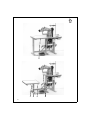
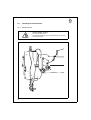
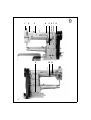
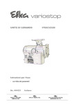
Folding down left-hand half of table plate (MG 56-2 frame only)
When the special sewing machine is fitted with the MG 56-2 frame the table plate
consists of two parts. The left-hand half 3 can be folded down to permit the
unobstructed manipulation of large items round the free arm.
5
3
7
6
8
Folding down the left-hand half of the table plate
–
Turn fasteners 7 and 8 beneath the table plate anticlockwise to unlock the
left-hand half 3 of the table plate.
–
–
Fold the left-hand half 3 of the table plate down and to the left.
Hook shackle 1 onto the pin 2 of the left-hand frame upright.
Folding the left-hand half of the table plate back into place
–
–
–
Unhook shackle 1 from pin 2.
Lift the left-hand half 3 of the table plate, swivel it to the right and lower it onto
support plates 5 and 6.
The pins 4 in the right-hand half of the table plate must fit into the holes in the
left-hand half 3.
Turn fasteners 7 and 8 beneath the table plate clockwise to lock the left-hand
half 3 of the table plate.
9
5.2
Threading the needle thread
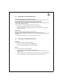
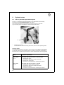
5.2.1
Subclass 69-373
Caution: danger of injury
Turn off the main switch
The needle thread may only be threaded with the sewing
machine turned off.
10
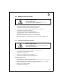
5.2.2 Subclass 69-FA-373
Caution: danger of injury
Turn off the main switch
The needle thread may only be threaded with the sewing
machine turned off.
11
1
2
3
12
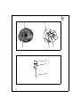
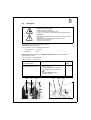
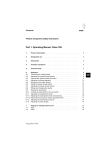
Fig. a:
correct thread loop in the centre
of the material
Fig. b:
needle-thread tension too weak or
looper-thread tension too strong
Fig. c:
needle-thread tension too strong
or looper-thread tension too weak
5.3
Adjusting the needle-thread tension
Pre-tensioning mechanism (subclass 69-FA-373)
On subclass 69-FA-373 the needle thread needs to be under residual tension for the
thread cutter to function reliably when the main tensioner 2 is open.
This residual tension is created by the pre-tensioning mechanism 1.
The pre-tensioning mechanism 1 also determines the length of the needle-thread end
after the thread has been clipped.
The pre-tension 1 should be set lower than the main tension 2.
–
–
Adjust pre-tensioning mechanism 1 by turning the knurled nut.
After major changes to preliminary tension 1 the main tension 2 should also be
adjusted accordingly.
Main tension
The main tension 2 should be set as low as possible.
The looping of the threads must be in the centre of the material (see fig. a).
With thin material excessive thread tension can cause unwanted gathering and thread
breakage.
–
5.4
Adjust the main tensioner 2 so that the stitches are uniform.
Opening the needle-thread tensioner
Automatic
The main tensioner 2 is opened automatically:
–
–
when the thread is severed (subclass 69-FA-373).
when the foot is raised (pedal 1 position backwards)
Manual
The main tensioner 2 is opened manually:
–
when the release lever 3 is pressed towards the arm.
The main tensioner 2 remains open for as long as pressure is maintained on the
release lever 3.
–
–
when the sewing feet are raised mechanically with the knee lever (see chapter 5.9).
when the sewing feet are locked in the raised position (see chapter 5.10).
13
1
2
3
4
5
9
8
6
14
7
8
7
10
11
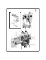
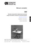
5.5
Winding on the looper thread
Caution: danger of injury
Turn off the main switch.
The looper thread may be threaded for winding on only
when the sewing machine is switched off.
–
When winding on for sewing with no underlay material:
arrest the sewing feet in the up position (see chapter 5.10).
–
–
–
–
Thread looper thread as shown in the upper illustration.
Wind about 5 coils of looper thread clockwise onto the bobbin core.
Place bobbin 3 on bobbin-winder shaft 5.
Swivel bobbin-winder lever 4 against the bobbin.
The bobbin-winder wheel 2 is pressed against the V-belt.
–
Adjust tension 1.
The looper thread should be wound on with minimal tension.
–
Sew.
The bobbin-winder lever 4 terminates the process as soon as the bobbin is full.
5.6
Fitting the looper-thread bobbin
Caution - danger of injury
Turn off the main switch.
The looper-thread bobbin may only be changed with the
sewing machine switched off.
Removing empty looper-thread bobbin
–
–
–
–
–
Turn handwheel until the needle bar reaches its highest position.
Pull off cap 6 in the direction of the arrow.
Raise bobbin-housing flap 8.
Remove top 7 of bobbin housing with bobbin.
Remove empty bobbin from top 7 of bobbin housing.
Threading looper thread
–
Place full bobbin 11 in top 7 of bobbin housing:
when the thread is wound off the bobbin 11 must rotate in the direction of the arrow.
–
Draw looper thread down through slit 10 under tensioning spring 9. Pull about 8
cm of looper thread out of the top 7 of the bobbin housing.
–
–
Replace top 7 of bobbin housing.
Close bobbin-housing flap 8.
15
1
3
2
4
6
7
8
16
5
5.7
Adjusting looper-thread tension
Caution: danger of injury
Turn off the main switch.
The looper-thread tension may only be adjusted with the
sewing machine switched off.
Adjusting brake spring 1 (class 69-FA-373)
On subclass 69-FA-373 the brake spring 1 prevents the bobbin from "running on" when
the machine halts or if the looper thread is wound off spasmodically.
–
–
Unscrew regulating screw 4 until no tension remains in tension spring 3.
Adjust brake spring 1 with regulating screw 5.
The braking force is correctly adjusted if brake spring 1 is about 1 mm above
surface 2.
Adjusting tension spring 3
–
Adjust tension spring 3 with regulating screw 4.
to increase looper-thread tension: turn screw clockwise
to reduce looper-thread tension: turn screw anticlockwise
For stitch formation see sketch a on page 12.
5.8
Fitting and changing the needle
Caution: danger of injury
Turn off the main switch.
The needle may only be changed with the sewing machine
switched off.
–
–
–
–
–
Turn the handwheel until the needle bar 6 reaches its highest position.
Undo screw 7.
Pull needle downwards out of needle bar 6.
Insert new needle as far as it will go into the hole in needle bar 6.
Caution:
When seen from the operating side of the machine the furrow 8 of the needle must
point to the rights(see sketch).
Tighten screw 7.
CAUTION:
When a thicker needle is fitted the distance from the
shuttle to the needle must bed corrected (see servicing
instructions).
Failure to comply with this instruction can cause the following faults:
when fitting a thinner needle:
faulty stitches, damage to thread
when fitting a thicker needle:
damage to the shuttle tip and needle
17
1
2
3
4
5
2
6
18
5.9
Lifting the sewing feet
The sewing feet are raised mechanically or electro-pneumatically, depending on which
mechanism is fitted to the machine.
Mechanical sewing-foot-raising mechanism (with the machine at a halt)
–
Operate knee lever 1.
The sewing feet remain raised as long as pressure is maintained on knee lever 1 [].
Electro-pneumatic sewing-foot-raising mechanism
(when FLP 14-2 or RAP 14-1 are fitted)
–
Push pedal half-way back.
The sewing feet are raised with the machine at a halt.
–
Push pedal all the way back.
The thread clipper is activated and the sewing feet raised.
5.10 Locking the sewing feet in the raised position
The mechanically or pneumatically raised sewing feet 3 are locked in the raised
position with lever 2 (e.g. for the looper thread to be wound on or the sewing foot
changed). Lever 2 is located on the back of the machine arm.
–
With the machine at a halt, swivel lever 2 up.
The sewing feet 3 are locked in the raised position.
–
Swivel lever 2 down.
The sewing feet are no longer locked.
5.11 Adjusting the sewing-foot stroke
The height of the sewing-foot stroke is determined by the position of tension bar 6.
Caution: danger of injury
Turn off the main switch.
The sewing-foot stroke may only be adjusted with the
sewing machine switched off.
Adjusting the sewing-foot stroke
–
–
–
Undo nut 4 on the back of the machine arm.
Push tension bar 6 into rocker lever 5.
tension bar fully up: maximum sewing-foot stroke (4.5 mm)
tension bar fully down: minimum sewing-foot stroke (2.5 mm)
Tighten nut 4.
19
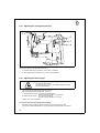
5.12 Adjusting the sewing-foot pressure
1
2
3
4
Sewing-foot pressure is adjusted with screw 1.
–
–
to increase sewing-foot pressure: turn screw 1 clockwise
to reduce sewing-foot pressure: turn screw 1 anticlockwise.
5.13 Adjusting the stitch length
Caution: danger of injury
Turn off the main switch.
The stitch length may only be adjusted with the sewing
machine switched off.
–
–
Turn wing-nut 2 anticlockwise as far as it will go.
–
Tighten wing-nut 2 clockwise.
Adjust the desired stitch length with screw 3.
To increase stitch length: turn screw 3 anticlockwise.
The stitch-length handle 4 moves down.
To reduce stitch length: turn screw 3 clockwise.
The stitch-length handle 4 moves up.
To sew bar tacks manually (backwards sewing):
–
20
Swivel the stitch-length handle 4 up as far as it will go (to position "R").
The machine sews backwards as long as the stitch-length handle 4 is held up.
5.14 Welting
1
3
2
4
The rapid-adjustment welt-guide mechanism with three positions is used to sew welts
between two layers of material. It can be swivelled in or out at the beginning and end of
the seam.
Four welt guides 2 are available (sewing attachments E20 - E23) with welt grooves from
3 to 6 mm.
Caution: danger of injury
Turn off the main switch.
The welt may only be inserted with the sewing machine
switched off.
Inserting the welt
–
–
–
–
Undo screw 1.
Feed welt in through welt guide 2.
Adjust welt guide 2 to the width of the welt.
The welt must be guided at the sides, but at the same time it must be easy to pull it
through the welt guide 2.
Tighten screw 1.
Sewing in the welt
–
–
–
–
–
Lay the welt between the two layers of material.
Pull out ball handle 4 and turn lever 3 as far as it will go to the left (position P).
Start sewing until the needle has reached approximately the middle of the welt.
To continue sewing in the welt pull out ball handle 4 and turn lever 3 to the centre
position (position S), where it engages.
At the end of the seam pull out ball handle 4 and turn lever 3 to its basic position
(position 0).
21
5.15 Ribbon binder (class 69-373)
1
7
2
3
4
5
6
8
Two ribbon-binder sets are available for subclass 69-373:
sewing attachment E4:
for narrow bindings
sewing attachment E5:
for broad bindings
Caution: danger of injury
Turn off the main switch.
The ribbon band may only be inserted with the sewing
machine switched off.
Inserting the ribbon band
–
–
–
Place the ribbon band on the lower pulley of the reel holder 3.
–
–
Slightly raise the arm cover 6 and swivel it forwards (towards the operating side).
–
Swivel the arm cover 6 back into place.
Place upper pulley and pressure spring 2 on reel holder 3.
Screw knurled nut 1 onto reel holder 3.
The ribbon band should be kept under slight pressure.
Pass the ribbon band between the guide pins 5, through the ribbon guide 4, into
the ribbon binder 8 and under the sewing feet.
Adjusting the distance of the seam from the ribbon edge
–
–
Undo screws 7.
–
Tighten screws 7.
22
Adjust the distance of the seam from the ribbon edge as required by moving the
ribbon binder 8.
6.
Control unit and operating panel
CAUTION:
These operating instructions describe only the functions of
the buttons and the change of parameters by the operator.
For a detailed description of the control unit please see the
current operating instructions of the motor manufacturer
(supplied).
6.1
General
The control unit is programmed and the seam functions set with the control-unit buttons
or the operating panel (for programming see motor manufacturer’s manual).
Depending on the seam required, sewing can be executed manually or by
seam-programming (only with the operating panel).
Three different seam cycles can be programmed for various sewing requirements, in
which the various functions (starting bar tack, ending bar tack, stitch count, thread
cutting etc.) and parameter values (stitch rate, seam length, rpm etc.) are individually
assigned.
Entry is carried out in programming mode.
The parameters and the values assigned are displayed.
The seam programs are not lost even when the sewing machine is switched off (battery
buffer).
In order to avoid the inadvertent alteration of pre-set functions, operation is divided into
various levels (operator, technician).
The operator (seamstress) can program directly.
Access to the technician level is contingent on the entry of a code number (EFKA) or on
switching on the main switch by simultaneously holding down two buttons (QUICK).
RESET
If the control unit is hopelessly misadjusted, this function allows the technician to reset
all adjusted values to their default (ex-works) settings.
This function is described in the Servicing instructions.
23
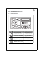
6.2
Efka VD554KV/6F82AV sewing drive
6.2.1
Control-box buttons
In programming mode
button
24
function
P
programming mode (start / end)
E
confirm parameter-value change
switch to next parameter
+
increase displayed parameter value
switch to next parameter
increase code no.
-
reduce displayed parameter value
switch to last parameter
reduce code no.
>>
select next character in display
Button functions in sewing mode
button
function after the thread has been clipped
LED display
select programming mode
starting bar tack
- single *
- double *
- OFF
ending bar tack
- single *
- double *
- OFF
Automatic sewing-foot-raising mechanism
- when stopping in mid-seam
- at the end of the seam
- when stopping in mid-seam and at the end of
the seam
- OFF
Basic needle position
- up
- down
* Starting and ending bar tacks cannot be sewn with this machine.
CAUTION:
The + and - buttons increase or reduce the maximum rpm
before the thread is clipped.
25
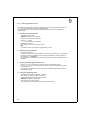
6.2.2
Altering parameter values
Parameter values are altered at operator level with the five buttons "P", "E", "+", "-" and
">>" on the sewing-drive control box.
The parameter list on the next page gives all parameters which can be altered at
operator level.
1. Selecting programming mode
- Press the "P" button.
The first parameter number (0 0 0) appears in the display.
2. Displaying the first operator-level parameter
- Press the "E" button.
The appropriate parameter value (0. 0. 0.) appears in the display.
3. Changing the displayed parameter value
- Increase or reduce the parameter value with the "+" and "-" buttons.
If the "+" or "-" button is held down, the parameter value continues to change until
it is released.
4. Selecting the next parameter value
- Press the "E" button.
The next operator-level parameter appears in the display.
- Press the "E" button.
The appropriate parameter value appears in the display.
Repeatedly pressing the "E" button successively calls up all operator-level parameters and parameter values.
When the parameter is displayed the + or - buttons can also be used to switch to
the next or previous parameter.
5. Leaving programming mode
- Press the "P" button.
The control unit leaves programming mode.
CAUTION:
The changed parameter values are not saved until a seam
is started by pressing the pedal down.
If the sewing machine is switched off immediately after
programming without sewing, the changed parameter
values are not saved.
26
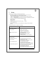
"Operator-level" parameter list:
Parameter
function
setting
max.
min.
ex works
000
*
starting bar-tack stitches forwards
254
0
2
001
*
starting bar-tack stitches backwards
254
0
4
002
*
ending bar-tack stitches backwards
254
0
2
003
*
ending bar-tack stitches forwards
254
0
2
004
*
light-barrier compensation stitches
254
0
7
005
*
light-barrier filter stitch rate
for knitted yard goods
254
0
0
006
*
number of light-barrier seams
15
1
1
254
0
20
3
1
1
007
seam stitch rate with stitch count
008
assigning ato the "3" button
technician-level parameters
(only when operating the control unit
with a Variocontrol operating panel)
1 = softstart ON / OFF
2 = ornamental-stitch bar tack ON/OFF
3 = sewing-on with light barrier light
blocked ON / OFF
009
*
light barrier ON / OFF
013
*
thread clipper ON / OFF
ON
014
*
thread retractor ON / OFF
ON
015
stitch count
OFF
OFF
* this parameter is vacant on this machine class
27
6.3
Quick QD554/A51K01 sewing drive
6.3.1
Operating-panel buttons
button
28
function
in programming mode
select programming mode
(in conjunction with "-" button)
leave programming mode
(in conjunction with "-" button)
suppress starting / ending bar tack
switch to next parameter
number
single depression: sew 1 stitch
held down:
sew at n min
increase displayed value
change program
(MANUALLY - SEAM-A - SEAM-B)
reduce displayed value
button
function
ornamental bar tack
normal bar tack
starting double bar tack
starting single bar tack
starting bar tack on
starting bar tack off
sewing-foot position up before thread clipping
sewing-foot position down before thread clipping
ending bar tack double
ending bar tack single
ending bar tack on
ending bar tack off
smooth seam start
normal seam start
vacant
29
6.3.2
Altering parameter values
A operator level parameter values are changed with the four program buttons ("G", "F",
"+", "-") on the right-hand side of the operating panel.
The parameter list on the next page gives all parameters which can be altered at
operator level.
1. Selecting programming mode
- Turn on the main switch.
"MANUAL" appears in the display.
- Press and hold down the "G" button.
- Press the "-" button.
"- - - - - - >F" appears in the display.
- Release both buttons.
The control unit is in programming mode.
NB:
The sewing drive is inoperative in programming mode.
2. Selecting parameter number
- Press the "G" button.
The button must be pressed repeatedly until the group number (e.g. 6xx) appears.
- Press the "F" button repeatedly until the required parameter number appears in
the display (e.g. "102*0002").
If the "F" button is held down the parameter number continues to change until it is
released.
3. Changing the displayed parameter value-
- Use the "+" and "-" buttons to increase or reduce the parameter value.
If the "+" or "-" button is held down the parameter number continues to change until it is released.
- If you leave the parameter-number routine the last-displayed parameter value is
automatically saved.
4. Leaving programming mode
- Simultaneously press the "G" and "-" buttons.
The control unit leaves programming mode.
The last-displayed parameter value is saved.
- "MANUAL" appears in the display.
- The control unit is ready for use.
The new settings can be checked by executing a test seam.
30
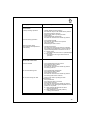
"Operator-level" parameter list:
parameter
function
setting
min.
max.
ex works
101
switch between seam programs
(the "P" button executes the switch)
MAB: MANUAL - SEAM-A - SEAM-B
M+A: MANUAL - SEAM-A
M+B: MANUAL - SEAM-B
A+B:
SEAM-A - SEAM-B
MAB
102
starting bar tack - stitch rate forwards
0
255
2
103
starting bar tack - stitch rate backwards
0
255
1
108
ending bar tack - stitch rate backwards
0
255
2
109
ending bar tack - stitch rate forwards
0
255
1
111*
light-barrier compensation stitches
0
30
1
201
stitch rate of seam section A
0
255
20
301
stitch rate of seam section B1
0
255
10
302
stitch rate of seam section B2
0
255
10
303
number of seam sections B1 and B2
0
255
2
505
starting ornamental bar tack - stitch
rate forwards
0
30
3
506
starting ornamental bar tack - stitch
rate backwards
0
30
3
507
ending ornamental bar tack - stitch
rate backwards
0
30
3
508
ending ornamental bar tack - stitch
rate forwards
0
30
3
521
needle position before thread clipping
(I = up, II = down)
I
II
II
* this parameter is vacant on this machine class
31
7.
Sewing
This description is based on the following assumptions:
–
the machine in question is a special sewing machine with thread clipper
(subclass 69-FA-373) and the following optional extras:
- RAP 14-1 electro-pneumatic bar-tack and sewing-foot-raising mechanism,
pedal-operated
- HP 11-1 pneumatic rapid stroke-adjustment mechanism, operated by a knee lever
–
The following functions are set at the operating panel:
starting bar tack:
ON
ending bar tack:
ON
sewing-foot position before and after clipping:
DOWN
–
–
The main switch is on.
The last sewing operation was concluded with an ending bar tack and thread
clipping.
Operating and function sequence for sewing:
sewing operation
operation / explanation
Before starting sewing
starting position
- pedal in neutral position
the machine is at a standstill
needle up - sewing feet down
position material at start of
seam
- move pedal back and hold it there
the sewing feet rise
- place material under the needle
- release the pedal
the sewing feet lower onto the material
At start of seam
sew starting bar tack and
continue sewing
- move pedal forward and hold it there
starting bar tack is sewn
the machine then continues sewing at the
motor speed set by the pedal
sew only starting bar tack
- move pedal briefly forwards
the machine stops after sewing the
starting bar tack in the needle-down position
do not sew starting bar tack
- press "F" button (suppress starting bar tack)
- move pedal forward and hold it there
the machine then sews at the
motor speed set by the pedal
- the next seam is begun with a starting bar tack
32
sewing operation
operation / explanation
In mid-seam
interrupt sewing operation
- release pedal (neutral position)
the machine stops in the needle-down position
the sewing feet are lowered
- press the "F" button (ending bar-tack
suppression)
- move pedal briefly backwards
the machine assumes the needle-up position
resume sewing operation
- move pedal forwards
the machine sews at the motor speed
set by the pedal
no starting bar tack is sewn
sew transverse seam
(with rapid stroke-adjustment
mechanism)
- operate knee switch
the maximum sewing-foot stroke is activated
the operating time depends on what mode the
rapid stroke-adjustment mechanism is set to:
a) switch mode:
- activated until knee switch is operated again
b) key mode:
- activated for as long as knee switch is
operated
At the end of the seam
remove material
- move pedal back and hold it there
the ending bar tack is sewn
the thread is severed
the machine assumes the needle-up position
the sewing feet rise
do not raise sewing feet
- move pedal briefly backwards
the ending bar tack is sewn
the thread is severed
the machine assumes the needle-up position
the sewing feet remain lowered
do not sew ending bar tack
- press the "F" button (ending bar-tack
suppression)
- move pedal back
the ending bar tack is not sewn
the thread is severed
the machine assumes the needle-up position
the position of the sewing feet depends on the
position of the pedal:
a) pedal pressed backwards and held:
- sewing feet raised
b) pedal released (in neutral position):
- sewing feet lowered.
33
8.
Maintenance
Caution: danger of injury
Turn off the main switch!
Maintenance work may only be carried out on the sewing
machine when it is switched off.
Maintenance work must be carried out no less frequently than at the intervals given in
the tables (see "operating hours" column).
Maintenance intervals may need to be shorter when processing heavy-shedding
materials.
8.1
Cleaning and testing
A clean sewing machine is a trouble-free sewing machine.
6
4
8
2
10
1
2
3
34
maintenance work
to be carried out
explanation
operating
hours
Upper part of machine
- Remove lint, pieces of
thread and other debris.
Places in special need of cleaning:
- area under the needle plate
- feeder
- area around the shuttle
- bobbin housing
- needle-thread tensioner
- thread clipper (class 69-FA-373)
8
Sewing drive
- Check the condition and
tension
of the V-belt.
It must be possible to depress the V-belt
by about 10 mm by pressing on it with a
finger at its mid-point.
160
The water level must not reach
the filter insert 2.
- After screwing in the drain plug 3 blast
the water out of the water separator
under pressure.
40
Compressed-air
maintenance
unit (optional extra)
- Check the water level in
the pressure regulator.
NB:
The water separator 2 is fitted with a
semi-automatic condensation drain.
Condensation is automatically drained
when the pressure falls below a pre-set
level.
- Clean the filter insert.
Dirt and condensation are separated by
filter insert 1.
- Disconnect the machine from the
compressed-air supply.
- Screw in drain plug 3.
There must be no pressure in the
machine’s pneumatic system.
- Unscrew water separator 2.
- Unscrew filter insert 1
Wash the filter shell and insert
with cleaning fluid (not solvent)
and blast clean.
- Re-assemble and connect the
maintenance unit.
500
35
1
2
3
4
9
36
5 6 7 8
10 11
8.2
Lubrication
Caution: danger of injury
Oil can cause skin eruptions.
Avoid protracted contact with the skin.
In the event of contact, thoroughly wash the affected area.
CAUTION:
The handling and disposal of mineral oils is subject to legal
regulation.
Deliver used oil to an authorised collection point.
Protect your environment.
Take care not to spill oil.
To lubricate the special sewing machine use only
ESSO SP-NK 10 lubricating oil
or an equivalent oil of the following specification:
–
–
viscosity at 40° C :
flashpoint:
10 mm 2 /s
150 °C
ESSO SP-NK 10 is available from DÜRKOPP ADLER AG retail outlets under the
following part numbers:
2-litre container:
9047 000013
5-litre container:
9047 000014
maintenance work
to be carried out
explanation
oil lubrication points 1 to 17
- Remove the top.
- Oil all the lubrication points shown
in the illustration with a few drops
of oil.
NB:
Subclass 69-FA-373 has no
lubrication point 8.
12
13
14
operating
hours
15
16
40
17
37
9.
Optional extras
9.1
HP 11-1 pneumatic rapid stroke adjuster
The HP 11-1 pneumatic rapid stroke adjuster is only available for special sewing
machines with the Quick QD554/A51K01 sewing drive.
This optional extra allows a larger sewing-foot stroke to be set in mid-seam
(e.g. for thicker pieces of material or to oversew transverse seams).
1
–
Operate knee switch 1.
This activates the maximum sewing-foot stroke, which has two operating modes.
Operating modes
The rapid stroke-adjustment mechanism can be used in either switch or touch mode.
The desired operating mode is determined by the setting of parameter number 401 at
technician level - see servicing instructions or motor manufacturer’s manual (supplied).
mode
operation / explanation
switch mode
activated until the knee switch is operated again
401 = I
- Operate knee switch.
The maximum sewing-foot stroke is activated.
- Operate knee switch again.
The seam is continued with the set sewing-foot stroke.
touch mode
401 = II
activated until the knee switch is released
- Operate knee switch and hold it in place.
The maximum sewing-foot stroke is activated.
- Release knee switch.
The seam is continued with the set sewing-foot stroke.
38