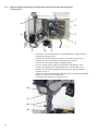
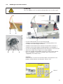
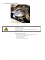
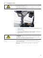
1
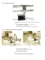
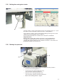
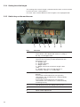
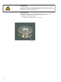
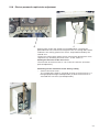
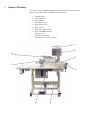
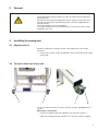
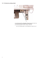
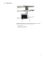
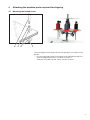
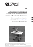
550-867
Operating Instructions
Foreword
This instruction manual is intended to help the user to become familiar
with the machine and take advantage of its application possibilities in
accordance with the recommendations.
The instruction manual contains important information on how to
operate the machine securely, properly and economically. Observation
of the instructions eliminates danger, reduces costs for repair and
down-times, and increases the reliability and life of the machine.
The instruction manual is intended to complement existing national
accident prevention and environment protection regulations.
The instruction manual must always be available at the machine/sewing
unit.
The instruction manual must be read and applied by any person that is
authorized to work on the machine/sewing unit. This means:
–
–
–
Operation, including equipping, troubleshooting during the work
cycle, removing of fabric waste,
Service (maintenance, inspection, repair) and/or
Transport.
The user also has to assure that only authorized personnel work on the
machine.
The user is obliged to check the machine at least once per shift for
apparent damages and to immediatly report any changes (including the
performance in service), which impair the safety.
The user company must ensure that the machine is only operated in
perfect working order.
Never remove or disable any safety devices.
If safety devices need to be removed for equipping, repairing or
maintaining, the safety devices must be remounted directly after
completion of the maintenance and repair work.
Unauthorized modification of the machine rules out liability of the
manufacturer for damage resulting from this.
Observe all safety and danger recommendations on the machine/unit!
The yellow-and-black striped surfaces designate permanend danger
areas, eg danger of squashing, cutting, shearing or collision.
Besides the recommendations in this instruction manual also observe
the general safety and accident prevention regulations!
General safety instructions
The non-observance of the following safety instructions can cause
bodily injuries or damages to the machine.
1. The machine must only be commissioned in full knowledge of the
instruction book and operated by persons with appropriate training.
2. Before putting into service also read the safety rules and
instructions of the motor supplier.
3. The machine must be used only for the purpose intended. Use of
the machine without the safety devices is not permitted. Observe all
the relevant safety regulations.
4. When gauge parts are exchanged (e.g. needle, presser foot, needle
plate, feed dog and bobbin) when threading, when the workplace is
left, and during service work, the machine must be disconnected
from the mains by switching off the master switch or disconnecting
the mains plug.
5. Daily servicing work must be carried out only by appropriately
trained persons.
6. Repairs, conversion and special maintenance work must only be
carried out by technicians or persons with appropriate training.
7. For service or repair work on pneumatic systems, disconnect the
machine from the compressed air supply system (max. 7-10 bar).
Before disconnecting, reduce the pressure of the maintenance unit.
Exceptions to this are only adjustments and functions checks made
by appropriately trained technicians.
8. Work on the electrical equipment must be carried out only by
electricians or appropriately trained persons.
9. Work on parts and systems under electric current is not permitted,
except as specified in regulations DIN VDE 0105.
10. Conversion or changes to the machine must be authorized by us
and made only in adherence to all safety regulations.
11. For repairs, only replacement parts approved by us must be used.
12. Commissioning of the sewing head is prohibited until such time as
the entire sewing unit is found to comply with EC directives.
13. The line cord should be equipped with a country-specific mains
plug. This work must be carried out by appropriately trained
technicians (see paragraph 8).
It is absolutely necessary to respect the safety
instructions marked by these signs.
Danger of bodily injuries !
Please note also the general safety instructions.
Index
Page:
Preface and General Safety Instructions
Part 1: Operating Instructions Class 550-867 – Original Instructions
(Edition 12/2011)
1
Product Description . . . . . . . . . . . . . . . . . . . . . . . . . . . . . . . . . . . . . . . . . . .
5
2
Designated Use . . . . . . . . . . . . . . . . . . . . . . . . . . . . . . . . . . . . . . . . . . . . . .
8
3
Optional Equipment . . . . . . . . . . . . . . . . . . . . . . . . . . . . . . . . . . . . . . . . . . .
8
4
Technical Data . . . . . . . . . . . . . . . . . . . . . . . . . . . . . . . . . . . . . . . . . . . . . .
9
5
5.1
5.1.1
5.1.2
. . . . . . . . . . . .
. . . . . . . . . . . .
10
11
5.2
5.3
5.4
5.5
5.6
5.7
5.8
5.9
5.10
5.11
5.12
5.13
5.14
5.15
5.16
5.17
5.18
5.19
5.20
Operating
Threading the needle thread . . . . . . . . . . . . . . . . . . . . . . . . . . .
Machines with electronically controlled needle thread tension (ETT) . . .
Machines with mechanically set needle thread tension and with
electromagnetic tension release. . . . . . . . . . . . . . . . . . . . . . . . .
Adjusting the needle-thread tension (mechanically) . . . . . . . . . . . . .
Adjusting the needle-thread tension (ETT). . . . . . . . . . . . . . . . . . .
Adjusting the thread regulator . . . . . . . . . . . . . . . . . . . . . . . . . .
Winding on the hook thread . . . . . . . . . . . . . . . . . . . . . . . . . . .
Threading in the hook thread. . . . . . . . . . . . . . . . . . . . . . . . . . .
Inserting the hook thread bobbin with machines equipped with residual
Setting the hook thread tension . . . . . . . . . . . . . . . . . . . . . . . . .
Changing the needle. . . . . . . . . . . . . . . . . . . . . . . . . . . . . . . .
Lifting the sewing feet . . . . . . . . . . . . . . . . . . . . . . . . . . . . . . .
Locking the sewing feet in lifted position . . . . . . . . . . . . . . . . . . .
Setting the sewing-foot stroke. . . . . . . . . . . . . . . . . . . . . . . . . .
Sewing-foot pressure . . . . . . . . . . . . . . . . . . . . . . . . . . . . . . .
Setting the stitch length. . . . . . . . . . . . . . . . . . . . . . . . . . . . . .
Switch-key on the machine arm . . . . . . . . . . . . . . . . . . . . . . . . .
LEDs on the tension plate . . . . . . . . . . . . . . . . . . . . . . . . . . . .
Residual-thread monitor RFW 20 – 7 . . . . . . . . . . . . . . . . . . . . . .
Electro-pneumatic rapid stroke adjustment . . . . . . . . . . . . . . . . . .
Uninterruptible power supply (UPS) . . . . . . . . . . . . . . . . . . . . . .
Sewing lamp . . . . . . . . . . . . . . . . . . . . . . . . . . . . . . . . . . . .
. . . . . . . . . .
. . . . . . . . . .
. . . . . . . . . .
. . . . . . . . . .
. . . . . . . . . .
. . . . . . . . . .
thread monitor.
. . . . . . . . . .
. . . . . . . . . .
. . . . . . . . . .
. . . . . . . . . .
. . . . . . . . . .
. . . . . . . . . .
. . . . . . . . . .
. . . . . . . . . .
. . . . . . . . . .
. . . . . . . . . .
. . . . . . . . . .
. . . . . . . . . .
. . . . . . . . . .
.
.
.
.
.
.
.
.
.
.
.
.
.
.
.
.
.
.
.
.
.
.
.
.
.
.
.
.
.
.
.
.
.
.
.
.
.
.
.
.
12
13
13
14
15
16
17
18
19
20
20
21
21
22
22
25
25
27
28
28
6
6.1
6.1.1
6.1.2
6.1.3
6.2
Operating the tearing seam visualization
Accessing the system . . . . . . . . . . . . . .
Logging in with scanner and barcode . . . .
Logging in via the menu. . . . . . . . . . . . .
Logging out of the system . . . . . . . . . . .
Exiting the program . . . . . . . . . . . . . . .
.
.
.
.
.
.
.
.
.
.
.
.
.
.
.
29
29
30
31
32
.
.
.
.
.
.
.
.
.
.
.
.
.
.
.
.
.
.
.
.
.
.
.
.
.
.
.
.
.
.
.
.
.
.
.
.
.
.
.
.
.
.
.
.
.
.
.
.
.
.
.
.
.
.
.
.
.
.
.
.
.
.
.
.
.
.
.
.
.
.
.
.
.
.
.
.
.
.
.
.
.
.
.
.
.
.
.
.
.
.
.
.
.
.
.
.
.
.
.
.
.
.
.
.
.
.
.
.
.
.
.
.
.
.
.
.
.
.
.
.
.
.
.
.
.
.
.
.
.
.
Index
Page:
7
7.1
Sewing
Seam scanner (optional) . . . . . . . . . . . . . . . . . . . . . . . . . . . . . . . . . . . . . . . . .
36
8
8.1
8.2
Maintenance
Cleaning and Checking . . . . . . . . . . . . . . . . . . . . . . . . . . . . . . . . . . . . . . . . . .
Repair . . . . . . . . . . . . . . . . . . . . . . . . . . . . . . . . . . . . . . . . . . . . . . . . . . . .
37
39
1
Product Description
The DÜRKOPP ADLER class 550-867 is a sewing unit designed for
documented airbag tearing seams.
Single needle flat bed double lockstitch sewing machine class 867
with bottom feed, needle feed and alternating upper feed.
With electromagnetic actuated thread trimmer and sewing foot lifting.
Electromotor driven stitch length setting and seam bartacking.
Technical specifications sewing unit
·
·
·
·
·
·
·
·
·
·
·
·
·
·
·
·
·
·
·
·
·
·
·
Extra-large, two-piece vertical hook (XXL)
The maximum fabric clearance underneath the sewing feet is
20 mm.
The remaining thread length after thread trimming is about 7 mm
with a short thread trimmer equipment.
The snap fit coupling prevents the displacing and damaging of the
hook at thread deflection
Automatic wick lubricating with an inspection glass on the arm for
the machine and hook lubrication.
Stitch length setting via step motor
Multi-position cylinder for the adjustment of the sewing-foot
stroke
Rapid stroke adjustment with automatic speed adaption
Electronically controlled needle thread tension (ETT= electronic
controlled needle thread tension)
or
mechanically set needle thread tension and with electromagnetic
tension release
Residual thread monitor RFW 20–7
Thread tension sensor
Motor driven bobbin winder with automatic wind on
Specially designed bobbin in order to prevent errors through the
insertion of inadequate bobbins
Stand is adjustable in height
Monitoring of the throat plate slide at bobbin change
Fabric edge guide with integrated glass fibre optics light barrier in
order to recognize the strip on the cuts and LED to recognize the
seam segment (tearing seam = red, free seam = green)
Upper feed pressure can be locked
Barcode printer
15" industrial touch panel PC
Needle and hook thread cone monitoring via proximity switch
Manual scanner
Log in system via manual scanning
Reel stand for 6 thread cones
5
Technical specifications software
·
·
·
·
·
·
·
·
·
·
·
·
·
·
·
·
·
·
·
·
·
6
Intuitive user interface
Sewing programs with up to 30 seam segments
Switching over via strip detection, stitch counting or manually
Different setup masks and endlabel masks can be memorized
Teach-in function for ETT (electronically controlled needle thread
tension)
Test window for the thread tension
Display of the thread tension during sewing
Recognition of the needle and hook thread via barcode scanning
(if the option is available)
Recognition of the material part 1 and / or part 2 (resp. part 3) via
manual scanning
Alle seam sections can be defined with various parameters
The following parameters are automatically suppressed in the
rupture seam segment
·
·
·
RS function (bartacking via step motor)
HP function (pneumatic stroke adjustment)
FA function (thread trimmer)
Optical indicator “tearing seam” in the visual field of the operator
(LED - red)
Evaluation of the collected material data
Monitoring and active adjustment of the needle tread tension (only
ETT (electronically controlled needle thread tension))
Automatic thread breakage recognition
Deviations from the nominal values during a seam are recognized
and lead to a sewing stop
The sewing process can be stopped in the segment of the lateral
airbag by the seamstress.
In order to do this the “FA” button has to be pressed and
additionally the foot pedal has to be pushed into position 2.
The message “not O.K.” will be automatically issued for this seat.
After completing the last seam section all sewing parameters will
be memorized and the request to scan the next material bar codes
appears
Data entry in a data base or in a ASCII file
Different levels authorized for operators, supervisors and
production manager
Data backup also during power outage via UPS (Uninterruptible
power supply)
Data entry
·
·
·
·
·
·
·
·
·
·
·
·
·
·
·
·
·
·
·
·
·
·
·
·
·
·
Date
Time
Line number
Endlabel barcode
Entrance barcode 1 - 3
Barcode needle thread
Barcode hook thread
Additional barcode information (max. 9)
Bobbin number
Bobbin winder information
Bobbin insertion information
Operator name
Number of seam sections
Set stitch length per seam section
Absolute seam section length
Calculated stitch length
Thread tension window
Stitch counting
Name of seam pattern
Machine number
Manufacturer’s identification number
Cycle time
Error code
Cycle number
Thread tension data for individual stitches
Daily number
7
2
Designated Use
The class 550-867 is an configured sewing station designed for the
sewing of light to medium-heavy material. Such material is generally
made of textile fibers, but it may also be leather.
These materials are used in the clothing industry and for domestic and
motor-vehicle upholstery.
It is also possible to produce so-called technical seams with this
configured sewing station. In this case, however, the operator must
assess the possible dangers which may arise (DÜRKOPP ADLER AG
would be happy to assist with this assessment), since such
applications are on the one hand relatively unusual and, on the other,
so varied that no single set of criteria can cover them all. The outcome
of this assessment may require to take appropriate safety measures.
Generally only dry material may be sewn with this sewing machine.
The material must not be thicker than 10 mm when compressed by the
lowered sewing feet. The material may not contain any hard objects.
Otherwise the machine may only be operated with an eye-protection
device. Such an eye-protection device is currently not available.
The seam is commonly sewn with sewing threads made from textile
fibers of the dimensions up to 11 / 3 NeB (cotton threads), 11 / 3 Nm
(synthetic threads) or 11 / 4 Nm (core threads). If other types of thread
are to be used, the possible dangers arising from it have to be
assessed and, if necessary, safety measures have to be taken.
This configured sewing station may be set up and operated only in
dry, well-maintained premises. If the sewing unit is used in premises
which are not dry and well-maintained, it may be necessary to take
further precautions which should be agreed in advance (see
EN 60204-31:1999).
As manufacturers of industrial sewing machines we proceed on the
assumption that personnel that works on our products will have
received training at least sufficient to acquaint them with all normal
operations and with any hazards which these may involve.
3
Optional equipment
For the class 550-867 the following optional equipment is available:
Order-No.
Optional equipment
9800 330010
0867 590724
0867 590904
Control panel V 820
Head cover scanner incl. holder to check the endlabel
Scanner with holder (2x) to enter the needle- and hook
thread cone bar codes
Scanner (2x) for the bobbin monitoring via barcode on
the bobbin winder and hook
Needle cooling NK 20-1
Needle cooling NK 20-5
0867 590924
0867 590014
0867 590054
8
4
Technical data
Noise:
Lc = dB (A)
Workplace-related emission value in accordance with
DIN EN ISO 10821
Speed: min -1
Material:
Sewing stitch type:
301 / double lock stitch
Number of needles:
1
Needle system:
134/35
Needle size :
Needle thread size
- Cotton:
- Synthetic sewing thread:
- Core thread
Bobbin wind-on capacity with
synthetic sewing thread
- 60/3:
Number of stitches:
- with HP equipment:
- factory setting:
[NM]
90 - 140
[NeB]
[Nm]
[Nm]
20/3
20/3
20/3
[m]
98
[min ]
[min ]
3400
3400
Stitch length:
Forwards and backwards
[mm]
0 - 6 (9)
Lift stroke of sewing feet:
- max.
[mm]
9
Clearance underneath sewing feet
- Sewing
[mm]
- Lifted:
[mm]
10
20
Operating pressure:
6
Air consumption:
- 1
- 1
[bar]
about [NL]
Length, width, height (incl. PC)
Weight:
Rated voltage:
Input power:
[mm]
[kg]
0.7
1600 x 920 x 1550
about 194
[V, Hz]
1~ 190 - 240 V, 50/60 Hz
[KVA]
1 kVA
9
5
Operating
5.1
Threading the needle thread
Caution: Risk of Injury !
Turn off the main switch!
The needle thread may only be threaded with the sewing machine
being switched off.
3
2
1
5
4
Before putting in the needle thread cones they need to be scanned
with the hand scanner.
With thread barcode scanner equipment (optional):
– Unscrew the ball 1.
– Put the cone 2 on the stand and make sure that the barcode 4 on
the thread reel can be read by the optional thread barcode
scanner 5.
If the scanner does not recognize the barcode an error message
will appear on the monitor.
– Tighten the reel with ball 1 and washer 3.
– Lead the needle thread through the unwinder arm 6.
The unwinder arm must be in vertical position above the thread
reels.
– Conduct the needle thread through the guiding tube 7.
7
10
6
5.1.1
Machines with electronically controlled needle thread tension (ETT)
1
2
9
8
3
4
7
6
–
–
–
–
–
–
–
–
5
Conduct the thread through the threading guide 1 and clockwise
around the pretensioner 2.
Conduct the thread counter-clockwise around the tensioner 3.
Conduct the thread clockwise around the tensioner 4.
Conduct the thread through threading guide 5.
Pull the thread underneath the thread take-up spring 7 and
conduct it through the thread regulator 6 to the thread lever 9.
Conduct the thread through the thread lever 9 and the thread
tension sensor 8.
Conduct the thread through the thread clamp 10 and the threading
guides 11 and 12 on the needle bar.
Thread the thread into the needle eye 13.
10
11
12
13
11
5.1.2
Machines with mechanically set needle thread tension and with electromagnetic
tension release
1
9
2
8
3
4
7
6
–
–
–
–
–
–
–
–
10
11
12
13
12
5
Conduct the thread through the threading guide 1 and clockwise
around the pretensioner 2.
Conduct the thread counter-clockwise around the tensioner 3.
Conduct the thread clockwise around the tensioner 4.
Conduct the thread through threading guide 5.
Pull the thread underneath the thread take-up spring 7 and
conduct it through the thread regulator 6 to the thread lever 9.
Conduct the thread through the thread lever 9 and the thread
tension sensor 8.
Conduct the thread through the thread clamp 10 and the threading
guides 11 and 12 on the needle bar.
Thread the thread into the needle eye 13.
5.2
Adjusting the needle-thread tension (mechanically)
1
2
3
4
The tension is to be set according to the values given by the seat
cover manufacturers. The cross-over point should lie in the center of
the material.
– The pretensioner 1 is preset.
– Unscrew the locking plate 3.
– Set the main tensioner 2 and 4.
– Mount the locking plate 3 again.
5.3
Adjusting the needle-thread tension (ETT)
The thread tension is set via the machine’s software.
13
5.4
Adjusting the thread regulator
3
2
1
Caution: Risk of injury!
Turn off the main switch.
The thread regulator may only be adjusted with the sewing machine
switched off.
The thread regulator 1 controls the quantity of needle thread required
for stitch formation.
The thread regulator must be precisely adjusted for an optimum result.
With correct setting the needle-thread loop must slide with low
tension over the thickest point of the hook.
– Loosen screw 2.
– Adjust position of the thread regulator 1.
Thread regulator to the left = more thread
Thread regulator to the right = less thread
– Tighten screw 2.
Adjustment information:
If the maximum quantity of thread is required, the thread-tensioning
spring 3 must be pulled upwards about 0.5 mm from its lower limit
position. This is the case, when the needle-thread loop passes the
maximum hook diameter.
14
5.5
Winding on the hook thread
ATTENTION!
Only use bobbins that are specially designed for this machine type!
3
2
–
–
–
–
–
–
–
6
5
4
1
Put the hook thread cone on the thread stand.
Conduct the hook thread through the threading guide on the
unwinder arm and through the tube 1.
Conduct the thread counter-clockwise around the tensioner 3.
Conduct the thread through threading guide 2 to the bobbin 4.
Pull the thread beginning behind the tear-off knife 6 and tear it off.
Swivel the winder lever 5 against the empty bobbin.
Enter the number of the bobbin via touch screen on the monitor.
When the bobbin is filled, the winding will be automatically
stopped by the winder lever 5.
Caution!
Please make sure that the entered number corresponds to the
bobbin number before actuating the “Return” key.
“Return”
15
5.6
Threading in the hook thread
1
2
3
6
5
4
Caution: Risk of injury!
Turn off the main switch!
The hook thread may only be threaded with the sewing machine being
switched off.
–
–
–
–
–
16
Raise up the flap 1 and remove the empty bobbin 2.
Insert the bobbin 2 in a way that it moves in counter-clockwise
direction when unwinding the thread.
Conduct the thread through slot 3 and underneath the spring 4.
Pull the thread through the slot 6 and continue pulling until it
stands out about 3 cm.
Close the flap 1 and pull the thread through the thread guiding 5 of
the flap 1.
5.7
Inserting the hook thread bobbin with machines equipped with residual
thread monitor
1
2
ATTENTION!
The hook bobbin has to be inserted so that the milling 1 is turned
downwards.
The area around the bobbin housing and the light barrier has to be
cleared of sewing dust !
Winding on the bobbin thread
ATTENTION!
When winding the thread on, the milling 1 has to be positioned
towards the machine so that the thread is first wound into the
reserve groove 2.
17
5.8
Setting the hook thread tension
2
1
Caution: Risk of injury!
Turn off the main switch.
The hook thread tension may only be adjusted with the sewing
machine switched off.
Setting the tension spring 2
– Set the tension spring 2 by turning the adjustment screw 1.
Increase the hook thread tension =
Turn screw 1 clockwise
Decrease the pressure =
Turn screw 1 counter-clockwise.
18
5.9
Changing the needle
Caution: Risk of injury!
Turn off the main switch!
The needle may only be threaded in and changed with the sewing
machine being switched off.
1
–
–
–
–
–
Turn the handwheel until the needle bar is in its upper dead center.
Loosen screw 1.
Remove the needle.
Insert the new needle aligning it, so that the needle scarf points to
the hook and push it to the top as far as it will go.
Tighten screw 1.
ATTENTION!
If a needle with a different size is inserted, the settings have to be
adjusted as mentioned in the Service Instructions.
Otherwise missed stitches or thread damage may occur when a
thinner needle is used.
When using a thicker needle the hook tip or the needle may be
damaged.
19
5.10
Lifting the sewing feet
1
The sewing feet can be lifted electro-pneumatically by actuating the
pedal 1.
– Press the pedal 1 half-way back.
The sewing feet are lifted with the machine at a halt.
– Press the pedal 1 all the way back.
The thread trimmer is actuated and the sewing feet are lifted.
5.11
Locking the sewing feet in lifted position
1
1
–
–
Swivel the lever 1 downwards.
The sewing feet are locked in lifted position.
Swivel the lever 1 upwards.
The sewing feet are unlocked.
Or
Lift the sewing feet pneumatically via foot pedal.
The lever 1 then swivels back into its initial position.
20
5.12
Setting the sewing-foot stroke
1
2
The lift stroke 1 of the sewing foot can be set to eight levels (0 – 7) via
the touch screen monitor in the menu item “seam pattern”.
The maximum stroke can be switched on during sewing in free seam
segments by actuating the knee switch 2.
For the documented seam sections this function is disabled.
Important note
Sewing-foot stroke and number of stitches are interdependent.
Through this potentiometer the control unit recognizes the set
sewing-foot stroke and limits the number of stitches. The values are
predetermined by the control unit.
5.13
Sewing-foot pressure
3
4
The required sewing-foot pressure is set with the rotary knob 3.
– Unscrew the locking device 4.
– To increase the sewing-foot pressure
Turn the rotary knob 3 clockwise
– Decrease the sewing-foot pressure
Turn the rotary knob 3 counter-clockwise.
– Mount the locking device 4 again.
21
5.14
Setting the stitch length
The setting of the stitch length is effectuated via touch screen monitor
in the menu item “seam pattern”.
For each seam section different stitch lengths can be programmed.
5.15
Switch-key on the machine arm
1
Key
2
3
4
6
Function
1
Manually sewing backwards.
The machine sews backward stitches as long as
the key 1 is being pushed.
2
Setting the needle in high or low position.
The function of the key can be defined with the
parameter F-140.
1 = Needle high,
2 = Needle high/low,
3 = Single stitch,
4 = Single stitch with 2nd stitch length/ short
stitch
5 = Needle high, when outside position 2
The factory setting is 1 = needle high.
3
Activating or suppressing the initial or final
bartack.
If the initial and final bartacks are generally
switched on, the next bartack is switched off by
actuating the key.
If the initial and final bartacks are generally
switched off, the next bartack is switched on by
actuating the key.
4
Forced break-off of the airbag tearing seam
5
6
22
5
Quick stroke adjustment
11
10
9
8
7
1
LED
Function
8 and 9
Display for an empty bobbin with residual thread
monitor
(left/ right bobbin)
11
LED display “power on”
With the screw 7 underneath the keys the respective function can be
set as “favorite function” for key 10.
– Select a function.
Example: 1 = Manually sewing backwards
– Turn in the screw underneath the key 1 and turn it 90° to the right
(the slot stands vertically).
The function can now be called via both keys 1 and 10.
ATTENTION!
– Before assigning a new function to key 10 the previous function
must be deactivated.
23
5.16
LEDs on the tension plate
red
green
The red LED shines = a tearing seam is sewn
The green LED shines = a non-tearing seam is sewn
24
5.17
Residual-thread monitor RFW 20 - 7
The residual thread monitor monitors the quantity of the thread on the
bobbin. A signal is issued on the PC announcing that only a small
quantity of thread remains.
The operator can finish the seam and insert a new bobbin. This way
undesirable repairs or damage to the material are avoided.
1
Function and operation of the residual thread monitor
If the light beam from the light barrier is reflected by the surface 1 on
the bobbin core during sewing, a signal is issued on the PC and the
sewing process will be interrupted.
– Confirm the message on the PC screen.
– Release the pedal and then push it forward again. The seam will
be continued. Generally the quantity of thread left in the reserve
groove 2 of the bobbin will be sufficient to finish the seam.
– At the end of the seam push the pedal back. The thread will be
cut.
– Terminate the sewing mode with “Back” on the PC.
Caution: Risk of injury!
Turn off the main switch!
The bobbin may only be changed with the sewing machine being
switched off.
–
–
Replace the bobbin.
Reactivate the sewing mode on the PC with “Sew”.
A new seam can be started.
25
ATTENTION!
The hook bobbin has to be inserted so that the milling 3 is turned
downwards. The area around the bobbin housing and the light barrier
have to be cleared of sewing dust !
Important note
If the empty bobbin is not replaced by a full one, the signal will
reappear on the monitor at the end of the next seam.
– Wind on the bobbin thread.
This process is described in this manual.
3
26
5.18
Electro-pneumatic rapid stroke adjustment
5
1
Sewing-foot stroke and speed are interdependent. Through the
potentiometer the control unit recognizes the set sewing-foot stroke
and limits the sewing speed. The values are predetermined by the
control unit.
The preset sewing-foot stroke can be switched on during free seam
sequences by actuating the knee lever 1 or the switch 5.
Setting the function of the knee lever
The function of the knee lever is set via the tilt switch 2 (rested or
pushed operation).
Switching on the maximum stroke during sewing
– Actuate the knee lever 1 .
The sewing-foot stroke is actuated as long as the knee lever 1 is
being kept pushed (pushed operation) or until the knee lever is
actuated the next time (rested operation).
2
27
5.19
Uninterruptible power supply (UPS)
1
The uninterruptible power supply is connected just before the main
switch. It must not be switched off separately so that the accumulator
is loaded permanently.
Switching on the UPS
– Press the button 1.
The UPS is switched on.
For more details consult the instructions of the manufacturer.
5.20
Sewing lamp
1
5
4
3
2
Switching on the sewing lamp 1.
– Set the switch 5 to “1”.
– Press the switch 3.
The sewing lamp is switched on.
– The brightness can be altered with the switches 2 (+) and 4 (-).
28
6
Operating the tearing seam visualization
The program is operated by pressing the appropriate buttons on the
touch panel PC 1.
The access to the program is partly protected through three security
levels. (Depending on the security level some buttons on the basic
screen cannot be selected).
1
6.1
Accessing the system
6.1.1
Logging in with scanner and barcode
2
3
–
–
Press the switch 2 underneath the table top.
The integrated lamp lights up.
Scan in the barcode of the operator using the hand scanner 3.
The corresponding security level is activated.
29
6.1.2
Logging in via the menu
The operator can also log in manually as follows:
“Access”
–
Press the button “Access”.
The following screen will appear:
–
Press the button “Log in”.
The following screen will appear:
–
–
Enter operator and password.
Press the “OK” button.
The operator is logged in.
“Log in”
“Operator”
and
“Password”
30
6.1.3
Logging out of the system
“Access”
–
Press the button “Access”.
The following screen will appear:
–
Press the button “Log out”.
The following screen will appear:
“Log out”
Note:
Operators with security level 0 are automatically logged off after two
minutes without action.
31
6.2
Exiting the program
–
Press the button “End”.
The following screen will appear:
–
Press the button “PC off”.
The program will shut down and the computer will be switched off.
Note:
If the program is exited with “Yes”, the windows level will be entered
(only possible with security level 2).
32
7
Sewing
CAUTION !
Sewing may only be carried out with a fully-assembled sewing unit on
which all protective devices have been fitted!
1
2
Switching on the engineered sewing station
– Switch on the UPS 2.
– Turn on the main switch 1.
Windows will be loaded and the program “Soll.exe” will be started.
The machine will be tested and initialized.
– Scan needle thread cone if necessary.
– Scan hook thread cone if necessary.
–
Insert a bobbin.
33
Logging in to the system
– The log-in takes place by scanning the operator barcode.
– The operator can also log in manually as follows:
– Press “Access”.
– Press “Log in”.
– Enter operator name and password.
Sewing can only begin if the system start and the scanning of needle
thread cone, hook thread cone and bobbin have been accomplished
faultlessly.
Otherwise the system is not ready for sewing and instead an error
message will be displayed
Sewing
– Press “Sewing”.
The following screen will appear:
34
–
Scan in the pieces to be sewn.
Up to 9 additional bar codes can be defined in advance.
All predefined bar codes must be read in.
–
The seam sections can be sewn.
Green seam sections are unmonitored, the diode at the stop glows
–
–
–
green, in the red seam sections (monitored segments) the diode
glows red.
If an error occurs in a monitored seam section an error message
will be displayed.
For operators with the security level 0 sewing is blocked
Operators with the security level 1 or 2 can unlock the sewing
process by logging in to the system (via barcode card) and
pressing the field “Continue”.
35
7.1
Seam scanner (optional)
A seam scanner 1 can be optionally fixed onto the machine head.
1
At the end of the seam the scanner checks whether the correct
barcode label has been sewn in.
If the label is not recognized, first a reminder appears and then the
following warning:
Operators with the security level 1 or 2 can scan the label after the
end of sewing manually or print out a new label.
36
8
Maintenance
8.1
Cleaning and Checking
Caution: Risk of injury!
Turn off the main switch.
The maintenance of the sewing machine must only be done when the
machine is switched off.
Maintenance work must be carried out no less frequently than at the
intervals given in the tables (see ”operating hours” column)
Maintenance intervals may need to be shorter when processing
heavy-shedding materials.
A clean sewing machine is a trouble-free sewing machine.
2
3
1
Caution: Risk of injury!
Switch off the main switch before tilting the machine head!
Maintenance work
to be carried out
Explanation
8
Machine head
- Remove sewing dust,
lint and thread waste
(e.g. with an air blow gun)
Operating
hours
Places in special need of cleaning:
- area under the throat plate 2
- area around the hook 1
- bobbin housing
- thread trimmer
- needle area
CAUTION !
Direct drive
Hold the air blow in a way that you avoid
the sewing dust to be blown to the oil
sump.
Clean motor ventilation filter 3 (e.g. with an
air blow gun) from sewing dust and thread
waste.
8
37
3
4
5
Maintenance work
to be carried out
Explanation
Operating
hours
Sewing drive
Clean ventilation filter
(e.g. with an air blow gun).
Remove lint and pieces of thread from
air-intake openings.
8
Check condition and
tension of V-belt 1
It must be possible to depress the V-belt by
about 10 mm by pressing it with a finger at its
mid-point.
160
Check water level in
pressure regulator.
The water level must not rise to the level of
the filter cartridge 3.
- After unscrewing the drain screw 5, the
water under pressure will flow out of
the water separator 4.
40
Clean filter cartridge.
Dirt and condensation are separated out by
the filter cartridge 3.
- Disconnect the machine from the
compressed-air supply.
- Unscrew the drain screw 5.
There must be no pressure in the
machine’s pneumatic system.
- Unscrew water separator 4.
- Unscrew filter cartridge 3.
Wash the filter shell and cartridge
with cleaning fluid (not solvent) and
blast clean.
- Re-assemble the maintenance unit again.
500
Pneumatic system
Check the system for leaks.
38
500
8.2
Repair
When the machine is damaged or parts are worn please contact:
DÜRKOPP ADLER AG
Potsdamer Str. 190
D-33719 Bielefeld
Phone:
+49 (0) 180 5 383 756
Fax:
+49 (0) 521 925 2594
E-mail:
[email protected]
Internet:
www.duerkopp-adler.com
39
Index
Page:
Part 2: Installation Instructions Class 550-867 – Original Instructions
1
Scope of Delivery . . . . . . . . . . . . . . . . . . . . . . . . . . . . . . . . . . . . . . . . . . . . . .
2
2
General . . . . . . . . . . . . . . . . . . . . . . . . . . . . . . . . . . . . . . . . . . . . . . . . . . . .
3
3
3.1
3.2
3.3
3.4
Installing the sewing unit
Shipping braces . . . . . . . . .
Transport within the factory hall
Setting the working height . . .
Pedal position . . . . . . . . . . .
.
.
.
.
3
3
4
5
4
4.1
4.2
Attaching the machine parts removed for shipping
Mounting the thread stand . . . . . . . . . . . . . . . . . . . . . . . . . . . . . . . . . . . . . . . . .
Mounting and connecting the monitor . . . . . . . . . . . . . . . . . . . . . . . . . . . . . . . . . .
7
8
5
5.1
Electrical connection
Rated voltage . . . . . . . . . . . . . . . . . . . . . . . . . . . . . . . . . . . . . . . . . . . . . . . . .
9
6
Pneumatic connection . . . . . . . . . . . . . . . . . . . . . . . . . . . . . . . . . . . . . . . . . . .
10
7
Oil lubrication . . . . . . . . . . . . . . . . . . . . . . . . . . . . . . . . . . . . . . . . . . . . . . . .
11
8
Sewing test
12
.
.
.
.
.
.
.
.
.
.
.
.
.
.
.
.
.
.
.
.
.
.
.
.
.
.
.
.
.
.
.
.
.
.
.
.
.
.
.
.
.
.
.
.
.
.
.
.
.
.
.
.
.
.
.
.
.
.
.
.
.
.
.
.
.
.
.
.
.
.
.
.
.
.
.
.
.
.
.
.
.
.
.
.
.
.
.
.
.
.
.
.
.
.
.
.
.
.
.
.
.
.
.
.
.
.
.
.
.
.
.
.
.
.
.
.
.
.
.
.
.
.
.
.
.
.
.
.
.
.
.
.
.
.
.
.
.
.
.
.
.
.
.
.
.
.
.
.
. . . . . . . . . . . . . . . . . . . . . . . . . . . . . . . . . . . . . . . . . . . . . . . . .
1
Scope of Delivery
The items that are supplied depend on your order. Prior to setting up,
please check that all the required parts are present.
–
–
–
–
–
–
–
–
–
–
–
1
2
3
4
5
6
7
8
Thread stand
Touch panel PC
Label printer
Barcode scanner
Maintenance unit
Knee switch
Sewing machine head
External bobbin winder
Sewing lamp
Optional equipment
Small parts in the accessories
1
2
8
3
7
2
6
5
2
General
ATTENTION!
The engineered sewing station must be set up by trained specialist
personnel only.
All work on the electrical equipment of this special sewing unit may
only be carried out by qualified electricians or other appropriately
trained persons.
The mains plug has to be unplugged.
The adjoined manuals of the step motors’ manufacturer have to be
headed in any case.
3
Installing the sewing unit
3.1 Shipping braces
Before installing the sewing unit the securing devices have to be
removed.
– Remove the safety straps and battens on the machine head, table
and stand.
3.2 Transport inside the factory hall
1
1
1
2
For the transport inside the factory hall the stand is equipped with 4
castors.
Moving the sewing unit
– For the transport release the brakes 2 on the four castors 1.
– After the transport lock the brakes 2 on the four castors 1 again.
3
3.3 Setting the working height
1
The working height is adjustable between 685 and 1085 mm
(measured to the upper edge of the table plate).
The working height’s factory setting is 790 mm.
– Set the working height as desired by pressing the key 1.
4
3.4 Pedal position
3
2
The pedal 3 should be set in a way that it can be moved unimpededly
forwards and backwards by the operating personnel.
– Loosen screw 2.
– Set the pedal 3 accordingly.
– Tighten screw 2 again.
5
1
2
The pedal 1 can either be used freestanding or fixed onto the cross
brace 2.
3
If you opt for freestanding use:
– Fix the rubber feet 3.
– Make sure that all four rubber feet are in direct contact with the
ground.
6
4
Attaching the machine parts removed for shipping
4.1 Mounting the thread stand
3
1
2
1
The mounting of the thread stand and its position are shown on the
picture.
– Insert the thread stand into the bore of the table plate and fix it
with the adjoined lock nuts 1 and the washers 2.
– Connect the cables for the switch and the scanner.
7
4.2 Mounting and connecting the monitor
5
4
3
2
–
–
–
–
–
1
8
6
Fit the touch panel PC 4 onto the post 3 and fix it with four
screws 5.
Plug in the mains plug 1 and secure it with the locking brace 2.
Connect the USB plug 7 to the middle bushing 8.
Pull down cover 6.
Secure the touch panel PC 4 and the cover 6 with the lock 9
6
8
7
9
4
5
Electrical connection
ATTENTION!
All work on the electrical equipment of this special sewing unit may
only be carried out by qualified electricians or other appropriately
trained persons!
The mains plug has to be unplugged!
5.1 Rated voltage
ATTENTION!
The nominal voltage indicated at the type plate has to correspond to
the mains voltage available at the installation site!
9
6
Pneumatic connection
5
6
4
8
2
10
4
3
The pneumatic system of the sewing unit and its optional equipment
have to be supplied with anhydrous compressed air.
The supply pressure has to be 8 to 10 bar.
Connecting the compressed-air maintenance unit
– Connect the connection hose 3 (Order no. 0797 003031) to the
compressed air supply by using hose fixture R1/4".
Adjusting the operating pressure
The operating pressure is 6 bar.
It can be read off at the manometer 4.
– Increase pressure:
Lift the turning handle 5 and turn it clockwise.
– Reduce pressure:
Lift the turning handle 5 and turn it counter-clockwise.
10
7
Oil lubrication
1
2
3
Caution: Risk of injury!
Oil can cause skin rashes.
Avoid longer skin contact.
After contact wash yourself thoroughly.
ATTENTION!
The handling and disposal of mineral oils is subject to legal
regulations.
Deliver used oil to an authorized collecting station.
Protect your environment.
Be careful not to spill any oil.
To lubricate the sewing unit use only DA 10 lubricating oil or an
equivalent oil with the following specifications:
– Viscosity at 40° C:
10 mm²/s
– Ignition point :
150° C
DA 10 is available from DÜRKOPP ADLER AG retail outlets under the
following parts number:
250 ml container:
9047 000011
1-litre container:
9047 000012
2-litre container:
9047 000013
5-litre container:
9047 000014
Lubrication of the machine head (first filling)
Note:
All wicks and felts are saturated with oil prior to delivery. This oil is
returned to the oil reservoir 1.
The oil reservoir should not be overfilled.
– Top up the oil reservoir 1 through the bore hole 2 to the marking
“max.” 3.
11
8
Sewing test
A sewing test should be carried out when the setting-up has been
completed.
–
Plug the mains cable into the socket.
Caution: Risk of injury!
Turn off the main switch.
The needle and hook threads may only be threaded with the sewing
machine switched off.
–
–
–
–
–
–
12
Wind up and thread in the bobbin-winder thread (see operating
instructions).
Thread in the needle and hook thread (see operating instructions).
Select the material to be processed.
Switch to test seam mode on the touchpanel PC (see operating
instruction).
Carry out the sewing test, first at low speed and then gradually
increasing it.
Check that the seams are of the requisite quality.
If not, alter the thread tensions (see operating instructions).
If necessary the settings given in the service instructions should
also be checked and corrected.
Subject to design changes - Printed in Germany - © Dürkopp Adler AG - Original Instructions - 0791 550102 - 02.0 - EN - 12/2011
DÜRKOPP ADLER AG
Potsdamer Str. 190
33719 Bielefeld
Germany
Phone +49 (0) 521 925 00
E-Mail: [email protected]
www.duerkopp-adler.com