1
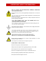
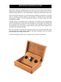
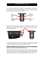
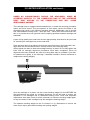
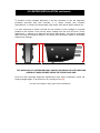
!
IO LIMITED
!
!
MOVING COIL CARTRIDGE AND
POWER SUPPLY
OWNERʼS INFORMATION
!
CONTENTS
!
1)
IMPORTANT SAFETY INFORMATION
2)
CE DECLARATION OF CONFORMITY
DISPOSAL
POWER REQUIREMENTS
3)
INTRODUCTION
4)
OVERVIEW
UNPACKING AND INSTALLATION
5) VALVE INSTALLATION
6)
CONNECTION
7)
OPERATION
8)
TECHNICAL SPECIFICATIONS
9)
WARRANTY INFORMATION
10)
CONTACT INFORMATION
! IMPORTANT SAFETY INFORMATION !
RISK OF SHOCK OR ELECTROCUTION! INTERNAL OPERATING
VOLTAGES ARE LETHAL!
Do not remove top cover, unless specifically instructed to do so in the user
manual.
This unit contains fuses and other safety components in accordance with
BS60065 requirements.
In the event of failure, replacement fuse or safety component must be of
the same part type and value.
!
SUCH REPLACEMENT MUST ONLY BE CARRIED OUT BY A
QUALIFIED SERVICE TECHNICIAN.
Do not attempt to replace any fuses without first disconnecting the unit
from the mains electricity supply.
This product must be earthed – ensure that the mains supply cable earth /
ground is correctly connected.
!
This product generates high levels of heat. Adequate ventilation must
be provided. Do not restrict airflow through any ventilation slots or
place the unit on any surface that may restrict airflow.
Valve equipment operates at extremely high temperatures;
KEEP OUT OF THE REACH OF CHILDREN AND ANIMALS.!
Do not store or operate this unit in areas of high humidity or in close
proximity to water / moisture.
Do not expose or immerse the unit in liquid of any kind.
!
OTHER
SAFETY PRECAUTIONS: Never touch the power cord with wet hands.
Always remove the power cord by grasping the plug, not the cable.
Never expose the unit to excessive heat or magnetism.
Never let an inexperienced person repair or reassemble the unit.
Never put anything, especially metal objects, inside the unit.
Never place excessive weight on the unit.
!
CE DECLARATION OF CONFORMITY
We declare under our sole responsibility that this product is in conformity
with the following standards or standardized documents:
BS EN 60065 in accordance with the regulations 73/23/EEC, 89/336/EEC
(from 1 January 1997)
CE 94
Peter Qvortrup,
Director
Audio Note (UK) Limited
25 Montefiore Road
Hove
East Sussex
BN3 1RD
United Kingdom
Tel:
Fax:
+44 (0)1273 220 511
+44 (0)1273 731 498
!
DISPOSAL
This product must not be disposed of as normal household waste. To
prevent possible harm to the environment please separate the product
from other waste to ensure that it can be recycled in an environmentally
safe manner. Please contact your retailer or the appropriate local
government office for collection facilities.
!
POWER REQUIREMENTS
Power requirements for electrical equipment vary depending on your geographical
location. Please ensure that your unit meets the power requirements in your area.
The power requirement for your unit is marked on the serial number plate, located on
the rear panel.
If you are in doubt, please contact your dealer before plugging the unit into the mains
supply.
INTRODUCTION
Thank you for purchasing this Audio Note (UK) product. With the correct care it
should give you many years of pleasure and enjoyment.
Please take the time to read all of the information in this manual before connecting
your new component to an electrical supply or your system, to ensure both your
safety and satisfaction.
Please note that due to our desire to continually improve products, specifications are
subject to change without notice. Therefore it is important to refer to the manual that
is supplied with your product for the most accurate information; manuals downloaded
from our website or obtained from other sources may no longer fully apply to your
product.
If you have any questions regarding the information contained within this document
or your new component, please feel free to contact us: -
Audio Note (UK) Limited
25 Montefiore Road
Hove
East Sussex
BN3 1RD
United Kingdom
Tel:
+44 (0)1273 220 511
Fax:
+44 (0)1273 731 498
e-mail: [email protected]
IO LIMITED MOVING COIL CARTRIDGE
Congratulations on your purchase of the Audio Note (UK) IO Limited Moving Coil
cartridge. It is, without question, the finest and most technically significant Moving
Coil cartridge available today. No other cartridge offers such an unparalleled
combination of hitherto unknown performance, information retrieval, dynamic
contrast, tonal accuracy and sheer musical enjoyment.
Generator Principle
The moving coil principle was chosen as the basis for the design of the IO range of
cartridges, as it offers greater linearity in terms of electrical output from the
mechanical movements of the stylus than any other system. We investigated moving
iron, moving magnet, strain gauge, electret and electrostatic generators, and even
took the unusual step of acquiring a Toshiba cartridge that employed light emitting
diodes to generate the signal from the groove, but in the end it was felt that the
quality of the moving coil system as described by P. G. A. H. Voigt would yield the
best overall results.
Mechanical Construction
To ensure that the stored information on the disc is precisely recovered, it is essential
that the mechanical movement of the stylus is accurately translated into an electrical
signal. Any extraneous excitations arising as a result of vibrations in the cartridge
housing must be eliminated.
Therefore in the design of the Audio Note (UK) cartridges considerable attention has
been paid to the rigidity and structural integrity of the body, and to ensuring that the
adopted mechanical construction stores the absolute minimum of resonant energy,
which will degrade the signal derived from the disc being played.
Mechanical integrity of the cartridge body is an aspect of design that has never been
adequately dealt with before, and as a result all other cartridges suffer greatly from
colourations derived from internal resonances and/or energy stored in their body
assemblies.
To achieve the incredible level of mechanical integrity required for the IO cartridges,
all aspects of body design were reexamined, to minimize standing waves and
eliminate any resonating air pockets within the assembly.
The benefits of getting the mechanical assembly right would be lost if the complete
assembly could not be rigidly mounted in the tonearm, hence the incorporation of the
largest possible surface mounting area and the provision of up to six (6!) bolts to
secure the cartridge to the head shell.
IO LIMITED MOVING COIL CARTRIDGE
Magnetic circuit
Once the mechanical assembly had been perfected the next area to which particular
attention was paid was the magnetic circuit.
From numerous tests carried out on a variety of materials and configurations, it was
established that different types of magnetic materials exert a subtle influence on the
perceived quality of the final sound.
After further extensive research the optimal magnetic circuit was found to be electro
magnetically generated. This, however, requires a separate DC power supply and is
very costly to implement. Therefore, only a cartridge producing the absolute ultimate
in performance could employ such a system… and the IO Limited was born.
Wire Material
Because of the low impedance and very low output of the IO Limited, it is essential
that the minimum number of electrical connections occur along the wire and that the
wire itself is of the highest possible quality. Not surprisingly we chose our custom
made Audio Note (UK) 99.99% pure silver wire, and the coil wire extends all the way
to the output terminals, avoiding all unnecessary connections.
Cantilever, Material and Design
It is on the design and construction of the cantilever that much of the quality of a
cartridge depends. Many materials were investigated, Boron, Beryllium, Sapphire,
Diamond and Titanium and all except Titanium were disregarded in the final analysis,
due to deficiencies in one or more areas.
It is vitally important for the cantilever and stylus assembly to be as rigid as possible
in order to accurately transfer the stylus motion to the coil assembly, without adding
any unwanted vibration as a result of flexing or bending.
The optimum cantilever material here was found to be an extra thick walled, slightly
tapered Titanium tube, the taper being both outside AND inside, since this affords by
far the greatest rigidity.
Another advantage provided by this type of material was the possibility of employing
a longer cantilever, which greatly reduces cantilever excursions. This has three main
benefits: 1) It is easier for the stylus to track complex, highly modulated grooves.
2) The resultant smaller coil movement reduces the nonlinearities in the magnetic
field, so the field will ʻbendʼ less.
3) Damping can be reduced, as it becomes easier to control stylus movement.
IO LIMITED MOVING COIL CARTRIDGE
Damping
As mentioned above, damping of the cantilever is extremely critical. Too much and
the cartridge will sound dull, as a large amount of the critical energy from the record
will be absorbed in the damper instead of reaching the coils, reducing the efficiency
of the energy transfer from the record (as vibrational energy) to the cartridge (as
electrical energy).
Conversely, too little damping will make the cantilever prone to uncontrolled
excursions, resulting in unwanted distortions and poor tracking.
Much experimentation led to a precision Butyl rubber damper, offering a wide
operating temperature range and minimal hysteresis effects. The tension on the
damper is furthermore adjustable, allowing very accurate set-up of each cartridgeʼs
individual suspension.
Stylus Choice
Finally the assembly is completed with the use of a solid diamond stylus. A heroic
degree of effort has been expended finding the best possible solution to this, the
most critical interface with the “plastic”. Having been ultimately unsatisfied with the
offerings from the various stylus manufacturers around the globe, in 1995 we
contracted a company to develop a process which would allow them to cut and polish
a perfect, natural octagon to a level of the best surgical instruments used for eye and
other fine surgery, on a diamond less than half the size of the closest, readily
available option at that time. This remains to the best of our knowledge the finest
diamond in use on any cartridge available today.
The improvements over any standard diamonds use in other cartridges can be briefly
described as better tracking of high frequencies, lower surface noise, lower record
wear, longer stylus life, smaller tip mass and lower tracking force.
The stylus is first ʻpinchedʼ into place by the cantilever and then glued, using a single
component epoxy resin, which needs ʻbakingʼ for about three hours to harden.
Test Procedure
After assembly, each cartridge is subjected to a series of tests, one of which involves
a fast dynamic frequency sweep, at high amplitude; this method shows up any
undesirable problems in the cartridge. Special test equipment and test records had to
be developed for this process, which is exclusive to Audio Note (UK).
UNPACKING AND INSTALLATION
Please take care when unpacking your IO Limited. Choose a clean, clear location to
unpack your cartridge. We recommend that you retain and carefully store all of the
original packing materials, in case transportation / shipping is required at a later date.
Open the wooden transit box. You will see that the cartridge is mounted on a wooden
insert for protection during shipping. The cartridge is supplied with the removable
stylus guard installed, and we recommend leaving it in place during the initial
installation procedure.
Carefully remove the wooden insert. Underneath, you should find an appropriately
sized hex head wrench. Gently hold the cartridge by its side cheeks, and identify the
two mounting bolts that secure it to the wooden insert. Carefully remove the two
mounting bolts, and once removed, retain these as they can be used to attach the IO
Limited to your tonearm heashell.
Once the cartridge, mounting bolts and wrench have been removed, place the transit
box and insert to one side. Once installation has been completed, return the wrench
to the box and store safely for later use.
You are now ready to mount your IO Limited in your tonearmʼs head-shell.
IO LIMITED INSTALLATION
It is often easier to connect the tonearm wires to the connection pins located at the
rear of the cartridge body before it is mounted in the head-shell. The pins are colour
coded according to the International Standard Colour Code. Connect the four
tonearm wires to the corresponding cartridge pins: -
RIGHT
POSITIVE
ʻREDʼ
RIGHT
NEGATIVE
ʻGREENʼ
LEFT
POSITIVE
ʻWHITEʼ
LEFT
NEGATIVE
ʻBLUEʼ
As the IO Ltd is a field coil design, it requires a DC voltage to generate the internal
magnetic field. To receive this voltage from the external power supply unit, the
cartridge is equipped with an additional pair of connection pins, located at the top /
rear of the cartridge body: -
To connect these pins to the external power supply unit, an additional pair of internal
(or external) arm wires and a two core / twisted pair external arm cable of suitable
length (to reach the external power supply unit) will be required.
PLEASE REMEMBER THAT THE POWER SUPPLY UNIT CONNECTION CABLES
MUST BE OF SUITABLE SIZE AND FLEXIBILITY SO THAT THE TRACKING AND
OPERATION OF THE TONEARM IS NOT DISRUPTED.
Audio Note (UK) manufacture dedicated versions of their tonearms for the IO Limited,
equipped with 6 internal wires and an additional length of external cable from the
base of the tonearm. For further information regarding these models, please contact
your Audio Note (UK) Dealer, or alternatively please feel free to contact us direct.
IO LIMITED INSTALLATION continued…
UNDER NO CIRCUMSTANCES SHOULD THE HEAD-SHELL WIRES BE
SOLDERED DIRECTLY TO THE CONNECTION PINS OF THE CARTRIDGE
BODY. HEAT APPLIED TO THE CONNECTION PINS WILL CAUSE
IRREPARABLE DAMAGE.
The cartridge body is equipped with threaded holes, to make the mounting procedure
easier and more secure. They are spaced 12.7mm apart, (across the width of the
cartridge body) which is the industry standard distance. Additionally, the IO Limited
has six threaded mounting holes – three per side – rather than the conventional two;
this is to provide the most rigid and secure coupling possible between cartridge and
headshell.
A pair of high quality hex head bolts and an appropriately sized wrench are provided
for mounting the cartridge body to the head-shell.
Pass the bolts down (from above) through the mounting holes in the head-shell, and
align them with the threaded holes in the top surface of the cartridge body.
Gently tighten the bolts to hold the cartridge securely in place. Do not fully tighten the
bolts until all cartridge alignment procedures have been completed. (Once all
alignment has been finalized, the extra four fixing bolts may be installed if you wish,
to maximize the rigidity of the cartridge / headshell interface. Please remember to
readjust the tracking weight!).
Once the cartridge is in place, set the correct tracking weight. Do this BEFORE the
final adjustments are made for cartridge alignment, as this will help to ensure the
cantilever is not damaged due to excessive tracking force. Once final alignment
adjustments have been made, it will be necessary to check the tracking weight again,
as any movement of the cartridge body will change the tracking weight.
The optimum tracking weight for the IO Limited is 2.5g. Remember to remove the
clear acrylic stylus guard before setting the tracking weight!
IO LIMITED INSTALLATION continued…
To achieve correct cartridge alignment, it will be necessary to use the alignment
protractor provided with your tonearm. If in doubt, contact your tonearm
manufacturer, or contact you Audio Note (UK) dealer, who will be able to advise you.
It is also important to make sure that the top surface of the cartridge is mounted
parallel to the surface of the record, when viewed from the front and side. These
adjustments – referred to as Azimuth and Stylus Rake Angle – will have a noticeable
effect on tonal and channel balance, and every effort should be made to accurately
adjust these settings.
TOP SURFACE OF CARTRIDGE BODY SHOULD BE PARALLEL WITH RECORD
SURFACE, WHEN VIEWED FROM THE FRONT AND SIDE.
Once the final cartridge alignment adjustments have been completed, check the
tracking weight again, to ensure that it is correctly set at 2.5g.
You are now ready to enjoy your record collection!
IO LIMITED PSU INITIAL SET UP
WE STRONGLY RECOMMEND THE INITIAL IO LIMITED POWER SUPPLY
INSTALLATION AND SET UP SHOULD BE CARRIED OUT BY AN APPOINTED
AUDIO NOTE (UK) DEALER.
IRREPARABLE DAMAGE NOT COVERED UNDER WARRANTY MAY BE
CAUSED TO THE CARTRIDGE AND POWER SUPPLY BY INCORRECT INITIAL
SET UP.
Once all cartridge connections have been made, the operating voltage for the
cartridge can be set.
ENSURE THE ʻCARTRIDGEʼ SWITCH IS IN THE ʻOFFʼ POSITION
(TURNED ANTICLOCKWISE / LEFT).
Connect the power supply unit to the mains supply, via the IEC socket located on the
rear / right of the device. Once connected, turn the unit on using the ʻMains Onʼ
switch, located on the right hand side of the front fascia. Turn the switch clockwise /
right. The red ʻpowerʼ LED situated below the ʻMains Onʼ switch should glow RED.
Next, switch on the meter using the ʻMeterʼ switch, located on the lower left hand side
of the front fascia. Turn the switch clockwise / right.
At this stage the meter on the front of the power supply unit should show a reading of
1.8V DC – 2.0V DC (divide the value on the meter scale by 10).
Turn the cartridge supply on using the ʻCartridge Onʼ switch, located on the left hand
side of the front fascia. Turn the switch clockwise / right.
With an accurate voltmeter set to the 2V DC scale, measure the voltage at the PSU
connection pins on the cartridge.
BE EXTREMELY CARFUL, AND DO TOUCH BOTH PINS WITH THE SAME TEST
PROBE OR CREATE A SHORT CIRCUIT; THIS WILL POSSIBLY DAMAGE THE
CARTRIDGE AND POWER SUPPLY!!
The voltage at the PSU connection pins on the cartridge should be in the region of
1.2V DC to 1.3V DC.
If the voltage is within the required region, proceed to the next section of this manual
entitled ʻOPERATIONʼ. If it is higher or lower than required, the voltage must be
adjusted as follows: On the rear of the power supply unit is the cartridge voltage potentiometer. Viewed
from the rear of the PSU, turn this switch ANTICLOCKWISE to INCREASE cartridge
voltage and CLOCKWISE to DECREASE cartridge voltage.
Check the cartridge voltage again, and repeat the above steps until a voltage of
between 1.2V DC and 1.3V DC is achieved.
NEVER SET THE CARTRIDGE VOLTAGE TO GREATER THAN 1.3V DC!
OPERATION
Once the initial power supply unit set up has been completed and the IO Limited has
been correctly installed in your tonearm, you are ready to begin operation.
Mains On
This switch is used to turn the Power Supply Unit on, and is
located on the right hand side of the front fascia. Turn the
switch clockwise / right. The red ʻpowerʼ LED situated below
the ʻMains Onʼ switch should glow RED.
THE POWER SUPPLY UNIT SHOULD BE SWITCHED OFF
WHEN NOT IN USE FOR AN EXTENDED PERIOD (MORE
THAN A FEW DAYS).
Cartridge On
This switch is used to apply the required voltage to the
cartridge. When you wish to use the Io Limited (to play music!),
turn the switch clockwise / right. There are two reasons for this
switch; firstly, it allows the power supply unit to remain
polarized even when the cartridge is not in use (Cartridge On
switch in the ʻOFFʼ / anticlockwise position), and secondly, it
allows the supply to be disconnected when not in use, which
prolongs the life of the Io Limited.
THE CARTRIDGE SHOULD ALWAYS BE SWITCHED OFF
WHEN NOT IN USE!
Meter On
Located on the lower left hand side of the front fascia, this
switch is used to activate the test meter, positioned on the front
of the power supply unit. Turn the switch clockwise / right.
Meter
The meter allows the user to monitor the approximate voltage
being supplied to the cartridge. With the cartridge turned on
(see Cartridge On above) and the meter turned on
(see Meter On above) the meter should read approximately
1.2 V DC to 1.4 V DC. With the cartridge turned off, the meter
will show a higher reading.
IF THE METER SHOWS A READING GREATER THAN 1.2V
DC TO 1.4V DC WHEN THE CARTRIDGE IS SWITCHED ON,
SWITCH THE POWER SUPPLY UNIT OFF IMMEDIATELY
AND CONTACT YOUR AUTHORIZED AUDIO NOTE (UK)
DEALER.
OPERATION Continued…
Cleaning
No special maintenance is required for the power supply unit.
Use a soft, clean lint free cloth to remove any surface marks
from the casework. For finger marks / grease, use a soft, clean
lint free cloth, lightly moistened with a solution of warm water
and mild detergent. Do not use any alcohol or solvent based
cleaning products, as they may damage the finish of the
amplifier.
ENSURE THAT THE POWER SUPPLY UNIT IS SWITCHED
OFF
AND
DISCONNECTED
FROM
THE
MAINS
ELECTRICITY SUPPLY BEFORE UNDERTAKING ANY
CLEANING.
The IO Limited requires no special maintenance or cleaning.
Under no circumstances should any liquid or solvent-based
cleaning solutions be applied to the diamond or cantilever.
Build up of dust of fluff can be gently blown away, and only in
very extreme circumstances should a small, soft artistʼs brush
be used to clean the diamond of cantilever, moving the brush,
slowly, gently and extremely carefully from back to front, never
in the opposite direction or from side to side.
Cartridge Life
The operational life of a cartridge can be affected by a variety
of factors, such as frequency of use, ambient temperature,
humidity, quality of vinyl being played etc. Our approximate
estimates for the lifespan of the IO Limited is within the region
of 1000 to 3000 hours, depending on and not limited to the
factors mentioned above.
Rebuilding
We offer a very affordable rebuilding service for all Audio Note
IO cartridges, should they become damaged or if they have
reached the end of their operational life. If you wish to have
your IO Limited rebuilt or retipped, please contact us directly: -
Audio Note (UK) Limited
25 Montefiore Road
Hove
East Sussex
BN3 1RD
United Kingdom
Tel:
+44 (0)1273 220 511
Fax:
+44 (0)1273 731 498
e-mail: [email protected]
TECHNICAL SPECIFICATIONS
OUTPUT VOLTAGE
0.04mV / 5cm / sec
INTERNAL IMPEDANCE
1 Ohm
MATCHING IMPEDANCE
3 – 4 Ohms
FREQUENCY RANGE
10 – 50KHz, +/- 2dB (dynamic test)
SEPARATION
Greater than 30dB at 1KHz
COMPLIANCE (TYPICAL)
Horizontal 10
Vertical 15
MAGNETIC FIELD STRENGTH
Electromagnetic 1,200 Gauss
WEIGHT
19g
STYLUS PRESSURE
1.5 – 4g
2.5g optimal
POWER SUPPLY OUTPUT VOLTAGE
0.4A, 1.2V DC
POWER SUPPLY WEIGHT AND
DIMENSIONS
300mm(w) x 250mm(d) x 100mm(h)
Weight 5Kg
NOTE
Due to Audio Note (UK)ʼs ongoing research and
development program, specifications are subject
to change without notice.
WARRANTY INFORMATION
Audio Note (UK) warrants this product to be free from defects in materials and
workmanship for two years from the original date of purchase from an appointed
Audio Note (UK) dealer, and agrees to cover the cost of parts and associated labour
required to correct such defects, subject to terms & conditions.
This Warranty is offered to the first purchaser only.
Any valves supplied with the unit are warranted for three months from the original
date of purchase.
If the product fails in normal domestic use and during the Warranty period due to the
above described faults or defects, Audio Note (UK) will, at its discretion, repair or
replace the item free of charge within a reasonable time once it has been returned to
Audio Note (UK) or an appointed Audio Note (UK) dealer or service engineer.
Audio Note (UK) is not liable for any shipping charges incurred whilst transporting the
product to or from Audio Note (UK) or an appointed Audio Note (UK) dealer or
service engineer, should the item require service or repair during or after the
Warranty period.
If the product must be shipped, please use the original packaging materials and
include a copy of the original sales receipt along with a note explaining, in as much
detail as possible, the problems you are experiencing with the unit.
Only use a reputable Courier Service or Shipping Agent, and ensure that your
product is insured during transit.
Any servicing, repairs or modifications not authorized by Audio Note (UK), or
carried out by persons other than appointed Audio Note (UK) service
engineers will invalidate any warranty.
This Warranty does NOT cover: Damage sustained whilst in the possession of a shipping agent, retailer or consumer
and not caused as a direct result of defects in materials or workmanship.
Damage caused by normal wear and tear.
Damage or defects caused by abnormal or unreasonable use.
Damage caused by accident, acts of nature, misuse or neglect.
Damage caused by a failure to follow the operating and installation instructions
supplied with the product.
Damage caused by improper or careless cleaning.
Audio Note (UK) reserves the right to refuse warranty for any component of which
the serial number has been removed, defaced or tampered with.
CONTACT INFORMATION
If in the future your Audio Note (UK) product
requires servicing, or if you require technical support
or have any questions regarding this or any of our
other products, please contact your local Audio Note
(UK) dealer.
Alternatively, please feel free to contact us directly: -!
Audio Note (UK) Limited
25 Montefiore Road
Hove
East Sussex
BN3 1RD
United Kingdom
Tel:
+44 (0)1273 220 511
Fax:
+44 (0)1273 731 498
e-mail: [email protected]