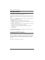
1
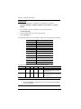
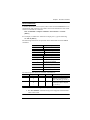
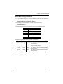
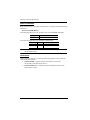
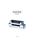
4/8-Port HDMI over single Cat 5 Splitter VS1814T / VS1818T User Manual www.aten.com VS1814T / VS1818T User Manual FCC Information FEDERAL COMMUNICATIONS COMMISSION INTERFERENCE STATEMENT This equipment has been tested and found to comply with the limits for a Class A digital device, pursuant to Part 15 of the FCC Rules. These limits are designed to provide reasonable protection against harmful interference when the equipment is operated in a commercial environment. This equipment generates, uses, and can radiate radio frequency energy and, if not installed and used in accordance with the instruction manual, may cause harmful interference to radio communications. Operation of this equipment in a residential area is likely to cause harmful interference in which case the user will be required to correct the interference at his own expense. FCC Caution: Any changes or modifications not expressly approved by the party responsible for compliance could void the user's authority to operate this equipment. CE Warning: This is a class A product. In a domestic environment this product may cause radio interference in which case the user may be required to take adequate measures. RoHS This product is RoHS compliant. SJ/T 11364-2006 The following contains information that relates to China. ii VS1814T / VS1818T User Manual User Information Online Registration Be sure to register your product at our online support center: International http://eservice.aten.com Telephone Support For telephone support, call this number: International 886-2-8692-6959 China 86-10-5255-0110 Japan 81-3-5615-5811 Korea 82-2-467-6789 North America 1-888-999-ATEN ext 4988 United Kingdom 44-8-4481-58923 User Notice All information, documentation, and specifications contained in this manual are subject to change without prior notification by the manufacturer. The manufacturer makes no representations or warranties, either expressed or implied, with respect to the contents hereof and specifically disclaims any warranties as to merchantability or fitness for any particular purpose. Any of the manufacturer's software described in this manual is sold or licensed as is. Should the programs prove defective following their purchase, the buyer (and not the manufacturer, its distributor, or its dealer), assumes the entire cost of all necessary servicing, repair and any incidental or consequential damages resulting from any defect in the software. The manufacturer of this system is not responsible for any radio and/or TV interference caused by unauthorized modifications to this device. It is the responsibility of the user to correct such interference. The manufacturer is not responsible for any damage incurred in the operation of this system if the correct operational voltage setting was not selected prior to operation. PLEASE VERIFY THAT THE VOLTAGE SETTING IS CORRECT BEFORE USE. iii VS1814T / VS1818T User Manual Package Contents The VS1814T / VS1818T 4/8-Port HDMI over single Cat 5 Splitter package consists of: 1 VS1814T / VS1818T 4/8-Port HDMI over single Cat 5 Splitter 1 Power Cord 1 Mounting Kit 1 User Instructions* Check to make sure that all the components are present and that nothing got damaged in shipping. If you encounter a problem, contact your dealer. Read this manual thoroughly and follow the installation and operation procedures carefully to prevent any damage to the unit, and/or any of the devices connected to it. * Features may have been added to the VS1814T / VS1818T since this manual was printed. Please visit our website to download the most up-to-date version. © Copyright 2014 ATEN® International Co., Ltd. Manual Date: 2014-10-16 ATEN and the ATEN logo are registered trademarks of ATEN International Co., Ltd. All rights reserved. All other brand names and trademarks are the registered property of their respective owners. iv VS1814T / VS1818T User Manual Contents FCC Information . . . . . . . . . . . . . . . . . . . . . . . . . . . . . . . . . . . . . . . . . . . . . ii RoHS. . . . . . . . . . . . . . . . . . . . . . . . . . . . . . . . . . . . . . . . . . . . . . . . . . . . . . ii SJ/T 11364-2006. . . . . . . . . . . . . . . . . . . . . . . . . . . . . . . . . . . . . . . . . . . . . ii User Information . . . . . . . . . . . . . . . . . . . . . . . . . . . . . . . . . . . . . . . . . . . . .iii Online Registration . . . . . . . . . . . . . . . . . . . . . . . . . . . . . . . . . . . . . . . .iii Telephone Support . . . . . . . . . . . . . . . . . . . . . . . . . . . . . . . . . . . . . . . .iii User Notice . . . . . . . . . . . . . . . . . . . . . . . . . . . . . . . . . . . . . . . . . . . . . .iii Package Contents. . . . . . . . . . . . . . . . . . . . . . . . . . . . . . . . . . . . . . . . . . . iv Contents . . . . . . . . . . . . . . . . . . . . . . . . . . . . . . . . . . . . . . . . . . . . . . . . . . . v About this Manual . . . . . . . . . . . . . . . . . . . . . . . . . . . . . . . . . . . . . . . . . . . vii Conventions . . . . . . . . . . . . . . . . . . . . . . . . . . . . . . . . . . . . . . . . . . . . . . .viii Product Information. . . . . . . . . . . . . . . . . . . . . . . . . . . . . . . . . . . . . . . . . .viii 1. Introduction Overview . . . . . . . . . . . . . . . . . . . . . . . . . . . . . . . . . . . . . . . . . . . . . . . . . . . 1 Features . . . . . . . . . . . . . . . . . . . . . . . . . . . . . . . . . . . . . . . . . . . . . . . . . . . 2 Requirements . . . . . . . . . . . . . . . . . . . . . . . . . . . . . . . . . . . . . . . . . . . . . . . 3 Source Device . . . . . . . . . . . . . . . . . . . . . . . . . . . . . . . . . . . . . . . . . . . . 3 Receiving Device. . . . . . . . . . . . . . . . . . . . . . . . . . . . . . . . . . . . . . . . . . 3 Cables . . . . . . . . . . . . . . . . . . . . . . . . . . . . . . . . . . . . . . . . . . . . . . . . . . 3 Components . . . . . . . . . . . . . . . . . . . . . . . . . . . . . . . . . . . . . . . . . . . . . . . . 4 Front View . . . . . . . . . . . . . . . . . . . . . . . . . . . . . . . . . . . . . . . . . . . . . . 4 Rear View . . . . . . . . . . . . . . . . . . . . . . . . . . . . . . . . . . . . . . . . . . . . . . . 5 2. Hardware Setup Rack Mounting . . . . . . . . . . . . . . . . . . . . . . . . . . . . . . . . . . . . . . . . . . . . . . 7 Grounding . . . . . . . . . . . . . . . . . . . . . . . . . . . . . . . . . . . . . . . . . . . . . . . . . . 9 Installation . . . . . . . . . . . . . . . . . . . . . . . . . . . . . . . . . . . . . . . . . . . . . . . . . 10 3. Operation Overview . . . . . . . . . . . . . . . . . . . . . . . . . . . . . . . . . . . . . . . . . . . . . . . . . . 11 EDID Learn Pushbutton . . . . . . . . . . . . . . . . . . . . . . . . . . . . . . . . . . . . . . 11 EDID Mode Selection . . . . . . . . . . . . . . . . . . . . . . . . . . . . . . . . . . . . . . . . 12 Installing the RS-232 Controller . . . . . . . . . . . . . . . . . . . . . . . . . . . . . . . . 12 4. RS-232 Commands Overview . . . . . . . . . . . . . . . . . . . . . . . . . . . . . . . . . . . . . . . . . . . . . . . . . . 13 RS-232 Serial Interface. . . . . . . . . . . . . . . . . . . . . . . . . . . . . . . . . . . . . . . 13 Configuring the Serial Port . . . . . . . . . . . . . . . . . . . . . . . . . . . . . . . . . 13 Switch Port . . . . . . . . . . . . . . . . . . . . . . . . . . . . . . . . . . . . . . . . . . . . . 14 CEC Commands . . . . . . . . . . . . . . . . . . . . . . . . . . . . . . . . . . . . . . . . . 15 Read Commands . . . . . . . . . . . . . . . . . . . . . . . . . . . . . . . . . . . . . . . . 16 Baud Rate Setting Commands . . . . . . . . . . . . . . . . . . . . . . . . . . . . . . 17 Reset Commands . . . . . . . . . . . . . . . . . . . . . . . . . . . . . . . . . . . . . . . . 18 Verification. . . . . . . . . . . . . . . . . . . . . . . . . . . . . . . . . . . . . . . . . . . . . . 18 v VS1814T / VS1818T User Manual Appendix Safety Instructions . . . . . . . . . . . . . . . . . . . . . . . . . . . . . . . . . . . . . . . . . . 19 General . . . . . . . . . . . . . . . . . . . . . . . . . . . . . . . . . . . . . . . . . . . . . . . . 19 Rack Mounting . . . . . . . . . . . . . . . . . . . . . . . . . . . . . . . . . . . . . . . . . . 21 Technical Support. . . . . . . . . . . . . . . . . . . . . . . . . . . . . . . . . . . . . . . . . . . 22 International . . . . . . . . . . . . . . . . . . . . . . . . . . . . . . . . . . . . . . . . . . . . 22 North America . . . . . . . . . . . . . . . . . . . . . . . . . . . . . . . . . . . . . . . . . . . 22 Specifications . . . . . . . . . . . . . . . . . . . . . . . . . . . . . . . . . . . . . . . . . . . . . . 23 Limited Warranty. . . . . . . . . . . . . . . . . . . . . . . . . . . . . . . . . . . . . . . . . . . . 24 vi VS1814T / VS1818T User Manual About this Manual This User Manual is provided to help you get the most from your VS1814T / VS1818T system. It covers all aspects of installation, configuration and operation. An overview of the information found in the manual is provided below. Introduction, introduces you to the VS1814T / VS1818T system. Its purpose, features and benefits are presented, and its front and back panel components are described. Hardware Setup, describes how to set up your VS1814T / VS1818T installation. The necessary steps are provided. Operation, explains the fundamental concepts involved in operating the VS1814T / VS1818T through the RS-232 serial interface. An Appendix, provides specifications and other technical information regarding the VS1814T / VS1818T. vii VS1814T / VS1818T User Manual Conventions This manual uses the following conventions: Monospaced Indicates text that you should key in. [] Indicates keys you should press. For example, [Enter] means to press the Enter key. If keys need to be chorded, they appear together in the same bracket with a plus sign between them: [Ctrl+Alt]. 1. Numbered lists represent procedures with sequential steps. ♦ Bullet lists provide information, but do not involve sequential steps. → Indicates selecting the option (on a menu or dialog box, for example), that comes next. For example, Start → Run means to open the Start menu, and then select Run. Indicates critical information. Product Information For information about all ATEN products and how they can help you connect without limits, visit ATEN on the Web or contact an ATEN Authorized Reseller. Visit ATEN on the Web for a list of locations and telephone numbers: International http://www.aten.com North America http://www.aten-usa.com viii Chapter 1 Introduction Overview The ATEN VS1814T / VS1818T 4/8-Port HDMI over single Cat 5 Splitter is a fast and efficient way of switching digital high definition video from one input source to 4/8 displays located up to 100m away. It implements HDBaseT extension technology to connect the VS1814T / VS1818T to receiver units over one single Cat 5e cable in order to transmit rich HDMI multimedia content in real time. You can connect up to 4 (VS1814T) or 8 (VS1818T) HDMI Receivers (such as VE812R) to a unit. The built-in RS-232 port on the VS1814T / VS1818T rear panel allows connected units to be controlled through a high-end controller or PC. The VS1814T / VS1818T supports up to 4k2k HDTV resolution, as well as up to 1920 x 1200 PC resolution. It is equipped with an EDID selection method, providing constant and reliable EDID data for the HDMI source device to efficiently optimize video resolution. The VS1814T / VS1818T HDMI Splitter is HDCP (High Bandwidth Digital Content Protection) compliant and compatible with a wide range of ATEN devices (switches, matrix, converters, and so on). It supports all HDMIenabled equipment, such as DVD players, satellite set-top boxes and all HDMI displays, making it an effective solution in broadcasting applications, digital signage and educational settings. 1 VS1814T / VS1818T User Manual Features One HDMI input to 4/8 HDMI outputs via a Cat 5e cable Offers local HDMI output Extends displays up to 100 m Anti-jamming – resists signal interference during high-quality video transmissions using HDBaseT technology Implements HDBaseT extension technology using only one Cat 5 cable to connect the transmitter and receiver HDMI (3D, Deep color, 4kx2k); HDCP Compatible Supports Dolby True HD and DTS HD Master Audio Consumer Electronics Control (CEC) support Built-in bi-directional RS-232 serial remote port for high-end system control* Supports resolutions of up to Ultra HD 4kx2k and 1080p Full HD Supports up to 340MHz bandwidth for high performance video Signaling rates up to 3.4 Gbits EDID mode selection Rack-mountable * The VS1814T / VS1818T AP operation instructions can be downloaded from the ATEN website (www.aten.com). 2 Chapter 1. Introduction Requirements The following equipment is required for a complete VS1814T / VS1818T installation: Source Device The following equipment must be installed on any source of HDMI content: HDMI output connector Receiving Device A local display device with an HDMI input connector An HDMI Receiver (such as VE812R) with an RJ-45 port for each output port you will be installing Cables Standard HDMI cables for the source device and local display device Cat 5e cables for the HDMI Receivers Note: 1. No cables are included in this package. We strongly recommend that you purchase high-quality cables of appropriate lengths since this will affect the quality of the audio and video display. Contact your dealer to purchase the correct cable sets. 2. A DVI/HDMI adapter is required when connecting to a DVI source or display device. If a DVI/HDMI adapter is used. audio is not supported. 3. If you wish to utilize the VS1814T / VS1818T’s high-end serial controller function, you will also need to purchase an appropriate RS232 cable. See Installing the RS-232 Controller, page 12. 3 VS1814T / VS1818T User Manual Components Front View 1 No. 2 3 4 5 6 Component Description 1 HDBaseT Out port LEDs (1~4 / 1~8) Lights to indicate there is a working connection to the HDMI receiving device(s) connected to the port(s). 2 HDMI Out LED Lights to indicate there is a working connection to the local display device. 3 HDMI In LED Lights to indicate that there is a working connection to the source device (i.e., computer). 4 EDID Learn Pushbutton Press and release this button to automatically learn the active display’s EDID. 5 EDID Learn LED Flashes green to indicate that EDID Learning Mode is in progress (see EDID Learn Pushbutton, page 11). Lights green to indicate that EDID learning process is successful. Lights red to indicate that EDID learning process failed. 6 Power LED Lights green to indicate that the VS1814T / VS1818T is receiving power and is up and running. Note: The VS1818T’s front panel is shown on this page. It is similar to the front panel of VS1814T except for the number of HDBaseT Out port LEDs – the VS1814T has 4 HDBaseT Out port LEDs. 4 Chapter 1. Introduction Rear View 1 No. 2 3 4 Component 6 5 7 8 9 Function 1 Power Socket This is a standard 3-pin AC power socket. The power cord from an AC source plugs in here. 2 Power Switch This is a standard rocker switch that powers the unit on and off. 3 Grounding Terminal The grounding wire attaches here. See Grounding, page 9, for further details. 4 EDID Mode Switch Press this button to cycle through the EDID settings stored in the unit (see EDID Mode Selection, page 12). 5 HDBaseT Out ports The Cat 5e cables that connects the HDMI Receiver Units plug in here. (1~4 / 1~8) 6 HDMI Input port The cable from your HDMI source device plugs in here. 7 HDMI Output port The cable from your HDMI display device plugs in here. 8 Firmware Upgrade button This button is for enabling the Firmware Upgrade Mode. Note: Contact your product provider for details on upgrading the firmware of your device. 7 RS-232 Serial Port This is the serial remote port for output source selection and high-end system control, including firmware upgrade. Note: The VS1818T’s rear panel is shown on this page. It is similar to the rear panel of VS1814T except for the number of HDBaseT Out ports – the VS1814T has 4 HDBaseT Out ports. 5 VS1814T / VS1818T User Manual This Page Intentionally Left Blank 6 Chapter 2 Hardware Setup 1. Important safety information regarding the placement of this device is provided on page 19. Please review it before proceeding. 2. Make sure that the power to all devices connected to the installation are turned off. 3. Make sure that all devices you will be installing are properly grounded. Rack Mounting For convenience and flexibility, the VS1814T / VS1818T can be mounted on system racks. To rack mount a unit do the following: 1. Using the screws provided in the Rack Mount Kit, screw the mounting bracket into the side of the unit as show in the diagram below: Phillips hex head M3 x 6 7 VS1814T / VS1818T User Manual 2. Screw the bracket into any convenient location on the rack. 8 Chapter 2. Hardware Setup Grounding To prevent damage to your installation, it is important that all devices are properly grounded. 1. Use a grounding wire to ground the VS1814T / VS1818T by connecting one end of the wire to the grounding terminal, and the other end of the wire to a suitable grounded object. 2. Make sure that all devices in your VS1814T / VS1818T installation are properly grounded. 9 VS1814T / VS1818T User Manual Installation Refer to the installation diagram (the numbers in the diagram correspond to the numbers of the steps) and do the following: 1. Use an HDMI Type A Male-to-Male cable to connect your computer or HDMI source device to the VS1814T / VS1818T’s HDMI Input port. 2. Use up to 4 (VS1814T) / 8 (VS1818T) Cat 5e cables to connect up to four / eight HDMI Receiver units (i.e. VE812R) to the HDBaseT Out ports. Note: The HDMI Receiver unit’s HDMI OUT port connects to the HDMI IN port on your video display device using an HDMI cable. Refer to your receiving device’s User Manual for more details. 3. (Optional) Use an HDMI Type A Male-to-Male cable to connect your local HDMI display device to the HDMI Output port. 4. Plug the power cord that came with the VS1814T / VS1818T into an AC power source, then plug the power cable into the splitter’s power socket 5. (Optional) To edit the VS1814T / VS1818T system settings, connect a hardware / software controller to the RS-232 port. 3 2 1 4 10 5 Chapter 3 Operation Overview The VS1814T / VS1818T offers easy and flexible EDID learning and mode selection through pushbuttons located in the unit’s front and rear panels. EDID Learn Pushbutton The VS1814T / VS1818T can automatically learn a display’s EDID by pressing the EDID Learn Pushbutton located on the front panel. Follow these steps: 1. Attach the video display/monitor that you want to use to the VS1814T / VS1818T HDMI Output port (See Installation, page 10). 2. To learn the EDID configuration of the video display/monitor, press and release the EDID Learn Pushbutton. 3. The EDID Learn LED flashes to indicate that the settings are being captured, then lights steady to indicate that EDID learning process is successful. Note: The EDID Learn LED lights red to indicate that EDID learning process failed. 11 VS1814T / VS1818T User Manual EDID Mode Selection The VS1814T / VS1818T offers an easy and flexible EDID Mode selection method using the rear panel EDID Mode Switch. Extended Display Identification Data (EDID) is a data format that contains a display's basic information and is used to communicate with the video source/ system. Simply press the EDID Mode pushbutton to toggle between the Default and other EDID Settings (0~7), as follows: 0 (Default) – EDID is set to the ATEN default configuration 1 (Port 1) – Implements the EDID of the connected display to Port 1, and passes it to the video source 2 (Auto) - Implements the EDID of all connected displays. The VS1814T / VS1818T uses the best resolution for all displays 3 (Learn) - Uses the EDID configuration acquired from the EDID Learning process. 4 ~ 7- Reserved. You can also select the EDID Mode using RS-232 commands. See RS-232 Commands, page 13 for details. Installing the RS-232 Controller In order to use the RS-232 serial interface to attach a high-end controller (such as a PC) to the VS1814T / VS1818T, use a serial cable such as a modem cable. The end connecting to the VS1814T / VS1818T should have a 9-pin male connector. Connect this to the serial interface on the rear of the VS1814T / VS1818T. See RS-232 Commands, page 13 for details. 12 Chapter 4 RS-232 Commands Overview In order to use the RS-232 serial interface to attach a high-end controller (such as a PC) to the VS1814T / VS1818T, use a serial cable such as a modem cable. The end connecting to the VS1814T / VS1818T should have a 9-pin male connector. Connect this to the serial interface on the rear of the VS1814T / VS1818T. Refer to number 5 on the diagram on page 10. Note: To configure the controller serial port, see the section below. RS-232 Serial Interface The VS1814T / VS1818T’s built-in bi-directional RS-232 serial interface allows system control through a high-end controller, PC, and/or home automation / home theater software package. Configuring the Serial Port The controller’s serial port should be configured as follows: Baud Rate Data Bits Parity Stop Bits Flow Control 19200 8 None 1 None 13 VS1814T / VS1818T User Manual Switch Port The available formulas for Switch Port commands are as follows: Switch Command + Output Command + Port Number + Control [Enter] 1. For example, to turn on output port 02, type the following: sw o02 on [Enter] 2. To turn off all output ports, type the following: sw o* off [Enter] The following table shows the possible values for the Switch Port commands: Command Description sw Switch command Output Command Description o Output command Port Number Description yy 01-08 port l1 Local HDMI output port * All output ports (default) Control Description on Turn on the display (default) off Turn off the display The following table shows the available command list: Command Output Port Control Enter sw o yy l1 * on [Enter] Turn on display for output port yy, local HDMI output port or all ports (yy: 01~08, l1, *). Description sw o yy l1 * off [Enter] Turn off display for output port yy, local HDMI output port or all ports (yy: 01~08, l1, *). Note: 1. Each command string can be separated with a space. 2. The Port Number command string can be skipped, and the default value will be used. 14 Chapter 4. RS-232 Commands CEC Commands Consumer Electronics Control (CEC) allows interconnected HDMI devices to communicate and respond to one remote control. The formula for CEC mode selection commands is as follows: CEC Command + Output Command + Port Number + Control [Enter] For example, to enable CEC function on output port 1, type the following: cec o01 on [Enter] The following tables show the possible values and formats for the Control command: Command Description cec CEC command Output Command o Description Output command Port number Description yy 01-08 port l1 Local HDMI output port * All output ports (default) Control Description off Disable CEC (default) on Enable CEC The following table shows the available command list: Command Output Port Control Enter Description cec yy l1 * off [Enter] CEC off for output port yy (default), local HDMI output port, or all ports (yy: 01~08, *). cec yy l1 * on [Enter] CEC on for output port yy, local HDMI output port or all ports (yy: 01~08, *). Note: 1. Each command string can be separated with a space. 2. The Port Number command string can be skipped, and the default value will be used. 15 VS1814T / VS1818T User Manual Read Commands View information from the device using the following command: Read Command + Control [Enter] The following tables show the possible values and formats for the Control command: Command Description read Reads and displays information from the VS1814T / VS1818T Control Description version Displays the firmware version of the VS1814T / VS1818T (blank) Displays the Port and CEC status (on/off) The following table shows the available command list: Command Control Enter read version [Enter] Displays firmware version read 16 Description [Enter] Displays the Port and CEC status Chapter 4. RS-232 Commands Baud Rate Setting Commands You can set up the VS1814T / VS1818T baud rate via RS-232. The formula for Baud Rate setting commands is as follows: Baud + Baud Rate Setting value [Enter] For example, to set the baud rate to 9600, input the following: baud 9600 [Enter] The following tables show the possible values for the Control string: Command Description baud Baud Rate command Control Description 9600 Uses 9600 baud rate 19200 Uses 19200 baud rate (default) 38400 Uses 38400 baud rate 57600 Uses 57600 baud rate The following table shows the available command list: Command Control Enter Description baud 9600 [Enter] The VS1814T / VS1818T implements 9600 baud rate setting baud 19200 [Enter] The VS1814T / VS1818T implements 19200 baud rate setting (default) baud 38400 [Enter] The VS1814T / VS1818T implements 38400 baud rate setting baud 57600 [Enter] The VS1814T / VS1818T implements 57600 baud rate setting 17 VS1814T / VS1818T User Manual Reset Commands Reset the VS1814T / VS1818T to default factory settings using the following command: Reset Command [Enter] The following tables show the possible value for the Control command: Command Description reset Resets to factory default settings The following table shows the available command list: Command Enter reset [Enter] Description Resets the VS1814T / VS1818T Note: The Reset command reverts to the default baud rate, as well as switches on all output devices. Verification After entering a command, a verification message appears at the end of the command line as follows: Command OK - indicates that the command is correct and successfully performed by the device Command incorrect - indicates that the command has the wrong format and/or values. 18 Appendix Safety Instructions General Read all of these instructions. Save them for future reference. Follow all warnings and instructions marked on the device. This product is for indoor use only. Do not place the device on any unstable surface (cart, stand, table, etc.). If the device falls, serious damage will result. Do not use the device near water. Do not place the device near, or over, radiators or heat registers. The device cabinet is provided with slots and openings to allow for adequate ventilation. To ensure reliable operation, and to protect against overheating, these openings must never be blocked or covered. The device should never be placed on a soft surface (bed, sofa, rug, etc.) as this will block its ventilation openings. Likewise, the device should not be placed in a built in enclosure unless adequate ventilation has been provided. Never spill liquid of any kind on the device. Unplug the device from the wall outlet before cleaning. Do not use liquid or aerosol cleaners. Use a damp cloth for cleaning. The device should be operated from the type of power source indicated on the marking label. If you are not sure of the type of power available, consult your dealer or local power company. The device is designed for IT power distribution systems with 230V phase-to-phase voltage. To prevent damage to your installation it is important that all devices are properly grounded. The device is equipped with a DC adapter. This is a safety feature. To help protect your system from sudden, transient increases and decreases in electrical power, use a surge suppressor, line conditioner, or un-interruptible power supply (UPS). Position system cables and power cables carefully; Be sure that nothing rests on any cables. 19 VS1814T / VS1818T User Manual Never push objects of any kind into or through cabinet slots. They may touch dangerous voltage points or short out parts resulting in a risk of fire or electrical shock. Do not attempt to service the device yourself. Refer all servicing to qualified service personnel. If the following conditions occur, unplug the device from the wall outlet and bring it to qualified service personnel for repair. Liquid has been spilled into the device. The device has been exposed to rain or water. The device has been dropped, or the cabinet has been damaged. The device exhibits a distinct change in performance, indicating a need for service. The device does not operate normally when the operating instructions are followed. Only adjust those controls that are covered in the operating instructions. Improper adjustment of other controls may result in damage that will require extensive work by a qualified technician to repair. 20 Appendix Rack Mounting Before working on the rack, make sure that the stabilizers are secured to the rack, extended to the floor, and that the full weight of the rack rests on the floor. Install front and side stabilizers on a single rack or front stabilizers for joined multiple racks before working on the rack. Always load the rack from the bottom up, and load the heaviest item in the rack first. Make sure that the rack is level and stable before extending a device from the rack. Use caution when pressing the device rail release latches and sliding a device into or out of a rack; the slide rails can pinch your fingers. After a device is inserted into the rack, carefully extend the rail into a locking position, and then slide the device into the rack. Do not overload the AC supply branch circuit that provides power to the rack. The total rack load should not exceed 80 percent of the branch circuit rating. Make sure that all equipment used on the rack – including power strips and other electrical connectors – is properly grounded. Ensure that proper airflow is provided to devices in the rack. Ensure that the operating ambient temperature of the rack environment does not exceed the maximum ambient temperature specified for the equipment by the manufacturer Do not step on or stand on any device when servicing other devices in a rack. Caution: Slide/rail (LCD KVM) mounted equipment is not to be used as a shelf or a work space. 21 VS1814T / VS1818T User Manual Technical Support International For online technical support – including troubleshooting, documentation, and software updates: http://eservice.aten.com For telephone support, see Telephone Support, page iii: North America Email Support Online Technical Support [email protected] Troubleshooting Documentation Software Updates Telephone Support http://www.aten-usa.com/support 1-888-999-ATEN ext 4988 When you contact us, please have the following information ready beforehand: Product model number, serial number, and date of purchase. Your computer configuration, including operating system, revision level, expansion cards, and software. Any error messages displayed at the time the error occurred. The sequence of operations that led up to the error. Any other information you feel may be of help. 22 Appendix Specifications Function Connectors HDMI In HDMI Out HDBaseT Out Power Jack RS-232 Switches EDID Mode VS1814T 1 x HDMI Type A Female (Black) 4 x RJ-45 Female LEDs 1 x 3-prong AC socket 1 x 8-position switch 1 x pushbutton 1 x semi-recessed button Power 1 x Rocker Power 1 (Green) HDMI In 1 (Green) HDMI Out 1 (Green) EDID Learn HDBaseT Out Video 1 (Green / Red) 4 (Green) 120V / 20W; 230V / 23W Operating Temp. Humidity -20–60ºC 0–80% RH, Non-condensing Housing Weight Dimensions (L x W x H) 120V / 33W; 230V / 35W 0–50ºC Storage Temp. Physical Properties 8 (Green) 4k x 2k, 1080p @ 60Hz at 100m Power Consumption Environment 8 x RJ-45 Female 1 x DB-9 Female (Black) EDID Learn Mode F/W Upgrade VS1818T 1 x HDMI Type A Female (Black) Metal 3.47 kg 3.58 kg 43.24 x 26.11 x 4.40 cm 23 VS1814T / VS1818T User Manual Limited Warranty IN NO EVENT SHALL THE DIRECT VENDOR'S LIABILITY EXCEED THE PRICE PAID FOR THE PRODUCT FROM DIRECT, INDIRECT, SPECIAL, INCIDENTAL, OR CONSEQUENTIAL DAMAGES RESULTING FROM THE USE OF THE PRODUCT, DISK, OR ITS DOCUMENTATION. The direct vendor makes no warranty or representation, expressed, implied, or statutory with respect to the contents or use of this documentation, and especially disclaims its quality, performance, merchantability, or fitness for any particular purpose. The direct vendor also reserves the right to revise or update the device or documentation without obligation to notify any individual or entity of such revisions, or update. For further inquiries, please contact your direct vendor. 24