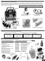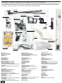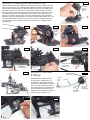
1
Hawk Pro Instruction Manual SPECIFICATIONS Main Rotor Diameter Tail Rotor Diameter Overall Length Height Engine Ball Bearings 49.5 in. 9.3 in. 46 in. 16.2 in. 32 ~ 40 47 Century Helicopter Products Designed and Developed in USA 1st Edition April 2005 All rights reserved. Table of Contents Table of Contents & Introduction ................................................................................................................2 Required Items and Tools for Assembly .....................................................................................................3 Package contents ......................................................................................................................................4 Section 1 Preparing the engine ..................................................................................................................5 Section 2 Assembling the main frame ........................................................................................................5 Section 3 Assembling the servo tray ..........................................................................................................6 Section 4 Fuel tank & fittings ......................................................................................................................6 Section 5 Muffler & fuel tubing ...................................................................................................................7 Section 6 Flybar & rotor head assembly ....................................................................................................7 Section 7 Landing gear ..............................................................................................................................8 Section 8 Tail boom & drive system ...........................................................................................................8 Section 9 Tail boom support struts and tail fin set ......................................................................................9 Section 10 Tail control rod and pitch control ...............................................................................................9 Section 11 Throttle & collective linkage ......................................................................................................9 Section 12 Cyclic servo linkage ................................................................................................................10 Section 13 Rotor head linkage .................................................................................................................10 Section 14 Connect the electronics ..........................................................................................................10 Section 15 Main rotor blade installation ...................................................................................................10 Section 16 Antenna routing ...................................................................................................................... 11 Section 17 Mounting the canopy .............................................................................................................. 11 Main sub assemblies (exploded views) ...............................................................................................12-17 Replacement part list and photos ........................................................................................................18-20 Upgrades .............................................................................................................................................21-22 Introduction Congratulations on your purchase of Century Helicopter Product’s latest version of our HAWK series RC helicopter model. The Hawk Pro helicopter is not only ideal for beginners new to the hobby, but also for the intermediate and right on through to the expert and 3D flyers. A 6 channel helicopter radio is recommended as the bare minimum to take advantage of the helicopter programming included in these radios. You may wish to check with us or your local dealer for compatible components. Warning This radio controlled model is not a toy! It is a precision machine requiring proper assembly and setup to avoid accidents. It is the responsibility of the owner to operate this product in a safe manner as it can inflict serious injury. It is recommended that if you are in doubt of your abilities, seek assistance from experienced radio control helicopter modelers and associations. As manufacturer, we assume no liability for the use of this product. Pre-assembly Information Upon opening the kit, all the major component parts are packaged in numbered bags to correspond to specific sections of the manual, greatly facilitating assembly. Various assemblies have been pre-assembled, only requiring the final assembly and installation of the various sub-assemblies. The screws and nuts required for each step are packaged in the same bag as the parts for that step. Be careful not to lose any of the hardware when opening each bag. Care has been taken in filling and packing of each bag. Warranty Your new equipment is warranted to the original purchaser against manufacturer defects in material and workmanship for 30 days from the date of purchase. During this period, Century Helicopter Products will repair or replace, at our discretion, any component that is found to be factory defective at no cost to the purchaser. This warranty is limited to the original purchaser and is not transferable. This warranty does not apply to any unit which has been improperly installed, mishandled, abused, or damaged in a crash, or to any unit which has been repaired or altered by any unauthorized agencies. Under no circumstances will the buyer be entitled to consequential or incidental damages. This limited warranty gives you specific legal rights. You also have other rights which may vary from state. Century Helicopter Products 1740 Junction Ave. C. San Jose, CA 95112 Fax: (408) 451-1156 2 www.centuryheli.com Required items for operation This is the general list of items required to get started on any nitro R/C helicopter. Century produces a full spectrum of accessories and tools to assemble your helicopter. The Hawk Pro is a mechanical cyclic collective pitch mixing type helicopter requiring a standard helicopter radio (the helicopter radio does not require eCCPM type mixing for this model). The Hawk Pro uses 5 servos to operate critical systems. Gyroscopes are required to operate the model safely. Necessary Items “Not Included” in the kit. Transmitter #PG2000 II dual rate piezo gyro #CN2018 (or eqivalent) Servos (5) Remote Glow Adapter #CN2222 (optional) Receiver Bettery Pack 32-40 Helicopter Engine Tuned Muffler (example #CN3033) 6 Channel Helicopter Radio or Equivalent. Fastener and ball bearing dimensions Hardware Description and Identification: M3x6 Phillips Machine Screw M3x6 = 3x6mm and can refer to screws or ball bearings. M3x6 Self Tapping Screw M3x10 Socket Cap Screw M - metric 3 - diameter 6 - length M - metric 3 - diameter 6 - length 3x7 Ball Bearing M - metric 3 - inside 6 - outside M - metric 3 - diameter 6 - length Recommended Tools & Accessories The tools and materials listed below are the minimum needed to build the helicopter: CN2024T Lubrication In addition, the following will make assembly and setup easier, and prove useful later in your model toolbox: Screwdrivers - Slotted and Phillips head Part#CN2015 Long-Nosed Pliers. Part#CN2026 Allen Wrenches - 1.5mm, 2.0mm, 2.5mm Part#CN2034A ( supplied in kit ) + 3.0mm Part#CN2052 Appropriate Socket Wrench Part#CN2054P (glow plug wrench for engine shaft nut) Part#CN2055 Hobby Scissors Part#CN2070 Double Sided Foam Tape ( 1/16” - 3/32” ) Part#CN2155 Foam Rubber ( radio packing ) Part#CN2219 JB Weld ( bond clutch lining ) Part#CN2255 Thread lock liquid (e.g. Locktite) Part#CNWI26555 Hobby Grease ( Super Lube ) Part#CNWI26570 Oil to lubricate sliding shafts “Y” Harness for 4 Ch Airplane Radio with 5 servo Main Blade Pitch Gauge w/PaddleGauge #CN2026 Hardened Tip Hex Screw Driver Set Pitch Gauge with Paddle Gauge 150 Curve Tip Ball link Pliers Main Blade Balancer Glow Plug Wrench Purple 15% or 30% Ball Link Sizing Tool Heli Fuel Universal Flybar Lock Piston Locking Tool Ball Link Easy Driver Control Rod Guage 5.5mm Nut Driver 7.0mm Nut Driver Hobby scissors Locktite CN2025BS blue CN2025RS red 12Volt Start Battery Fuel Line 12Volt Starter Needle Nose Plier & Cutter Pliers Glow Plug Servo Tape Glow Driver w/Charger Electric or Hand Fuel Pump 3 Package contents: Opening The Hawk Pro for the first time Time to inventory your Hawk Pro! The helicopter is assorted into multiple bags contained inside the box. Each bag will have some parts that are not associated with that specific part bag. We recommend organizing all hardware and pieces and inventory them then keep them with their respective bags. It is common to have a few screws and/or washers left on the side after the build. Tail section Lower frame set Servo frame set Rotor head items Muffler Upper frame set Canopy Hardware/ Pushrods Clutch, fan & shroud Fin pack Main rotor blades Decal sheet Windshield Landing gear Tail section: •Tail assembly (complete) •Tail boom support struts (2) •Flybar (1) *Antenna tube (1) •3x8 flat washers (4) •Rudder servo mount bracket (1) •3x30 socket head cap screws (2) •Grey ball link (1) (rudder pushrod forward end) •Servo mounting tabs (7) •Throttle pushrod (1) •M2 short balls (7) (servo arms) •M2 nut (7) (servo arms) •3x25 socket head cap screws (4) •M3 locknut (4) Rotor Head Items: •Rotor head (complete) •Flybar paddles (2) •Paddle weights (2) •3x3 set screws (2) (for paddle weights) •Flybar control arm (2) •Double link (2) (flybar to washout arm) •4x5 set screws (2) (flybar control arms) •3x6x2.5 plastic spacer (2) (between flybar control arm and seesaw) •3x7x3 ball bearing (2) (flybar, inside seesaw bearing cups) Clutch, fan & shroud: •Clutch (clutch and housing) (1) •Cooling fan (1) •Cooling fan shroud (1) •Long aluminum tube (1) •Short aluminum tube (1) •Fuel fitting set (1 set) •Tie wrap (1) •Clunk (1) •3x18 self tapping screw (1) (fuel cap) •5 inches fuel tubing (1) •5x13 flat washer (1) (between cooling fan and engine nut) •9x14 flat washer (1) (replaces thrust washer on engine) •3x16 socket head cap screws(4) •3x8 self tapping screws (2) •3x12 self tapping screw (2) •3x6 washer head screws (2) Fin pack: •Vertical and horizontal fins (1ea.) •tail rotor blades (2) •3x16 socket head cap scews (4) •M3 locknut (6) •3x8 self tapping screws (2) (fin clamp underside) •3x8 flat washer (4) •3x9x4 thick spacer (2) (boom support to frame) •3x30 socket head cap screws (2) (vertical fin) Upper frame set: •Upper side frame assembly (complete) •Aluminum canopy standoff (2) •Canopy grommets (2) •Canopy hook (1) (inside canopy) •3X40 threaded rod (1) (canopy standoffs) •Horizontal fin upper clamp (1) (white plastic part that connects to fin) •M3 lock nut (1) •3x20 Socket head cap screw (1) •M3 locknut (1) •3x6 self tapping screw (2) (connects lower side frame to fan shroud) •3x12 Self tapping screws (4) (for servos) •3x16 Socked head cap screws (4) (not used/spares) 4 Hardware/Pushrods: •1 foot fuel tubing (1) •Pushrods (5) •4x30 Socket head cap screws (2) (main blade bolts) •M4 locknut (2) •2.5x12 self tapping screws (20) (servos) •Throttle lever (1) •Metric allen key (3) Landing gear: •Landing struts (2) •Landing skids (2) •M3 locknut (4) •3x20 socket head cap screws (4) •3x9x4 plastic landing gear spacer (4) •3x4 set screw (4) Canopy (1) Windshield (1) Decal sheet (1) Lower frame set (1) Servo frame set (1) Muffler (1) Main rotor blades (1 pair with hardware) Section 1: Preparing the engine 1.1 Remove the thrust washer that comes on the engine from the factory. Only use the 9x14 washer that comes with the fan and clutch package. Mount that washer first and the clutch (1.1-1.2) to the engine using thread lock. Mount the fan so the two protruding portions on the underside slide into the slots machined in the clutch (1.3). Remove the stock engine throttle arm and use the one provided with the helicopter kit. (packed with the fuel hardware/pushrods pack). Place the 6.5x13 Washer (packed with fan and clutch also) between the fan and the crankshaft nut and tighten using thread lock (1.4). In order to tighten the assembly properly, the piston must not be allowed to turn (you can use the optional #CN2155 piston locking tool). 1.2 Clutch Must use RED (strongest) lthreadlocking compound for engine installation. 1.3 Cooling fan Crankshaft nut provided with engine 1.4 Piston locking tool (optional) #CN2155 M9x14 washer Section 2: Assembling the main frame Using thread lock, mount the engine assembly to the engine mount in the lower side frame assembly (2.1). After the engine is installed, combine the upper and lower side frame sections (2.2) Before bolting, attach the fan shroud securely to the frame assembly slightly overlapping the fan shroud portion of the upper side frames (2.3). Use hardware provided to finish assembling the frames. (2.4 & 2.5). Install the canopy mounting hardware (2.6 & 2.7) by first threading one end of the threaded steel rod into one of the aluminum standoffs. Insert the aluminum standoff and rod into the frame (2.6) and thread the other standoff (2.7) on until tight. The upper and lower frames are now assembled (2.8). 2.1 2.2 2.3 M3x16 socket head cap screw (x4) 2.4 M3x12 socket head cap screw (x4) M3 Washer (x4) 2.5 M3x6 self tapping screw (x2) Canopy aluminum standoffs (x2) Threaded rod (1X) 2.6 The M3x12 screws in this step are stapled to your manual or kit. 2.7 2.8 Note: IMPORTANT: Motor mount screws DO NOT have thread lock yet. Loosen these screws to position the motor or replace with optional #HW3018A for .50 size engines. 5 Section 3: Installing servos to servo tray 3.1 Insert and attach the lower throttle servo on the left side (3.1) with the output “horn” facing the front of the servo tray. Install the upper collective servo above the throttle servo with the output facing the back (3.2). Attach the aileron servo (3.2) to the middle of the top portion of the servo tray with the horn facing forward. Attach the elevator servo to the left of the aileron servo horn facing rearward (3.2). Attach the power switch (3.3) to the switch plate provided on the right hand side of the servo frame. Slide the gyro in place (3.4). If possible, expose the gyro’s manual controls for future easy adjustment. Attach the servo frame assembly to the main frame assembly forward section (3.5 - 3.6) using provided hardware. Attach the rear rudder servo mount to the right hand aft section of the upper side frame with the output facing rearward (3.7). Completed section (3.8) depicted. install servos with M2.5x12 self tapping screws nt Fro Aileron servo 3.2 Elevator servo 3.3 3.4 Screws for switch are provided with switch in radio system Collective pitch servo Throttle servo 3.5 Use thread lock M3x6 washer head screws (2) 3.8 3.6 3.7 M3x25 socket head cap screws (2) M3 locknut (2) 3x12 self tapping screws (2) Section 4: Fuel tank & fittings Short straight tube (sends fuel to engine) fuel tank pickup “clunk” Assemble the fuel stopper (found in the bag with the upper frames) (4.1) by bending the longer aluminum tube (connects to muffler nipple) so it will end at the top inside the fuel tank. Align the short straight aluminum tube level to the engine carburetor fuel intake. Secure with M3x18 screw supplied in clutch/fan package and tie wrap (4.2 & 4.3) 4.2 Fuel line Long curved tube (from muffler nipple) Fuel fitting set assembled 4.3 Tie wrap 6 4.1 M3x18 self tapping screw Section 5: Muffler & fuel routing 5.1 Using thread lock: Hardware provided with muffler Install the pressure nipple using a high temperature adhesive (thread lock) to the top of the muffler and the 4mm plug screw to the bottom (5.1). Bolt the muffler to the engine (5.2) flush (no gasket required) using thread lock. Connect fuel tube between the fuel pickup in the tank and the carb on the engine with as little slack as possible (5.3). Connection between the carb and the fuel pickup tube (short straight) should be level (keeps fuel draw rate in inverted flight). Connect the fuel tank air tube (long curved) to the muffler pressure nipple (5.3). Using thread lock: 3x25 socket head cap screw (2) (Optional Toki muffler for Toki .40 engine shown. Toki muffler is supplied with a Hawk Pro “Toki engine and muffler combo”) 5.4 5.3 5.2 Section 6: Flybar & head assembly Install the flybar, flybar control arms, weights and paddles into the rotor head seesaw assembly as shown (6.1). First slide the flybar in place through the seesaw assembly. Then slide the ball bearings included with the two ball bearings into the seesaw cups on each end. Then slide the M3x6 plastic spacers on to each side of the flybar. Next slide the 2 flybar control arms as shown (6.1) Use thread lock on the set screws connecting the flybar weights to the flybar (6.2 - 6.3). Align the flybar paddles and control arms level to the seesaw assembly (LEADING EDGE OF PADDLES MUST GO CLOCKWISE). The assembled flybar must be the same length on each side of the rotor head. Install the completed rotor head to the main shaft (6.4) with one 3x16 cap screw and M3 locknut. M3x7 Ball bearing (2) M3x6 spacer (2) Flybar control arm 6.3 Using thread lock M3x3 set screw (2) M4x5 Set screw Trailing edge Flybar weight Leading edge Seesaw assembly (bearing cup) 6.2 Using thread lock M4x5 set screw (2) 6.1 Flybar paddle M3x4 Set screw 6.4 M3x16 socket head cap screw (1) M3 locknut (1) 7 Section 7: Landing gear 7.1 All components for installing landing gear are included with the landing gear bag. Attach the plastic U shaped struts to the bottom of the main frame and insert the metal skids when aligned (7.1). Bolt the landing gear to the main frame using provided hardware (7.2). Attach the skids only when helicopter will sit level using the provided set screws and CA glue (7.3). At the end of this section the helicopter should be able to stand upright (7.4). M3x16 socket head cap screws (4) M3 Locknut (4) 7.2 M3x4 socket head set screws (4) CA Glue 7.3 Section 8: Tail boom & drive system The tail section (8.1) is completely assembled and only requires to be attached to the main frame (use a small amount of gear grease inside the tail gearbox). Slide the tail boom into the aft section of the main frame with the tail rotor on the right side of the helicopter (8.2) twisting slightly until the notches in the tail boom align with the standoffs on the inside of the main frame. Once installed, the drive system should be complete and the main/tail blades should rotate when the main gear is turned. Attach the tail blades to the tail blade grips (8.3) using the hardware provided. 7.4 8.1 Remove the 3 socket head cap screws to open the gearbox in order to grease the gears. Note: Place a small dab of gear grease (synthetic hydrogen grease) between the two plastic gears. White coupler located inside the upper frames 8.3 M3x30 socket head cap screws (2) M3 Locknut (2) 8.2 M3x16 socket head cap screws (2) M3 Locknut (2) 8 Section 9: Tail boom supports & tail fin set 9.1 Attach the tail boom support struts to the base of the side frames using the plastic spacer on the outside of the frame (9.1) . Attach the horizontal fin (hardware found inside fin bag) and tail boom supports onto the horizontal boom clamp (9.2 use the white plastic piece found with the canopy grommets between the fin clamp and the fin). Screws are provided for mounting the vertical fin in the package containing the fins (9.3). M3 plastic spacer (2) M3x16 socket head cap screw (2) M3 locknut (2) 9.2 9.3 M3x12 Self tapping screw (2) 9.4 M3x20 socket head cap screw (2) M3 locknut (2) M3x8 Self tapping screw (2) M3 washer (2) Section 10: Tail control rod & pitch control 10.1 Use the radio to center the rudder servo. Mount the servo arm/horn perpendicular to the tail pitch control rod threading the forward tail control rod ball link (found in the upper frame bag) onto the pushrod (10.1). Adjust link at rear of tail system so that the tail pitch slider is roughly centered on the tail output shaft (10.2). Connect the ball links to the control balls at either end only when the rudder servo is centered and the pitch slider is centered. Align the tail pushrod guides to help keep the pushrod traveling without flex (10.3). Fix the favorable positions of the pushrod guides (use CA glue) to avoid shifting/binding. Pushrod should travel through the horizontal fin clamp on the right side (10.2 & 10.4). 10.2 Rudder servo 10.3 10.4 Rudder pushrod should travel through the tail boom clamp guide (this is the way it is pre-assembled). Guides should be helping the pushrod keep it’s shape when being flexed. All 3 guides may not have to be used. Section 11: Throttle & Collective linkage *Pushrod measurements include ball links from plastic end to plastic end. Before any pushrod adjustments are made center both sticks and all servos on the transmitter. Attach the 103mm throttle control rod to the throttle servo and the throttle arm on the carburetor. Be sure that when the throttle collective stick is in the middle, that the throttle servo arm is straight up, and that the carburetor barrel is half open and its control arm is also pointed straight up. Adjust the collective control rod to 102mm for training or to 100mm for 3D. Attach this rod to the collective control lever and collective servo. Be sure the collective servo wheel is attached so that at mid stick it is pointed straight up. Collective pitch servo Throttle servo 9 Section 12: Cyclic servo linkage Aileron servo Before any pushrod adjustments are made center both sticks and servos on the transmitter. *Pushrod measurements include ball links from plastic end to plastic end. Adjust the two aileron control rods to 158mm and attach the two balls on the aileron servo wheel and to the two aileron bellcranks. Adjust the elevator control rod to 135mm and attach to the elevator servo arm and elevator bellcrank. Elevator servo Section 13: Rotor head linkage Before any pushrod adjustments are made center both sticks and servos on the transmitter. *Pushrod measurements include ball links from plastic end to plastic end. Attach two 104mm pushrods to the short balls on the swashplate and to the short balls on the bell mixers on the main rotor blade grips. NOTE: For faster cyclic response in 3D you may want to change the bell/hiller ratio by moving the A-arms from the washout assembly to the short balls on the inner star of the swashplate and attach these 106mm rods to the longer balls on the inner star. Section 14: Connect the electronics Refer to the instructions for your transmitter and other radio components for the correct numbering of channels before connecting . Plug in the switch, servos and gyro to the radio receiver. Wrap the receiver and the battery pack with the proper foam protection recommended by your radio manufacturer and secure to the top of the battery/receiver platform at the lower front of the servo tray (use #64 rubber bands). Section 15: Main rotor blade installation 15.1 Each rotor blade has 3 holes drilled in the root. Use epoxy to glue the plastic root ends to the exposed wood pre-cut by the factory (15.1). Use the countersunk screws (15.2) to secure the root ends to the blades and let the glue dry. Use the 2 M4x30 blade bolts and M4 locknuts to secure the blades to the blade grips on the main rotor head (15.3). Main rotor blades should have their leading edge turning clockwise. 15.2 Blade bolt hole Countersunk blade root screws (4) Trailing edge Leading edge 10 15.3 M4x30 Socket head cap screws (2) M4 Locknut (2) Section 16: Antenna routing Thread the small clear tube into the guides (located on the right bottom side of the struts) on the side opposite the muffler. Insert the receiver antenna into the tube and secure to the rear area of the tail boom or one of the boom support struts. It is recommended that you use a small rubber band to do so. Section 17: Mounting the canopy 17.1 Carefully cut out the windshield area from the canopy (17.1) with a sharp hobby knife. Trial fit the canopy and mark the location of the front lower mount (17.2), drill the two required holes and attach to the inside of the canopy with the screws and washers provided. Mount the front of the canopy (17.3) and mark the location of the top rear mounts. Drill the 1/4 “ holes and insert the grommets (17.4). Cut out the windshield along the marked lines (17.5) and install onto the canopy with the six small screws supplied. Cut out the decals for the canopy from the decal sheet and attach to the canopy (17.6) Then mount the canopy on the helicopter. 17.2 17.4 17.3 Mark location Canopy hook found with upper side frame set bag 17.5 Rubber grommets found in upper side frame set bag. 17.6 The completed model Your helicopter is assembled, your engine, servos, gyro and receiver installations are complete. Now you will have to refer to your engine manual for starting and running instructions, your gyro manual for set-up instructions and your radio manual for the transmitter set-up instructions. 11 Main Sub-Assemblies This section will overview parts that came pre assembled from the factory. Items not attached to main sub assemblies can be found in the parts list. Main Rotor Head Main head block #HI3160B Feathering shaft #HW3180 Seesaw pivot shaft set #HW3161A (inside main head block) #CNBB1030 Seesaw set #HI3167A Bell mixer arm set #HI3189 Ball bearing Rubber dampers (2) 5x13 #HI3181 #CNBB1350 Damper spacer set #HW3180B Seesaw pivot shaft Washout pins (2) #HW3170A Main blade grip (2) #HI3167D Flat washer 5x10 Flat washer 4x12 Flat washer 4x10 Ball bearing 5x13 #CNBB1350 M3x6 button socket screw (2) Seesaw set Special ball (2) #HI3167E M3x7 ball bearing (2) CNBB0730 Tie bar (2) #HI3167C Seesaw pivot shaft set #HW3161A Upper Side Frame Interior Ball bearing #CNBB1030 (2) Main shaft #HW3053A M19x14 spacer #HI3107A Ball bearing 10x19 #CNBB1019 Main shaft collar #HW3054A Alloy drive gear #HW3045 Ball bearing 5x13 #CNBB1350 M3x4 Set screw Main gear #HI3056 Offset plate (2) #HI3167B seesaw pivots on seesaw pivot Bearing cup shaft here (2) #HI3167D Tail rotor output gear #HW3057 Torque tube coupler #HI3154 Tail drive output shaft & spacer #HW3059A M3x4 Set screw M5x7 Spacer (2) Ball bearing 5x13 #CNBB1350 Counter drive shaft #HW3042 M3x16 socket head cap screw M3 locknut Ball bearing 8x19 #CNBB1980 Ball bearing 5x13 #CNBB1350 M2x12 pin 12 Counter gear #HI3040 M4 locknut Autorotation bearing set #HW3050 (inside main gear) Bell mixer arm Bell mixer arm #HI3189A Short ball #CNLR1011 M3 spacer (2) M3 washer (2) M3x7 ball bearing (2) #CNBB0730 Long ball #CNLR1012 Upper Side Frame Exterior M3x16 Socket cap screw (2) Washout arm set #HI3152C (comes assembled uses #CNBB0730 Ball bearing) M3x7 ball bearing (2) #CNBB0730 Swashplate set #HI3146B Elevator lever set #HI3032C Hex start adapter #CN0402 Start shaft set (with spring) #CN2226 Start shaft bearing blocks #HI3007 (uses 2 #CNBB1150 5x11 ball bearings) Aileron bellcrank set (2) #HI3031A (uses 2 #CNBB0730 ball bearing) Collective pitch lever set #HW3024 Upper side frame set #HI3107 13 Collective pitch lever Swashplate set #HI3146B M3x5 flat washer Aileron bellcrank set #HI3031B M3x7 ball bearing (4) #CNBB0730 (2 per bellcrank) M6x10 ball bearing (2) #CNBB1060 Collective lever set #HW3024 Elevator lever set #HI3032B M3x5 flat washer M3x30 socket head cap screw (2) Aileron bellcrank set #HI3031B Collective lever set #HW3024 M3x10 socket head cap screw (4) (2 on each side) Collective lever set #HW3024 14 Flybar assembly M3x7 ball bearing (2) CNBB0730 Flybar control arm set #HI3176 M4x5 Set screw M3x4 Set screw Flybar paddle set #HI3179 Flybar #HW3173 Main gear Starter shaft Autorotation bearing set #HW3050 (inside main gear) Hex start adapter #CN0402 M3x4 set screw using thread lock Hardened start shaft (with spring #HW3005A M5x10 collar M3x4 set screw Spring between collar and M5x10 flat washer Main gear #HI3056 M5x10 flat washer (between spring and lower bearing block) Autorotation bearing set #HW3050 (inside main gear) 15 Lower Side Frames Servo Side Frame Set Servo side frame set #HW3115A Lower side frame set #HW3112C Front canopy mount set #HI3129 Fuel tank set #HI3138A Engine mount #HW3017 Tail Section Interior Torque tube collar (also includes male end from page 17) #HI3065 Tail drive shaft set #HW3063TS Tail gear box (left & right) #HI3078 Tail gear box input shaft #HW3070A Tail rotor hub #HW3098 Ball bearing 5x11 #CNBB1150 Ball bearing 5x11 #CNBB1150 Ball bearing (2) 5x13 #CNBB1350 16 Tail gear set #HI3075 Tail output shaft #HW3073 Tail output spacer #HW3074 Tail pitch lever Tail pitch plate Tail pitch plate assembly #HI3087A M2 short ball on tail pitch plate connects here M3x16 socket head screw connects here Tail pitch plate assembly #HI3087A Tail pitch plate assembly (brass slider) #HI3087A M3x16 socket head screw Ball bearing M6x10 (2) #CNBB1060 Tail pitch ball link set #HI3089 Tail pitch lever set #HI3102A Tail drive shaft Torque tube male end (also includes collar from page 16) #HI3065 Tail Blade Grips Torque tube bearing case #HI3065A Ball bearing M8x16 #CNBB816 Tail Section Exterior M2x10 phillips machine screw (4) M3x4 set screw Tail rotor hub #HW3098 Torque tube shaft set #HW3063TS Torque tube shaft only #HW3063S M3x10 socket head cap screw (2) Ball bearing 3x10 #CNBB1030 (inside tail blade grips) Tail blade grip set #HI3096 Tail pitch plate #HI3087A Tail pitch ball link set #HI3089 M3x10 Ball bearing (2) #CNBB1030 M2 hex nut (4) Tail pitch lever set #HI3102A Horizontal fin clamp #HI3201-1 Tail boom #HW3062 Tail control rod guides (3) #HI3106A Tail control rod set #HW3064G 17 Hawk Pro Replacement Parts CN2230H4 CRASH KIT -(Main Blades, Main Shaft, Tail Boom, Feathering Shaft and Flybar) HW3000 HARDWARE PACK CN0402 HEX START COUPLER HW3005A STARTER SHAFT SET HI3007 STARTER SHAFT BEARING BLOCKS HI3009 COOLING FAN HI3010 CLUTCH BELL & LINING HW3011 CLUTCH SHOES HW3017 ENGINE MOUNT HI3020 COOLING FAN SHROUD HW3024 COLLECTIVE PITCH LEVER SET HI3031A AILERON BELLCRANKS (L&R CYCLIC) HI3032B ELEVATOR LEVER SET (LONG) HI3032C ELEVATOR LEVER ONLY (LONG) HI3035A ADJUSTABLE CYCLIC PUSHROD LINKS HI3040 COUNTER DRIVE GEAR HW3042 PRIMARY DRIVE SHAFT HW3045 ALLOY DRIVE GEAR 13T HW3050 AUTOROTATION BEARING SET HW3053A 10mm MAIN SHAFT HW3054A 10mm MAIN SHAFT LOCK RING HI3056 MAIN GEAR HW3057 TAIL DRIVE BEVEL GEAR HW3059A TAIL DRIVE PRIMARY SHAFT HW3062 TAIL BOOM HW3063TS TAIL DRIVE SHAFT & MALE END HW3063S TAIL DRIVE SHAFT ONLY HW3064G TAIL PITCH CONTROL ROD HI3065 TORQUE TUBE MALE END WITH COLLAR HI3065A TORQUE TUBE BRG. HOLDER WITH O-RING HI3067A TAIL FIN SET HW3070A TAIL GEARBOX INPUT SHAFT HW3073 TAIL GEARBOX OUTPUT SHAFT HW3074 TAIL GEARBOX SPACER TUBE HI3075 TAIL GEAR SET HI3078 TAIL GEARBOX L&R HI3087A TAIL PITCH SLIDER SET HI3089 TAIL PITCH BALL LINKS HI3096 TAIL BLADE GRIP SET HW3098 TAIL ROTOR HUB HI3099 TAIL ROTOR BLADES (PAIR) HI3102A TAIL PITCH LEVER SET HI3106A TAIL CONTROL ROD CLAMPS HI3107 UPPER SIDE FRAMES HI3107A 10mm BEARING SPACER 14x19x1 HW3112C LOWER SIDE FRAMES HW3115A SERVO MOUNT FRAME SET 1 1 1 1 1 1 1 1 1 1 1 2 1 1 2 1 1 1 1 1 1 1 1 1 1 1 1 1 1 1 1 1 1 1 1 1 1 2 1 1 1 1 3 2 2 2 2 Hawk Pro Upgrade Parts & Accessories CN0427 CN2005 CN2007A CN2015 CN2016 CN2018 CN2022 CN2046 CN2052 CN2056 CN2079 CN2137 CN2155 CN2153 CN2176 CN2177 CN2179H CN2202 CN2275 18 Hex start wand with one-way bearing Main Blade Transport Supports Trainer Pod 30-50 w/4 Legs Hardened Tip Hex Wrench Set (1.5mm/2.0mm/2.5mm/3.0mm tips) 4.8V Battery Monitor/Alarm PG-2000II Dual Rate Remote Gain Piezo Gyro Single rate micro piezo gyro Basic Heli Setup Tool Kit (pitch gauge, blade balancer & pliers) Accuratech Blade Balancer -blue CNC Machined Aluminum Swashplate Fast 3-D Hot dog fly bar paddles (R red, O orange, Y yellow) 2 oz Header Tank w/ Universal Bracket -purple Piston Locking Tool - purple Machined Throttle Extension - OS32SX,46FX, TT36H -purple CNC machined servo arm pack (5 pcs. Futaba purple) CNC machined servo arm pack (5 pcs. JR purple) CNC machined servo arm pack (5 pcs. Hitec purple) Aluminum Turbo cooling fan - purple CNC Machined Bell Mixing Arms (2) HI3122 HW3123 HW3127A HI3129 HI3130B HI3131M HI3133A HI3138A HI3145 HI3146B HI3152C HI3152A HI3160B HW3161A HI3167A HI3167B HI3167C HI3167D HI3167E HW3170A HW3173 HI3176 HI3179 HW3180C HW3180B HI3181 HI3184 HI3189A CN2322 HW3192 HW3202B HW3204 CNBB0730 CNBB816 CNBB1019 CNBB1030 CNBB1060 CNBB1150 CNBB1350 CNBB1150 CNBB1980 CNBB1218 HW3050 CNLR1014 CNLR1015 CNLR1016A CNLR1013 CN3033A LANDING STRUTS (PLASTIC) LANDING SKIDS (METAL) HEX SPACER & CANOPY MOUNT SET CANOPY MOUNT & HARDWARE CANOPY HAWK PRO DECAL SET CLEAR WINSHIELD (for HI3130B) FUEL TANK BALL LINKS (16 LONG & 6 SHORT) SWASHPLATE WITH STEEL BALL END WASHOUT SET RADIUS LINK WITH PIN ROTOR HEAD BLOCK FLYBAR SEESAW SHAFT SET FLYBAR SEESAW COMPLETE SET SEESAW OFF SET PLATE SEESAW TIE BAR SEESAW BEARING CUP SPECIAL BALL M3X6 WASHOUT PINS FLYBAR STABILIZER CONTROL ARM FLYBAR PADDLES FEATHERING SHAFT DAMPENER SPACER SET DAMPING RUBBERS ROTOR BLADE GRIP MIXING ARM SET MAIN ROTOR BLADES (PAIR) LINKAGE SET (11 RODS) T/B SUPPORT STRUTS (PAIR) THROTTLE EXTENSION Bearings 3X7X3 (Flybar,Elevator Lever) Bearing tail drive shaft Bearings 10X19X6 (Top Main Shaft) Bearings 3X10X4 (Seesaw,Tail Grips) Bearings 6X10X3 (Collective Axle, Pitch Plate) Bearings 5X11X4 (Start Shaft,Tail Shaft) Bearings 5X13X4 (Counter shaft,Blade grips) Bearings 5X11X4 (Start Shaft, Tail Shaft) Bearings 8X19X6 (BottomMain Shaft) Bearing 12x18x4 (Clutch Bell) Autorotation Bearing 12X18X16 Stainless M3 Ball joint with short standoff Stainless M3 Ball joint with medium standoff Stainless M3 Ball joint with long standoff M2 Ball joint with short standoff Black Torpedo Muffler 32-40 2 2 1 1 1 1 1 1 1 1 1 2 1 1 1 2 2 2 2 2 1 2 2 1 2 2 2 1 1 1 1 1 2 1 2 2 2 2 2 2 2 1 1 2 2 2 2 1 CN2208B Metal Swashplate Anti-rotation Bracket - black CN2208P Metal Swashplate Anti-rotation Bracket - purple CN2213 2oz Header Tank w/ Machined Mount Bracket - purple CN2214B Air Filter (OS32-46, TT36-46) CN2215B Machined Head Button (threaded) - black CN2215P Machined Head Button (threaded) - purple CN2217P Machined Color Caps - purple CN2218P Machined Color Washers - purple CN2221 6mm Feathering Spindle System w/ Thrust Bearings CN2126H Ultra Light Carbon Graphite Tail Boom CN2239C Carbon tail boom mount for rear rudder servo CN2240H Carbon Graphite 3D Tail Fin Set CN2128H Ultra Light Carbon Graphite Tail Boom Supports CN2400 Hurricane Carbon fiber Blades - 550mm Fully Sym CN2501 Vortex Carbon fiber Blades - 550mm Fully Sym 3D Pro CN265522 RotorTech Carbon Blades - 550mm Fully Sym 3D Sport CN3033 Speed torpedo 30 HV Muffler - Polished Aluminum CN3055H Millennium Pipe System - Polished Aluminum See page 19-20 for upgrade photos. Hawk Pro Replacement Parts HW3000 Hardware pack HI3010 Clutch bell HI3031A Aileron bellcrank set HW3045 Alloy drive gear HW3057 Tail transmission bevel gear HI3067A Tail fin set HI3078 Tail gearbox CN0402 Hex start adapter HW3011 Clutch shoe HI3032B Elevator lever set HW3050 Autorotation bearing set HW3059A Tail drive primary shaft HW3070A Tail gearbox input shaft HI3087A Tail pitch slider set CN2226 Hardened start shaft HW3017 Engine mount (.30 size) HI3035A Adjustable cyclic link set HW3053A Main shaft HW3062 Tail boom pipe HW3073 Tail output shaft HI3089 Tail pitch ball links HI3007 Starter bearing blocks HI3020A Cooling fan shroud HI3040 Counter drive gear HW3054A Main shaft collar HW3063TS Tail drive shaft & male end HW3074 Tail output shaft spacer HI3096 Tail blade grip set HI3009 Cooling fan HW3024 Collective pitch lever set HW3042 Primary drive shaft HI3056 Main gear HW3064G Tail control rod HI3075 Tail gear set HW3098 Tail rotor hub 19 HI3099 Tail rotor blades HW3115A Servo frame set HI3130B Canopy HI3146B Swashplate set HI3167A Seesaw lever set HW3170A Washout pins HI3181 Dampening rubbers 20 HW3204 Throttle lever HI3102A Tail pitch lever HI3122 Landing struts HI3131M Decal set HI3152C Washout unit HI3167B Seesaw offset plate HW3173 Flybar HI3184 Main rotor blade grips CN2322 Main rotor blades HI3106A Tail pushrod guides HW3123 Landing skids HI3133A Windshield HI3152A Radius links HI3167C Seesaw tie bars HI3176 Flybar control arm set HI3189A HI3107 Upper side frame set HW3127A Canopy frame mounts HI3138A Fuel tank parts set HI3160B Main rotor hub HI3167D Seesaw Bearing cups HI3179 Flybar paddle set HW3192 Bell mixing arms Cyclic pushrod set HI3107A HI3065A M9x14 spacer (upper frames) Torque tube bearing case HI3112C Lower side frame set HI3129 Canopy front mounts HI3145 Ball link set HW3161A Seesaw pivot lever HI3167E Special ball M3x6 HW3180C Feathering shaft set HW3202B Tail boom support set HI3065 Torque tube male end Century Hawk Pro Upgrades Fiber Glass Whip Antenna CNC Machined Aluminum Servo Arm Pack Color Machined Finish Cap & Washer (for plastic output/gear servos) Kit comes with a hollow fiber tube and CNC base mounts that allow you to insert antenna into the tube. Antenna will be better protected and look so cool. CN2124-NG Antenna Neon Green CN2124-NY Antenna Neon Yellow Completely eliminate slop from flexing servo arms (purple) CN2176 (Futaba) Arm set CN2177 (JR/Air) Arm set CN2179H (Hitec) Arm set Tuff landing Gear Systems Reversible Hex One Way & Hex Start System 3 times stronger then most 30-50 size helicopter landing gear. Tuff struts act as shock absorbers to help reduce jolts caused by hard landing. Adapts to starter shaft push into rubber insert. Extension adapts to most starters. CN2243 Tuff landing gear Neon Color 3-D Paddles CN0426 CN0427 Standard hex wand One-way hex start ext. 3-D Carbon Fin set Speed up your 3D cyclic response with these lightning quick paddles! CN2079Y (Neon Yellow) CN2079R (Glow Red) CN2079O (Glow Orange) Carbon Fiber Tail Boom Get that attractive woven Carbon Fiber look with these light carbon fiber tail booms CN2126H Carbon tail boom 3D Hot Dog pilots will love this light and durable carbon fiber tail fin set. CN2240H Tail Fin set O.S. Throttle Extension Aluminum C.N.C. machined throttle extension for OS32SXH, 46FXH and TT36H (purple) CN2153 Throttle extension These caps and washers will add a lot to the looks of our Hawk Pro (colors: Silver, Red, Blue, Gold, Purple, green, black 10pcs/pack) CN2217B (screw cap blue) CN2218R (nut washer red) Color Machined Lock Nut w/Flange (color: silver, red, blue, gold, purple & black 10pc pack. CN2211B lock nuts blue CN2211BK lock nuts black CN2211R lock nuts red CN2211G lock nuts green CN2211S lock nuts silver Main Shaft Thrust Bearing Kit Transfers all loading from the regular radial bearings to the thrust bearing. CN2220A Thrust Bearing Kit Crash Kit Triple Ball Bearing Tail Blade Grips & One Piece Steel Hub Heavy duty dual B.B and a trust bearing tail grip permits solid precise control. One piece hardened steel hub for long-lasting precision and durability. CN2235 Triple B.B tail assembly Millenium Tuned Pipe System This tuned pipe flattens the power band while boosting additional 1015% of the overall power from the engine. CN3055H Tuned Pipe Set 50 size engine motor mount Convert side frames to take up to the O.S. 50 Engine CN2251 O.S. 50 Conversion Carbon Graphite Tail Boom Support Hawk Pro crash kit includes 550mm main blade, tail boom,feathering shaft, Super high quality, extremely light weight and ready to install dual tail 10mm main shaft, flybar. boom support kit. CN2230H4 Hk Pro crash kit CN2128 Carbon Support 21 Century Hawk Pro Upgrades Head Button (Hawk, Falcon & Phoenix) Fiber Glass Canopy with Carbon Support Metal Bell Mixer Arm Set 2 oz Header Tank w/ CNC Machined or Die-cut Mount Left hand threaded Black or Purple anodized head CN2213 button for easy stopping of the rotor head. Remove slop tranferring to blade grips. CN2215B Black CN2215P Purple 4mm Flybar upgrade More rigid and precise flybar improves cyclic response CN2232 4mm flybar upgrade Constant Tail Drive Descending or in autorotations, full tail rotor control is maintained in proportion to the main rotor speed. CN2263A Constant Tail Drive Extra hard Rubber dampeners CN2242B CN2242G CN2242Y Light Bule Light Green Light yellow CCPM Conversion Outstanding for rigid, slop free elevator control. CN1061A CCPM conv. 10mm Aluminum Clutch Bell CN2275A Metal color CN2275P Purple color Aluminum Turbo Cooling Fan Increased air flow, lower engine drag, cooler and smoother high speed operation & cooler clutch shoes. CN2202 Turbo cooling fan Precision Metal Swashplate CNC precision machined aluminum clutch bell with replaceable gear and lining CN2225 Clutch bell w/gear HI3010A Bell only HI3010B 2-Stroke Gear (26T) CN2020L Clutch lining (2) RotorTech Carbon High performance main blades CN2137 Get 2 extra ounces of fuel and reduce any fuel foaming in one easy step! CN2213 CN2137 Machined Mount Die Cut Mount Metal Swash Plate Anti-rotation Bracket Improves timing precision of the swash plate (purple or black) CN2208P CN2208B Purple Black SE 6 mm Head Axle with Thrust Bearings The 6mm spindle takes the high “G” stresses of 3D better and the thrust bearings make for smoother pitch control at high rotor speeds This beautiful CNC precision machined aluminum swashplate will increase precision control for all flight maneuvers. (Silver) CN2056 Metal Swashplate CN2221 Conversion Kit RotorTech Carbon High performance tail blades Get extra supercrisp flying with hard cyclic dampeners. Soft fluttering will switch to lightning quick response Century Helicopter Products 1740 Junction Ave. C. San Jose, CA 95112 Fax: (408) 451-1156 www.centuryheli.com HI3181A 85 degree hardness damping rubbers The ultimate competition winning carbon blade. 6 out of 10 professional pilots choose RotorTech! CN265501 carbon angle tip 550mm CN265522 carbon flat tip 550mm The ultimate competition winning carbon tail blade. Maximum tail control is yours! CN260853 carbon tail blades 85mm All rights reserved. No part of this publication may be reproduced, stored in a retrieval system or transmitted in any form or by any means, electronic, mechanical, photocopying, recording or otherwise, without the prior written permission of the publisher, Century Helicopter Products. 22