1
™
WeR@Home
System
User Guide
ESUG05022
Version 3.4
September 2014
Legal Notice
Usage of this document, and all information (including product information) provided within, are subject to the following terms and conditions, and all applicable
laws. If you do not agree with these terms, please do not access or use the remainder of this document.
This document contains highly confidential information, which is proprietary to Essence Security International (E.S.I.) Ltd. and/or its affiliates (hereafter, "Essence").
No part of this document's contents may be used, copied, disclosed or conveyed to any third party in any manner whatsoever without prior written permission from
Essence.
The information included in this document is intended for your knowledge and for negotiation purposes only. Essence makes no implicit representations or
warranties with respect to such information.
The information included in this document is subject to change without notice. Any decision to rely on the information contained herein shall be at your sole
responsibility, and Essence will not accept any liability for your decision to use any information or for any damages resulting therefrom.
Certain laws do not allow limitations on implied warranties or the exclusion or limitation of certain damages. If these laws apply to you, some or all of the above
disclaimers, exclusions, or limitations may not apply to you.
By using the information contained herein, you agree that the laws of the State of Israel, without regard to principles of conflict of laws, will govern any dispute of
any sort that might arise between you and Essence regarding the information contained herein, and any such dispute shall be settled exclusively in the competent
courts of Tel Aviv-Jaffa, Israel.
All registered or unregistered trademarks, product names, logos and other service marks mentioned within this document are the property of Essence, or their
respective owners. Nothing contained herein shall be construed as conferring by implication, estoppels, or otherwise any license or right, either express or implied,
under any patent or trademark of Essence or any third party. No use of any trademark may be made without the prior written authorization of Essence.
This document and all of its contents are protected intellectual property of Essence. Any copying, reprinting, reuse, reproduction, adaptation, distribution or
translation without the prior written permission of Essence is prohibited.
Please check your End User License Agreement (EULA) for terms and conditions.
© 2014 All rights reserved to Essence Security International (E.S.I.) Ltd.
Certification Notice
NOTE: This equipment has been tested and found to comply with the limits for a Class B digital device, pursuant to part 15 of the FCC Rules. These limits are
designed to provide reasonable protection against harmful interference in a residential installation. This equipment generates uses and can radiate radio frequency
energy and, if not installed and used in accordance with the instructions, may cause harmful interference to radio communications. However, there is no guarantee
that interference will not occur in a particular installation. If this equipment does cause harmful interference to radio or television reception, which can be
determined by turning the equipment off and on, the user is encouraged to try to correct the interference by one or more of the following measures:
- Reorient or relocate the receiving antenna.
- Increase the separation between the equipment and receiver.
- Connect the equipment into an outlet on a circuit different from that to which the receiver is connected.
- Consult the dealer or an experienced radio/TV technician for help.
Changes or modifications to this equipment not expressly approved by the party responsible for compliance (Essence Security International (E.S.I.) Ltd.) could void
the user’s authority to operate the equipment.
WARNING! To comply with FCC and IC RF exposure compliance requirements, the device should be located at a distance of at least 20 cm from all persons during
normal operation. The antennas used for this product must not be co-located or operated in conjunction with any other antenna or transmitter.
Le dispositif doit être placé à une distance d'au moins 20 cm à partir de toutes les personnes au cours de son fonctionnement normal. Les antennes utilisées pour ce
produit ne doivent pas être situés ou exploités conjointement avec une autre antenne ou transmetteur.
This device complies with FCC Rules Part 15 and with Industry Canada license-exempt RSS standard(s). Operation is subject to the following two conditions:
(1) This device may not cause harmful interference, and
(2) This device must accept any interference received, including interference that may cause undesired operation
Le présent appareil est conforme aux CNR d'Industrie Canada applicables aux appareils radio exempts de licence. L'exploitation est autorisée aux deux
conditions suivantes:
(1) l'appareil ne doit pas produire de brouillage, et
(2) l'utilisateur de l'appareil doit accepter tout brouillage radioélectrique subi, même si le brouillage est susceptible d'en compromettre le fonctionnement.
For more information, please contact:
Essence Security International (E.S.I.) Ltd.
12 Abba Eban Avenue, Ackerstein Towers Bldg. D
Herzliya Pituach, 4612001 Israel
www.essence-grp.com
Tel:
+972-73-2447777
Fax:
+972-9-7729962
Table of Contents
How to Use this Guide
The backbone of this guide is the WeR@Home™ installation procedure – following an introduction to the
system concept, the guide takes you through the steps of identifying the system components and their
functions, preparations, and installation of the system components (hardware and software) in the
recommended sequence ensuring smooth buildup of your WeR@Home™ system. This is the largest section
of this guide and includes basic understanding of the setup and operation of both the components and the
whole system.
The daily usage of the system (system administration) is provided in the following section, while maintenance
– on the next. Other required information is also provided thereafter.
Complementary information covering different aspects of background knowledge related to the
WeR@Home™ are provided in the form of appendixes at the end of this guide as well.
WeR@Home™ System User Guide
3
Table of Contents
This page was intentionally left blank
4
WeR@Home™ System User Guide
Table of Contents
Table of Contents
1.
2.
3.
Introduction ..................................................................................................................................................................... 13
1.1. Foreword............................................................................................................................................................... 13
1.2. General Guidelines............................................................................................................................................. 14
1.3. Content of the Standard Kit Box ..................................................................................................................... 14
1.4. Other Available Devices ................................................................................................................................... 18
System Theory ............................................................................................................................................................... 20
2.1. System Topology .............................................................................................................................................. 20
2.2. The Complete System Overview .....................................................................................................................21
2.3. Unique Technologies Incorporated ...............................................................................................................21
2.3.1
Enhanced Controlled Open Protocol ......................................................................................... 22
2.3.2
WeR@Home™ RF Technology ....................................................................................................... 22
2.3.2.1
Radio Interface Information ...................................................................................... 22
2.3.3
Remote Software Update ............................................................................................................... 23
2.3.4
WeR@Home™ Cloud Services........................................................................................................ 23
2.3.4.1
WeR@Home™ Web Server .........................................................................................24
2.3.4.2
Information Consumption Services ........................................................................ 25
2.3.4.3
WeR@Home™ Media Services................................................................................... 25
2.3.4.4
WeR@Home™ SMS Services ...................................................................................... 25
2.3.4.5
WeR@Home™ Database ............................................................................................. 25
2.3.4.6
WeR@Home™ Analysis Service ................................................................................. 25
Installation of the WeR@Home™ System.................................................................................................................. 27
3.2. The Central Control Unit – ES8000CP ......................................................................................................... 29
3.2.1
The Central Control Unit Function ............................................................................................. 30
3.2.2
Installing the Central Control Unit .............................................................................................. 30
3.2.2.1
CCU Positioning Recommendations ....................................................................... 31
3.2.3
Activating the Central Control Unit ............................................................................................. 34
3.2.3.1
Manual Access Point Name Data Registration..................................................... 40
3.3. The WeR@Home™ Web Application ..............................................................................................................42
3.3.1
The Web Application Function ..................................................................................................... 43
3.3.2
Activating the Web Application ................................................................................................... 44
3.3.2.1
Prerequisites ................................................................................................................ 44
3.3.3
The Web Application Display Structure ...................................................................................... 45
WeR@Home™ System User Guide
5
Table of Contents
3.3.4
3.3.5
3.3.6
3.4.
3.5.
3.6.
3.7.
6
The Tool Bar...................................................................................................................................... 46
The Status/Activation Bar .............................................................................................................. 48
The Data Window ............................................................................................................................ 49
3.3.6.1
The Dashboard Page .................................................................................................. 50
3.3.6.2
The Devices Page......................................................................................................... 54
3.3.6.3
The History Page.......................................................................................................... 56
3.3.6.4
The Users Page .............................................................................................................58
3.3.6.5
The Smart Home and Scenarios Pages ................................................................... 59
3.3.6.6
Other Pages ................................................................................................................. 60
The WeR@Home™ Mobile Application ....................................................................................................... 60
3.4.1
Downloading and Installing the WeR@Home™ Mobile Application..................................... 61
3.4.2
Limitations of the WeR@Home™ Mobile Application .............................................................. 63
3.4.3
Using the Mobile Application ....................................................................................................... 64
3.4.3.1
The User Code Screen............................................................................................... 64
3.4.3.2
The Home Status (Main) Screen .............................................................................. 65
The Remote Control Unit (KF) – ES800KF .................................................................................................. 80
3.5.1
The Remote Control Unit (KF) Function .................................................................................... 80
3.5.2
Installing and Activating the Remote Control Unit (KF) .......................................................... 81
3.5.3
The Remote Control Unit (KF) Status Reporting ..................................................................... 84
The Motion Indoor Photo Detector (IPD) – ES800IPD.............................................................................85
3.6.1
The Motion Indoor Photo Detector Function.......................................................................... 86
3.6.1.1
The Camera Modes of Operation............................................................................ 87
3.6.2
Installing the Camera....................................................................................................................... 87
3.6.2.1
Camera Positioning Recommendations ............................................................... 88
3.6.2.2
Installing with Screws ................................................................................................. 89
3.6.2.3
Installing with Pre-attached Double-side Tape ................................................... 90
3.6.2.4
Dismounting the Camera .......................................................................................... 91
3.6.3
Adding the Camera to the WeR@Home™ System .................................................................... 91
3.6.4
The Camera Operational Modes .................................................................................................. 97
3.6.4.1
Walk Test Mode ........................................................................................................... 97
3.6.4.2
Normal Operation Mode ........................................................................................... 97
The Motion Detector (PIR) – ES800PIR ....................................................................................................... 98
3.7.1
The Motion Detector Function ................................................................................................... 99
3.7.2
Installing the Motion Detector .................................................................................................... 99
3.7.2.1
Motion Detector Positioning Recommendations ............................................ 100
3.7.2.2
Installing with Screws ................................................................................................. 101
WeR@Home™ System User Guide
Table of Contents
3.7.2.3
Installing with Pre-attached Double-side Tape .................................................. 102
3.7.2.4
Dismounting the Motion Detector ....................................................................... 102
3.7.3
Adding the Motion Detector to the WeR@Home™ System ................................................. 103
3.7.4
The Motion Detector Operational Modes ...............................................................................108
3.7.4.1
The Walk Test Mode .................................................................................................108
3.7.4.2
The Normal Operation Mode................................................................................. 109
3.8. The Door/Window Magnetic Sensor (MGL) – ES800MGL .................................................................... 109
3.8.1
The Magnetic Sensor Function .................................................................................................... 110
3.8.2
Installing the Magnetic Sensor..................................................................................................... 110
3.8.2.1
Magnetic Sensor Positioning Recommendations ............................................... 111
3.8.2.2
Installing the Transmitter Unit with Screws .......................................................... 112
3.8.2.3
Installing with Pre-attached Double-side Tape ................................................... 113
3.8.2.4
Dismounting the Magnetic Sensor ........................................................................ 113
3.8.3
Adding the Magnetic Sensor to the WeR@Home™ System .................................................. 114
3.8.4
Testing the Magnetic Sensor........................................................................................................ 119
3.9. The Indoor Siren (SRN) – ES800SRN ........................................................................................................... 119
3.9.1
The Indoor Siren Function ........................................................................................................... 120
3.9.2
Installing the Siren ........................................................................................................................... 121
3.9.2.1
Siren Positioning Recommendations..................................................................... 121
3.9.2.2
Installing with Screws .................................................................................................122
3.9.2.3
Installing with Pre-attached Double-side Tape ................................................... 123
3.9.2.4
Dismounting the Indoor Siren ................................................................................. 123
3.9.3
Adding the Indoor Siren to the WeR@Home™ System ......................................................... 124
3.10. The Wireless Access Control Tag Reader (TR5) – ES800TR5 ................................................................. 128
3.10.1
The Tag Reader Function ............................................................................................................. 129
3.10.2
Installing the Tag Reader .............................................................................................................. 130
3.10.2.1
Tag Reader Positioning Recommendations ........................................................ 130
3.10.2.2
Installing with Screws ................................................................................................. 131
3.10.2.3
Installing with Pre-attached Double-side Tape ................................................... 132
3.10.2.4 Dismounting the Tag Reader ................................................................................... 132
3.10.3
Adding the Tag Reader to the WeR@Home™ System............................................................. 133
3.10.4 Adding Tags to the WeR@Home™ System ............................................................................... 138
3.11. The Flood Detector (FL) – ES800FL ............................................................................................................ 142
3.11.1
The Flood Detector Function...................................................................................................... 143
3.11.2
Installing the Flood Detector ...................................................................................................... 144
3.11.2.1
Flood Detector Positioning Recommendations ................................................ 144
WeR@Home™ System User Guide
7
Table of Contents
4.
8
3.11.2.2
Installing the Flood Detector Transmitter Unit with Screws............................ 145
3.11.2.3
Installing the Flood Detector Sensor Unit with Screws..................................... 146
3.11.2.4
Installing Transmitter Unit with Pre-attached Double-side Tape ................... 146
3.11.2.5
Installing Sensor Unit with Pre-attached Double-side Tape............................ 146
3.11.2.6
Dismounting the Flood Detector .......................................................................... 147
3.11.3
Adding the Flood Detector to the WeR@Home™ System .................................................... 147
3.12. The Smoke Detector (SK2) – ES800SK2 ...................................................................................................... 151
3.12.1
Product Function............................................................................................................................. 153
3.12.2
Installing the Smoke Detector ..................................................................................................... 153
3.12.2.1
Smoke Detector Positioning Recommendations .............................................. 154
3.12.2.2
Installing Smoke Detector with Screws ................................................................. 157
3.12.2.3
Cleaning the Smoke Detector ................................................................................ 159
3.12.3
Adding the Smoke Detector to the WeR@Home™ System.................................................. 160
3.12.3.1
Testing the Smoke Detector................................................................................... 166
3.13. The Universal Transmitter (UT) – ES800UT ............................................................................................... 166
3.13.1
The Universal Transmitter Function........................................................................................... 167
3.13.2
Installing the Universal Transmitter ........................................................................................... 168
3.13.2.1
Universal Transmitter Positioning Recommendations ..................................... 169
3.13.2.2
Installing with Screws ................................................................................................ 169
3.13.2.3
Installing with Pre-attached Double-side Tape .................................................. 170
3.13.2.4
Dismounting the Universal Transmitter ............................................................... 170
3.13.3
Adding the Universal Transmitter to the WeR@Home™ System .......................................... 171
3.14. The WeR@Home™ Z-Wave® Controller (ZWD) – ES800ZWD ................................................................. 175
3.14.1
The Z-Wave® Concept .................................................................................................................... 175
3.14.2
Essence Z-Wave® Controller ........................................................................................................ 176
3.14.2.1
The WeR@Home™ Z-Wave® Controller Generic Device Classes...................... 177
3.14.3
Installing the Z-Wave® Controller ............................................................................................... 178
3.14.3.1
Verification ..................................................................................................................180
3.14.4
Activating the Z-Wave® Controller .............................................................................................. 181
3.14.4.1
Adding a New Z-Wave® Device ................................................................................ 181
3.14.4.2
Removing a Connected Z-Wave® Device ............................................................. 184
3.14.4.3
Controlling a Z-Wave® Device via the WeR@Home™ System .......................... 186
3.15. System Support Capabilities .......................................................................................................................... 190
Administration of the WeR@Home™ System ........................................................................................................ 193
4.1.1
Types of Security Arming Modes................................................................................................ 194
4.1.1.1
Full Arm ........................................................................................................................ 194
WeR@Home™ System User Guide
Table of Contents
5.
4.1.1.2
Day Arm ....................................................................................................................... 195
4.1.1.3
Night Arm .................................................................................................................... 195
4.1.1.4
Disarm .......................................................................................................................... 196
4.1.1.5
Arming/Disarming with WeR@Home™ System Devices................................... 196
4.1.1.6
Force Arming .............................................................................................................. 197
4.2. Handling Alarms ............................................................................................................................................... 197
4.2.1
Security Alarms ............................................................................................................................... 198
4.2.2
Safety Alarms .................................................................................................................................. 202
4.2.3
Panic Alarms ................................................................................................................................... 204
4.3. Monitoring the Premises ............................................................................................................................... 209
4.3.1
Monitoring with the WeR@Home™ Web Application............................................................ 210
4.3.2
Monitoring with the WeR@Home™ Mobile Application ........................................................ 211
4.4. Managing Users ................................................................................................................................................ 214
4.4.1
Profiling Users ................................................................................................................................. 214
4.4.2
Adding Users ....................................................................................................................................215
4.4.3
Removing Users ............................................................................................................................... 217
4.4.4
Editing Users..................................................................................................................................... 217
4.5. Managing Devices ............................................................................................................................................ 217
4.5.1
Adding New Devices ..................................................................................................................... 218
4.5.2
Removing Devices ........................................................................................................................ 220
4.5.3
Editing Devices’ Properties ...........................................................................................................221
4.5.4
Advanced Configurations of the WeR@Home™ Devices ...................................................... 222
4.5.4.1
Entry/Exit ..................................................................................................................... 222
4.5.4.2
Devices Allowing Walk-Through ............................................................................ 223
4.5.4.3
Chime ...........................................................................................................................224
Maintenance of the WeR@Home™ System ...........................................................................................................226
5.1. Replacing Batteries ..........................................................................................................................................226
5.1.1
Replacing the Central Control Unit Backup Battery ...............................................................226
5.1.1.1
Removing the Old Backup Battery ........................................................................226
5.1.1.2
Installing a New Battery ............................................................................................228
5.1.2
Replacing the Camera (IPD) Batteries........................................................................................229
5.1.2.1
Removing the Old Batteries ....................................................................................229
5.1.2.2
Installing New Batteries ........................................................................................... 230
5.1.3
Replacing the Motion Detector (PIR) Batteries ........................................................................ 231
5.1.4
Replacing the Magnetic Sensor (MGL) Battery ....................................................................... 233
5.1.4.1
Removing the Old Batteries .................................................................................... 233
WeR@Home™ System User Guide
9
Table of Contents
5.1.4.2
Removing the Old Battery ....................................................................................... 234
5.1.4.3
Installing a New Battery ............................................................................................ 234
5.1.5
Replacing the Indoor Siren (SRN) Batteries.............................................................................. 235
5.1.6
Replacing the Remote Control Unit (KF) Battery ....................................................................238
5.1.6.1
Removing the Old Battery ....................................................................................... 239
5.1.6.2
Installing a New battery............................................................................................ 239
5.1.7
Replacing the Tag Reader (TR5) Batteries ................................................................................ 240
5.1.8
Replacing the Flood Detector (FL) Battery...............................................................................242
5.1.9
Replacing the Smoke Detector (SK2) Batteries ...................................................................... 244
5.1.9.1
Dismounting the Smoke Detector ....................................................................... 244
5.1.9.2
Removing the Old Batteries ....................................................................................245
5.1.9.3
Installing New Batteries ........................................................................................... 246
5.1.10
Replacing the Universal Transmitter (UT) Battery.................................................................. 246
5.1.10.1
Dismounting the Universal Transmitter ............................................................... 247
5.2. Cleaning the System Devices ....................................................................................................................... 248
6.
Security Aspects .......................................................................................................................................................... 250
6.1. Secured Communication between User and Application Server ........................................................ 250
6.2. Communication Security between CCU and Application Server ........................................................ 250
6.3. Communication Security between CCU and sensors ............................................................................ 250
Appendix A
Terms, Abbreviations and Acronyms ......................................................................................... 252
Appendix B
End User License Agreement (EULA) ....................................................................................... 260
Appendix C
Technical Specifications .............................................................................................................. 270
Central Control Unit (CCU) – ES8000CP .............................................................................................................. 270
Motion Indoor Photo Detector (IPD) – ES800IPD................................................................................................ 271
Motion Detector (PIR) – ES800PIR .......................................................................................................................... 272
Door/Window Magnetic Sensor (MGL) – ES800MGL ........................................................................................ 273
Indoor Siren (SRN) – ES800SRN .............................................................................................................................. 274
Remote Control Unit (KF) – ES800KF ..................................................................................................................... 275
Wireless Access Control Tag Reader (TR5) – ES800TR5 ..................................................................................... 276
Flood Detector (FL) – ES800FL ................................................................................................................................ 277
Smoke Detector (SK2) – ES800SK2 ......................................................................................................................... 278
Universal Transmitter (UT) – ES800UT .................................................................................................................. 280
Z-Wave® Controller (ZWD) – ES800ZWD ............................................................................................................... 281
Appendix D
Port Checking .................................................................................................................................283
Appendix E
Enable Telnet Program in Windows 7 and 8 .............................................................................285
Appendix F
Screws and Dowels ........................................................................................................................ 287
10
WeR@Home™ System User Guide
Table of Contents
Appendix G
Pairing and Bonding...................................................................................................................... 289
Motivation .................................................................................................................................................................... 289
Implementation .......................................................................................................................................................... 289
Appendix H
Owner’s Records ........................................................................................................................... 290
WeR@Home™ System User Guide
11
Table of Contents
This page was intentionally left blank
12
WeR@Home™ System User Guide
Introduction
1. Introduction
Welcome to the WeR@Home™ Smart Home System User Guide.
The WeR@Home™ Smart Home system enables consumers manage different aspects of their homes such as
security, safety, home automation and energy savings from anywhere and at any time using their PCs or smart
device applications.
The WeR@Home™ system is a self-monitoring DIY solution based on the most advanced wireless
technologies that include cloud services, and remote management and automation applications from any
device, coupled with unique hardware design for consumers’ homes.
1.1. Foreword
To begin utilizing the system, it is required to link onto the WeR@Home™ Web Application (link address is
provided by the seller or the Security Service Provider) and register as a User.
The Mobile Application, for both Apple® iPhone® (iOS) and Android™ users, may be
downloaded later from the following QR-code link:
(or search within Apple’s App Store or Google’s Play for WeR@Home™)
The installation program of these applications guides the Users through all phases
of the identification, installation and registration process.
Once the system is accessed, the registered Users may begin enjoying its many
benefits, including:
n Get real time alerts in case of unpermitted access to the premises.
n Protect valuables and personal belongings, based on unique living habits.
n Monitor entrance and exit time of residence staff, such as the cleaner, babysitter, etc.
n Be informed when kids are back from school etc.
n Keep kids away from the medicine cabinet, basement and other high-risk zones.
n Watch over children when they are out of sight.
n Care for elderly parents when needed.
n Watch for pet left alone at home.
n Connect, control and manage the premises, anywhere and anytime.
n Remain up-to-date with all new system and components software.
System User Guide
13
Introduction
1.2. General Guidelines
Following are some general guidelines for the installation and day-by-day usage of the WeR@Home™ system:
n Batteries should not be inserted into any of the system devices until a specific step in the installation
process is reached.
Proper order of installing the batteries ensures that the various components of the system are integrated into
the system in the correct sequence.
n The Central Control Unit (CCU) must be positioned at least 1 meter away from other WeR@Home™
system components for proper operation.
There are two types of components:
t The Central Control Unit, and
t The peripheral devices (devices triggering alarms or set Home Automation).
The peripherals are referred to, within this guide, as devices.
n Keep the system components away from wet, hot or humid environments.
n Temperature ranges:
˜ Devices with Alkaline batteries:
t Storage Ambient Temperature range:
t Operating Ambient Temperature range:
-20°C – 50°C
0°C – 50°C
˜ Devices with batteries:
t Storage Ambient Temperature range:
t Operating Ambient Temperature range:
-20°C – 60°C
-5°C – 50°C
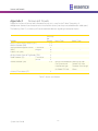
1.3. Content of the Standard Kit Box
The following Table 1 details the content of the Kit Box.
Note: Following description of the Kit Box content refers to the standard kit. Other
combinations of components included in the kit are possible too.
14
WeR@Home™ System User Guide
Introduction
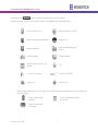
Product
Central Control Unit
(CCU) – Essence
ES8000CP
Description
The WeR@Home™ Central Control Unit. Sometimes referred
to as Control Panel (CP). Manage and communicate with
system peripherals and the Cloud/Servers which provide the
data to the different user applications. Generates notifications
and source data streaming.
It features:
n Users’ remote access for control and management via
Apple’s iOS and Google’s Android™ based
smartphones/tablets and web application software.
n Optional 3G (850/900/1800/1900MHz) modem.
n Automatic APN setting.
n Streaming of data to designated devices (smartphone,
PC, etc.).
n Supports large variety of peripherals and up to 32 Users
(including 2 Master Users).
n Long term battery backup.
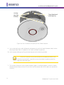
Motion Indoor
Photo Detector
(IPD) – Essence
ES800IPD
A peripheral device combining Passive Infra-Red (PIR) motion
detector along with image capturing camera. Referred to as
the system’s Camera. It features:
n Security/Comfort motion detected images streaming
to smartphone/web applications.
n Compress/Encrypt data with Essence’s proprietary
ECOP protocol.
n Relays stream to the WeR@Home™ servers, via the
Cloud for distribution to designated devices
(smartphone, PC, etc.).
n Multi-zone spherical lens for wide coverage (120o
horizontal, 105o vertical).
n Sealed optics, immune to light, insects, and (optional)
pets, for reduced false alarms.
n Walk-through test mode.
System User Guide
15
Introduction
Product
Motion Detector
(PIR) – Essence
ES800PIR
Description
A Passive Infra-Red (PIR) Motion Detector peripheral device.
It features:
n Sealed optics, immune to light and insects for
reduction of false alarms.
n Multi-zone spherical lens for wide detection coverage
(120o horizontal, 105o vertical).
n Walk-through test mode.
Door/Window
Magnetic Sensor
(MGL) – Essence
ES800MGL
Compact design magnet detector peripheral device, with long
range and easy to install. Referred to as Door/Window Sensor.
It features:
n Dual LED for open/close status indication.
n Composed of a lightweight detector and a magnet.
Indoor Siren (SRN)
– Essence
ES800SRN
A wireless Siren peripheral device, powerful and batteryoperated.
It features:
n Emits loud and powerful siren of up to 95dB with
adjustable volume control.
n Emits sound for 90 seconds upon intrusion.
n Dual purpose as a siren and doorbell.
Remote Control
Unit (RCU) –
Essence ES800KF
A Bi-directional, ultra-compact, Remote Control Unit. Also
referred to as Key Fob (KF). A peripheral device serving as the
WeR@Home™ system Key Fob as well as personal SOS alarm
(panic) button.
It features:
n 5-button interface for setting Full, Day, Night
arm/disarm.
n Status key/LED indication of system status.
n Remote deactivation in case of loss or theft.
n Protection against inadvertent press.
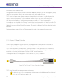
LAN Cable
16
Local Area Network (LAN) cable (Category 5).
A twisted pair cable for carrying the wired data communication
signals. This type of cable is mostly used in structured cabling
for computer networks such as Ethernet. The cable is used for
connecting the CCU to an Internet port via Switch, Hub, etc.).
WeR@Home™ System User Guide
Introduction
Product
Power Adapter
Description
Universal Switching Power Supply converting the mains voltage
into DC power required for the CCU. The adapter include
electrical cord with mini-USB™-like connector providing the
CCU with the power required for proper operation.
Square Battery Pack
– Essence
MCBT05001
The 3.7VDC, 1400mAh Lithium Polymer rechargeable battery is
the backup power source for the CCU in case of mains power
shortage.
Coin Battery
Provides power to the Remote Control Unit (KF).
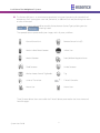
Table 1: WeR@Home™ Box Content
The above items, along with the Shortform User Guide comprise the complete content of the box.
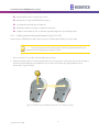
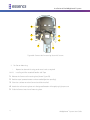
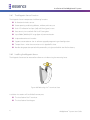
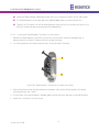
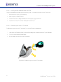
Remote Control Unit (KF)
Motion
Detector
(PIR)
Siren (SRN)
Camera (IPD)
Central
Control
Unit (CCU)
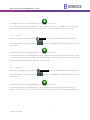
Door/Window Sensor (MGL)
Figure 1: Components Setup in the Box
Note: The LAN cable, Power Adapter and the batteries are packed and stored under
the box inner (black) separator.
System User Guide
17
Introduction
Additional devices may be purchased from local distributors as required. These are described in paragraph 1.4
and Table 2 below.
1.4. Other Available Devices
The system may be expanded with accordance to the premises’ structure and protection methods, by
purchasing additional components (up to the system’s limits detailed in paragraph 3.15 below).
Such additional components may include components from the basic kit (described in the above Table 1) or
other available components, built to serve special purposes, which are described in Table 2 below:
Product
Wireless Access
Control Tag Reader
(TR5) – Essence
ES800TR5 and Tag
(TAG) – ES800TAG
Description
The Wireless Access Control Tag Reader is an access control
peripheral device. The tags are the access keys.
It features:
n An intuitive user-friendly human interface.
n Provides command options to ARM, DISARM, partial
ARM, SOS alarm and pending indoor or outdoor
installation – doorbell or status functions.
n Remote deactivation of tags in case of loss/theft (via
Smartphone or web access).
n Wall Mount – Double sided tape or Screws.
n Uses three standard AA-size Alkaline batteries.
n Long operation period (up to 36 months).
n Tamper Alarm – when detached from wall.
Flood Detector (FL)
– Essence ES800FL
The Flood Detector is a water outpouring early warning
peripheral device.
It features:
n Alarm upon water leakage.
n The alarm is triggered upon water running through
the detection element.
n Fastened to the wall/frame by double-sided tape or
optional screws.
18
WeR@Home™ System User Guide
Introduction
Product
Smoke Detector
(SK2) – Essence
ES800SK2
Description
The Smoke Detector is a stand-alone fire early warning
peripheral device.
It features:
n Tri-color LED for visual indication.
n Emits loud alarm sound of 85dB from 3 m.
n The Smoke Detector is fully operational even if the
CCU is not.
n Tamper Alarm – when detached from its base.
n Long operation life.
n Uses three (3) standard AA-size Alkaline batteries.
Universal
Transmitter (UT) –
Essence ES800UT
The Universal Device is a peripheral device enabling legacy,
hard-wired devices interface onto the WeR@Home™ system.
It features:
n Dual LED for visual status indication.
n Single element – a lightweight RF transmitter with 30
cm double-isolated two-conductor cable.
n Long operation life.
n Uses a single standard AA-size Alkaline battery.
Z-Wave® Controller
(ZWD) – Essence
ES800ZWD
The Z-Wave® Controller is a peripheral controller device
enabling integration of Z-Wave® approved Smart Home
devices (i.e. Door Lock, Light Switch/Dimmer, etc.) onto the
WeR@Home™ system.
It features:
n Single element.
n Long operation life.
Table 2: Other Available Devices
System User Guide
19
System Theory
2. System Theory
The WeR@Home™ system transforms mobile smartphones and tablets, as well as personal computers (PC)
into powerful remote control devices that help increase safety and enhance the quality of life of families. All
system components communicate with the Central Control Unit and the CCU communicates with system
servers via the cloud.
The system is based on a modular structure that is flexible in its expansion capabilities – additional devices
may be added to the system as needed.
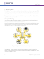
2.1. System Topology
The system consists of the main control component – the Central Control Unit, and sensors/detectors
covering all security aspects and communication components.
It features a comprehensive and expandable sensor/detectors array that provides the flexibility to create an
ideal solution for every Small Office/Home Office (SOHO). Users can add safety and security accessories,
such as additional Cameras, for better protection and monitoring.
Figure 2: WeR@Home™ Home Area Network Components
The WeR@Home™ wireless technology is based on Essence's proprietary Enhanced Controlled Open
Protocol (ECOP), a complete, end-to-end proprietary protocol used throughout the WeR@Home™ system.
See details in paragraph 2.3.1 below.
20
WeR@Home™ System User Guide
System Theory
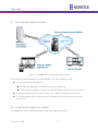
2.2. The Complete System Overview
Figure 3: The WeR@Home™ Cloud Computing Network
The installed system communicates via the cloud platform utilizing the following tools:
n User interface software applications:
˜ Web software application running over the Internet and a PC, or
˜ Mobile software application running over GPRS/EDGE cellular network with a smartphone.
n It may communicate with the server via Internet or via GPRS/EDGE cellular channels, and
n The Service Provider utilizes Internet for communication with the server and all of the Central
Control Units.
2.3. Unique Technologies Incorporated
The WeR@Home™ system incorporates some unique technologies and features:
System User Guide
21
System Theory
2.3.1
Enhanced Controlled Open Protocol
The WeR@Home™ products intercommunicate with the Central Control Unit (CCU) within the HAN (Home
Area Network) using Essence proprietary Enhanced Controlled Open Protocol (ECOP) protocol. The
WeR@Home™ CCU serves as the gateway between the HAN and the GSM/GPRS or Internet network.
n Between home sensors and home control units (ECOP-R).
n For external networks (control unit to the world).
n ECOP-X – The XML representation of the ECOP protocol.
Several types of clients (Web Server, iPhone, Windows Mobile, etc.) parse the ECOP protocol.
The ECOP-N protocol is serialized to a standard XML and is transferred to any kind of client (a distinct ECOPN protocol parser is not needed for each kind of client).
For details of the RF implementation of the ECOP protocol, please refer to paragraph 2.3.2. below.
2.3.2 WeR@Home™ RF Technology
2.3.2.1
Radio Interface Information
The WeR@Home™ system works in a star topology where the Central Control Unit acts as the coordinator,
controlling all other sensors and peripherals.
License-free Band Disturbance
Data is sent over the air utilizing the WeR@Home™ proprietary RF protocol (ECOP) in IEEE 802.15.4 standard
based on the 2.4 GHz ISM band.
n Gateway (GW) uses a band pass filter for out-of-band noise suppression.
n In-band noise is compliant with EN-300-440.
n Inter-systems disturbance – each system uses a specific, 32bits, system identifier and filters nonconforming packets.
Power and Sensitivity
WeR@Home™ systems transmit with maximum allowed power according to standard EN 300 –440 (Europe),
FCC CFR47 Part 15.
Pending the device, power and sensitivity are divided into two (2) main categories:
22
WeR@Home™ System User Guide
System Theory
Sensitivity
Power
-103 dBm (sensors)
14 dBm
-103 dBm (Central Control Unit)
20 dBm
Channels, Bandwidth and Polling
n Using ECOP protocol, the WeR@Home™ system utilizes between 1 to 16 channels.
n The channel bandwidth is 5MHz.
n The WeR@Home™ systems use Beacon-enabled network intervals, about 100ms for quick response
time.
n Modulation type: QPSK, 8 chips DSSS
n Baud rate: 250KBPS
Low Energy Consumption
ECOP protocol is an externally low-power RF protocol based on 16 years of experience in battery-operated
devices. For example, the system uses a mechanism that significantly reduces listening time (one of the major
drains on battery life).
2.3.3 Remote Software Update
The WeR@Home™ system and its components are being constantly upgraded with regards to the software
embedded into them and with regards to their service software packages.
There is no need for any user involvement in these upgrades as these are overall procedures automatically
activated by the Service Provider.
2.3.4 WeR@Home™ Cloud Services
The servers of the WeR@Home™ cloud services are the central applicative abstract unit designed for high
availability, scalability, robustness, geo-redundancy and security.
The WeR@Home™ Infrastructure is designed to support millions of concurrent users over multiple client
platforms (web application, mobile smartphone and tablets applications, mobile phones via SMS, and 3rd
parties consumer data) on various supported protocols (HTTP, SOAP, JSON, REST, TCP).
WeR@Home™ Cloud Services concentrate and encapsulate the entire communication and logic, allowing
users to easily install and enjoy a simplified world of seamless communication between them, their homes
and their mobile/web devices.
System User Guide
23
System Theory
Operators can exercise full real-time control over all system functions, overview the full picture regarding
customer usage, analyze usage patterns and preferences and customize services and activation for each
account.
The WeR@Home™ Cloud Services are based on a few fundamental building blocks, like:
n Asynchronous messaging mechanism.
n Control the devices’ communication layer.
n Account management.
n Account activation/deactivation/suspension, user preferences.
n Monitoring System – Logging, Tracing, Monitoring and Audit.
n Message handling and events logic in addition to rules engine.
n Archive mechanism.
n Protocol adapters and services.
n Composition of ECOP-X protocol.
n Video services.
n Live streaming services.
n Video history analysis.
n System for remote firmware update.
n System for OTA mobile software updates cache distribution custom adaptation.
n 3rd-party application adaptations.
2.3.4.1
WeR@Home™ Web Server
The WeR@Home™ Web Server is the set of services within the WeR@Home™ cloud designed to:
n Allow WeR@Home™ security and Home Automation web application for end users.
n Allow the end user to receive full control over his home, including live and archived images ondemand.
n Allow the operator/service provider to fully control account services, view real time usage statistics
and analyze usage patterns and preferences.
24
WeR@Home™ System User Guide
System Theory
The applications are high-end Rich Internet Applications (RIA), scalable and designed for a smooth user
experience while implementing push mechanisms for seamless client/server communication.
2.3.4.2
Information Consumption Services
The WeR@Home™ system enables access to a special web service layer especially designed for consumer data
such as mobile operators, independent central monitoring stations and other types of 3rd-party organizations
that can benefit from large amounts of mobile/web data and statistics related to system usage.
2.3.4.3
WeR@Home™ Media Services
n The WeR@Home™ System provides real-time continuous-like images supporting monitoring and
security usage.
n The system can handle on-demand requests for images.
n The system can also generate an automatic image request when the home is armed. If an alarm is
triggered, the system stores the images captured by the Camera to be sent upon demand to the
User.
n The system can store the media data on its servers for future access.
n Media data is archived, cached and optimized for best performance.
2.3.4.4
WeR@Home™ SMS Services
The WeR@Home™ system supports handsets from all major handset manufacturers, which typically use
common industry protocols and APIs (HTTP, SOAP, etc.).
2.3.4.5
WeR@Home™ Database
The WeR@Home™ system stores all data that is passed through the system. The data is archived for future use
and analysis. Stored data includes:
n Video events
n Alarms
n Event history (alarms, user activity, etc.)
n Logs of all commands and actions performed by any user
2.3.4.6
WeR@Home™ Analysis Service
The WeR@Home™ analysis service system is designed to provide business intelligence, data mining and
analysis for the operator and other consumer data.
System User Guide
25
System Theory
This page was intentionally left blank
26
WeR@Home™ System User Guide
Installation of the WeR@Home™ System
3. Installation of the WeR@Home™ System
3.1.
Prerequisites
Prior to the installation and setup of the WeR@Home™ system, the following items need to be prepared:
n This document is best read with Adobe Acrobat Reader® version 10.0 (or higher), available for free
download at: http://get.adobe.com/reader/.
An electronic format (PDF) version of this manual is available, for free download, at:
http://www.essence-grp.com/pages/WeR/WeRFullUserGuide.
n AA-size Alkaline batteries for the kit components (10 for the standard kit).
Notes: More batteries might be needed in case additional components were
purchased.
Special batteries: the Central Control Unit’s backup battery and the Remote Control
Unit’s coin-battery are included in the kit.
n A personal computer (PC) with internet access and up-to-date browser application software
(Microsoft™ Internet Explorer® 7 or higher, Firefox® 4 or higher, Google’s Chrome™ browser).
n The Microsoft® Silverlight™ web application framework should also be installed on the PC. It is available
for free download from: http://silverlight.net.
n The Service Provider’s web server address for the WeR@Home™ Web Application software (provided
by the WeR@Home™ distributor/Service Provider).
n If cellular communication is to be used – a SIM-card provided by the distributor or purchased from a
Service Provider.
Notes: Distributor (or Service Provider) of the SIM-card should also provide a 4-digit
APN code for mobile access. In special cases more APN data (see details on page 40)
might be needed.
System User Guide
27
Installation of the WeR@Home™ System
n A smartphone (optional) for remote system management.
n A small screwdriver.
n The Central Control Unit’s identification serial number should be registered prior to the installation
process.
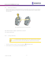
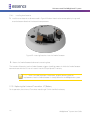
n Stickers with the serial number can be found inside the battery/SIM-card cavity and under the
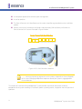
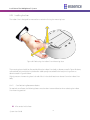
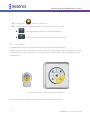
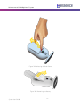
Central Control Unit’s base as illustrated in Figure 4 below.
Figure 4: CCU Serial Number Locations
Note: You may also want to register this serial number in Appendix H Owner’s Records
of this User Guide (page 290) where important data of your system is aggregated for
future reference.
This chapter of Installation of the WeR@Home™ System provides information about each and every
component of the system including its installation, power-up, configuration, integration into the system and
operation.
28
WeR@Home™ System User Guide
Installation of the WeR@Home™ System
It is arranged in the exact same sequence the system needs to be built-up, including the steps of software
installation and registration. Therefore, it is advised to follow this sequence to ensure properly functioning
system.
The WeR@Home™ system is based on independent components described below.
The order of presenting these components is the recommended order of their installation.
Note: Except for the Central Control Unit, not all the below-mentioned components
must be installed for a functional alarm system.
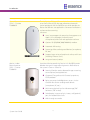
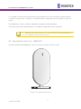
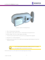
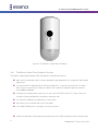
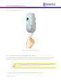
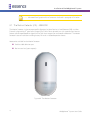
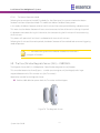
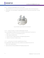
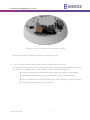
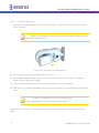
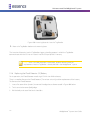
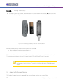
3.2. The Central Control Unit – ES8000CP
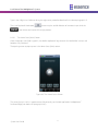
The center-piece of the WeR@Home™ system is the Central Control Unit (CCU or CP).
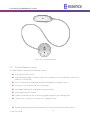
Figure 5: The Central Control Unit
System User Guide
29
Installation of the WeR@Home™ System
It is a two-way, wireless Central Control Unit comprising the main element of the WeR@Home™ system.
3.2.1
The Central Control Unit Function
The Central Control Unit (CCU) is responsible for wireless communication with the array of WeR@Home™
sensors/detectors, remote access and interface devices internally (within the premises), through the RF
communication channel, as well as communications with the external cloud computing services system,
through the Internet or cellular channels.
The CCU incorporates the following functions:
n Two-way secured communications (AES encrypted) with the WeR@Home™ system's peripherals.
n Plug-and-Play Internet (IP) connectivity.
n Optional, built-in GSM/GPRS/EDGE quad-band (850/900/1800/1900MHz) modem.
n Supporting transfer of high quality, high resolution, color pictures.
n Traffic Usage – Simple Event/Command: 200-300 Bytes (text), Streaming Event: 200-250 Kbytes (25
Frames).
n Supports automatic over-the-air software upgrade programming and configuration.
n Rechargeable backup battery.
3.2.2 Installing the Central Control Unit
As mentioned in the above paragraph 2.3.3, prior to the installation of the CCU the following items must be
prepared:
n The CCU’s backup battery.
n A PC connected to the Internet and running browser application software.
n The LAN cable (in case the Internet is to be used as external CCU communication channel).
n The SIM-card provided by the Service Provider (in case the CCU is to be communicating via the
cellular channel) with its 4-digit APN code (other APN data might be required too, see details on
page 40).
n A smartphone (optional).
Registration of the CCU’s serial number (see page 28) should also be completed.
30
WeR@Home™ System User Guide
Installation of the WeR@Home™ System
3.2.2.1
CCU Positioning Recommendations
The CCU should be installed on:
n A flat surface.
n In a central home/office location with:
˜ Unshielded adequate cellular coverage (if cellular communication is to be used).
˜ Close to an Internet connection outlet (modem/router connection, if Internet communication
is to be used).
The CCU must be activated and the system must be registered with the Service Provider (or the distributer) to
enable its proper operation.
The following need to be executed for the setup and activation of the CCU:
1.
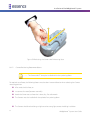
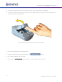
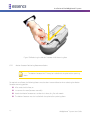
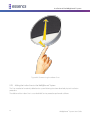
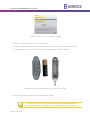
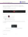
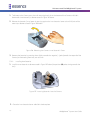
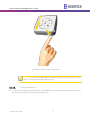
Remove the back cover of the CCU to reveal the battery/SIM-card compartment.
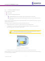
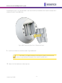
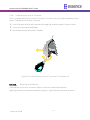
2. In case cellular is intended to be used for external communication – insert the SIM-card, with its
contacts facing down, as illustrated in Figure 6 below.
Note: Refer to the graphic representation of the SIM-card engraved onto the plastic
bottom of the cavity, next to the card’s designated location.
Figure 6: Insertion of the SIM-card
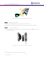
3. In case the Internet is intend to be used as the primary external communication channel:
Plug the LAN cable into the RJ45 socket on the back panel of the CCU and its other end into a network socket
(in the Internet router or modem).
System User Guide
31
Installation of the WeR@Home™ System
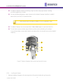
LED 2
LED 1
Figure 7: Insertion of LAN Cable into the CCU Socket
The CCU back panel LAN (RJ45) socket provides two (2) LED status indications, active in accordance with the
IEEE 802.3u standard, as a convenient means of determining the mode of operation of the network:
i.
LED1 (Green) is the Link Activity LED.
4. It will lit steady once the network transceiver detects a valid link and will blink upon link activity
(transmit/receive).
ii.
LED2 (Amber) is the Link Speed LED.
5. It will turn ON once the detected link speed is 100Mbit/Sec and will turn OFF once the detected link
speed is 10Mbit/Sec. A blinking LED2 indicates communication collision.
6. If there is no Internet connection available or the LAN cable is not connected, the SIM-card will be
used as the primary connection channel between the WeR@Home™ system and the WeR@Home™
server.
Note: If both the SIM-card and the LAN cable are installed, the Internet will be the
primary communication method and the cellular channel will be used for backup.
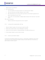
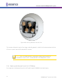
7. Insert the backup battery into the battery cavity, above the SIM-card.
Note: Battery’s label should be facing up and the battery’s contacts – aiming towards
the base of the CCU.
32
WeR@Home™ System User Guide
Installation of the WeR@Home™ System
Figure 8: Insertion of the Backup Battery
8. Return the battery cover back to place.
9. Plug the Power Supply's cable into the mini-USB™ connector on the back of the CCU.
10. Plug the adapter’s cube into an electric power outlet socket.
11. The LED on the front panel of the Central Control Unit should light with orange color.
12. Place the CCU in its designated location.
13. Wait for the CCU’s front panel LED to switch from orange to green color before continuing to subparagraph 3.2.3 below.
Notes: The LED switching from orange to green indicates that the CCU is properly
active. It takes approximately 5 minutes for the LED to switch.
The Central Control Unit is now ready for the next step of registration and setup.
System User Guide
33
Installation of the WeR@Home™ System
Note: The initial registration is a web-only procedure and therefore could be exercised
utilizing the Web Application only (cannot be done with the Mobile Application).
3.2.3 Activating the Central Control Unit
Notes: This paragraph details the initial registration process of the system, utilizing the
WeR@Home™ Web Application software. It is a one-time procedure exercised as part of
the activation of the system’s Central Control Unit. The WeR@Home™ Web Application
is a comprehensive software package dealing not only with this initial registration
procedure but with all aspects of administrating the WeR@Home™ system (Status
reports, peripheral devices’ add/remove and setup, events history, etc.). It is, therefore,
recommended to read paragraph 3.3 The WeR@Home™ Web Application below prior
to the activation of the CCU.
Activation of the CCU begins with registration of the WeR@Home™ system with the Service Provider’s web
server. Besides introducing the WeR@Home™ system to the server, via the cloud, it also allows the definition
of method of mobile communications.
Note: Typing-in the login information (email address and password) and clicking over
the
button will be the only action required for subsequent logging onto the
™
WeR@Home Web Application.
The registration procedure is done via the WeR@Home™ Web Application as follows:
1.
Utilizing PC running web browser software, go to the WeR@Home™ Web Application by entering the
Service Providers’ server address.
Note: You may want to create a short-cut link for this address for ease of future access
to the Web Application.
34
WeR@Home™ System User Guide
Installation of the WeR@Home™ System
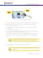
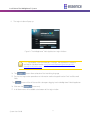
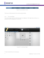
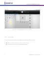
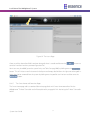
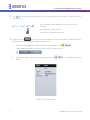
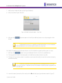
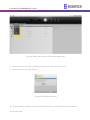
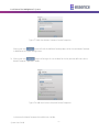
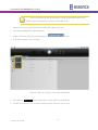
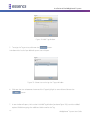
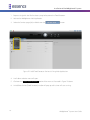
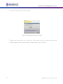
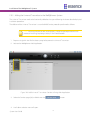
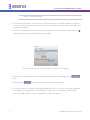
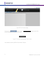
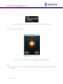
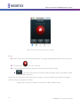
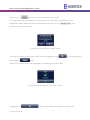
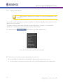
2. The Login window will pop-up:
Figure 9: The WeR@Home™ Web Application Login Window
Note: If prompted, install the Microsoft® Silverlight™ web application framework
available for free download at: http://www.microsoft.com/getsilverlight/GetStarted/Install/Default.aspx.
14. The
button allows selection of the interfacing language.
15. For the initial registration procedure no information need to be typed into the Email and Password
fields.
The
button will be will be used for subsequent logging into the WeR@Home™ Web Application.
16. Click over the
button only.
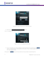
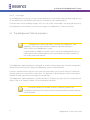
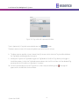
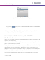
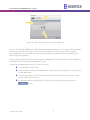
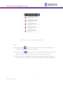
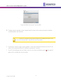
17. A roll-down menu will be added at the bottom of the Login window:
System User Guide
35
Installation of the WeR@Home™ System
Figure 10: The Login Window with the Roll-down Menu
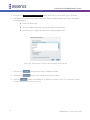
18. Click over the _Go to first time registration page >>_ option.
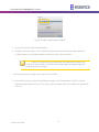
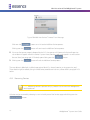
The First Time Registration (Step 1 of 2) window appears:
Figure 11: CCU First Time Registration Window
19. Type-in the 8-digits serial number recorded on page 28 (and Appendix H) and click over the
button. The Web Application software performs, at this point in time, a validation procedure to ensure
the number typed is correct.
Clicking over the
36
button will take you back to the Login window (see above Figure 10).
WeR@Home™ System User Guide
Installation of the WeR@Home™ System
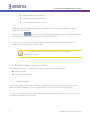
In case the CCU was previously incompletely registered and this procedure started before the front CCU’s
LED switched to green; a Panel Not Connected error message will pop-up:
Figure 12: Panel Not Connected Error Message
In case this serial number was already registered with the system; an Existing Serial Number error message will
pop-up:
Figure 13: Existing Serial Number Error Message
20. In case the serial number typed was invalid; an Invalid Serial error message will pop-up:
Figure 14: Invalid Serial Error Message
21. In all the above error cases, clicking over the
(see above Figure 10).
button will take you back to the Login window
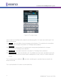
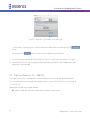
22. In case the number typed is valid, the First Time Registration (Step 2 of 2) window will pop-up:
System User Guide
37
Installation of the WeR@Home™ System
Figure 15: First Time Registration Step 2 Window
Note: You may want to record the following registration details to Appendix H
Owner’s Records of this guide (page 290) where important data of your system is
gathered for future reference.
23. Type-in your personal details as follows:
i.
_Email_ – Address where system’s messages and notifications will be sent to via email.
ii.
This address will also be used for subsequent login (see above Figure 9).
iii.
_Password_ – Required for safe login.
Note: The login password is case sensitive and must have a minimum of six (6)
alphanumeric characters.
This password need to be confirmed (re-typed) in the next field – _Confirm Password_.
24. The information provided for the above fields will also be used as key-codes for subsequent accesses
to the Web Application (see above Figure 9).
38
WeR@Home™ System User Guide
Installation of the WeR@Home™ System
i.
_Name_ – The User Name you will be identified with in the system. This is a case-sensitive,
alphanumeric characters’ field.
ii.
_Enter Mobile #_ – Type-in your mobile telephone number.
25. This data is for information records only (not used at this point in time).
26. Use digits only in international telephone number format (for example: 972522728110).
i.
_User Code_ – For the WeR@Home™ Mobile Application to be installed on a later stage on the
smartphone, you are required to initiate a four (4) digits user identification code (an extra
password).
ii.
_TimeZone_ – Select your time-zone from the roll-down menu, to synchronize the system clock
for correct email messages and notifications time-stamps.
Note: The Web Application servers are always set to zero (0) UTC time zone (Zulu
time).
27. Acknowledge your acceptance of the Terms & Conditions of usage for this software by marking the
check-box at the bottom-left side of the window.
A copy of this terms and conditions is attached to this guide as Appendix B End User License Agreement
(EULA).
It is also accessible via the link _Terms & Conditions and the Privacy Policy_.
28. Clicking over the
button terminates the process (upon completion).
Clicking over the
button, throughout the above process, bounces you back to the First Time
Registration Page 1 window (see above Figure 11).
Clicking over the
(see above Figure 10).
button, throughout the above process, bounces you back to the Login window
29. If no error detected during the above procedure of entering the initial registration data, the following
confirmation message will pop-up:
System User Guide
39
Installation of the WeR@Home™ System
Figure 16: Registration Confirmation Message Window
Within a period of approximately 5 minutes, the CCU’s front LED should turn green and the registration
process is concluded.
Notes: If the LED remains orange (does not switch to green), it means that
communication could not be established (verified and registered properly), usually due
to wrong APN data.
Green flashing LED means the CCU is being updated by the Remote Software Upgrade
(RSU) mechanism.
Clicking over the
button will close this message window (but the process of connecting will continue
until completed as indicated by the LED switching to green).
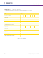
3.2.3.1
Manual Access Point Name Data Registration
In case a problem is encountered during the initial registration procedure, with the Access Point Name (APN)
data; you need to contact the SIM-card’s Cellular Operator/Service Provider and get all of the APN data.
This data need to be manually typed into the registration data fields.
This is done by clicking over the _APN Settings Registration >>_ menu option of the roll-down menu added
to the Login window (see above Figure 10).
Once the _APN Settings Registration >>_ is clicked over, the APN Settings Configuration window pops-up:
40
WeR@Home™ System User Guide
Installation of the WeR@Home™ System
Figure 17: APN Settings Window
Most market available SIM-card’s APN data is pre-programmed into the WeR@Home™ system and being
updated on a regular basis, therefore:
1.
The automatic process executed following the click over the
38) should complete the registration process with no problem.
button (see line-item 23 on page
In case the process does not complete properly (the LED did not turn green):
Note: A short-form explanation regarding this process is also available online by
clicking over the button.
i.
Call your cellular Service Provider and obtain all APN data (APN name, APN user and APN password).
Note: You may want to record the APN data to Appendix H of this User Guide where
important data of your system is gathered for future reference.
ii.
Select the _Country_ and _Operator_ (Cellular Service Provider) from the roll-down menus in the
APN Settings Configuration window (see above Figure 17).
System User Guide
41
Installation of the WeR@Home™ System
iii.
Manually type-in all the APN data retrieved from the Cellular Service Provider.
iv.
In the _SIM card of the Panel:_ field, type-in the international cellular telephone number of the
SIM-card (digits only, no prefix, for example: 972522728110) and the CCU’s serial number (see page
28 and Appendix H) and click over the
button.
v.
Wait for the front panel LED to turn green (may take up to 15 minutes).
In case the manual entry of APN data is done for a CCU which was already registered (i.e. upon replacing a
faulty SIM-card), the APN Settings Configuration window shown in the above Figure 17 will pop-up with the
CCU’s Serial Number already typed-in (but greyed-out) as illustrated in Figure 18 below:
Figure 18: APN Settings Window for a Registered CCU
2. Once the system is registered, it is recommended to add Users before proceeding to the next step of
installation. See details in the below paragraph 3.3.6.4.
3.3. The WeR@Home™ Web Application
The WeR@Home™ Web Application is classic cloud-computing software application based on the latest RIA
(Rich Internet Application) technologies and utilizes Microsoft® Silverlight® technology. It provides smooth,
fast and responsive experience along a set of tools for home security and management.
42
WeR@Home™ System User Guide
Installation of the WeR@Home™ System
The run-time environment for Silverlight® is available as a plug-in for most web browsers based on the
Microsoft® Windows® OS (Operating System). It is available for free download from:
http://www.microsoft.com/getsilverlight/Get-Started/Install/Default.aspx.
Note: The previous paragraph already dealt with the Web Application, with respect to
the first-time system registration only.
It was a one-time procedure exercised as an action item within the process of the
activation/registration of the system’s CCU.
This paragraph details all other aspects of the WeR@Home™ Web Application.
3.3.1
The Web Application Function
The Web Application provides the user with access to the following system functions:
n Home monitoring, safety, security and smart home management.
n Self-installation and activation via the web.
n Dashboard page – Presents:
˜ System Status,
˜ System Activation,
˜ Device Overviews,
˜ Recent Events,
˜ Look-in via Camera.
n Devices page – Manages system devices.
n History page – Allows investigation of recent events including video as well as filtering of the event
history log.
n Users page – Manage Users (Master User, Standard User).
n Central Control Unit Signal Strength Indicator – Displays the GSM signal strength (for Central
Control Units with a SIM-card).
n APN Activation – Automatic APN activation. Available for any SIM-card supporting SMS and data
transfer.
System User Guide
43
Installation of the WeR@Home™ System
n Notifications – Tamper, Low battery, Connection Lost, power failure/restore.
n Chime – Optional siren feature.
n Multilingual support.
3.3.2 Activating the Web Application
Being a classic cloud-computing application, the WeR@Home™ Web Application requires only a PC with an
Internet browser to access and use.
There is no need to download and/or install any software.
3.3.2.1
Prerequisites
The following items need to be prepared before installing the WeR@Home™ Web Application:
n A personal computer (PC) with internet access and up-to-date browser application software (Internet
Explorer® 7 or higher, or Firefox® 4 or higher, or Chrome™ browser).
n The Microsoft® Silverlight™ web application framework should also be installed on the PC. It is available
for free download and installation at: http://www.microsoft.com/getsilverlight/GetStarted/Install/Default.aspx.
n The Service Provider’s web address (URL) for the WeR@Home™ Web Application software.
Note: You may want to create a short-cut link for this address for future ease of access
to the Web Application.
n A smartphone (optional) for remote system management.
44
WeR@Home™ System User Guide
Installation of the WeR@Home™ System
3.3.3
The Web Application Display Structure
The screen of the WeR@Home™ Web Application is divided into functional areas where:
1
Tool Bar – presents some basic control tools for the WeR@Home™ Web Application.
2
Status/Activation Bar – For the WeR@Home™ system’s status display and setting of mode of
operation.
3
Displayed Data Selection Tabs – used to select the type of information displayed.
4
Data – different data types selected by the tabs, for display and manipulation.
1
2
3
4
Figure 19: The Web Application Display
System User Guide
45
Installation of the WeR@Home™ System
3.3.4 The Tool Bar
The Tool bar provides access to the global most common Web Application setting tools:
Figure 20: The Tool Bar
n The
icon provides information regarding the strength of the CCU’s cellular signal. It could display:
or
or
or
or
Signal strength meter indicating the CCU’s cellular signal
strength.
No SIM-card installed in the CCU.
Cellular channel communication lost.
n The
icon provides information regarding the charge capacity of the CCU backup battery. It
could display:
Battery dead
Battery critical
Battery low
Battery normal
Battery full
n The
46
button launches the Settings Configuration window:
WeR@Home™ System User Guide
Installation of the WeR@Home™ System
Figure 21: The Settings Configuration Window
This window is a sub-set of the initial registration procedure (see paragraph 3.2.3. above) which allows
(by tab selection):
t Re-setting of the Time Zone defined in the initial registration procedure (see page 39) by
selecting it from the roll-down selection menu which opens upon clicking over the
button.
Any change made to the previously defined Time Zone need to be saved by clicking over
the
button.
Termination of this activity is done by clicking over the
button.
t Manual entry of APN data; a similar process to the one described in the above subparagraph 3.2.3.1.
Note that the CCU’s _Serial #_ appears grey and cannot be edited, since we are dealing, at this point in time,
with a formerly registered system.
The
button brings up a quick help file for APN data entry.
Following the entry of all APN data, there is a need to click over the
the data onto the CCU’s memory.
Termination of this process is done by clicking over the
System User Guide
47
button to transfer
button.
Installation of the WeR@Home™ System
Figure 22: Manual Entry of APN Data Window
n The
n The
3.3.5
button opens this WeR@Home™ System User Guide document.
button logs out of the Web Application and terminates its operation.
The Status/Activation Bar
The Status/Activation bar provides, at a glance, real-time information about the system status as well as
enabling basic system arming commands.
Figure 23: The Status/Activation Bar
Clicking over any of the three
arming buttons will trigger the system into the operation mode called for
(Full Arm, Day Arm or Night Arm).
The system status is reflected by the image and color of the central icon as follows:
48
WeR@Home™ System User Guide
Installation of the WeR@Home™ System
System Disarmed
System (fully) Armed
(grey)
(green)
Burglary Alarm
System Day Armed
(red)
(green)
Safety Hazard
System Night Armed
(yellow)
(green)
The text messages to the left of this icon word-out the meaning of the image on display.
3.3.6 The Data Window
The data window allows in-depth system setup, monitoring and control. The type of data to be displayed and
dealt with is presented over four (4) or six (6) pages (pending the inclusion of a Z-Wave® Controller), selected
by a tab bar with the following four (4) basic tab options:
Figure 24: Data Window 4-Tab Bar
In case a Z-Wave® controller (a Smart Home application) is installed, the basic four (4) tab bar is expanded to
include two (2) more tabs dealing with the setup of Z-Wave® devices and their scenarios of operation.
System User Guide
49
Installation of the WeR@Home™ System
Figure 25: Data Window 6-Tab Bar
These cases will be discussed within the relevant paragraphs below.
3.3.6.1
The Dashboard Page
The Dashboard page is the main (and default) page of the WeR@Home™ Web Application providing an at-aglance overview of the WeR@Home™ system status.
Figure 26: The Dashboard Page
This data window divides into three (3) panes:
50
WeR@Home™ System User Guide
Installation of the WeR@Home™ System
n The Devices (left) pane – an overview pane graphically (using icons) presenting all system defined
components, their system given name and, sometimes, an additional sub-icon presenting their event
or status information.
System status presentation could be sorted by Device Name or Device Type by clicking over the
/
switching button.
The reported items are presented by icon images, within all panes, as follows:
Central Control Unit
Remote Control Unit (KF)
Motion Indoor Photo Detector
Indoor Siren
Motion Detector
Door/Window Magnetic Sensor
Flood Detector
Smoke Detector
Wireless Access Control Tag Reader
Tag
Universal Transmitter
Z-Wave® Controller
Master User
Normal User
Three (3) more devices’ icons are used for the Z-Wave® devices presented on the Smart Home and
Scenarios pages:
System User Guide
51
Installation of the WeR@Home™ System
Z-Wave® device type Doorlock
Z-Wave® device type Switch or
Dimmer
Z-Wave® device type Thermostat
These icons may:
˜ Change their color in accordance with their reported event/status (i.e. turn red upon tampered
event).
˜ Presented with colored items:
Door/Window Magnetic Sensor
CLOSED
Door/Window Magnetic Sensor
OPENED
Power failure
Power restored
Universal Transmitter CLOSED
Universal Transmitter OPENED
˜ Presented with (or by) additional sub-icon symbolizing the status or event. These additional
event/status sub-icons could be:
52
APN failure
APN restored
Broken (Connection Lost)
Connection restored
Low battery
Low Connection
Battery FULL event
Battery NORMAL event
Battery LOW event
Battery CRITICAL event
Battery DEAD event
Warning (i.e. tamper, power
failure, etc.)
WeR@Home™ System User Guide
Installation of the WeR@Home™ System
n The Recent Events (right) pane – a detailed pane graphically (utilizing icons) presenting a log of all
system defined components which participated in the last events. Data presented include time
stamp (date and time) of the event and some additional text explaining the nature of the event. The
presentation icons are similar to the above mentioned Devices Pane icons.
n The Cameras (middle) pane (sub divided into upper and lower sub-panes) is used for presentation of
the images captured by the Camera devices of the system. The lower part presents a graphical
(utilizing icons) list of all system defined Cameras with their system name. Clicking over one of them
will present its captured images in the upper sub-pane. Clicking over the
button will run them in
video-like mode.
In cases of special interfaces or applications (i.e. the Z-Wave® Controller), not only that the Tab bar will be
expanded to include two (2) additional Smart Home tabs, but the Dashboard page Devices’ pane will display
an icon presenting the interface/application. For example, in the case of a Z-Wave® Controller, the following
icon will present the Z-Wave® Controller:
Figure 27: The Z-Wave® Controller Icon
And the Dashboard would look like:
System User Guide
53
Installation of the WeR@Home™ System
Figure 28: The Dashboard Page with Z-Wave® Controller
3.3.6.2
The Devices Page
The Devices page provides an overview of the WeR@Home™ system defined devices and allows:
n Addition or removal of Devices to the system (by Master User only).
n Editing (by Master User only) of their operational characteristics.
54
WeR@Home™ System User Guide
Installation of the WeR@Home™ System
Figure 29: The Devices Page
This page divides into two (2) panes:
n The Devices (left) pane – an overview pane presenting all system defined components, their icon
image (for type), their system given name/location and their current status including icon indication
of their signal strength and battery level.
n Details of operational characteristics of the highlighted line-item (device) in the Devices pane are
displayed in the pane to the right – the details pane. These may be edited (by a Master User only).
Any change made to these details must be saved by clicking over the
button.
There is an extension of operational characteristics information for the sensor devices (i.e. IPD, PIR,
MGL etc.) which may be revealed and edited by clicking over the
button.
This button is available only when sensor devices are selected on the left Devices pane.
System User Guide
55
Installation of the WeR@Home™ System
Master User(s) may also add new device(s) to the system by clicking over the
button. A
detailed explanation of such a procedure is provided within every component installation paragraph in this
guide.
Master User(s) may also remove device(s) from the system by selecting a device (line item in the Devices
pane) and clicking over the
button. A detailed explanation of such a procedure is provided
within every component installation paragraph in this guide.
3.3.6.3
The History Page
The History page presents the system log of events.
Figure 30: The History Page
This page divides into two (2) panes in addition to a log-file filter definition tool bar:
56
WeR@Home™ System User Guide
Installation of the WeR@Home™ System
n The Events (left) overview left pane displaying, in sequential order, all recorded system events with:
t Icon images of the items the event relates to,
t Description of the event, and
t A time-stamp (date and time) of the event.
n Above the Events pane there is a History filter definition toolbar enabling definition of filtered data
to be displayed in the Events pane.
Figure 31: The History Filter Toolbar
This toolbar include the following tools to define the filter:
1)
_Date From:_ – defines the date from which the filter will allow pass data for display.
Date is selected by clicking over the
selection of the desired date.
button which opens calendar-like menu for
2) _Date To:_ – defines the last date allowed for the filter to pass data for display. Date is
selected by clicking over the
the desired date.
button which opens calendar-like menu for selection of
3) _Device Name:_ – allowing selection of which Devices will be presented by the filter by
Devices’ system (given) name. The specific Device(s) are selected by clicking over the
button which opens a selection roll-down menu where the desired Device(s) need to be
marked.
4) _Event Type:_ – allows selection of which event type(s) data will be passed by the filter
for display. The specific Event(s) are selected by clicking over the
button which opens
a selection roll-down menu where the desired Event(s) need to be marked.
5) _User Name:_ – allows selection of which of the Users related devices will be passed by
the filter for display. The specific User(s) are selected by clicking over the
button
which opens a selection roll-down menu where the desired User(s) need to be marked.
Once these filter’s criteria are completely defined, applying them to see the filtered results is done by clicking
over the
button.
System User Guide
57
Installation of the WeR@Home™ System
To clear previous filter data – click over the
button.
The characteristics of the highlighted line-item (Event) in the Event pane are presented in the pane to the
right.
3.3.6.4
The Users Page
The Users page provides the system Users’ information.
The window divides into two (2) panes:
t The left overview pane provides the User name and type.
t The right details pane provides all required data of the highlighted User line-item in the
left pane. This data include:
§
The User name.
§
The User Email address (for notifications).
§
The User Profile – Standard or Master.
Notes: Unlike a Standard User, a Master User may modify the system configuration
data, system Users data etc.
Up to two (2) Master Users may be defined in a single system.
Maximum total of 32 Users are supported by a single system.
58
§
The Notification Language.
§
The User Code (four digits) for the Mobile Application.
§
The ability to edit the User’s password.
WeR@Home™ System User Guide
Installation of the WeR@Home™ System
Figure 32: The Users Page
Once any of the above data fields have been changed; there is a need to click over the
store the new data into the system configuration files.
button to
New Users may be added (up to the system limits, see Table 5 on page 190) by clicking over the
button. This will initiate a new line item on the left pane and empty data fields on the right one to be typed-in.
Users may also be removed from the system by clicking over the specific User line item and then over the
button.
3.3.6.5
The Smart Home and Scenarios Pages
The Smart Home page and its associated Scenarios page, deals with Smart Home controllers like the
WeR@Home™ Z-Wave® Controller and will be explained in paragraph 3.14.4. Activating the Z-Wave® Controller
below.
System User Guide
59
Installation of the WeR@Home™ System
3.3.6.6
Other Pages
As the WeR@Home™ system gains more and more applications and interfaces, special purpose pages are (and
will be) added to the Data Window to provide User Interfaces for such special purposes.
The explanations for these additional pages, within this User Guide, are provided in the paragraphs discussing
such applications and interfaces (i.e. the Scenarios page in the WeR@Home™ Z-Wave® Controller).
3.4. The WeR@Home™ Mobile Application
Note: The WeR@Home™ Mobile Application is based on the WeR@Home™ Web
Application and built to allow mobile (smartphones and tablet computers)
administration of the WeR@Home™ system.
Its details below are added at this point in time, since this knowledge could serve as a
helpful tool for the installation process of the system devices by allowing mobility of
the installer around the premises.
The WeR@Home™ Mobile Application is designed for reliability and low latency, top-tier home management
solution for controlling and managing the WeR@Home™ system via mobile devices.
It contains a communication engine ensuring everlasting connectivity to the server and a push-notification
message mechanism in case of alarms and events. The application is designed to consume minimal amount
of power for battery preservation for longer time of operation.
The WeR@Home™ Mobile Application is available for iPhone® iOS operating system (OS) for smartphones and
tablets as well as for Google™ Android™ OS for smartphones and tablets.
Note: Differences between the Android™ and the iOS operating systems and
smartphones might result with some minor dissimilarity between the screens captures
presented below.
60
WeR@Home™ System User Guide
Installation of the WeR@Home™ System
It features the following home management functions:
n Push notifications for triggered events
n System status
n Arm activation (Full Arm, Day Arm, Night Arm)
n Look-in via live imaging
n Events history and filtering of events history
n View GSM signal strength (for CCU model with a SIM-card)
n Multilingual support
n Device statuses
n Smart Home control via Z-Wave® devices (i.e. thermostat, dimmer, doorlock)
3.4.1
Downloading and Installing the WeR@Home™ Mobile Application
The Mobile Application, for both Apple® iPhone® (iOS) and
Android™ users, may be downloaded later from the following
QR-code link:
(or search within Apple’s App Store or Google’s Play for We.R™)
These applications guide the user through all phases of the
identification, installation and registration process.
Once the software is downloaded and the installation process has ended, the following Login screen will popup:
System User Guide
61
Installation of the WeR@Home™ System
Figure 33: The Login Screen
Similar to the First Time Registration procedure (see above page 38), in this screen you need to type-in the
following information:
1. _Email:_ – Your email address for push messages and notifications. This need to be the same address
provided within the above-mentioned First Time Registration procedure.
2. _Password:_ – Your password. This need to be the same password provided within the abovementioned First Time Registration procedure.
3. _User Code:_ –User Code initiated within the above First Time Registration procedure.
4. _IP/Hostname:_ – The Service Provider’s URL. This IP address (or Hostname) is provided to you by the
WeR@Home™ dealer where you purchased the WeR@Home™ system, usually on a sticker attached to
the box.
The last two items has an additional
content of the field.
icon which, by clicking over it, provides help text to explain the
The virtual keyboard on this screen has some special keys:
62
WeR@Home™ System User Guide
Installation of the WeR@Home™ System
Key Name
Icon
Description
Backspace
Used to erase characters.
Uppercase
Used for globally switching the keyboard between upper and lower
case characters.
Numeric
Used for globally switching the keyboard between alphabetic keys
and numeric keys.
Language
Used for globally switching the keyboard character-set between
languages.
COM Shortcut
This is a shortcut key inserting the .COM extension for Email and
IP/Hostname fields.
Go
Once all data is properly typed-in, this key terminates the Login
data entry process and sends the data to the servers.
Table 3: Special Keys on the Login Virtual Keyboard
In addition to the above-mentioned keys, there is another special key, on the top-right end of the screen,
allowing immediate login following entry of all data fields –
.
3.4.2 Limitations of the WeR@Home™ Mobile Application
As mentioned before, the WeR@Home™ Mobile Application is an extension of the Web Application.
But, being a mobile application running over the limited resources of mobile devices and their operating
systems, some of the Web Application’s features had to be omitted.
These are:
n The Mobile Application does not allow settings (adding/modifying) of system Users.
n The Mobile Application does not allow settings (adding/modifying) of system Devices.
In addition, if the WeR@Home™ Mobile Application is installed on multiple mobile devices for a specific User,
the push notifications might not be received by all of them.
System User Guide
63
Installation of the WeR@Home™ System
3.4.3 Using the Mobile Application
The installation of the WeR@Home™ Mobile Application creates, among other things, an icon on the mobile
device’s main screen. Tapping over this icon will activate the WeR@Home™ Mobile Application.
Figure 34: The Mobile Application Icon
If never registered before, the first screen to pop-up is presented in Figure 33 above. The registration need to
be completed (see paragraph 3.4.1 above) prior to the usage of the Mobile Application.
3.4.3.1
The User Code Screen
In case the Mobile Application was properly installed and registered, the first screen to pop-up is:
Figure 35: The User Code Login Screen
64
WeR@Home™ System User Guide
Installation of the WeR@Home™ System
Type-in the 4-digits User Code set during the registration procedure described in the above paragraph 3.4.1.
The virtual keyboard’s backspace
button may be used for deletion of erroneous input while the
button allows termination of the Login process.
3.4.3.2
The Home Status (Main) Screen
Once the correct User Code is typed-in, the Mobile Application logs onto the Service Provider’s servers and
becomes fully functional.
The opening screen to pop-up next is the Home Status (Main) screen:
Figure 36: The Home Status Screen
The Home Status is similar, in appearance and functionality, to the Web Application’s WeR@Home™
Dashboard Page (see above sub-paragraph 3.3.6.1):
System User Guide
65
Installation of the WeR@Home™ System
1. The
icon on the top-left side of the screen is a RF signal strength meter of the CCU’s cellular signal. It
could display:
or
or
or
or
Signal strength meter indicating the CCU’s cellular signal
strength.
No SIM-card installed in the CCU.
Cellular channel communication lost.
2. Tapping over the
button at the top-right side of the screen, will switch the mobile device into
the Settings screen (see Figure 38 below) where you may:
i.
Log out of the WeR@Home™ Mobile Application by tapping over the
ii.
Select temperate display units between Celsius and Fahrenheit with the
.
.
iii.
Bring up the system information page by tapping over the
screen:
. This will open the following
Figure 37: The About Screen
66
WeR@Home™ System User Guide
Installation of the WeR@Home™ System
This page provides the WeR@Home™ Mobile Application software version, the registered User email address
and the CCU (Panel) type.
Tapping over the
iv.
button will switch the screen back to the Settings screen.
View the Service Provider’s servers address (URL) with
Figure 38: The Settings Screen
Upon completion of settings, terminate the session by tapping over the
button.
3. The center piece is similar, in appearance and functionality, to the Web Application’s Status/Activation
Bar (see above paragraph 3.3.5) providing, at a glance, real-time information about the system status as
well as enabling basic system arming commands;
Tapping over any of the three arming buttons (
,
,
operation mode called for (Full Arm, Day Arm or Night Arm), just like the
Status/Activation Bar.
System User Guide
67
) will trigger the system into the
arming buttons in the
Installation of the WeR@Home™ System
Note: Definition of arming modes is set via the WeR@Home™ Web Application only,
utilizing the Devices Page. See paragraph 4.5. Managing Devices below
The system status is reflected by the image and color of the central icon as follows:
System Disarmed
System (fully) Armed
(green)
(grey)
Burglary Alarm
(red)
System Day Armed
(green)
Safety Hazard
(yellow)
System Night Armed
(green)
The text messages, on top of this icon, word-out the meaning of the image on display.
4. The Tab Bar at the bottom of the screen provides similar functionality to the Tab Bar of the WeR@Home™
Web Application allowing quick access to the different display functions (screens) of the WeR@Home™
Mobile Application.
Figure 39: The Home Status Screen Tab Bar
n The Status Tab/screen returns the mobile device’s display to the Home Status (Main) screen (see
68
WeR@Home™ System User Guide
Installation of the WeR@Home™ System
above Figure 36).
n The Video Tab/screen allows comfort (non-alarm triggered, initiated by the User) view of the
environment where the camera is installed.
Tapping over the Video Tab will switch the display to the Take Video screen (see Figure 40 below). This screen
displays all cameras included in your system and the desired camera should be selected out of this list.
Figure 40: The Take Video Screen
To refresh the Available Cameras list – tap over the
button.
Tapping over one of the cameras in the list will select it and will switch the screen into a camera display screen
presenting the view in front of the camera.
The square button at the bottom of this screen is your Play/Pause switch.
Tapping over the
button will terminate the comfort video session and return the display to
the Home Status (Main) screen (see above Figure 36).
System User Guide
69
Installation of the WeR@Home™ System
Figure 41: Comfort View of Camera
n The Devices Tab/screen opens a status screen presenting all system devices and their events/status
icons similar to the Devices Page of the WeR@Home™ Web Application:
Figure 42: Devices Screen
70
WeR@Home™ System User Guide
Installation of the WeR@Home™ System
Tapping over the
button refreshes the content of this status screen.
The devices’ icons are similar to the icons used in the WeR@Home™ Web Application:
Central Control Unit
Remote Control Unit (KF)
Motion Indoor Photo Detector
Indoor Siren
Motion Detector
Door/Window Magnetic
Sensor
Flood Detector
Smoke Detector
Wireless Access Control Tag
Reader
Tag
Universal Transmitter
Z-Wave® Controller
Master User
Normal User
Three (3) more devices’ icons are used for the Z-Wave® devices presented on the Smart Home and
Scenarios pages:
Z-Wave® device type
Doorlock
Z-Wave® device type Switch
or Dimmer
Z-Wave® device type
Thermostat
System User Guide
71
Installation of the WeR@Home™ System
These icons may:
t Change their color in accordance with their reported event/status (i.e. turn red upon
tampered event).
t Presented with colored items:
Door/Window Magnetic
Sensor CLOSED
Door/Window Magnetic
Sensor OPENED
Power failure
Power restored
Universal Transmitter CLOSED
Universal Transmitter OPENED
t Presented with (or by) additional sub-icon symbolizing the status or event. These
additional event/status sub-icons could be:
72
APN failure
APN restored
Broken (Connection Lost)
Connection restored
Low battery
Low Connection
Battery FULL event
Battery NORMAL event
Battery LOW event
Battery CRITICAL event
Battery DEAD event
Warning
WeR@Home™ System User Guide
Installation of the WeR@Home™ System
Note: As mentioned before, the WeR@Home™ Mobile Application allows devices’
status display only and cannot be used for their setup.
n The Smart Home Tab/screen opens a status screen for all system Z-Wave® devices with their
events/status icons similar to the Smart Home Page of the WeR@Home™ Web Application:
Figure 43: Smart Home Screen
Tapping over the
button refreshes the content of this screen.
The devices’ icons are similar to the icons used in the WeR@Home™ Web Application:
Z-Wave® device type
Doorlock
Z-Wave® device type Switch
or Dimmer
Z-Wave® device type
Thermostat
For switch-mode devices (Z-Wave® Switch and Dimmer class), switching the device ON and OFF is possible
System User Guide
73
Installation of the WeR@Home™ System
directly from this screen by tapping over the
button.
For devices which may present more details, an † is added to the right. Tapping over this † will switch the
display into a new screen expanding on the information related to the specific device. For example:
t Expansion screen for Dimmer class devices:
Figure 44: Dimmer Class Device Expansion Screen
The
button provides device ON/OFF switching function (similar to the above mentioned
button).
The
slide control provides analog control of the dimmer level.
Once all features are set, going back to the Smart Home screen is done by tapping over the
button.
74
WeR@Home™ System User Guide
Installation of the WeR@Home™ System
t Expansion screen for Thermostat class devices:
Figure 45: Thermostat Class Device Expansion Screen
The
button provides device ON/OFF switching function (similar to the above
mentioned
button).
The
The
step.
switch provides selection between cooling and heating.
is a multi-level fan speed selector where each tap progress the speed in one
The
is an up/down temperature setting selector where the temperature
display is set by the Settings screen (see Figure 38 above).
Once all features are set, going back to the Smart Home screen is done by tapping over
the
System User Guide
button.
75
Installation of the WeR@Home™ System
n The History Tab/screen opens a screen presenting the complete log of the system events:
Figure 46: History of Events Log Screen
Note: Devices which may present history with more details are marked with † icon on
the right. Tapping over the † icon will switch the display into a new screen expanding
the history information related to the specific device and event.
You may refresh this screen by tapping over the
button.
You may also limit the amount of data displayed by filtering it.
To filter the data, tap over the
47 below).
76
button. A filter tool bar will pop up above the log (see Figure
WeR@Home™ System User Guide
Installation of the WeR@Home™ System
Figure 47: Events History Screen with Filter Tool Bar
The tool bar provides four (4) filtering criteria:
Figure 48: Filter Criteria
t From Date – defines the first date to be included on display.
Tapping over this button will open a calendar-style menu, out of which the first date to be included in the
report should be selected.
t To Date – defines the last date to be included on display.
Tapping over this button will open a calendar-style menu, out of which the last date to be included in the
report should be selected.
t All Devices – defines which devices’ events will be included on display.
System User Guide
77
Installation of the WeR@Home™ System
Tapping over this button will open the following screen:
Figure 49: Devices’ Criteria Selection Screen
Presented in this screen are all system defined devices, out of which you may select those that you want to be
included in the Events History report screen (i.e. Sirens only, PIRs + Sirens, etc.).
Selection may be done either by tapping over each device you need or by tapping over the
button to select all devices.
Once selection was made, you need to tap over the
screen (see Figure 47 above).
button to go back to the Events History
t All Events – defines which types of events will be included on display.
Tapping over this button will open the following screen:
78
WeR@Home™ System User Guide
Installation of the WeR@Home™ System
Figure 50: Events’ Criteria Selection Screen
t Presented in this screen is a log of all system events, out of which you may select those
that you want to be included in the Events History report screen (i.e. Panic Alarms, Low
Batteries + New Batteries events, etc.).
t Selection may be done either by tapping over each event you need or by tapping over
the
button to select all events.
t Once selection was made, you need to tap over the
the Events History screen (see Figure 47 above).
button to go back to
Once all filter criteria are set, the Events History report screen need to be refreshed, by tapping over
the
button, to see the filtered report.
Logical conjunction results (filtered results) of ALL the above criteria will be displayed on this screen as soon
as these criteria are defined and the
System User Guide
button is tapped upon.
79
Installation of the WeR@Home™ System
3.5. The Remote Control Unit (KF) – ES800KF
The Remote Control Unit (KF) is a bi-directional ultra-compact WeR@Home™ system control device with
advanced functions for security and automation.
Figure 51: The Remote Control Unit (KF)
3.5.1
The Remote Control Unit (KF) Function
The Remote Control Unit (KF) incorporates the following functions:
n End-to-End bi-directional Essence proprietary communication protocol.
n LED visual indication of system status (Armed/Alarm triggered).
n Serves as personal SOS alarm device (panic button).
n 5 command keys to perform:
Status
ARM
Night ARM
DISARM
Day ARM
SOS (panic)
Figure 52: The Remote Control Unit’s Command Keys
80
WeR@Home™ System User Guide
Installation of the WeR@Home™ System
n Remote deactivation in case of loss or theft.
n Powered by a single 3V CR2450 lithium battery.
n Long operation period (over 24 months).
n Protection mechanisms against inadvertent activation.
n Supports automatic over-the-air software upgrade programming and configuration.
3.5.2 Installing and Activating the Remote Control Unit (KF)
Prepare the 3V CR2450 lithium (coin) battery for the KF device before adding it to the system.
Note: You may also want to refer to paragraph 5.1 below to get acquainted with the
process of installing/replacing a battery in the KF.
1.
Press any of the KF’s keys for a while to discharge its circuit.
2. Release the cover of the KF battery compartment by inserting a coin into the slot and turning the cover a
quarter of a circle (90o) counter-clockwise until the two small bumps align (facing each other) as
presented in Figure 53 below:
Figure 53: Releasing the Remote Control Unit’s Battery Cover
System User Guide
81
Installation of the WeR@Home™ System
3. Remove the cover.
4. Activate the Web Application.
5. Click over the Devices tab and then – over the
button.
6. A roll-down menu will open where you need to select Add Key Fob.
Figure 54: Add Device Roll-down Menu
Figure 55: First Steps of Adding a New Device
82
WeR@Home™ System User Guide
Installation of the WeR@Home™ System
7. Add Device window will pop-up (see Figure 56 below).
8. Verify that Device Type is Key Fob.
Figure 56: Add Device Window – Key Fob
9. Click over the
above).
button to open the list of all pre-defined system Users (see paragraph 3.3.6.4
Note: The Remote Control Unit is a specific User device therefore; its User need to be
defined/added prior to the following described User assignment.
10. Select the specific User this Remote Control Unit (KF) should be assigned by clicking over its name.
11. Click over the
button to assign the Remote Control Unit (KF) to its specified User.
12. The assigned User name will be displayed on the Add Device window (above Figure 56).
13. The timer will start its count-down. It provides a time-frame of three (3) minutes within which the battery
should be installed.
Note: In case the installation of the battery could not be completed within the three
(3) minutes period, it is possible to restart the process by applying steps 3 (page 82) and
onwards again.
14. Insert the battery into the Key Fob’s cavity with its Ë pole facing out/up as demonstrated in Figure 57
System User Guide
83
Installation of the WeR@Home™ System
below.
Figure 57: Inserting the Remote Control Unit’s Battery
15. Seal the cover by turning it a quarter of a circle (90o) clockwise.
16. A built-in software will:
i.
Trigger a self-test program which will cause the Remote Control Unit’s entire front panel LEDs to
blink twice to indicate that the battery was properly installed.
ii.
Triggers an automatic software handshake procedure in which the KF communicates with the
Central Control Unit to flag its presence.
17. Other ways to verify that the Remote Control Unit (KF) was properly added to the system are:
i.
By pressing the Status key to see the right status LED turning ON (see sub-paragraph 3.5.3 below),
or,
ii.
By checking the details of the WeR@Home™ Web Application’s Devices page to see that the Key
Fob icon is on display.
3.5.3
The Remote Control Unit (KF) Status Reporting
Table 4 below summarizes all possible states of the Key Fob LED display, presented following press over the
Status Key.
LED (under key) Status
84
Duration
Description
WeR@Home™ System User Guide
Installation of the WeR@Home™ System
LED (under key) Status
Duration
Description
Status
Short
A quick press on the Status key will turn ON the status
LED correlating with the current system status. Blinking
LED following an additional press over another key
means the KF’s battery is low.
Short
System fully dis-armed.
Short
System partially armed in accordance with night
scenario defined from within the Web Application.
Short
System partially armed in accordance with day scenario
defined from within the Web Application.
Short
System is fully armed.
Five (5) times
An alarm was triggered (burglary in progress).
ON
red
Disarm
ON
red
Night Arm
ON
red
Day Arm
ON
red
(full) Arm
ON
red
All LEDs
Blinks
red
Table 4: Remote Control Unit (KF) LED Indications
3.6. The Motion Indoor Photo Detector (IPD) – ES800IPD
The Motion Indoor Photo Detector (referred to as Camera or IPD) is a WeR@Home™ indoor sensor
combining Passive Infrared (PIR) motion detector with a video-like, high-resolution, full-color, JPEG images
capturing camera.
Accessories available for the Camera:
n Double-sided adhesive tape.
n Pet immune lens (upon request).
System User Guide
85
Installation of the WeR@Home™ System
Figure 58: The Motion Indoor Photo Detector
3.6.1
The Motion Indoor Photo Detector Function
The Motion Indoor Photo Detector (IPD) incorporates the following functions:
n Both security and comfort look-in motion detected image sequences via a smartphone and the Web
Applications.
n On-demand or PIR-triggered photo verification capabilities – captures high resolution, full-color
JPEG images at rate of up to 5 frames per second, with automatic selection of quality/resolution –
from 80x60 to 640x480.
n Compresses the photos data streams sent in real-time via ECOP RF to the CCU. These streams are
relayed to a designated device (smartphone, computer, etc.).
n On-board Flash Memory for Video clip re-transmissions.
n Data security is ensured with 128-bit AES encryption.
n Up to 500m (1640 feet) RF range (open air) communication.
n Employs sealed optics and temperature compensation for the PIR to become immune to direct light,
86
WeR@Home™ System User Guide
Installation of the WeR@Home™ System
insects, and pets (optional) for reduction of false alarms.
n Utilizes multi-zone spherical lens for exceptional detection coverage (120o horizontal, 105o vertical)
and detection range of about 12m (40ft).
n Supports automatic over-the-air software upgrade programming and configuration.
n Tamper Alarm – when the unit is tilted.
n Provides long operation period (pending video look-in usage) while powered by three (3) standard
AA-size Alkaline batteries.
n Super bright white LED (flash) for intruder pre-emption in total darkness.
n Shooting Angle: 67°.
n Shooting Range: Up to 10m (33ft).
3.6.1.1
The Camera Modes of Operation
The Camera can be used in two different modes of operation:
n Security Mode – Captures images of intruders caught "red-handed".
n Comfort Mode – Remotely activated allowing users to see (via Web Application or the mobile
devices) what happens within the premises, whenever desired.
3.6.2 Installing the Camera
Note: Rattling sounds might be heard during the installation process of the Camera.
This is the internal tampering prevention mechanism and no damage was made to the
Camera.
The Camera can be mounted on a wall or the corner of a room using the mounting base.
The mounting base is the Camera back cover which should be disassembled from the Camera, as
demonstrated in Figure 59 below, and attached to the wall either by the double-sided tape (pre-attached to
the base) or using screws as demonstrated in Figure 60 below.
System User Guide
87
Installation of the WeR@Home™ System
Figure 59: Releasing the Camera Wall Mounting Base
3.6.2.1
Camera Positioning Recommendations
Note: The Camera MUST always be installed with the lens pointing down.
For optimal surveillance, the following factors must be taken into consideration when selecting the Camera
mounting position:
n A flat vertical wall surface, or
n In a corner of a room (between two walls).
n Attach the Camera to a surface that is clean, dry, flat and smooth.
n The Camera must be installed with the spherical lens pointing down.
n The Camera should not be facing sunlight or other strong light sources including installation
88
WeR@Home™ System User Guide
Installation of the WeR@Home™ System
opposite to a window.
n The Camera should be placed in a position where it will capture images from the main point of entry.
n For maximal effective detection range, the center of the Camera should be installed 2.1 meters (6.9ft)
to 2.3m (7.5ft) above the floor.
Note: Lower positioning of the Camera will limit its detection range.
n For daytime coverage – the Camera must be mounted within 10m (33ft) of the desired coverage area.
n For both day and nighttime coverage – the Camera must be mounted within 6m (20ft) of the desired
coverage area.
n The Camera must be mounted within 700m (2300ft) (open air nominal) of the CCU.
n The wall mounting base includes eight (8) holes to allow maximum flexibility of installation.
Extra holes are punch-outs (covered with thin plastic) that may be removed if necessary.
3.6.2.2
1.
Installing with Screws
Release the Camera wall mounting back cover by lifting the tab and pushing it forward as illustrated in
Figure 40 above.
2. For Flat Wall Mounting:
i.
Use a flat screwdriver to remove the punch-outs 1 and 2 (see Figure 41 above).
ii.
Place and hold the base on the desired mounting location and mark the drilling locations (the
above-mentioned punch-outs 1 and 2).
iii.
Drill the holes; insert two (2) dowels if needed, place the base over them and screw in the two (2)
screws.
System User Guide
89
Installation of the WeR@Home™ System
8
3
7
4
6
5
1
2
Figure 60: Camera Wall-mounting Base with Screws
3. For Corner Mounting:
i.
3.6.2.3
Repeat the above while using punch-outs 3 to 8 as required.
Installing with Pre-attached Double-side Tape
1. Release the Camera wall mounting base (above Figure 59).
2. Peel the tapes’ protective covers where needed (position pending).
3. Clean the surfaces were the Camera should be installed.
4. Attach the wall mounting base to its designated location while applying slight pressure.
5. Slide the Camera into the wall mounting base.
90
WeR@Home™ System User Guide
Installation of the WeR@Home™ System
3.6.2.4
Dismounting the Camera
Figure 61: Dismounting the Camera
3.6.3 Adding the Camera to the WeR@Home™ System
The Camera need to be functionally added to the system following the above described physical installation
procedure. The addition of the Camera is a standard Add Device procedure performed as follows:
Note: You may also want to refer to paragraph 5.1 below to get acquainted with the
process of installing/ replacing a battery in the Camera.
1.
Prepare the three (3) AA-size Alkaline batteries required to power the Camera.
System User Guide
91
Installation of the WeR@Home™ System
2. Assuming the wall mounting base is already installed – release the batteries (inner) cover.
3. The release is done by pressing against the inner base (battery cover) tab and twist-lift of the cover up as
demonstrated in Figure 62 below:
Figure 62: Opening the Camera Inner Batteries Cover
4. Activate the WeR@Home™ Web Application.
5. Select the Devices page (tab) and click over the
button.
6. A roll-down selection menu will open.
7. Click over the _Add Camera_ option of the menu as illustrated in Figure 63 below:
92
WeR@Home™ System User Guide
Installation of the WeR@Home™ System
Figure 63: Add Camera Device Utilizing Web Application
8. An Add New Device (Camera) window will pop-up and its timer will start running.
9. Verify that the Device Type is Camera.
Figure 64: Add Camera Window
10. The down-counter provides a time-frame of three (3) minutes within which the batteries should be
System User Guide
93
Installation of the WeR@Home™ System
installed to power-up the camera, as demonstrated in Figure 65 below (the Ë poles aiming towards the
lens):
Figure 65: Inserting Batteries into the Camera
Note: In case the installation of the batteries could not be accomplished within the
three (3) minutes period, it is possible to restart the process by applying step 4 (on
page 92) and onwards again.
11. Batteries insertion triggers a handshake process in which the Camera communicates with the CCU to
inform it of its presence and the CCU add it to its peripherals’ inventory.
12. If the CCU did not detect the new Camera within this time-frame, the following error ( ) message will
appear within the Add New Device window:
94
WeR@Home™ System User Guide
Installation of the WeR@Home™ System
Figure 66: Add New Camera Timeout Error Message
Click over the
Clicking over the
button to re-initiate the Add New Device process by.
button will terminate the Add New Device process.
13. If the new Camera was properly detected by the CCU within this time-frame, the counter will freeze and a
Device Properties sub-window will appear within the Add New Device window, where the Camera’s
system name/location needs to be typed-in.
Figure 67: Add New Camera Device Properties
Clicking over the
button will end the Add New Device process while the new Camera is
added onto the system configuration.
System User Guide
95
Installation of the WeR@Home™ System
14. Clicking over the
Camera’s operation modes.
button will enlarge this sub-window for further possible definitions of the
Figure 68: Add New Camera Detailed Device Properties
In the case of a Camera, these definitions include:
t Camera arming scenarios
t Armed Camera detection response
t Unarmed Camera detection response
These details may be added or edited later, by a Master User, from within the WeR@Home™ Web Application’s
Devices page.
Note: Paragraph 4 below discuss details of such definitions.
Clicking over the
button will end the Add New Device process while the new Camera is added
onto the system configuration with more detailed definitions.
96
WeR@Home™ System User Guide
Installation of the WeR@Home™ System
15. Carefully insert the batteries’ cover back to place and firmly close it down.
16. You may verify that the Camera (IPD) was properly added by checking the details of the WeR@Home™
Web Application’s Devices page.
Note: Advanced Configuration of the Camera can be found in paragraph 4.5.4 below.
3.6.4 The Camera Operational Modes
The WeR@Home™ system has two operational modes for the IPD devices:
n Walk Test Mode
n Normal Operation Mode
3.6.4.1
Walk Test Mode
The Walk Test Mode is a test mode used following a device power-up (replacement of a battery or once a
new Camera was added) for initial testing of the system functionality.
This test runs for about 10-minutes and during this period the device sends an event to the Central Control
Unit following detecting an actual event.
3.6.4.2
Normal Operation Mode
Following the termination of the Walk Test Mode (i.e. after 10 minutes), the system switches the Camera into
Normal Operation Mode. This mode saves Camera battery power.
In this mode, the Camera switches into 2½ minutes hibernation period following a detection event. This
means that the Camera will not transmit events to the Central Control Unit during this period.
If a detection event occurs during this hibernation, the timer counting the 2½ minutes will restart and count
the 2½ minutes period again.
This process will repeat itself until there is no detection for the entire 2½ minutes.
Following the 2½ minutes hibernation period, the Camera will be switched back to normal triggering mode of
operation.
System User Guide
97
Installation of the WeR@Home™ System
Note: Advanced Configuration of the Camera can be found in paragraph 4.5.4 below.
3.7. The Motion Detector (PIR) – ES800PIR
The Motion Detector is a battery operated bi-directional wireless Passive Infrared Detector (PIR). It utilizes
Essence’s unique white 4th generation DragonflyEye™ Multi-Zone spherical lens with a optional pet immune
feature and advanced detection algorithms for false alarm suppression and excellent detection. The Motion
Detector's ease of installation and long battery life result in reduced operational costs.
Accessories available for the Motion Detector:
n Double-sided adhesive tape.
n Pet immune lens (upon request).
Figure 69: The Motion Detector
98
WeR@Home™ System User Guide
Installation of the WeR@Home™ System
3.7.1
The Motion Detector Function
The Motion Detector incorporates the following functions:
n Data security is ensured with 128-bit AES encryption.
n Up to 500m (1640 feet) RF range (open air) communication.
n Employs sealed optics and temperature compensation for the Motion Detector to become immune
to direct light, insects and pets (optional) for reduction of false alarms.
n Utilizes multi-zone spherical lens for exceptional detection coverage (90o horizontal, 105o vertical)
and detection range of about 12m (39ft).
n Supports automatic over-the-air software upgrade programming and configuration.
n Walk test mode.
n Tamper Alarm – when the unit is tilted.
n Provides long operation period while powered by two (2) standard AA-size Alkaline batteries.
3.7.2 Installing the Motion Detector
Note: Rattling sounds might be heard during the installation process of the Motion
Detector.
This is the internal tampering prevention mechanism and no damage was made to the
Motion Detector.
The Motion Detector can be mounted on a wall, or the corner of a room using the mounting base.
The mounting base is the Motion Detector back cover (also serving the purpose of batteries’ cover), which
should be disassembled from the Motion Detector, as demonstrated in Figure 70 below, and attached to the
wall either by the double-sided tape (pre-attached to the base) or using screws as demonstrated in Figure 71
below.
System User Guide
99
Installation of the WeR@Home™ System
Figure 70: Releasing the Motion Detector Wall Mounting Base
3.7.2.1
Motion Detector Positioning Recommendations
Note: The Motion Detector MUST always be installed with the spherical lens pointing
down.
For optimal surveillance, the following factors must be taken into consideration when selecting the Motion
Detector mounting position:
n A flat vertical wall surface, or
n In a corner of a room (between two walls).
n Attach the Motion Detector to a surface that is clean, dry, flat and smooth.
n The Motion Detector must be installed with the spherical lens pointing down.
100
WeR@Home™ System User Guide
Installation of the WeR@Home™ System
n The Motion Detector should not be facing sunlight or other strong light sources including
installation opposite to a window.
n For maximal effective detection range, the center of the Motion Detector should be installed 2.1
meters (6.9 ft.) to 2.3m (7.5 ft.) above the floor.
Note: Lower positioning of the Motion Detector will limit its detection range.
n The Motion Detector must be mounted within 700m (2300ft) (open air nominal) of the CCU.
n The wall mounting base includes eight (8) holes to allow maximum flexibility of installation.
Six out of these eight are extra holes (punch-outs covered with thin plastic) that may be removed if
necessary.
8
3
7
4
6
5
1
2
Figure 71: Motion Detector Wall-mounting Base with Screws
3.7.2.2
1.
Installing with Screws
Release the Motion Detector wall mounting base by lifting the tab and pushing it forward as
System User Guide
101
Installation of the WeR@Home™ System
demonstrated in Figure 70 above.
2. For Flat Wall Mounting:
i.
Use a flat screwdriver to remove the punch-outs 1 and 2 (see Figure 71 above).
ii.
Clean the surface where the Motion Detector is to be installed.
iii.
Place and hold the base on the desired mounting location and mark the drilling locations (the
above-mentioned punch-outs 1 and 2).
iv.
Drill the holes; insert two (2) dowels if needed, place the base over them and screw in the two (2)
screws.
3. For Corner Mounting:
i.
3.7.2.3
1.
Repeat the above while using punch-outs 3 to 8 as required.
Installing with Pre-attached Double-side Tape
Release the Motion Detector wall mounting base (above Figure 70).
2. Peel the tapes’ protective covers where needed (position pending).
3. Attach the wall mounting base to its designated location while applying slight pressure.
4. Slide the Motion Detector into the wall mounting base.
3.7.2.4
Dismounting the Motion Detector
For dismounting the Motion Detector from the wall (i.e. in case of battery replacement), press the wall
mounting base's tab at the bottom of the Motion Detector and slide it downwards simultaneously, as
demonstrated in the below Figure 72.
102
WeR@Home™ System User Guide
Installation of the WeR@Home™ System
Figure 72: Dismounting the Motion Detector
3.7.3
Adding the Motion Detector to the WeR@Home™ System
The Motion Detector need to be functionally added to the system following the above described physical
installation procedure.
Addition of Motion Detector device is a standard Add Device procedure performed as follows:
System User Guide
103
Installation of the WeR@Home™ System
Figure 73: Add Motion Detector Device Utilizing Web Application
Note: You may also want to refer to paragraph 5.1 below to get acquainted with the
process of installing/ replacing a battery in the Motion Detector.
1.
Prepare the two (2) AA-size Alkaline batteries required to power the Motion Detector.
2. Activate the WeR@Home™ Web Application.
3. Select the Devices page (tab) and click over the
button.
4. A roll-down selection menu will open.
5. Click over the _Add Motion Detector_ option of the menu as illustrated in Figure 73 above:
6. An Add New Device (Motion Detector) window will pop-up and its timer will start running.
104
WeR@Home™ System User Guide
Installation of the WeR@Home™ System
Figure 74: Add Motion Detector Window
7. Verify that the Device Type is Motion Detector.
8. The down-counter provides a time-frame of three (3) minutes within which the batteries should be
installed to power-up the camera, as demonstrated in Figure 75 below (the Ë poles aiming towards the
top end of the device):
Figure 75: Inserting Batteries into the Motion Detector
System User Guide
105
Installation of the WeR@Home™ System
Note: In case the installation of the batteries could not be accomplished within the
three (3) minutes period, it is possible to restart the process by applying step 1 (on page
104) and onwards again.
9. The insertion of batteries into the Motion Detector triggers a handshake process in which the Motion
Detector communicates with the CCU to inform it of its presence and the CCU add it to its peripherals’
inventory.
10. If the CCU did not detect the new Motion Detector within this time-frame, the following error ( )
message will appear within the Add New Device window:
In such a case, it is possible to re-initiate the Add New Device process by clicking over the
button.
Clicking over the
button will terminate the Add New Device process.
Figure 76: Add New Motion Detector Timeout Error Message
11. If the new Motion Detector was properly detected by the CCU within this time-frame, the counter will
freeze and a Device Properties sub-window will appear within the Add New Device window, where the
Motion Detector’s system name/location needs to be typed-in.
106
WeR@Home™ System User Guide
Installation of the WeR@Home™ System
Figure 77: Add New Motion Detector Device Properties
Clicking over the
button will end the Add New Device process while the new Motion Detector
is added onto the system configuration.
12. Clicking over the
button will enlarge this sub-window for further possible definitions of the
Motion Detector’s operation modes.
Figure 78: Add New Camera Detailed Device Properties
In the case of a Motion Detector these definitions include:
System User Guide
107
Installation of the WeR@Home™ System
t Motion Detector arming scenarios
t Armed Motion Detector response
t Unarmed Motion Detector response
These details may be added or edited later, by a Master User, from within the WeR@Home™ Web
Application’s Devices page.
Clicking over the
button will end the Add New Device process while the new Motion Detector
is added onto the system configuration with more detailed definitions.
13. You may verify that the Motion Detector (PIR) was properly added by checking the details of the
WeR@Home™ Web Application’s Devices page.
Note: Advanced Configuration of the Motion Detector can be found in
paragraph 4.5.4 below.
3.7.4 The Motion Detector Operational Modes
The WeR@Home™ system has two operation modes for the Motion Detector devices:
n Walk Test Mode
n Normal Operation Mode
3.7.4.1
The Walk Test Mode
The Walk Test Mode is a test mode used following a device power-up (replacement of a battery or after
adding the Motion Detector as a new system device) for initial testing of the system functionality.
This test runs for about 10-minutes and during this period the device sends an event to the Central Control
Unit following detecting an actual event.
108
WeR@Home™ System User Guide
Installation of the WeR@Home™ System
3.7.4.2
The Normal Operation Mode
Following the termination of the Walk Test Mode (i.e. after 10 minutes), the system switches the Motion
Detector into Normal Operation Mode. This mode saves Motion Detector battery power.
In this mode, the Motion Detector switches into 2½ minutes hibernation period following a detection event.
This means that the Motion Detector will not transmit events to the Central Control Unit during this period.
If a detection event occurs during this hibernation, the timer counting the 2½ minutes will restart counting
the 2½ minutes.
This process will repeat itself until there is no detection for the entire 2½ minutes.
Following the 2½ minutes hibernation period, the Motion Detector will be switched back to normal triggering
mode of operation.
Note: Advanced Configuration of the Motion Detector can be found in
paragraph 4.5.4 below.
3.8. The Door/Window Magnetic Sensor (MGL) – ES800MGL
The Magnetic Sensor (MGL) is a WeR@Home™ Door/Window Magnetic Sensor/Detector.
This sensor device consists of two (2) parts – a smaller passive magnet unit (the Magnet) and a larger
magnetic detector with a RF transmitter unit (the Transmitter).
Accessories available for the Magnetic Sensor:
n Double-sided adhesive tape on both the Transmitter and the Magnet.
Figure 79: The Magnetic Sensor
System User Guide
109
Installation of the WeR@Home™ System
3.8.1
The Magnetic Sensor Function
The Magnetic Sensor incorporates the following functions:
n Bi-directional wireless sensor.
n Detect opening and closing of doors, windows, cabinets, etc.
n Dual-LED indication for Open (red) and Close (green) status.
n Data security is ensured with 128-bit AES encryption.
n Up to 500m (1640 feet) RF range (open air) communication.
n Unique electronic serial number.
n Supports automatic over-the-air software upgrade programming and configuration.
n Tamper Alarm – when the transmitter unit is ripped off its base.
n Provides long operation period while powered by a single standard AA-size Alkaline battery.
3.8.2 Installing the Magnetic Sensor
The Magnetic Sensor can be mounted on a door or a window using the mounting bases.
Figure 80: Releasing the Transmitter Base
Installation instructions will be divided into two parts:
n The installation of the Transmitter
n The installation of the Magnet
110
WeR@Home™ System User Guide
Installation of the WeR@Home™ System
The mounting base, of both parts, is the Magnetic Sensor back cover (in the Transmitter unit it also serves the
purpose of battery cover).
For the Transmitter unit, the base should be disassembled from the Transmitter body, as demonstrated in
Figure 80 above, and attached to the wall either by the double-sided tape (pre-attached to the base) or using
screws as demonstrated in Figure 83 below.
3.8.2.1
Magnetic Sensor Positioning Recommendations
For optimal surveillance, the following factors must be taken into consideration when selecting the Magnetic
Sensor mounting position:
n A flat vertical window or door surface.
n Attach the Magnetic Sensor (applicable for both parts) to a surface that is clean, dry, flat and smooth.
n The Magnetic Sensor must be mounted within 700m (2300ft) (open air nominal) of the CCU.
n Typically, the Transmitter unit will be attached onto the fixed frame of the window/door while the
Magnet unit – to the moving edge.
Figure 81: Typical Location for Magnetic Sensor Installation
n Special attention should be given, throughout the installation process of the Magnetic Sensor, to the
final arrangement of the two units – they should end up aligned to each other (dot-to-dot) as
demonstrated in Figure 82 below, as well as mounted with 1-2mm (0.04-0.08 in.) gap between them
when door/window is closed.
System User Guide
111
Installation of the WeR@Home™ System
Figure 82: Dot Alignment of the Magnetic Sensor Units
3.8.2.2
1.
Installing the Transmitter Unit with Screws
Release the Transmitter unit’s base by inserting a coin into one of the edge slots, as demonstrated in the
above Figure 80, and twist it to open the cover.
2. Use a flat screwdriver to remove the punch-outs 1 and 2 (see Figure 83 below).
1
2
Figure 83: Magnetic Sensor Transmitter Unit Base with Screws
3. Place and hold the base on the desired mounting location on the window/door frame and mark the
drilling locations (the above-mentioned punch-outs 1 and 2).
4. Drill the holes; insert two (2) dowels if needed, place the base over them and screw in the two (2) screws.
112
WeR@Home™ System User Guide
Installation of the WeR@Home™ System
5. Attach the Transmitter Unit back to its base.
3.8.2.3
Installing with Pre-attached Double-side Tape
Due to the common installation (door/window) of the Magnetic Sensor, the pre-attached double-sided tape
will be mostly used for both the Transmitter and the Magnet units.
1.
For the Transmitter unit – release the base (see above Figure 80).
2. No need to release the base of the Magnet unit.
3. Peel the tapes’ protective covers of both units.
4. Attach the base of each unit to its designated location while applying slight pressure.
5. Attach the Transmitter back into the base.
3.8.2.4
Dismounting the Magnetic Sensor
For dismounting the Magnetic Sensor (Transmitter unit only) from the door/window (i.e. in case of battery
replacement):
1.
Insert a flat screw driver (or coin) into one of the edge slots as demonstrated in Figure 84 below.
2. Twist it to raise the cover (body) edge.
3. Pull the body strait out of the base’s shoulders.
System User Guide
113
Installation of the WeR@Home™ System
Figure 84: Dismounting the Magnetic Sensor’s Transmitter
3.8.3 Adding the Magnetic Sensor to the WeR@Home™ System
The Magnetic Sensor need to be functionally added to the system following the above described physical
installation procedure.
The addition of the Magnetic Sensor is a standard Add Device procedure as follows:
Note: You may also want to refer to paragraph 5.1 below to get acquainted with the
process of installing/ replacing a battery in the Magnetic Sensor.
1.
Prepare a single AA-size Alkaline battery required to power the Magnetic Sensor.
2. Activate the WeR@Home™ Web Application.
3. Select the Devices page (tab) and click over the
114
button.
WeR@Home™ System User Guide
Installation of the WeR@Home™ System
Figure 85: Add Magnetic Sensor Device Utilizing Web Application
4. A roll-down selection menu will open.
5. Click over the _Add Window/Door Sensor_ option of the menu as illustrated inn Figure 85 above:
6. An Add New Device (Window/Door Sensor) window will pop-up and its timer will start running.
Figure 86: Add Magnetic Sensor Window
7. Verify that the Device Type is Window/Door Sensor.
System User Guide
115
Installation of the WeR@Home™ System
8. The down-counter provides a time-frame of three (3) minutes within which the battery should be
installed, as demonstrated in Figure 87 below (the Ë pole as marked within the device body), to powerup the Magnetic Sensor.
Verify battery polarity match to marking within the unit body.
Note: In case the installation of the batteries could not be accomplished within the
three (3) minutes period, it is possible to restart the process by applying step 2 (on
page 114) and onwards again.
Figure 87: Inserting a Battery into the Transmitter Unit
9. The insertion of the battery into the Magnetic Sensor triggers a handshake process in which the
Magnetic Sensor communicates with the CCU to inform it of its presence and the CCU add it to its
peripherals’ inventory.
10. If the CCU did not detect the new Magnetic Sensor within this time-frame, the following error ( )
message will appear within the Add New Device window:
116
WeR@Home™ System User Guide
Installation of the WeR@Home™ System
Figure 88: Add New Magnetic Sensor Timeout Error Message
In such a case, it is possible to re-initiate the Add New Device process by clicking over the
button.
Clicking over the
button will terminate the Add New Device process.
11. If the new Magnetic Sensor was properly detected by the CCU within this time-frame, the counter will
freeze and a Device Properties sub-window will appear within the Add New Device window, where the
Magnetic Sensor’s system name/location needs to be typed-in.
Figure 89: Add New Magnetic Sensor Device Properties
Clicking over the
System User Guide
button will end the Add New Device process while the new Magnetic Sensor
117
Installation of the WeR@Home™ System
is added onto the system configuration.
12. Clicking over the
button will enlarge this sub-window for further possible definitions of the
Magnetic Sensor’s operation modes.
Figure 90: Add New Magnetic Sensor Device Properties
In the case of a Magnetic Sensor these definitions include:
t Magnetic Sensor arming scenarios
t Armed Magnetic Sensor response
t Unarmed Magnetic Sensor response
These details may be added or edited later, by a Master User, from within the WeR@Home™ Web
Application’s Devices page.
Note: Paragraph 4 below discuss details of such definitions.
Clicking over the
118
button will end the Add New Device process while the new Magnetic Sensor
WeR@Home™ System User Guide
Installation of the WeR@Home™ System
is added onto the system configuration with more detailed definitions.
13. You may verify that the Magnetic Sensor (MGL) was properly added by checking the details of the
WeR@Home™ Web Application’s Devices page.
Note: Advanced Configuration of the Magnetic Sensor can be found in paragraph 4.5.4
below.
3.8.4 Testing the Magnetic Sensor
To verify proper operation of the Magnetic Sensor simply open and close the window/door and watch the
Magnetic Sensor’s LED which should turn red for open window/door or green for closed window/door.
3.9. The Indoor Siren (SRN) – ES800SRN
The Indoor Siren is a battery operated, wireless, passive, powerful siren for indoor alarm applications.
Within the WeR@Home™ system, the Indoor Siren also serves the purpose of a door bell.
Accessories available for the Indoor Siren:
n Double-sided adhesive tape.
It features:
n Battery-operated, wireless, powerful siren for explicit alarm indication
n Emits more than 85dBA sound at 1 meter
n Adjustable volume level
n Dual purpose – may also be used as a door bell (chime)
n Wall Mount with double sided tape or screws
System User Guide
119
Installation of the WeR@Home™ System
Figure 91: The Indoor Siren
n Uses four (4) standard AA-size Alkaline batteries
n Long operation – up to 24 months
n Tamper Alarm – when the unit is detached from its base
3.9.1
The Indoor Siren Function
The Indoor Siren has two (2) functions:
1.
Indoor siren for burglary events.
2. System’s doorbell when used in conjunction with the Wireless Access Control Tag Reader (see
paragraph 3.10. below).
120
WeR@Home™ System User Guide
Installation of the WeR@Home™ System
3.9.2 Installing the Siren
The Indoor Siren is designed be mounted on a vertical wall using the mounting base.
Figure 92: Releasing the Indoor Siren Mounting Base
The mounting base should be disassembled from the Indoor Siren body, as demonstrated in Figure 92 above,
and attached to the wall either by the double-sided tape (pre-attached to the base) or using screws as
demonstrated in Figure 93 below.
Slightly press on the mounting base’s tab and slide it in the tabs direction to release it from the Indoor Siren
body.
3.9.2.1
Siren Positioning Recommendations
For optimal surveillance, the following factors must be taken into consideration when selecting the Indoor
Siren mounting position:
n A flat vertical wall surface.
System User Guide
121
Installation of the WeR@Home™ System
n Attach the Siren to a surface that is clean, dry, flat and smooth.
n Location should be selected for best sound spreading around the house.
n The mounting base includes three (3) wide punch-outs to allow maximum flexibility of installation.
1
3
2
Figure 93: Indoor Siren Mounting Base with Screws
Note: The Indoor Siren should always be installed with the latch tab pointing down.
3.9.2.2
1.
122
Installing with Screws
Release the Indoor Siren mounting base by lifting the tab and sliding the base in the tab’s direction as
WeR@Home™ System User Guide
Installation of the WeR@Home™ System
demonstrated in Figure 93 above.
2. Use a flat screwdriver to remove the punch-outs (see Figure 93 above).
3. Place and hold the base on the desired mounting location and mark the drilling locations (the abovementioned punch-outs).
4. Drill the holes; insert three (3) dowels if needed, place the base over them and screw in the three (3)
screws.
3.9.2.3
1.
Installing with Pre-attached Double-side Tape
Release the Indoor Siren mounting base (above Figure 92).
2. Peel the tapes’ protective covers.
3. Attach the mounting base to its designated location while applying slight pressure.
4. Slide the Indoor Siren into the mounting base.
3.9.2.4
Dismounting the Indoor Siren
For dismounting Siren from its designated installation site (i.e. in case of battery replacement):
1.
Press over the tab
2. Slide the Indoor Siren body upwards as demonstrated in Figure 120 below.
System User Guide
123
Installation of the WeR@Home™ System
Figure 94: Dismounting the Indoor Siren
3.9.3 Adding the Indoor Siren to the WeR@Home™ System
The Siren need to be functionally added to the system following the above described physical installation
procedure.
The addition of the Indoor Siren is a standard Add Device procedure performed as follows:
124
WeR@Home™ System User Guide
Installation of the WeR@Home™ System
Note: You may also want to refer to paragraph 5.1 below to get acquainted with the
process of installing/replacing a battery in the Indoor Siren.
1.
Prepare four (4) AA-size Alkaline batteries required to power the Siren.
2. Activate the WeR@Home™ Web Application.
3. Select the Devices page (tab) and click over the
button.
4. A roll-down selection menu will open.
Figure 95: Add Siren Device Utilizing Web Application
5. Click over the _Add Siren_ option of the menu as illustrated in Figure 95 above:
6. An Add New Device (Siren) window will pop-up and its timer will start running.
System User Guide
125
Installation of the WeR@Home™ System
Figure 96: Add Indoor Siren Window
7. Verify that the Device Type is Siren.
8. The down-counter provides a time-frame of three (3) minutes within which the batteries should be
installed to power-up the Siren, as demonstrated in Figure 97 below:
Figure 97: Inserting the Batteries into the Siren
126
WeR@Home™ System User Guide
Installation of the WeR@Home™ System
Note: The Siren will double-beep following the insertion of the first two (2)
consecutive batteries to indicate proper power-up sequence.
Verify batteries polarity to match marking within the batteries’ compartment.
Note: In case the installation of the batteries could not be accomplished within the
three (3) minutes period, it is possible to restart the process by applying step 2 (on
page 125) and onwards again.
9. The insertion of batteries into the Siren triggers a handshake process in which the Siren communicates
with the CCU to inform it of its presence and the CCU add it to its peripherals’ inventory.
10. If the CCU did not detect the new Siren within this time-frame, the following error ( ) message will
appear within the Add New Device window:
Figure 98: Add New Siren Timeout Error Message
In such a case, it is possible to re-initiate the Add New Device process by clicking over the
button.
Clicking over the
System User Guide
button will terminate the Add New Device process.
127
Installation of the WeR@Home™ System
11. If the new Siren was properly detected by the CCU within this time-frame, the counter will freeze and a
Device Properties sub-window will appear within the Add New Device window, where the Siren’s
system name/location needs to be typed-in.
Figure 99: Add New Siren Device Properties
Clicking over the
button will end the Add New Device process while the new Siren is added
onto the system configuration.
12. You may verify that the Indoor Siren (SRN) was properly added by checking the details of the
WeR@Home™ Web Application’s Devices page.
3.10. The Wireless Access Control Tag Reader (TR5) – ES800TR5
The Wireless Access Control Tag Reader is a battery operated, wireless, passive, powerful access control and
system arming device.
Pending its location, the Tag Reader may also serve the purpose of a door bell.
Accessories available for the Tag Reader:
n Double-sided adhesive tape.
n Tag(s).
128
WeR@Home™ System User Guide
Installation of the WeR@Home™ System
Figure 100: The Tag Reader and a Tag
3.10.1 The Tag Reader Function
The Tag Reader features:
n User identity verification via portable proximity RFID tag in wireless access control application
n An intuitive user-friendly interface
n 5-button design provides system status, arming and other functions
n Tamper protection
n Provides command options to Arm, Partial Arm, Disarming and Force Arm the system
n Provides command options for personal SOS alarm (panic button)
n Dual purpose as tag reader and doorbell button
n Indoor and sheltered outdoor installation
n Support for up to 8 Tags
System User Guide
129
Installation of the WeR@Home™ System
3.10.2 Installing the Tag Reader
The Tag Reader should be mounted near the premises’ entrance, indoor or sheltered outdoor.
The Tag Reader mounting base is the unit’s back cover (where it also serves the purpose of batteries cover).
Figure 101: Releasing the Tag Reader Mounting Base
The mounting base should be disassembled from the Tag Reader body, as demonstrated in Figure 101 above,
and attached either by the double-sided tape (pre-attached to the mounting base) or using screws as
demonstrated in Figure 102 below.
3.10.2.1
Tag Reader Positioning Recommendations
n The Tag Reader should be mounted near the premises’ entrance, indoor or outdoor as needed.
The Tag Reader location also determines its function:
˜ Installed within the premises (indoor), the Tag Reader, utilizing its 5-buttons keyboard, functions
as one of the WeR@Home™ system’s arming devices allowing full or partial arming per system
definitions, SOS (panic button, and provide system status display (with LEDs).
˜ Installed indoor, it can also be used, in conjunction with the Tags, for system disarming.
130
WeR@Home™ System User Guide
Installation of the WeR@Home™ System
˜ Install outdoor (i.e. near the front door), the Tag Reader serves as a door bell (in conjunction
with the Siren, see paragraph 3.9.1 above).
˜ Installed outdoor, the Tag Reader can also be used, in conjunction with the Tags, for system
disarming.
2
3
1
Figure 102: Tag Reader Mounting Base with Screws
n The Tag Reader should be mounted (with the release tab pointing down) on a flat vertical surface.
n Attach the Tag Reader to a surface that is clean, dry, flat and smooth.
n The Tag Reader must be mounted within 700m (2300ft) (open air nominal) of the CCU.
3.10.2.2
1.
Installing with Screws
Release the Tag Reader mounting base by lifting the tab and sliding the base in the tab’s direction as
demonstrated in Figure 101 above.
2. Place and hold the base on the desired mounting location and mark the drilling locations.
System User Guide
131
Installation of the WeR@Home™ System
3. Drill the holes; insert three (3) dowels if needed, place the base over them and screw in the three (3)
screws.
4. Slide the Tag Reader back onto its mounting base.
3.10.2.3
1.
Installing with Pre-attached Double-side Tape
Release the Tag Reader mounting base by lifting the tab and sliding the base in the tab’s direction as
demonstrated in Figure 101 above.
2. Clean the surface where the Tag Reader should be installed.
3. Peel the tapes’ protective covers.
4. Attach the mounting base to its designated location while applying slight pressure.
5. Slide the Tag Reader into the mounting base.
3.10.2.4 Dismounting the Tag Reader
For dismounting the Tag Reader from its designated installation site:
1.
Press over the tab.
2. Slide the Tag Reader body upwards as demonstrated in Figure 103 below.
132
WeR@Home™ System User Guide
Installation of the WeR@Home™ System
Figure 103: Dismounting the Tag Reader
3.10.3 Adding the Tag Reader to the WeR@Home™ System
The Tag Reader need to be functionally added to the system following the above described physical
installation procedure.
The addition of the Tag Reader is a standard Add Device procedure performed as follows:
Note: You may also want to refer to paragraph 5.1 below to get acquainted with the
process of installing/replacing batteries in the Tag Reader.
1.
Prepare three (3) AA-size Alkaline batteries required to power the Tag Reader.
System User Guide
133
Installation of the WeR@Home™ System
2. Activate the WeR@Home™ Web Application.
3. Select the Devices page (tab) and click over the
button.
4. A roll-down selection menu will open.
Figure 104: Add Tag Reader Device Utilizing Web Application
5. Click over the _Add Tag Reader_ option of the menu as illustrated in Figure 104 above.
6. An Add New Device (Tag Reader) window will pop-up and its timer will start running.
7. Verify that the Device Type is Tag Reader.
134
WeR@Home™ System User Guide
Installation of the WeR@Home™ System
Figure 105: Add Tag Reader Window
8. The down-counter provides a time-frame of three (3) minutes within which the batteries should be
installed to power-up the Tag Reader, as demonstrated in Figure 106 below:
Figure 106: Inserting the Batteries into the Tag Reader
Verify batteries polarity to match marking within the batteries’ compartment.
System User Guide
135
Installation of the WeR@Home™ System
Note: In case the installation of the batteries could not be accomplished within the
three (3) minutes period, it is possible to restart the process by applying step 1 (on page
134) and onwards again.
9. The insertion of batteries into the Tag Reader triggers a handshake process in which the Tag Reader
communicates with the CCU to inform it of its presence and the CCU add it to its peripherals’ inventory.
10. If the CCU did not detect the new Tag Reader within this time-frame, the following error ( ) message will
appear within the Add New Device window:
Figure 107: Add New Tag Reader Timeout Error Message
In such a case, it is possible to re-initiate the Add New Device process by clicking over the
button.
Clicking over the
button will terminate the Add New Device process.
11. If the new Tag Reader was properly detected by the CCU within this time-frame, the counter will freeze
and a Device Properties sub-window will appear within the Add New Device window, where the Tag
Reader’s system name/location needs to be typed-in.
In addition to the Tag Reader name/location, this window defines the Tag Reader operating function
pending its location – indoor or outdoor.
136
WeR@Home™ System User Guide
Installation of the WeR@Home™ System
Figure 108: Add New Tag Reader Device Properties
12. Clicking over the
button will expand this window to include definition for the Tag Reader in
case installed outdoor and serves as a door bell:
Figure 109: Add New Tag Reader Outdoor Properties
13. Clicking over the
above).
button will reduce this window back to its original size (see Figure 108
14. Clicking over the
button will end the Add New Device process while the new Tag Reader is
added onto the system configuration.
System User Guide
137
Installation of the WeR@Home™ System
15. You may verify that the Tag Reader (TR5) was properly added by checking the details of the
WeR@Home™ Web Application’s Devices page.
3.10.4 Adding Tags to the WeR@Home™ System
Once a Tag Reader was added to the WeR@Home™ system, its related Tags may also be added.
A Tag is a personal device, just like the Remote Control Unit (Key Fob), identifying the holder to the system.
It is a passive device (requiring no battery for power) utilizing advanced magnetics and RFID technologies for
its purpose.
Figure 110: The Tag
Each Tag Reader supports identification of up to 8 Tags.
The addition of the Tag is a similar to the Add Device procedure performed as follows:
1.
Activate the WeR@Home™ Web Application.
2. Select the Devices page (tab) and click over the
button.
A roll-down selection menu will open.
138
WeR@Home™ System User Guide
Installation of the WeR@Home™ System
Figure 111: Add Tag Device Utilizing Web Application
3. Click over the _Add Tag_ option of the menu as illustrated in Figure 111 above.
4. An Add Device (Tag) window will pop-up but its timer will not start running (like in every Add Device
procedure) until the tag is assigned to a specific, pre-defined, system User.
System User Guide
139
Installation of the WeR@Home™ System
Figure 112: Add Tag Window
5. To assign the Tag to a User, click over the
button.
A window with a list of all pre-defined system Users will open:
Figure 113: Select User to Assign the Tag to Window
6. Click over the User to become the owner of the Tag to highlight its row and then click over the
button.
7. A new window will open, similar to the initial Add Tag Window (see above Figure 112), but with an added
optional field allow typing of an additional label name for the Tag:
140
WeR@Home™ System User Guide
Installation of the WeR@Home™ System
Figure 114: Tag Label and Stopwatch Window
Type-in (optionally) a Tag Label name and click over the
button.
The down-counter (timer) will start counting down a period of three (3) minutes.
8. The down-counter provides a time-frame of three (3) minutes within which the Tag should be held over
the Tag Reader to be detected by the system.
9. Holding the Tag over the Tag Reader triggers the Tag Reader to “read” the Tag’s identity and trigger a
handshake process in which the Tag Reader communicates with the CCU to inform it of the detected Tag
presence and the CCU add it to its peripherals’ inventory.
10. If the CCU did not identify the new Tag within this time-frame, the following error ( ) message will
appear within the Add New Device window:
System User Guide
141
Installation of the WeR@Home™ System
Figure 115: Add New Tag Timeout Error Message
In such a case, it is possible to re-initiate the Add New Device process by clicking over the
button.
Clicking over the
button will terminate the Add New Device process.
11. If the new Tag was properly identified by the CCU within this time-frame, the counter will freeze.
12. You may verify that the Tag was properly added by checking the details of the WeR@Home™ Web
Application’s Devices page.
3.11. The Flood Detector (FL) – ES800FL
The Flood Detector (FL) is a WeR@Home™ sensor/detector for early warning of developing floods.
This sensor device consists of two (2) connected elements – a passive Fluid Sensor Unit and a larger RF
Transmitter Unit.
Accessories available for the Flood Detector:
n Double-sided adhesive tape on both the Transmitter and the Sensor.
142
WeR@Home™ System User Guide
Installation of the WeR@Home™ System
Figure 116: The Flood Detector
3.11.1 The Flood Detector Function
The Flood Detector incorporates the following functions:
n Bi-directional wireless sensor.
n Detect developing floods in high-risk areas such as basements, near air conditioners and washing
machines, sinks and alike.
n Dual-LED indication for flood detected (red) and flood diminished (green) status.
n Data security is ensured with 128-bit AES encryption.
n Up to 500m (1640 feet) RF range (open air) communication.
n Unique electronic serial number.
n Supports automatic over-the-air software upgrade programming and configuration.
n Tamper Alarm – when the Transmitter unit is ripped off its base.
n Provides long operation period while powered by a single standard AA-size Alkaline battery.
System User Guide
143
Installation of the WeR@Home™ System
3.11.2 Installing the Flood Detector
The Flood Detector should be mounted near the flood risked area.
Figure 117: Releasing the Flood Detector Transmitter Base
The Flood Detector Transmitter Unit mounting base is the unit’s back cover (where it also serves the purpose
of battery cover).
The base should be disassembled from the Transmitter Unit body, as demonstrated in Figure 117 above, and
attached either by the double-sided tape (pre-attached to the base) or using screws as demonstrated in
Figure 118 below.
The Flood Detector’s Sensor Unit mounts directly utilizing either the double-sided tape (pre-attached to the
Sensor’s bottom) or using screws as demonstrated in Figure 119 below.
3.11.2.1
Flood Detector Positioning Recommendations
For optimal safety, the following factors must be taken into consideration when selecting the Flood Detector
mounting position:
n A flat vertical surface for the transmitter, horizontal for the sensor.
144
WeR@Home™ System User Guide
Installation of the WeR@Home™ System
n Attach the Flood Detector (applicable for both parts) to a surface that is clean, dry, flat and smooth.
n The Flood Detector must be mounted within 700m (2300ft) (open air nominal) of the CCU.
n Typically, the Transmitter Unit will be attached onto a nearby wall or furniture while the Sensor Unit is
built for installation directly onto the potentially flooded zone.
3.11.2.2
1.
Installing the Flood Detector Transmitter Unit with Screws
Release the Flood Detector Transmitter Unit base by inserting a coin into one of the edge slots, as
demonstrated in the Figure 117 above, and twist it to open the cover.
2. Use a flat screwdriver to remove the punch-outs 1 and 2 (see Figure 118 below).
1
2
Figure 118: Flood Detector Transmitter Unit Base with Screws
3. Place and hold the base on the desired mounting location and mark the drilling locations (the abovementioned punch-outs 1 and 2).
4. Drill the holes; insert two (2) dowels if needed, place the base over them and screw in the two (2) screws.
5. Attach the Transmitter Unit onto its base.
System User Guide
145
Installation of the WeR@Home™ System
3.11.2.3
1.
Installing the Flood Detector Sensor Unit with Screws
Place and hold the Sensor Unit base on the desired mounting location and mark the drilling locations.
2. Drill the holes; insert two (2) dowels if needed, place the Sensor Unit base over them and screw in the two
(2) screws.
Figure 119: Mounting the Sensor Unit with Screws
3.11.2.4
Installing Transmitter Unit with Pre-attached Double-side Tape
The pre-attached double-sided tape will be mostly utilized for installation of the Transmitter Unit.
1.
Release the Transmitter Unit base (see above Figure 117).
2. Peel the tapes’ protective covers.
3. Attach the base to its designated location while applying slight pressure.
4. Attach the Transmitter Unit back to its base.
3.11.2.5
Installing Sensor Unit with Pre-attached Double-side Tape
Pre-attached double-sided tape will be mostly utilized for the installation of the Sensor Unit.
1.
Peel the tapes’ protective covers.
2. Attach the base to its designated location while applying slight pressure.
146
WeR@Home™ System User Guide
Installation of the WeR@Home™ System
3.11.2.6
Dismounting the Flood Detector
For dismounting the Flood Detector (Transmitter unit only) from its designated installation site (i.e. in case of
battery replacement):
1.
Insert a coin (or flat screw driver) into one of the edge slots as demonstrated in Figure 120 below.
2. Twist it to raise the cover (body) edge.
3. Pull the body strait out of the base’s shoulders.
Figure 120: Dismounting the Flood Detector Transmitter Unit
3.11.3 Adding the Flood Detector to the WeR@Home™ System
The Flood Detector need to be functionally added to the system following the above described physical
installation procedure.
The addition of the Flood Detector is a standard Add Device procedure performed as follows:
Note: You may also want to refer to paragraph 5.1 below to get acquainted with the
process of installing/replacing a battery in the Flood Detector.
System User Guide
147
Installation of the WeR@Home™ System
1.
Prepare a single AA-size Alkaline battery required to power the Flood Detector.
2. Activate the WeR@Home™ Web Application.
3. Select the Devices page (tab) and click over the
button.
Figure 121: Add Flood Detector Device Utilizing Web Application
4. A roll-down selection menu will open.
5. Click over the _Add Flood Detector_ option of the menu as illustrated in Figure 121 above:
6. An Add New Device (Flood Detector) window will pop-up and its timer will start running.
148
WeR@Home™ System User Guide
Installation of the WeR@Home™ System
Figure 122: Add Flood Detector Window
7. Verify that the Device Type is Flood Detector.
8. The down-counter provides a time-frame of three (3) minutes within which the battery should be
installed to power-up the Flood Detector, as demonstrated in Figure 123 below:
Note: In case the installation of the battery could not be accomplished within the
three (3) minutes period, it is possible to restart the process by applying step 2 (on
page 148) and onwards again.
Verify battery polarity to match marking within the unit body.
9. The insertion of battery into the Flood Detector triggers a handshake process in which the Flood
Detector communicates with the CCU to inform it of its presence and the CCU add it to its peripherals’
inventory.
System User Guide
149
Installation of the WeR@Home™ System
Figure 123: Inserting a Battery into the Flood Detector
10. If the CCU did not detect the new Flood Detector within this time-frame, the following error ( )
message will appear within the Add New Device window:
Figure 124: Add New Flood Detector Timeout Error Message
In such a case, it is possible to re-initiate the Add New Device process by clicking over the
button.
150
WeR@Home™ System User Guide
Installation of the WeR@Home™ System
Clicking over the
button will terminate the Add New Device process.
11. If the new Flood Detector was properly detected by the CCU within this time-frame, the counter will
freeze and a Device Properties sub-window will appear within the Add New Device window, where
the Flood Detector’s system name/location needs to be typed-in.
Figure 125: Add New Flood Detector Device Properties
Clicking over the
button will end the Add New Device process while the new Flood Detector
is added onto the system configuration.
12. You may verify that the Flood Detector (FL) was properly added by checking the details of the
WeR@Home™ Web Application’s Devices page.
3.12. The Smoke Detector (SK2) – ES800SK2
The ES800SK2 is a battery-powered Smoke Detector device designed for installation on ceilings or walls.
It contains a photoelectric smoke detection chamber and is capable of bi-directional RF (radio frequency)
communication with the WeR@Home™ system Central Control Unit at a remote location.
When properly located, installed and maintained, it is designed to give early warning of fires by producing
alarm sounds. It can provide precious time for you and your family to escape before a fire spreads.
System User Guide
151
Installation of the WeR@Home™ System
Smoke detection triggers:
n A loud piezoelectric buzzer (85 dBA at 3 meters),
n Turns-on red LEDs on the device, and
n Sends an RF signal to the WeR@Home™ system Central Control Unit.
The Smoke Detector detects smoke that enters its chamber. It does not detect gas, heat or flame.
LEDs:
Red
Buzzer
Green
Test/Mute
Button
Orange
Figure 126: The Smoke Detector Front Panel
152
WeR@Home™ System User Guide
Installation of the WeR@Home™ System
WARNING! Never disable the Smoke Detector device and never remove the
batteries to stop a nuisance alarm.
To eliminate the alarm, open a window or use a fan to remove the smoke around
the device. The alarm will turn itself off as soon as the smoke scatters.
If a nuisance alarms persists, clean the Smoke Detector as described in
paragraph 3.12.2.3 below.
Do not stand close to the Smoke Detector when the alarm is on. The alarm is very
loud in order to wake you up in case of an emergency. Continuous exposure to
the buzzer sound at close range may be harmful to your hearing.
3.12.1 Product Function
The Smoke Detector incorporates the following functions:
n Bi-directional wireless sensor.
n The alarm functions even if RF connectivity with the Central Control Unit is lost.
n Data security is ensured with 128-bit AES encryption.
n Up to 500m (1640 feet) RF range (open air) communication.
n Unique electronic serial number.
n Supports automatic over-the-air software upgrade programming and configuration.
n Tamper Alarm – when the device is ripped off its base.
n Special mechanism to prevent installation without batteries.
n Three (3) colored LEDs indication for Power (green), Alarm (red) and trouble (amber).
n Provides long operation period while powered by two (2) standard AA-size Alkaline batteries.
n Complies with all major electromagnetic compatibility/interference, safety, security, reliability, and
environmental standards for smoke detectors.
3.12.2 Installing the Smoke Detector
The Smoke Detector is designed for residential zones only. It can be used in a single family home or in
apartment buildings. In multi-family buildings, each apartment needs to install its own Smoke Detector.
System User Guide
153
Installation of the WeR@Home™ System
WARNING! Do not use this Smoke Detector device in non-residential buildings.
Warehouses, industrial buildings, commercial buildings, etc., require special fire
detection and alarm systems.
This device is not a substitute for a complete fire detection system for sites
where many people live or work (i.e. hotels, motels, dormitories, hospitals,
nursing homes and group homes) even if they once were single family homes.
See NFPA (National Fire Protection Association) standard 101 (Life Safety Code)
and NFPA standard 72 (Fire Alarm and Signaling Code) for fire alarm
requirements.
3.12.2.1
Smoke Detector Positioning Recommendations
n For complete coverage in residential units, Smoke Detectors should be installed in all rooms, halls,
storage areas, basements, and attics.
WARNING! Smoke Detectors installed in common areas such as porches or
outside hallways may not provide sufficient early warning for residents.
n For minimum coverage install one alarm on each floor and one in each bedroom zone.
n Smoke Detectors should be installed in accordance with the NFPA (National Fire Protection
Association) standard 72.
n For optimal detection, consider these factors when selecting a mounting position:
t The Smoke Detector should be mounted on the ceiling but may also be mounted on a
wall.
t The Smoke Detector must be installed within 500m (1640 feet) of the Central Control
Unit.
t Install the Smoke Detector in the hallway, close but outside every separated bedroom
area, as shown in Figure 127 below. Two alarms are required in homes with two bedroom
areas, as shown in Figure 128 below.
154
WeR@Home™ System User Guide
Installation of the WeR@Home™ System
Figure 127: Smoke Detectors in Single Bedroom Area
Figure 128: Smoke Detectors in Multiple Bedroom Areas
t Install a Smoke Detector on every floor of a multi-floor house as shown in Figure 129
below.
WARNING! Make sure doors or other barriers do not block the path of smoke to
the Smoke Detectors.
System User Guide
155
Installation of the WeR@Home™ System
Figure 129: Smoke Detectors in Multi-floor House
t Install Smoke Detectors at both ends of a bedroom hallway if the hallway is longer than 12
meters (40 feet).
t Install basement Smoke Detectors at the bottom of the stairway as shown in Figure 129
above.
t Install the Smoke Detectors as close to the center of the ceiling as possible. If this is not
practical, install the Smoke Detector on the ceiling no less than 10 cm (4 inches) away
from any wall or corner.
t If ceiling mounting is not possible and wall mounting is allowed by your local and state
codes, mount the Smoke Detectors on a wall 10 to 15 cm (4 to 6 inches) from the ceiling.
t In rooms with sloped, peaked, or gabled ceilings, mount the Smoke Detectors 90 cm (3
feet) measured horizontally from the highest point of the ceiling.
t Nuisance alarms occur if Smoke Detectors are installed where they do not work properly.
To avoid nuisance alarms, do not install alarms in the following locations:
a) Areas where combustion particles are present (i.e. kitchens with few windows or
poor ventilation, garages where there may be vehicle exhaust), or near heaters, hot
water boilers, etc.
b) Less than 6 meters (20 feet) from places where combustion particles are present. If
such distance is not available (e.g., in mobile homes), install the alarm as far away
from the combustion particles as possible, preferably on the wall. Provide good
ventilation in such places.
c) Damp or humid areas. Moisture can enter the detection chamber. Upon cooling,
156
WeR@Home™ System User Guide
Installation of the WeR@Home™ System
the developed water drops may cause nuisance alarms. Install Smoke Detectors at
least 3 meters (10 feet) away from bathrooms.
d) Very cold or very hot areas, including unheated buildings and outdoor rooms. If the
temperature goes above or below the operating range of the Smoke Detector, the
device will not work properly.
e) Very dusty or dirty areas. Dirt and dust can build up in the Smoke Detector’s
chamber, making it over-sensitive. In addition, dust or dirt can block openings to
the chamber and keep the Smoke Detector from sensing smoke.
f) Drafty areas and areas near fresh air vents, air conditioners, heaters or fans. These
can drive smoke away from smoke alarms.
g) Dead air spaces near the top of a peaked roof or in the corners formed by ceilings
and walls. Dead air can prevent smoke from reaching the Smoke Detector.
h) In insect-infested areas. If insects enter the Smoke Detector’s chamber, they may
cause a nuisance alarm.
i)
Near fluorescent lights. Electrical discharges from fluorescent lights can cause
nuisance alarms. Install Smoke Detectors at least 1.5 meters (5 feet) from such lights.
WARNING! To prevent injury, the Smoke Detector must be securely attached to
the wall/ceiling in accordance with the following instruction.
3.12.2.2
Installing Smoke Detector with Screws
Mounting the Smoke Detector with screws requires the following tools and materials:
n A drill with a standard 5 mm (3/16-inch) bit.
n Standard Phillips screwdriver.
n Two DIN 7982 Philips cross recessed flat countersunk head screws (3.5 x 16 mm) and, pending material
of installation site, two plastic, series 108 dowels, with drill hole diameter of 5 mm (3/16-inch) and
length of 25 mm (1-inch).
System User Guide
157
Installation of the WeR@Home™ System
Note: The Smoke Detector base include four (4) holes for screws for flexibility of
installation. Only two (2) screws are necessary for a secure installation.
1.
Remove the mounting bracket (base of the Smoke Detector) from the device by turning it counterclockwise as demonstrated in Figure 130 below.
Figure 130: Disassembling the Mounting Bracket of the Smoke Detector
2. Place the Bracket in the installation position. Mark each keyhole slot.
3. Remove the Bracket and use a 5 mm (3/16-inch) drill bit to drill a hole at each of the three marks.
158
WeR@Home™ System User Guide
Installation of the WeR@Home™ System
Note: Prevent dust from getting into the Smoke Detector while drilling the holes!
4. Insert the plastic dowels, if needed, into the drilled holes.
5. Attach the Bracket onto the ceiling (or wall) using the two screws.
Install with either this set of
screws…
or this set of screws
Figure 131: Screw Positions for Mounting the Bracket of the Smoke Detector
The Smoke Detector is now ready for power-up and addition onto the WeR@Home™ system.
3.12.2.3
Cleaning the Smoke Detector
Following the installation and prior to the power-up of the Smoke Detector, or, on a regular basis as detailed
below, it is advised to clean the Smoke Detector.
The Smoke Detector is designed to be as maintenance-free as possible. To keep the Smoke Detector in good
working condition, there is a need to test the device once a month and clean it once a year.
To clean the Smoke Detector, dismount it from the bracket, remove the batteries, and vacuum the dust out
System User Guide
159
Installation of the WeR@Home™ System
of the detection chamber. Use the soft brush of the vacuum cleaner to remove dust and dirt from the
detection chamber.
Note: Do not use water or detergents since they can damage the device.
Carefully remove any dust residing on the Smoke Detector's components applying special attention to the
openings of the detection chamber.
Clean
here
Figure 132: Cleaning the Smoke Detector
After cleaning, replace the batteries, and then test the smoke alarm, by pressing the Test/Mute button, to
make sure it is functioning properly.
3.12.3 Adding the Smoke Detector to the WeR@Home™ System
The Smoke Detector need to be functionally added to the system following the above described physical
installation procedure.
The addition of the Smoke Detector is a standard Add Device procedure performed as follows:
160
WeR@Home™ System User Guide
Installation of the WeR@Home™ System
Note: You may also want to refer to paragraph 5.1 below to get acquainted with the
process of installing/replacing batteries in the Smoke Detector.
1.
Prepare two (2) AA-size Alkaline batteries required to power the Smoke Detector.
2. Activate the WeR@Home™ Web Application.
3. Select the Devices page (tab) and click over the
button.
4. A roll-down selection menu will open.
5. Click over the menu’s _Add Smoke Detector_ option of the menu as illustrated in Figure 133 below:
Figure 133: Add Smoke Detector Device Utilizing Web Application
An Add New Device (Smoke Detector) window will pop-up and its timer will start running.
System User Guide
161
Installation of the WeR@Home™ System
6. Verify that the Device Type is Smoke Detector.
Figure 134: Add Smoke Detector Window
7. The down-counter provides a time-frame of three (3) minutes within which the two batteries should be
installed to power-up the Smoke Detector, as demonstrated in Figure 135 below:
162
WeR@Home™ System User Guide
Installation of the WeR@Home™ System
Figure 135: Inserting a Batteries into the Smoke Detector
Verify batteries’ polarity to match marking within the batteries’ cavities.
8. Insert the Smoke Detector body into the previously installed Mounting Bracket.
This step of the installation must be very carefully done as the mechanical connection between these two
parts (the Mounting Bracket and the Smoke Detector’s body) was specially designed to:
t Prevent insertion of the Smoke Detector body without the batteries installed properly.
t Provide omni-directional assembly (note the enforcing key in Figure 136 below).
t Ensure secured assembly by three (3) locking pins (note marked keys in Figure 136 below).
t Provide the mechanism for tamper prevention.
System User Guide
163
Installation of the WeR@Home™ System
Locking
pins (two
of three)
Omni-directional
enforcing key
Figure 136: Omni-directional Assembly of the Smoke Detector
9. Line-up the locking pins and the direction enforcement pin, push the Smoke Detector’s body into the
Mounting Bracket and turn it clockwise until it clicks and locks into position.
10. Confirm proper locking by pulling the body slightly out of the Mounting Bracket.
Note: In case the installation of the batteries could not be accomplished within the
three (3) minutes period, it is possible to restart the process by applying step 2 (on
page 161) and onwards again.
11. The insertion of batteries into the Smoke Detector triggers a handshake process in which the Smoke
Detector communicates with the CCU to inform it of its presence and the CCU add it to its peripherals’
inventory.
164
WeR@Home™ System User Guide
Installation of the WeR@Home™ System
Note: When the batteries make the initial contact with the Smoke Detector electronic
circuit, the tamper prevention sub-system might sound. This means that the Smoke
Detector is working properly and indicated that the batteries are installed correctly.
12. If the CCU did not detect the new Smoke Detector within this time-frame, the following error ( )
message will appear within the Add New Device window:
Figure 137: Add New Smoke Detector Timeout Error Message
In such a case, it is possible to re-initiate the Add New Device process by clicking over the
button.
Clicking over the
button will terminate the Add New Device process.
13. If the new Smoke Detector was properly detected by the CCU within this time-frame, the counter will
freeze and a Device Properties sub-window will appear within the Add New Device window, where
the Smoke Detector’s system name/location needs to be typed-in.
14. Clicking over the
button will end the Add New Device process while the new Smoke
Detector is added onto the system configuration.
System User Guide
165
Installation of the WeR@Home™ System
Figure 138: Add New Smoke Detector Device Properties
15. You may verify that the Smoke Detector (SK2) was properly added by checking the details of the
WeR@Home™ Web Application’s Devices page.
3.12.3.1
Testing the Smoke Detector
Perform a test, following the mechanical installation of the Smoke Detector, by pressing the Test/Mute
button (center of the front panel) firmly for about 3 seconds until the buzzer sounds and all three (3) LEDs
blink.
The buzzer will produce a loud, pulsating alarm if the unit is working properly.
Note: Each Smoke Detector must be tested once a month or any time suspected as
not working properly.
Press the center Test/Mute button In order to test the device.
3.13. The Universal Transmitter (UT) – ES800UT
The Universal Transmitter (UT) is the WeR@Home™ interface onto legacy wired devices.
It connects with ON/OFF type devices, enabling incorporation of 3rd party wired peripherals into the
WeR@Home™ system.
166
WeR@Home™ System User Guide
Installation of the WeR@Home™ System
Figure 139: The Universal Transmitter
Accessories available for the Universal Transmitter:
n Double-sided adhesive tape.
3.13.1 The Universal Transmitter Function
The Universal Transmitter incorporates the following functions:
n Bi-directional wireless device.
n Flexible application definition as Security Device, Flood/Fire/Gas Detector, Panic Button, etc.
n May be configured, via the WeR@Home™ Web Application, to Normally Open or Normally Close
modes.
n Dual-LED (green/red) for open/close status indication.
n 30 cm (1 feet) cable.
System User Guide
167
Installation of the WeR@Home™ System
n Data security is ensured with 128-bit AES encryption.
n Up to 500m (1640 feet) RF range (open air) communication.
n Unique electronic serial number.
n Supports automatic over-the-air software upgrade programming and configuration.
n Provides long operation period while powered by a single standard AA-size Alkaline battery.
3.13.2 Installing the Universal Transmitter
The Universal Transmitter should be mounted near the device it is interfacing with.
The Universal Transmitter mounting base is the unit’s back cover (where it also serves the purpose of battery
cover).
The base should be disassembled from the Universal Transmitter body, as demonstrated in Figure 140 below,
and attached either by the double-sided tape (pre-attached to the base) or using screws as demonstrated in
Figure 141 below.
Figure 140: Releasing the Universal Transmitter Base
168
WeR@Home™ System User Guide
Installation of the WeR@Home™ System
3.13.2.1
Universal Transmitter Positioning Recommendations
For optimal safety, the following factors must be taken into consideration when selecting the Universal
Transmitter mounting position:
n A flat vertical surface.
n Attach the Universal Transmitter to a surface that is clean, dry, flat and smooth.
n The Universal Transmitter must be mounted within 700m (2300ft) (open air nominal) of the CCU.
3.13.2.2
1.
Installing with Screws
Release the Universal Transmitter base by inserting a coin into one of the edge slots, as demonstrated in
the Figure 140 above, and twist it to open the cover.
2. Use a flat screwdriver to remove the punch-outs 1 and 2 (see Figure 141 below).
1
2
Figure 141: Universal Transmitter Base with Screws
3. Place and hold the base on the desired mounting location and mark the drilling locations (the abovementioned punch-outs 1 and 2).
4. Drill the holes; insert two (2) dowels if needed, place the base over them and screw in the two (2) screws.
System User Guide
169
Installation of the WeR@Home™ System
3.13.2.3
Installing with Pre-attached Double-side Tape
The pre-attached double-sided tape will be mostly used in installations of the Universal Transmitter.
1.
Release the base (see Figure 140 above).
2. Peel the tapes’ protective covers.
3. Attach the base to its designated location while applying slight pressure.
4. Attach the Universal Transmitter body back into the base.
3.13.2.4
Dismounting the Universal Transmitter
For dismounting the Universal Transmitter (i.e. in case of battery replacement):
1.
Insert a coin (or flat screw driver) into one of the edge slots as demonstrated in Figure 142 below.
2. Twist it to raise the cover (body) edge.
3. Pull the body strait out of the base’s shoulders.
Figure 142: Dismounting the Universal Transmitter
170
WeR@Home™ System User Guide
Installation of the WeR@Home™ System
3.13.3 Adding the Universal Transmitter to the WeR@Home™ System
The Universal Transmitter need to be functionally added to the system following the above described physical
installation procedure.
The addition of the Universal Transmitter is a standard Add Device procedure performed as follows:
Note: You may also want to refer to paragraph 5.1 below to get acquainted with the
process of installing/ replacing a battery in the Flood Detector.
1.
Prepare a single AA-size Alkaline battery required to power the Universal Transmitter.
2. Activate the WeR@Home™ Web Application.
Figure 143: Add Universal Transmitter Device Utilizing Web Application
3. Select the Devices page (tab) and click over the
button.
4. A roll-down selection menu will open.
System User Guide
171
Installation of the WeR@Home™ System
5. Click over the _Add Universal Transmitter_ option of the menu as illustrated in Figure 143 above.
6. A window defining the function performed by the legacy wired device opens (see Figure 144 below)
where you need to:
t Select the device type.
t Define its mode of operation (normally closed or normally open).
t Optionally mark a request for notification regarding device reset.
Figure 144: Definition of Function of the Legacy Wired Device
7. Click over the
button once all data is selected or marked.
8. Click over the
button if you need to terminate this process.
9. Once the
button was clicked over, an Add New Device (Universal Transmitter) window
will pop-up and its timer will start running.
172
WeR@Home™ System User Guide
Installation of the WeR@Home™ System
Figure 145: Add Universal Transmitter Window
10. Verify that the Device Type is Universal Transmitter.
11. The down-counter provides a time-frame of three (3) minutes within which the battery should be
installed to power-up the Universal Transmitter, as demonstrated in Figure 146 below:
Figure 146: Inserting a Battery into the Universal Transmitter
12. Verify battery polarity to match marking within the unit body.
Note: In case the installation of the batteries could not be accomplished within the
three (3) minutes period, it is possible to restart the process by applying step 2 (on
System User Guide
173
Installation of the WeR@Home™ System
page 171) and onwards again.
13. The insertion of the battery into the Universal Transmitter triggers a handshake process in which the
Universal Transmitter communicates with the CCU to inform it of its presence and the CCU add it to its
peripherals’ inventory.
14. If the CCU did not detect the new Universal Transmitter within this time-frame, the following error ( )
message will appear within the Add New Device window:
Figure 147: Add New Universal Transmitter Timeout Error Message
In such a case, it is possible to re-initiate the Add New Device process by clicking over the
button.
Clicking over the
button will terminate the Add New Device process.
15. If the new Universal Transmitter was properly detected by the CCU within this time-frame, the counter
will freeze and a Device Properties sub-window will appear within the Add New Device window,
where the Flood Detector’s system name/location needs to be typed-in.
174
WeR@Home™ System User Guide
Installation of the WeR@Home™ System
Figure 148: Add New Flood Detector Device Properties
Clicking over the
button will end the Add New Device process while the new Flood Detector
is added onto the system configuration.
16. You may verify that the Flood Detector (FL) was properly added by checking the details of the
WeR@Home™ Web Application’s Devices page.
3.14. The WeR@Home™ Z-Wave® Controller (ZWD) – ES800ZWD
3.14.1 The Z-Wave® Concept
Z-Wave®, from Sigma Designs, is a proprietary wireless protocol oriented towards the residential control and
automation (Smart Home) market.
It allows wireless remotely controlled home appliances, products and systems, to be integrated and work well
together in a mesh network modular topology.
Z-Wave® application uses simple, reliable, low-power radio frequency (RF) communication channel and high
reliability protocol to unify home electronics into an integrated wireless network.
Z-Wave® operates within the Industrial, Scientific, and Medical (ISM) band on a single frequency using
frequency-shift keying (FSK) radio and its throughput is suitable for control and sensor interface applications.
Each Z-Wave® network (mesh topology) may include up to 232 nodes and consists of two sets of nodes:
controllers and slave devices.
Nodes may be configured to retransmit the message in order to guarantee connectivity in multi-path
System User Guide
175
Installation of the WeR@Home™ System
environment of the residential house.
Average communication distance between two nodes is 100 feet (30 meters), and with message ability to hop
up to four times between nodes, it gives enough coverage for most residential houses.
The Z-Wave® interface may be added to almost any electronic device in the house, including devices that
were not meant to be “intelligent” such as appliances, window shades, thermostats and home lighting.
All Z-Wave-certified products “speak the same language” to provide true Z-Wave® interoperability.
A given device must be added to the Z-Wave® network before it can be controlled via Z-Wave® controller. This
process (also known as “pairing” see Appendix G on page 289) is usually achieved by pressing a button on the
device, an operation which must be performed once, after which the device will always be recognized by the
controller.
Devices can also be removed from the Z-Wave® network through a similar process of button strokes.
3.14.2 Essence Z-Wave® Controller
Unlike all other WeR@Home™ peripheral devices, the WeR@Home™ Z-Wave® Controller is classified as a
controller (just like the system’s Central Control Unit) and not as a peripheral device.
The Z-Wave® Controller is the WeR@Home™ system interface to Z-Wave® approved Smart Home devices
allowing control of such devices via the WeR@Home™ system thus expanding the WeR@Home™ system’s
capabilities and devices’ portfolio beyond Essence ECOP RF protocol capabilities.
The dongle connects to the WeR@Home™ Central Control Unit (CCU) as an add-on.
Figure 149: The Essence Z-Wave® Controller Dongle
The Z-Wave® Controller incorporates two connecting points:
˜ A cable with a mini-USB™ type connector which connects to the WeR@Home™ Central Control
Unit’s mini-USB™ back-panel socket, and
176
WeR@Home™ System User Guide
Installation of the WeR@Home™ System
˜ A mini-USB™ socket, on its other end, for the Central Control Unit’s power adaptor connector.
3.14.2.1
The WeR@Home™ Z-Wave® Controller Generic Device Classes
In theory, every controllable or controlling device at home can be equipped with Z-Wave® technology.
Therefore, a broad variety of different devices and functions should be expected. However, there are some
basic functionality patterns that allow categorizing different devices:
n Each device will either control other devices or being controlled by other devices.
In the Z-Wave® terminology, controlling devices are called controllers, reporting devices are called
sensors and controlled devices are called actuators.
n It is also possible to combine a logical sensor controller or actor function within one physical device.
n Actors switch either digital (i.e. ON/OFF for an electrical switch) or analog signals (i.e. 0 to100% for a
dimmer).
n Sensors deliver either a digital signal (i.e. door, glass breaking and motion detector) or an analogue
signal (i.e. temperature, humidity, power).
The Essence WeR@Home™ Z-Wave® Controller was developed to serve as a generic controller covering all ZWave® supported generic device classes.
Four (4) different end-devices were implemented insofar:
n Binary Switches – ON/OFF.
n Multilevel Switches – like a Dimmer.
n Thermostats – like Climate Controllers.
n Door Locks.
Notes: Once integrated into the WeR@Home™ system’s configuration, the Z-Wave®
Controller will accommodate all devices based on these categories, regardless their
manufacturer.
System User Guide
177
Installation of the WeR@Home™ System
3.14.3 Installing the Z-Wave® Controller
Notes: The following procedure of installing the WeR@Home™ Z-Wave® Controller is
based on the assumption that the Z-Wave® Controller is being added onto a fully
operational WeR@Home™ system.
Due to the installation procedure, a Power Failure event will be logged and a
notification should be expected.
1.
Disconnect the Central Control
Unit (CCU) from power by
plugging-out the power adaptor
cube from the electric power
(mains) socket.
2. Disconnect the power cord from
the CCU:
Note: The mini-USB™ socket is for the WeR@Home™ power cord only. Do not connect
other USB™ equipment to this socket.
178
WeR@Home™ System User Guide
Installation of the WeR@Home™ System
3. Plug the We.R ™ Z-Wave® dongle’s
mini-USB ™ connector into the
Central Control Unit’s mini-USB ™
socket (now vacant from the power
cord).
System User Guide
179
Installation of the WeR@Home™ System
4. Plug the power adaptor’s cord
(previously disconnected from the
CCU) into the dongle’s mini-USB ™
socket.
5. Plug the power adaptor cube back
into the mains socket.
The CCU should be back in full-operational mode (front panel LED turns green) within about 30 seconds. This
could be verified as described in paragraph 3.14.3.1 below.
Note: The WeR@Home™ Z-Wave® Controller is powered by the WeR@Home™ Central
Control Unit’s power adaptor only and will not be powered by the WeR@Home™ CCU’s
backup battery In case of mains power failure.
3.14.3.1
Verification
Verification of Central Control Unit returned into its fully-operational mode is required following the
installation procedure as well as the addition of the WeR@Home™ Z-Wave® Controller reported by the system.
180
WeR@Home™ System User Guide
Installation of the WeR@Home™ System
The verification is done by activating the WeR@Home™ Web Application software (described above in
paragraph 3.3. The WeR@Home™ Web Application) and checking for the WeR@Home™ Z-Wave® Controller
status row in the Dashboard page (see Figure 28 on page 54).
3.14.4 Activating the Z-Wave® Controller
Once the Z-Wave® Controller is installed, it is time to add the definitions of the Z-Wave® remotely controlled
devices to configure the system to work with them properly.
The next paragraphs detail how to:
n Add new Z-Wave® remotely controlled devices.
n Remove previously added Z-Wave® remotely controlled devices.
n Control Z-Wave® remotely controlled devices via the WeR@Home™ system.
3.14.4.1
Adding a New Z-Wave® Device
Prior to the process of adding a new Z-Wave® remotely controlled device, you need to get familiar with the
additional Smart Home page in the WeR@Home™ Web Application Data Window.
The Smart Home page is similar to the previously discussed Devices page (see paragraph 3.3.6.2 above):
Note: Being central to the WeR@Home™ system configuration, the Z-Wave®
Controller, just like the CCU, is not enumerated as a supported device.
System User Guide
181
Installation of the WeR@Home™ System
Figure 150: The Smart Home Page
Clicking over the
button will open an _Add Z-Wave Device_ selection button which
enables auto-detection of the paired Z-Wave® device:
Figure 151: The Smart Home Page Add Z-Wave® Device
Once selected, the following Add New Device window will pop-up:
182
WeR@Home™ System User Guide
Installation of the WeR@Home™ System
Figure 152: Add Z-Wave® Device Installation Stopwatch
Similar to the standard WeR@Home™ Add Device procedure described above, this is a count-down stopwatch
which counts a period of 3 minutes, within which the pairing button (switch) on the Z-Wave® remotely
controlled device must be pressed to initiate the pairing process (see Appendix G Pairing and Bonding for
details of the pairing process).
Once paired-up, the device will communicate with the WeR@Home™ Z-Wave® Controller and be configured,
according to its features, onto the WeR@Home™ system.
Once communicating properly with the Z-Wave® Controller;
˜ The stopwatch will freeze, and
˜ The device will be added to the WeR@Home™ database and will be displayed in the Smart Home
Data Window page.
˜ The device will appear in the Devices (left) pane and its details, to be manually typed-in, within
the data fields of the right pane.
˜ Any change made to the data fields in the right pane must be saved by clicking over the
button.
System User Guide
183
Installation of the WeR@Home™ System
Figure 153: A Dimmer Device Added
3.14.4.2 Removing a Connected Z-Wave® Device
Removing a previously added Z-Wave® remotely controlled device from the WeR@Home™ system is a similar
process to the removal of a WeR@Home™ device:
1.
The device to be removed must be selected by clicking over its row in the Device (left) pane of the Smart
Home Data Window.
2. The removal is triggered by clicking over the
button.
A window message will pop-up requesting press on the pairing button on the Z-Wave® remotely controlled
device destined for removal:
184
WeR@Home™ System User Guide
Installation of the WeR@Home™ System
Figure 154: Removal Message for a Z-Wave® Device
In case the device to be removed participates in a scenario (see example in paragraph 3.14.4.3 below), the
following error message will pop-up instead:
Figure 155: Removal of Z-Wave® Device Participating in a Scenario
The
button need to be clicked upon following the press on the pairing button on the Z-Wave®
remotely controlled device.
The device selected will be removed from the system and its row, in the left pane, will be deleted.
For example:
The system presented in Figure 156 below has four (4) Z-Wave® remotely controlled devices – a dimmer, a
door lock, a thermostat and a switch.
Assuming the dimmer need to be removed:
1.
Click over the first row in the left pane (the dimmer row) to select it.
2. The row will be highlighted.
3. Click over the
button.
4. The removal message (see above Figure 154) pops-up.
System User Guide
185
Installation of the WeR@Home™ System
5. Press the pairing button on the dimmer device.
6. Click over the
button on the removal message.
7. The dimmer will be removed from the system and the row will be deleted.
Figure 156: A Z-Wave® System with Dimmer and Switch Devices
3.14.4.3
Controlling a Z-Wave® Device via the WeR@Home™ System
Following are some examples of setting up typical Z-Wave® devices (scenarios):
n Setting up Z-Wave® devices to turn ON upon WeR@Home™ system being disarmed:
The system enables setting devices to turn ON as soon as the WeR@Home™ system is turned into disarm
mode of operation (for example: turning the light and the air-condition ON as soon as you walk into your
home).
To set up such a scenario:
186
WeR@Home™ System User Guide
Installation of the WeR@Home™ System
a) Click over the Scenarios tab to open the Scenarios page.
b) Select which scenario is to be set (i.e. turn ON / turn OFF).
c)Select the devices you want to turn ON upon disarm mode of operation by marking their
rows.
Figure 157: Setting up Z-Wave® Devices to Turn ON upon Disarmed
n Setting up Z-Wave® devices to turn OFF upon WeR@Home™ system being armed:
The system enables setting devices to turn OFF as soon as the WeR@Home™ system is armed (for
example: turning the living room light off and locking the door as soon as you walk out of your
home).
To set up such a scenario:
a) Click over the Scenarios tab to open the Scenarios page.
b) Select which scenario is to be set (i.e. turn ON / turn OFF).
c) Select the devices you want to turn OFF upon arm mode of operation by marking their
rows.
System User Guide
187
Installation of the WeR@Home™ System
Figure 158: Setting up Z-Wave® Devices to Turn OFF upon Arming the System
Following is an example of controlling typical Z-Wave® device:
n To control a thermostat:
a. Click over the Smart Home tab to open the Smart Home page.
b. Select which device is to be controlled (i.e. switching ON an air condition appliance and
setting up its temperature and fan speed).
c. Select the device you want to control by marking it row on the left (Device Type) pane.
d. The selected device details will be displayed in the right pane, in a case of a thermostat – its
ON/OFF switch, Heat/Cool selector, Fan Speed selector, measured temperature display and
Target Temperature setting dial.
e. Accordingly, you can manually turn the air condition ON or OFF, select between heating or
cooling operation, set up the fan speed and set up the desired temperature.
188
WeR@Home™ System User Guide
Installation of the WeR@Home™ System
Figure 159: Controlling a Z-Wave® Thermostat
Note: Each FLiRS device (i.e. Door Lock, Thermostat, etc.) has a battery icon added in
the status column to indicate its charging level for operation safety.
System User Guide
189
Installation of the WeR@Home™ System
3.15. System Support Capabilities
The WeR@Home™ Central Control Unit can support up to a total of 64 devices as detailed in Table 5 below:
Essence P/N
Number of devices
Motion Indoor Photo Detector (IPD)
ES800IPD
Up to 8
Motion Detector (PIR)
ES800PIR
Up to 64 total Security
Door/Window Magnetic Sensor (MGL)
ES800MGL
Up to 64 total Security
Indoor Siren (SRN)
ES800SRN
Up to 3
Remote Control Unit (KF)
ES800KF
Wireless Access Control Tag Reader (TR5)
ES800TR5
Up to 8
Up to 8 in total Security. Up to total
of 8 Tags
Safety
Device
Item
Smoke Detector (SK2)
ES800SK2
Flood Detector (FL)
ES800FL
Universal Transmitter (UT)
ES800UT
Z-Wave® Controller (ZWD)
Users
ES800ZWD
Up to 16 (total Safety)
One (1) Controller and up to 232 ZWave® devices
Up to 32 (out of which two are
designated as Master users, where 1
is a MUST)
Table 5: System Support Capabilities
Total number of supported peripheral devices is limited by the number of other peripheral devices already
installed in the system.
For example:
t If there are two sirens in the system, the CCU can support only 62 more PIRs (assuming no
other peripherals are defined for the system).
t If there are four PIRs and two Key Fobs, only 58 more peripherals may be supported.
190
WeR@Home™ System User Guide
Installation of the WeR@Home™ System
Note: Being central to the WeR@Home™ system configuration, the CCU is not
enumerated as a supported device. Only one CCU is supported per WeR@Home™
system installation.
Out of the 32 possible Users the system designates up to two Master Users; users with privileges to change
the system’s setup (i.e. add/remove a device, add/remove Users, etc.), but a minimum of one (Master) must
be defined to allow the initial setup and control of the system.
System User Guide
191
Installation of the WeR@Home™ System
This page was intentionally left blank
192
WeR@Home™ System User Guide
Administration of the WeR@Home™ System
4. Administration of the WeR@Home™ System
Daily usage of the WeR@Home™ system involves:
n Basic terms of operation:
˜ Arming modes of operation
˜ Handling alarms
˜ Receiving notifications
˜ Panic situations
˜ Monitoring the premises
n Managing Users
n Managing Devices
n Log of Events (System History)
4.1.
Arming Modes of Operation
The WeR@Home™ system supports four (4) security arming modes for the system.
These arming modes are set individually for each system device participating in the security arena (see details
in paragraph 4.5. Managing Devices below).
Such a setup is done utilizing the WeR@Home™ Web Application’s Devices Page as detailed in paragraph 4.5.
Managing Devices below.
The WeR@Home™ Web Application’s Status/Activation Bar (see Figure 160 below) and the WeR@Home™
Mobile Application’s Home Status (Main) screen (see Figure 161 below) as well as the Remote Control Unit
(Key Fob) and the Wireless Access Control Reader, provide the tool for triggering the system arming
commands as well as provide the visual status feedback for the User.
Figure 160: The WeR@Home™ Web Application’s Status/Activation Bar
System User Guide
193
Administration of the WeR@Home™ System
Figure 161: The WeR@Home™ Mobile Application’s Home Status Screen
4.1.1
Types of Security Arming Modes
The WeR@Home™ system provides four (4) possible security arming modes of operation:
4.1.1.1
Full Arm
Simply referred to as – Arm.
Full arm is triggered by clicking over the
_Full Arm_ button in the WeR@Home™ Web Application’s
Status/Activation Bar, or by tapping over the
Status screen.
194
button in the WeR@Home™ Mobile Application’s Home
WeR@Home™ System User Guide
Administration of the WeR@Home™ System
Change of arming status is acknowledged by the
status icon.
In this mode of operation, the WeR@Home™ system protects ALL zones. This mode arms all of the sensor
devices on the premises and an alarm will be triggered by any of them upon detecting an intrusion.
4.1.1.2
Day Arm
Day arm is triggered by clicking over the
_Day Arm_ button in the WeR@Home™ Web Application’s
Status/Activation Bar, or, tapping over the
Status screen.
button in the WeR@Home™ Mobile Application’s Home
Change of arming status is acknowledged by the
status icon.
In this mode of operation, the WeR@Home™ system protects and monitors designated hazardous zones.
This scenario is used mostly for childcare and safety applications, allowing the user to monitor and protect
zones like medicine cabinet, swimming pools, basements, etc.
4.1.1.3
Night Arm
Night arm is triggered by clicking over the
_Night Arm_ button in the WeR@Home™ Web Application’s
Status/Activation Bar, or, tapping over the
Status screen.
button in the WeR@Home™ Mobile Application’s Home
Change of arming status is acknowledged by the
status icon.
In this mode of operation, the WeR@Home™ system protects and monitors designated area on the
premises from intruders. This scenario can arm, for example, only the front door, back door and balcony.
System User Guide
195
Administration of the WeR@Home™ System
4.1.1.4
Disarm
In addition to the above described status icon changing its face and color to acknowledge the trigger of
specific arming mode, the buttons used for the triggering also changes:
n The left-most arming button
change its color to
in the WeR@Home™ Web Application’s Status/Activation Bar will
green and its title text will change into _Disarm_.
Once changed, clicking over this button again will disarm the system from the specific arming mode it was
triggered for.
Change to disarm mode of operation is acknowledged by the
buttons returning to the disarm indication (color and text).
status icon as well as the triggering
n When triggering the system into any of the three security arm modes via the WeR@Home™ Mobile
Application, the three arming buttons at the bottom of the WeR@Home™ Mobile Application’s
Home Status screen (
) will turn into the
button.
Disarming the system via the WeR@Home™ Mobile Application is done by tapping over this
button.
4.1.1.5
Arming/Disarming with WeR@Home™ System Devices
The above detailed security arming modes of operation can also be triggered by the Remote Control Unit
(Key Fob) or the Wireless Access Control Tag Reader devices simply by attaching the Tag to the Tag Reader
(in case a TR5 is used in the system) and or pressing the relevant keys as demonstrated in Figure 162 below:
196
WeR@Home™ System User Guide
Administration of the WeR@Home™ System
Full Arm
Disarm
Day Arm
Night Arm
Figure 162: Triggering Arm Modes with Devices
Disarming with the Wireless Access Control Tag Reader device is done by putting the Tag in close proximity
with the Tag Reader.
4.1.1.6
Force Arming
If attempt is made to arm the system (full arm, night arm and day arm), where one or more of the sensor
devices is opened (i.e. a window/door with a Magnetic Sensor is opened), a notification about these devices
will be given and the system will allow performing a forced arm. In case of forced alarm, such an opened
device will be bypassed by the system.
4.2. Handling Alarms
The WeR@Home™ system may alarm the User with three (3) different types of alarms:
n Security Alarms
n Safety Alarms
n Panic Alarms
System User Guide
197
Administration of the WeR@Home™ System
4.2.1
Security Alarms
Once the system is armed (full arm or night arm or day arm), an alarm will be triggered in the following
security events:
n A Magnetic Sensor (MGL) monitored window/door was opened.
n A Motion Detector (PIR) or a Motion Indoor Photo Detector (IPD) detected some motion within its
detection range, or, if any device is tampered while the system is armed.
If a Security Alarm was triggered, the User will receive an Alarm Notification on his WeR@Home™ Web
Application (assuming the User is logged in) and on his smartphone (where the WeR@Home™ Mobile
Application software was installed).
On the WeR@Home™ Web Application’s Status/Activation Bar:
Figure 163: Security Alarm Notification on the WeR@Home™ Web Application
n The status icon
will blink in red, and
n Two buttons will lit in red allowing the User to:
˜ Stop the Siren sound,
˜ Disarm the system.
On the WeR@Home™ Mobile Application, the following notification message window will pop-up to draw the
User’s attention:
198
WeR@Home™ System User Guide
Administration of the WeR@Home™ System
Figure 164: Security Alarm Notification on the WeR@Home™ Mobile Application
The Home Status screen will display:
Figure 165: Security Alarm Screen on the WeR@Home™ Mobile Application
Where:
n A Burglary Alarm title will be presented along with the triggering device identification and a time
stamp.
n The status icon
System User Guide
will blink in red, and
199
Administration of the WeR@Home™ System
n Three (3) new buttons will be presented at the bottom of the screen to allow:
˜
– monitor the premises by watching video-like images taken if the triggering device
was a Motion Indoor Photo Detector (Camera).
Alarms triggered by a Camera allow monitoring of the premises by the image presentation screen which,
upon tapping this button, opens to display the area in front of the Camera.
Figure 166: Security Alarm Image Presentation Screen
The button at the bottom of the screen switches the display between video-like and freeze modes of
display.
The
button sends the captured images to the User email address. Tapping over this button will
pop-up the acknowledgement window:
200
WeR@Home™ System User Guide
Administration of the WeR@Home™ System
Figure 167: Sending Images to Email Acknowledgement Window
Tapping over the
button will terminate the email operation.
Tapping over the
button will send the images via email to the User.
Upon completion, the following confirmation message window will pop-up:
Figure 168: Email Confirmation Message Window
Tapping over the
button will conclude the send images by mail operation and return
the screen to the Security Alarm Image Presentation Screen (see above Figure 166).
In the Security Alarm Image Presentation Screen, tapping over the
button will terminate the Camera
captured image presentation session and return the screen to the Security Alarm Screen (see above Figure
165).
˜
System User Guide
– making emergency phone calls from the smartphone,
201
Administration of the WeR@Home™ System
˜
– disarming the system.
4.2.2 Safety Alarms
Beside security, the WeR@Home™ system also provides for safety features, utilizing devices like the:
n Smoke Detector (SK2)
n Flood Detector (FL), and
n Universal Transmitter interfacing between the WeR@Home™ system and safety device from 3rd party
manufacturers.
Setup, scenarios of operation and alarm notifications of these safety devices are incorporated into the system
by means similar to the security devices. See details in paragraph 4.5. Managing Devices below.
If a Safety Alarm was triggered, the User will receive an Alarm Notification on his WeR@Home™ Web
Application (assuming the User is logged in) and on his smartphone (where the WeR@Home™ Mobile
Application software was installed).
On the WeR@Home™ Web Application’s Status/Activation Bar:
Figure 169: Safety Alarm Notification on the WeR@Home™ Web Application
n The status icon
will blink in orange, and
n Two buttons will lit in orange allowing the User to:
˜ Stop the Siren sound,
˜ Dismiss the alarm and, if the system was armed – disarm it.
On the WeR@Home™ Mobile Application, the following notification message window will pop-up to draw the
User’s attention:
202
WeR@Home™ System User Guide
Administration of the WeR@Home™ System
Figure 170: Safety Alarm Notification on the WeR@Home™ Mobile Application
The Home Status screen will display:
Figure 171: Safety Alarm Screen on the WeR@Home™ Mobile Application
Where:
n A Flood (or Smoke) Alarm title will be presented along with the triggering device identification and a
time stamp.
System User Guide
203
Administration of the WeR@Home™ System
n The status icon
will blink in orange, and
n Two (2) new buttons will be presented at the bottom of the screen to allow:
˜
– making emergency phone calls from the smartphone,
˜
– dismissing the alarm and, if the system was armed – disarm it.
4.2.3 Panic Alarms
The WeR@Home™ system also supports panic alarming for personal emergency cases.
Triggering of panic alarm is done manually by the User either by simultaneously pressing the Remote Control
Unit (Key Fob) two buttons marked with red or by pressing the Wireless Access Control Tag Reader’s button
marked with SOS.
Figure 172: Panic Alarm Triggering Devices and Buttons
No setup or scenarios of operation need to be established for this type of alarms.
204
WeR@Home™ System User Guide
Administration of the WeR@Home™ System
If a Panic Alarm was triggered, the User will receive an Alarm Notification on his WeR@Home™ Web
Application (assuming the User is logged in) and on his smartphone (where the WeR@Home™ Mobile
Application software was installed).
On the WeR@Home™ Web Application’s Status/Activation Bar:
Figure 173: Panic Alarm Status Display on the WeR@Home™ Web Application
n The status icon
will blink in red, and
n Two buttons will lit in red allowing the User to:
˜ Stop the Siren sound,
˜ Disarm the triggering device and the system.
On the WeR@Home™ Mobile Application, the following notification message window will pop-up to draw the
User’s attention:
Figure 174: Panic Alarm Notification in the WeR@Home™ Mobile Application
The Home Status screen will display:
System User Guide
205
Administration of the WeR@Home™ System
Figure 175: Panic Alarm Home Status Screen
Where:
n A Panic Alarm title will be presented along with the triggering device identification and a time stamp.
n The status icon
will blink in red, and
n Three (3) new buttons will be presented at the bottom of the screen to allow:
˜
– monitoring the premises by watching video-like images taken by the Motion Indoor
Photo Detectors (Cameras).
Panic Alarms allow monitoring of the premises by a process similar to the Monitoring the Premises process
(comfort video, see paragraph 4.3. below).
Tapping over this button will open the Last Security Videos selection screen:
206
WeR@Home™ System User Guide
Administration of the WeR@Home™ System
Figure 176: Last Security Videos Selection Screen
Where:
t Tapping over the
button refreshes the displayed list of available videos and their
related data (triggering device, time stamp, etc.).
t Tapping over the
button terminate this Watch Video procedure and switches the
display back to the Home Status Panic Alarm Screen (see Figure 175 above).
t Tapping over the arrow (†) to the right of the selected last taken video will open the
Camera Display screen (see Figure 177 below) and present the selected images/video:
System User Guide
207
Administration of the WeR@Home™ System
Figure 177: Camera Display Screen
The button at the bottom of the screen switches the display between video-like and freeze modes of
display.
The
button sends the captured images to the User email address. Tapping over this button will
pop-up the acknowledgement window:
Figure 178: Sending Images to Email Acknowledgement Window
Tapping over the
208
button will terminate the email operation.
WeR@Home™ System User Guide
Administration of the WeR@Home™ System
Tapping over the
button will send the images via email to the User.
Upon completion, the following confirmation message window will pop-up:
Figure 179: Email Confirmation Message Window
Tapping over the
button will conclude the send images by mail operation and return
the screen to the Camera Display screen (see above Figure 177).
In the Camera Display screen, tapping over the
button will terminate the Camera captured image
presentation session and return the screen to the Panic Alarm Screen (see above Figure 175).
n
– making emergency phone calls from the smartphone,
n
– disarming the system.
4.3. Monitoring the Premises
Utilizing the system’s installed camera(s), the WeR@Home™ also allows its users to willfully monitor (nonalarm triggered, initiated by the User) the premises, using the WeR@Home™ Web Application or the
WeR@Home™ Mobile Application.
This type of system usage is usually referred to as “Comfort Video”.
System User Guide
209
Administration of the WeR@Home™ System
4.3.1
Monitoring with the WeR@Home™ Web Application
The center pan of the main screen (the Dashboard) data zone provides the means for comfort video:
Figure 180: The Dashboard’s Camera Presentation
The bottom half of the center pane presents all system available cameras, out of which the desired camera
need to be selected by clicking once over its icon.
Upon selection, the system activates this camera and sends the images captured for viewing within the frame
at the top half of this pane (see Figure 181 below).
To see these images in video-like mode, click over the
button. It will run the images for about 40
seconds, in sequential mode, providing realistic monitoring of the premises.
210
WeR@Home™ System User Guide
Administration of the WeR@Home™ System
Figure 181: Camera’s Captured Images Presentation
Once clicked upon, the
button turns into a
button allowing the User to halt the presentation.
4.3.2 Monitoring with the WeR@Home™ Mobile Application
Similar to the WeR@Home™ Web Application, the Video Tab/screen of the WeR@Home™ Mobile Application
allows comfort view of the environment where the camera is installed.
Tapping over the Video Tab will switch the display to the Take Video screen (see Figure 182 below). This
screen displays all cameras included in the system and the desired camera should be selected out of this list.
System User Guide
211
Administration of the WeR@Home™ System
Figure 182: The Take Video Screen
To refresh the Available Cameras list – tap over the
button.
Tapping over one of the cameras in the list selects the camera and switches the screen into a camera display
screen presenting the view in front of the camera:
Figure 183: Comfort View of Camera
The
212
button at the bottom of this screen is the Play/Pause switch.
WeR@Home™ System User Guide
Administration of the WeR@Home™ System
Tapping over the
button will terminate the comfort video session.
The images presented by the comfort view may be sent to the email address provided during the
WeR@Home™ Mobile Application Registration procedure by clicking over the
button.
Confirmation window will pop-up:
Figure 184: Confirmation of Image Transfer
Confirmation for sending the images via email is done by tapping over the
tapping over the
button or canceled by
button.
Success of the image transfer is acknowledged by the following message window:
Figure 185: Acknowledgement of Image Transfer
Tapping over the
System User Guide
button will terminate the email process and return the
213
Administration of the WeR@Home™ System
WeR@Home™ Mobile Application to the Comfort View of Camera screen (see above Figure 183) where
tapping over the
button will terminate the comfort video session and return the display to the
Home Status (Main) screen.
4.4. Managing Users
Note: Managing Users is possible only through the WeR@Home™ Web Application and
by Master User only.
The WeR@Home™ system requires definition of the Users allowed to control and use its operation.
For this purpose, Users need to be profiled and their data and types of control devices need to be carefully
defined in the system.
4.4.1 Profiling Users
Prior to adding a new User (or editing its setup) into the WeR@Home™ system, an analysis of the User’s
requirements must be done to determine the reasons of its participation in the system control and usage.
This process is called – Profiling Users.
1. The User need to be defined as either Master User (indicated by the system with
User (indicated by the system with
icon) or standard
icon).
The following considerations need to be applied:
a) Unlike a Standard User, a Master User may modify the system configuration data, system
Users’ data, delete/add Device/User, etc.
b) Up to two (2) Master Users may be defined in a single system.
c)Maximum total of 32 Users are supported by a single system (the two Masters included).
2. Is the User going to use a Remote Control Unit (Key Fob) or a Tag to activate the system?
3. Does this User has a smartphone and is he going to use the WeR@Home™ Mobile Application?
4. What language does this User need for his notifications and push-messages?
214
WeR@Home™ System User Guide
Administration of the WeR@Home™ System
Also, there is a need to prepare password and User Code for this User.
4.4.2 Adding Users
There are two panes in the Users page:
n The left (overview) pane provides the User name and type (Master/Standard).
n The right (details) pane provides all required data of the highlighted User line-item in the left pane.
Figure 186: The WeR@Home™ Web Application Users Page
To add a new User, click over the
button.
A new empty row will open in the left pane while its empty data fields – in the right pane.
Type-in the User’s data as follows:
˜ The User name.
˜ The User Email address (for notifications).
System User Guide
215
Administration of the WeR@Home™ System
Figure 187: The Users Page Data Pane
˜ The User Password (minimum of six alpha-numeric characters, case sensitive).
This password needs to be re-typed in the next row for confirmation.
˜ The User Profile – select Standard or Master.
˜ The Notification Language – select from the list of supported languages.
˜ The User cellular phone number (international format, digits only).
˜ The User Code (four digits) – for the Mobile Application.
Once all the above data fields have been filled; click over the
button to store the new data into
the system configuration files. The new empty row opened on the left pane will display the User name and
type once the new User data is accepted by the system.
Note: Assigning Remote Control Unit (Key Fob) or a Tag to this User is done via the
Devices page (see paragraph 4.5. below).
216
WeR@Home™ System User Guide
Administration of the WeR@Home™ System
4.4.3 Removing Users
Users may be removed from the system (by Master User only) by highlighting the specific User line-item
(row) in the left pane of the Users page (clicking over it), and then clicking over the
button.
Once the change is accepted by the system, the User’s row on the left pane will be deleted.
4.4.4 Editing Users
Standard Users may partially edit their data (right pane fields).
Such editing may be done on the following fields only:
n User name
n User’s email address
n User’s mobile number
n User’s Code
Standard Users may also change their password by marking the check-box and typing-in the new password
(twice).
Other fields are restricted for editing by Master Users only.
Once any of the data fields have been changed; click over the
the system configuration files.
button to store the new data into
4.5. Managing Devices
Note: Managing Devices is possible only with the WeR@Home™ Web Application.
The WeR@Home™ system requires detailed definition of the Devices included in the system.
System User Guide
217
Administration of the WeR@Home™ System
4.5.1
Adding New Devices
Note: Adding Devices is possible only by a Master User utilizing the WeR@Home™ Web
Application.
New Devices may be added (up to the system’s limitation, see Table 5 on page 190), to the system at any time
following its initial installation.
The process of adding a new Device is detailed, for each Device type, in paragraph 3. Installation of the
WeR@Home™ System above, but, could be generally described as follows:
1. Clicking over the
button opens a roll-down selection menu:
Figure 188: The Devices Selection Roll-down Menu
2. The Device to be installed should be selected out of the menu list.
30. Once selected, the Add New Device window will pop-up and its timer will start running.
31. Use this window’s title to verify that the Device Type is the type selected from the roll-down menu.
218
WeR@Home™ System User Guide
Administration of the WeR@Home™ System
Figure 189: Add New Device Timer Window
5. The down-counter provides a time-frame of three (3) minutes within which the batteries should be
installed to power-up the Device.
Note: In case the installation of the batteries could not be accomplished within the
three (3) minutes period, it is possible to restart the process.
6. The batteries insertion triggers a pairing process in which the Device communicates with the CCU to
inform it of its presence and the CCU add it to its peripherals’ inventory.
7. If the CCU did not detect the new Device within this time-frame, the following error ( ) message will
appear within the Add New Device window:
System User Guide
219
Administration of the WeR@Home™ System
Figure 190: Add New Device Timeout Error Message
Click over the
button to re-initiate the Add New Device process.
Clicking over the
button will terminate the Add New Device process.
8. If the new Device was properly detected by the CCU, the counter will freeze and a Device Properties
sub-window will appear where the Device’s system name/location needs to be typed-in as well as other
features’ data (see paragraph 4.5.3 below) upon clicking over the
button.
9. Clicking over the
button will end the Add New Device process.
The new device is added with its default operational details (i.e. Name/Location, arming scenarios, etc.).
These details might be edited, during the Add Device procedure or later on, as described in paragraph 4.5.3
below.
4.5.2 Removing Devices
Note: Removing Devices is possible only by a Master User and with the WeR@Home™
Web Application.
A Device may be removed by selecting its row in the left pane of the Devices page and clicking over the
button.
220
WeR@Home™ System User Guide
Administration of the WeR@Home™ System
4.5.3 Editing Devices’ Properties
Note: Editing Devices’ properties is possible only by a Master User and with the
WeR@Home™ Web Application.
The WeR@Home™ Web Application also enables editing of Devices already installed.
The editable data include the Device’s Name/Location as well as the Devices’ operational data
(Arming/Disarming Scenarios and special features).
Fields for such operational data are revealed/covered upon clicking over the
button.
/
These fields might include:
n Arming scenarios – to define if the Device will be included in the Day and/or Night arming
scenarios.
n Arming Scenarios – what would the Device trigger (detection response) in case armed.
n Non-armed Scenarios – some devices might also be functional even if not armed (i.e. the
Door/Window Magnetic Sensor may chime upon detection even if not armed to inform the User of
entries to the premises) and this data fields define such functionalities.
n Special features – if the Device has other data to be considered for proper system operation (i.e. the
Wireless Access Control Tag Reader can be installed indoor or outdoor where indoor it is used for
system arming like the Remote Control Unit and outdoor – as a door bell), the operation data
(scenarios) need to be defined.
A right pane demonstrating all the above is the Door/Window Magnetic Sensor installation pane:
System User Guide
221
Administration of the WeR@Home™ System
Name/Location
Arm Scenarios
Disarm Scenarios
Special Features
Figure 191: Right Pane of Door/Window Magnetic Sensor
Once all Device definitions are provided, the
in the system.
button needs to be clicked upon to store the data
4.5.4 Advanced Configurations of the WeR@Home™ Devices
4.5.4.1
Entry/Exit
This feature provides the owner with time gap to arm (or disarm) the system while entering (or exiting) the
premises without triggering an alarm.
Note: This configuration may be enabled, per device, for the security devices
(PIR/IPD/MGL).
Once the Entry/Exit feature is enabled:
n A premises entry delay of 30 seconds will be triggered upon detection event, allowing the User to
disarm the system prior to triggering an alarm.
n In case a Siren is installed in the system, the delay will be accompanied by short beeps to notify the
User about the delay.
n In case the system was not disarmed within the 30 seconds delay period – an alarm will be triggered
222
WeR@Home™ System User Guide
Administration of the WeR@Home™ System
and a burglary alarm flow will start (notifications, emails etc.)
n A premises exit delay of 30 seconds will be triggered only once the system was armed via a Tag
Reader.
This delay allows the User to arm the system and leave the premises without triggering an alarm on the way
out.
The Tag Reader and Siren (if installed) will sound short beeps to notify the User of this delay.
Common use of the Entry/Exit feature – usually enabled for a Magnetic Sensor (MGL) installed on the main
entrance door, or for a Motion Detector (PIR) or Camera (IPD) which installed in the entrance.
Note: Also please refer to paragraph 4.5.4.2 below regarding more complex
installations combining multiple sensors.
4.5.4.2
Devices Allowing Walk-Through
This feature is provided for cases where a Camera (or Motion Detector) device is installed in close proximity
to a premises’ entry door equipped with a Magnetic Sensor and defined as Entry/Exit, where such device
might trigger an alarm within the delay period.
Notes: The Walk-Through configuration may be enabled, per device, for the security
devices (PIR/IPD/MGL).
This feature will become operational only if another security device in the system is
configured as Entry/Exit.
Configuring a device as Walk-Through with no other device configured as Entry/Exit is
feasible, but will have no functional value in the system.
A single device may be defined as either Entry/Exit or Walk-Through.
Once the Walk-Through feature is enabled:
n Throughout the 30 seconds delay period of an Entry/Exit configured device, the device configured as
Walk-Through will trigger an alarm only if triggered before the device defined as Entry/Exit.
System User Guide
223
Administration of the WeR@Home™ System
The detection of the Walk-Through device will be logged in the Recent Events report.
In case of Entry/Exit – if the system is not disarmed within the 30 seconds delay period, the Walk-Through
device will trigger an alarm.
n In case a Walk-Through device is directly triggered (the Entry/Exit device was not triggered first) – an
alarm will immediately be triggered.
n In case the Walk-Through devices is a Camera (IPD) and was triggered following an Entry/Exit device
and the system was disarmed – a security image capturing event will be logged, however, no security
clip will be available for view since eventually no alarm was triggered.
Common use of the Walk-Through feature – if a Magnetic Sensor (MGL) is installed on the main-entry
door and defined as Entry/Exit, and a Camera (IPD) or Motion Detector (PIR) is installed in front of the door or
in close proximity; the Camera or Motion Detector should be configured as a Walk-Through device.
4.5.4.3
Chime
This feature provides audible warning for a door being opened when the system is disarmed.
Notes: This feature may be enabled for Magnetic Sensor (MGL) only, and is possible
only when a Siren is installed as well.
Configuring a Magnetic Sensor as Chime with no Siren installed is feasible, but will have
no functional value in the system.
A Magnetic Sensor may be defined as Entry/Exit or Walk-Through and as Chime
simultaneously.
Once the Chime feature is enabled:
n Whenever the system is disarmed, the Siren will emit a bell-like sound whenever the Magnetic Sensor
is opened.
Common use of the Chime feature – if a Magnetic
For Users who likes to get an audible warning upon a door being opened (i.e. in small shops/offices).
224
WeR@Home™ System User Guide
Administration of the WeR@Home™ System
This page was intentionally left blank
System User Guide
225
Maintenance of the WeR@Home™ System
5. Maintenance of the WeR@Home™ System
The WeR@Home™ system is almost maintenance-free; the only maintenance-oriented activities required for
its continuous operation are:
1. Replacing Batteries – an indication of the need for batteries replacement is provided by both the
WeR@Home™ Web Application and the WeR@Home™ Mobile Application utilizing their different status
displays.
2. Cleaning the Smoke Detector’s filter – on a monthly basis, to remove dust that might block the path to
the sensor.
Other than that, there is no other maintenance activity required for proper operation of the WeR@Home™
system.
5.1. Replacing Batteries
5.1.1
Replacing the Central Control Unit Backup Battery
For its operation, the Central Control Unit (CCU) needs a special 3.7VDC, 1400mAh Lithium Polymer
rechargeable battery (Essence P/N MCBT05001) and a Power Adapter.
5.1.1.1
Removing the Old Backup Battery
To remove an old battery from the CCU:
1. Remove the Power Supply from the mains socket and disconnect its cable and mini-USB™ connector
from the CCU.
2. Remove the CCU’s back cover, to reveal the battery’s and SIM-card compartment, by inserting a finger
nail between the cover and its frame and lift it as demonstrated in Figure 192 above.
3. Remove the battery by lifting its top-facing edge (note that a special bay is provided for this purpose) and
pulling the battery out of the battery cavity, as demonstrated in Figure 193 below.
226
WeR@Home™ System User Guide
Maintenance of the WeR@Home™ System
Figure 192: Releasing the Back Cover
Figure 193: Removing the Battery
System User Guide
227
Maintenance of the WeR@Home™ System
5.1.1.2
1.
Installing a New Battery
Insert the new backup battery into the battery compartment, above the SIM-card, as demonstrated in
Figure 194 below:
Note: Battery’s label should be facing up and the battery’s contacts should be aiming
towards the base of the CCU.
Figure 194: Insertion of the Backup Battery
2. Return the battery cover back to place and click it firmly in.
3. Plug the Power Adapter's cable into the mini-USB™ connector on the back of the CCU and plug the
adapter’s cube into the mains’ socket.
The LED on the front panel of the Central Control Unit should turn ON in orange color.
4. Place the CCU in its designated location and wait for the front panel LED to switch from orange to green
color.
Notes: The green LED indicates that the CCU is properly active.
It takes approximately 5 minutes for the LED to turn green.
Once the LED turns green – the system is up and running as before and there is no need for any further
action.
228
WeR@Home™ System User Guide
Maintenance of the WeR@Home™ System
5.1.2
Replacing the Camera (IPD) Batteries
For its operation, the Camera needs three (3) 1.5V AA-size Alkaline batteries (not supplied with the Camera).
Note: Rattling sounds might be heard during the batteries’ replacement process.
Nothing to worry about – it is the tampering prevention mechanism.
5.1.2.1
Removing the Old Batteries
Figure 195: Dismounting the Camera
To replace the old batteries of the Camera, first, there is a need to dismount it from its install site (the wall).
System User Guide
229
Maintenance of the WeR@Home™ System
1. To dismount the Camera, press the wall mounting base's tab at the bottom of the Camera and slide it
downwards simultaneously as demonstrated in Figure 195 above.
2. Release the batteries (inner) cover by pressing against the inner batteries’ cover tab and Lift/twist of the
cover up as demonstrated in Figure 196 below:
Figure 196: Releasing the Camera Inner Batteries’ Cover
3. Remove the batteries by pressing them slightly towards the negative (–) pole (towards the top end of the
Camera) and extracting them out, one at a time.
5.1.2.2
Installing New Batteries
1. Install the new batteries as demonstrated in Figure 197 below (the positive (Ë) poles aiming towards the
lens):
Figure 197: Inserting Batteries into the Camera
2. Close the inner batteries’ cover and click it back to place.
230
WeR@Home™ System User Guide
Maintenance of the WeR@Home™ System
3. Return the Camera back onto its mounting base.
The insertion of batteries into the Camera triggers a bonding process in which the Camera communicates
with the CCU to re-instate it into the CCU peripherals’ inventory.
Note: There is no need to perform “Add Device” process following batteries
replacement since the Camera is already defined in the WeR@Home™ system. But,
replacing the batteries will trigger the Walk Test Mode (see paragraph 3.6.4.1 above) to
ensure proper battery replacement.
5.1.3
Replacing the Motion Detector (PIR) Batteries
For its operation, the Motion Detector needs two (2) 1.5V AA-size Alkaline batteries.
Note: Rattling sounds might be heard during the batteries replacement process.
Nothing to worry about – it is the tampering prevention mechanism.
5.1.3.1.
Removing the Old Batteries
To replace the old batteries of the Motion Detector, first, there is a need to dismount it from its install site
(the wall).
1. To dismount the Motion Detector, press the wall mounting base's tab at the bottom of the Motion
Detector and slide it downwards simultaneously as demonstrated in Figure 198 below.
System User Guide
231
Maintenance of the WeR@Home™ System
Figure 198: Dismounting the Motion Detector
2. The batteries’ (back) cover is the mounting base of the Motion Detector therefore dismounting it also
reveals the Motion Detector batteries compartment.
3. Remove the batteries by pressing them slightly towards the negative (–) pole (towards the bottom end of
the Motion Detector) and extracting them out, one at a time.
5.1.3.2.
Installing New Batteries
1. Install the new batteries as demonstrated in Figure 199 below (the positive (Ë) poles aiming towards the
top end of the device):
232
WeR@Home™ System User Guide
Maintenance of the WeR@Home™ System
Figure 199: Inserting Batteries into the Motion Detector
2. Return the Motion Detector back onto its mounting base.
The insertion of batteries into the Motion Detector triggers a bonding process in which the Motion Detector
communicates with the CCU to re-instate it into the CCU peripherals’ inventory.
Note: There is no need to perform “Add Device” process following batteries
replacement since the Motion Detector is already defined in the WeR@Home™ system.
But, replacing the batteries will trigger the Walk Test Mode (see paragraph 3.7.4.1
above) to ensure proper battery replacement.
5.1.4
Replacing the Magnetic Sensor (MGL) Battery
For its operation, the MGL needs single 1.5V AA-size Alkaline battery.
5.1.4.1
Removing the Old Batteries
There is a need to dismount the Magnetic Sensor (Transmitter unit only) to allow replacement of the battery.
To dismount the Magnetic Sensor:
1.
Insert a flat screw driver (or coin) into one of the edge slots as demonstrated in Figure 200 below.
2. Twist it to raise the cover (body) edge.
3. Pull the body strait out of the base’s shoulders.
System User Guide
233
Maintenance of the WeR@Home™ System
Figure 200: Dismounting the Magnetic Sensor’s Transmitter
5.1.4.2
Removing the Old Battery
Once opened, the Magnetic Sensor’s battery is free to be removed out of the case.
Apply slight pressure on the battery towards the negative (–) pole to ease the release of the battery.
5.1.4.3
Installing a New Battery
1. The battery should be installed, as demonstrated in Figure 201 below (the positive (Ë) pole as marked
within the device body).
2. Verify battery polarity match to marking within the unit body.
3. Return the cover onto the base and click it in.
234
WeR@Home™ System User Guide
Maintenance of the WeR@Home™ System
Figure 201: Inserting a Battery into the Transmitter Unit
The insertion of battery into the Magnetic Sensor triggers a bonding process in which the Magnetic Sensor
communicates with the CCU to re-instate it into the CCU peripherals’ inventory.
Note: There is no need to perform “Add Device” process following battery
replacement since the Magnetic Sensor is already defined in the WeR@Home™ system.
5.1.5
Replacing the Indoor Siren (SRN) Batteries
For its operation, the Siren needs four (4) 1.5V AA-size Alkaline batteries.
5.1.5.1.
Removing the Old Batteries
To replace the old batteries of the Siren, first, there is a need to dismount it from its install site (the wall).
1. To dismount the Siren, press the wall mounting base's tab at the bottom of the Siren and slide the body
upwards as demonstrated in Figure 202 below.
System User Guide
235
Maintenance of the WeR@Home™ System
Figure 202: Dismounting the Siren
2. The mounting base (back cover) of the Siren is the batteries’ cover as well and, therefore, dismounting
the Siren also reveals its batteries compartment.
3. Remove the batteries by pressing them slightly towards the negative (–) pole (note that each battery is
in opposite direction to the adjoining battery) and extracting them out, one at a time.
5.1.5.2.
Installing New Batteries
Prior to the installation of the new batteries in the Siren, it is advised to discharge its electronic circuit from
accumulated static charges.
236
WeR@Home™ System User Guide
Maintenance of the WeR@Home™ System
To discharge the Siren, insert the back cover’s tab into the niche at the bottom of the batteries’ compartment
as demonstrated in Figure 203 below.
Figure 203: Discharging the Siren’s Electronic Circuit
1. Install the new batteries as demonstrated in Figure 204 below.
Note: Each battery is in opposite direction to the adjoining battery and the correct
polarity is engraved onto the bottom of the batteries’ compartment.
2. Return the Siren back onto its mounting base.
System User Guide
237
Maintenance of the WeR@Home™ System
Figure 204: Inserting Batteries into the Siren
The insertion of batteries into the Siren triggers a bonding process in which the Siren communicates with the
CCU to re-instate it into the CCU peripherals’ inventory.
Note: There is no need to perform “Add Device” process following batteries
replacement since the Siren is already defined in the WeR@Home™ system.
5.1.6
Replacing the Remote Control Unit (KF) Battery
For its operation, the Remote Control Unit (KF) needs single 3V CR2450 lithium (coin) battery.
238
WeR@Home™ System User Guide
Maintenance of the WeR@Home™ System
5.1.6.1
1.
Removing the Old Battery
Release the cover of the KF battery compartment by inserting a coin into the slot and turning the cover a
quarter of a circle (90o) counter-clockwise until the two small bumps face each other as demonstrated in
Figure 205 below.
Figure 205: Releasing the KF’s Battery Cover
2. Remove the cover by tapping it upside-down on your palm.
3. Remove the old battery.
5.1.6.2
Installing a New battery
Note: It is advised to release stored charges within the KF electronic circuit by clicking
on any of the front panel keys a few times before the installation of the new battery.
1.
Insert the new battery into the KF’s cavity with its positive (Ë) pole facing out/up.
2. Seal the cover by turning it a quarter of a circle (90o) clockwise.
System User Guide
239
Maintenance of the WeR@Home™ System
Figure 206: Inserting the New KF’s Battery
Note: There is no need to perform “Add Device” process following battery
replacement since the KF is already defined in the WeR@Home™ system.
5.1.7
Replacing the Tag Reader (TR5) Batteries
For its operation, the Tag Reader needs three (3) 1.5V AA-size Alkaline batteries.
5.1.7.1.
Removing the Old Batteries
To replace the old batteries of the Tag Reader, first, there is a need to dismount it from its install site (the wall).
1. To dismount the Tag Reader, press the wall mounting base's tab at the bottom of the Tag Reader and
slide the body upwards as demonstrated in Figure 207 below.
2. The mounting base (back cover) of the Tag Reader is the batteries’ cover as well and, therefore,
dismounting the Tag Reader also reveals its batteries compartments (three off).
3. Remove the batteries by pressing them slightly towards the negative (–) pole and extracting them out,
one at a time.
240
WeR@Home™ System User Guide
Maintenance of the WeR@Home™ System
Figure 207: Dismounting the Tag Reader
Note: The Tags are passive components and need no power source (battery). Therefor
there is no maintenance required for the Tags.
5.1.7.2.
Installing New Batteries
1. Install the new batteries as demonstrated in Figure 208 below. Note that the correct polarity is engraved
onto the bottom of each of the batteries’ compartment.
System User Guide
241
Maintenance of the WeR@Home™ System
Figure 208: Inserting Batteries into the Tag Reader
2. Return the Tag Reader back onto its mounting base.
The insertion of batteries into the Tag Reader triggers a bonding process in which the Tag Reader
communicates with the CCU to re-instate it into the CCU peripherals’ inventory.
Note: There is no need to perform “Add Device” process following batteries
replacement since the Tag Reader is already defined in the WeR@Home™ system.
5.1.8
Replacing the Flood Detector (FL) Battery
For its operation, the Flood Detector needs single 1.5V AA-size Alkaline battery.
There is a need to dismount the Flood Detector (Transmitter unit only) to allow replacement of the battery.
To dismount the Flood Detector:
1.
Insert a flat screw driver (or coin) into one of the edge slots as demonstrated in Figure 209 below.
2. Twist it to raise the cover (body) edge.
3. Pull the body strait out of the base’s shoulders.
242
WeR@Home™ System User Guide
Maintenance of the WeR@Home™ System
Figure 209: Dismounting the Flood Detector’s Transmitter
5.1.8.1.
Removing the Old Battery
Once opened, the Flood Detector’s battery is free to be removed out of the case.
Apply slight pressure on the battery towards the negative (–) pole to ease the release of the battery.
5.1.8.2.
Installing a New Battery
1. The battery should be installed, as demonstrated in Figure 210 below (the positive (Ë) pole as marked
within the device body):
Figure 210: Inserting a Battery into the Transmitter Unit
2. Verify battery polarity match to marking within the unit body.
System User Guide
243
Maintenance of the WeR@Home™ System
32. Return the cover onto the base and click it in.
The insertion of battery into the Flood Detector triggers a bonding process in which the Flood Detector
communicates with the CCU to re-instate it into the CCU peripherals’ inventory.
Note: There is no need to perform “Add Device” process following battery
replacement since the Flood Detector is already defined in the WeR@Home™ system.
5.1.9
Replacing the Smoke Detector (SK2) Batteries
For its operation, the SK2 needs two (2) 1.5V AA-size Alkaline batteries.
There is a need to dismount the Smoke Detector to allow replacement of the batteries.
Note: The Smoke Detector is equipped with a special mechanism designed to prevent
insertion of the Detector’s body into its base without the batteries properly installed as
well as provide omni-directional assembly and ensure secured assembly.
5.1.9.1
Dismounting the Smoke Detector
To dismount the Smoke Detector:
1.
Hold the Smoke Detector’s body with three-four (3-4) fingers as demonstrated in Figure 211 below.
2. Twist it slightly in counter clockwise direction.
3. Pull the body strait out of the base.
244
WeR@Home™ System User Guide
Maintenance of the WeR@Home™ System
Figure 211: Dismounting the Smoke Detector
5.1.9.2
Removing the Old Batteries
Remove the batteries by pressing them slightly towards the negative (–) pole and extract them out, one at a
time.
System User Guide
245
Maintenance of the WeR@Home™ System
5.1.9.3
Installing New Batteries
1. Install the new batteries as demonstrated in Figure 212 below. Note that the correct polarity is engraved
onto the bottom of each of the batteries’ compartment.
Figure 212: Inserting Batteries into the Smoke Detector
2. Return the Smoke Detector back onto its mounting base.
The insertion of batteries into the Smoke Detector triggers a bonding process in which the Smoke Detector
communicates with the CCU to re-instate it into the CCU peripherals’ inventory.
Note: There is no need to perform “Add Device” process following batteries
replacement since the Smoke Detector is already defined in the WeR@Home™ system.
5.1.10 Replacing the Universal Transmitter (UT) Battery
For its operation, the Universal Transmitter needs single 1.5V AA-size Alkaline battery.
246
WeR@Home™ System User Guide
Maintenance of the WeR@Home™ System
5.1.10.1
Dismounting the Universal Transmitter
There is a need to dismount the Universal Transmitter (Transmitter unit only) to allow replacement of the
battery. To dismount the Universal Transmitter:
1. Insert a flat screw driver (or coin) into one of the edge slots as demonstrated in Figure 213 below.
2. Twist it to raise the cover (body) edge.
3. Pull the body strait out of the base’s shoulders.
Figure 213: Dismounting the Universal Transmitter’s Transmitter Unit
5.1.10.2.
Removing the Old Battery
Once opened, the Universal Transmitter’s battery is free to be removed out of the case.
Apply slight pressure on the battery towards the negative (–) pole to ease the release of the battery.
System User Guide
247
Maintenance of the WeR@Home™ System
5.1.10.3.
Installing a New Battery
1. The battery should be installed, as demonstrated in Figure 214 below (the positive (Ë) pole as marked
within the device body):
Figure 214: Inserting a Battery into the Transmitter Unit
2. Verify battery polarity match to marking within the unit body.
33. Return the cover onto the base and click it in.
The insertion of battery into the Universal Transmitter triggers a bonding process in which the Universal
Transmitter communicates with the CCU to re-instate it into the CCU peripherals’ inventory.
Note: There is no need to perform “Add Device” process following battery
replacement since the Universal Transmitter is already defined in the WeR@Home™
system.
5.2. Cleaning the System Devices
The Smoke Detector’s sensor is protected from dust and other particles with a metal filter.
248
WeR@Home™ System User Guide
Maintenance of the WeR@Home™ System
This filter accumulates dirt which must be removed periodically
Carefully remove any dust residing on the Smoke Detector's components applying special attention to the
openings of the detection chamber.
Clean here
Figure 215: Cleaning the Smoke Detector
After cleaning, replace the batteries, and then test the smoke alarm to make sure it is functioning properly.
System User Guide
249
Security Aspects
6. Security Aspects
6.1. Secured Communication between User and Application Server
n Authentication:
t Mobile authentication is performed via email, password and User Code for the activation
of the Mobile Application.
t Password and User codes are encrypted on the mobile handset utilizing SHA1 algorithm.
t The encrypted value is calculated and sent as identifying credentials.
t The server generates the encrypted value locally, based on stored user details, and then
authenticates the value by comparison.
6.2. Communication Security between CCU and Application Server
n Data is encrypted and secured using SSL between the web/smartphone applications and the ECS.
n Data is authenticated using a proprietary protocol.
6.3. Communication Security between CCU and sensors
n All communication between the Central Control Unit and the sensors are encrypted with an AES
algorithm, 128 bit and varying keys.
250
WeR@Home™ System User Guide
Security Aspects
This page was intentionally left blank
System User Guide
251
Terms, Abbreviations and Acronyms
Appendix A
Term
3G
AES
API
APN
APNS
ASMX
ASP
Association
ATP
C2DM
CCU
252
Terms, Abbreviations and Acronyms
Description
3G is a short for 3rd Generation.
This is a term used to represent the 3rd generation of mobile telecommunications technology.
Also called Tri-Band 3G. This is a set of standards used for mobile devices and mobile
telecommunication services and networks that comply with the International Mobile
Telecommunications-2000 (IMT-2000) specifications issued and maintained by the
International Telecommunication Union.
Advanced Encryption Standard.
A specification for the encryption of electronic data in a symmetric-key encryption format
based on a design principle known as a substitution-permutation network, and is fast in both
software and hardware.
Application Programming Interface.
A specification of how some software components should interact with each other.
In practice in most of the cases an API is a library that usually includes specification for
routines, data structures, object classes, and variables.
Access Point Name.
The name of a gateway between a GPRS (or 3G, etc.) mobile network and another computer
network, frequently the public Internet.
Apple Push Notification Service.
A service created by Apple Inc.
It uses push technology through a constantly open IP connection to forward notifications
from the servers of third party applications to the Apple devices; such notifications may
include badges, sounds or custom text alerts.
ASP.NET Web-services’ Source file for web application framework.
Active Server Pages.
Microsoft's first server-side script engine for dynamically generated web pages.
A Z-Wave® Term.
Linking together two nodes (units) so that one of them will send information to the other
automatically when a value or level changes.
The sending node is the source node and the node receiving the information is the target
node.
Automatic Test Plan
Android Cloud to Device Messaging.
C2DM, which is now deprecated (GCM replaces the beta version of Android C2DM), is a push
notification service that helps developers send data from servers to their applications on
Android devices and launched together with Android 2.2 by Google.
An Essence Term.
A We.R™ system Central Control Unit.
Also referred to as Control Panel (CP).
WeR@Home™ System User Guide
Terms, Abbreviations and Acronyms
CP
DC
DIY
DMZ
DNS
Driver
DUT
ECOP
ECS
EDGE
ESIX
FCC
FL
FSK
FTP
An Essence Term.
Control Panel.
See Central Control Unit (CCU).
Direct Current
Do-It-Yourself
Demilitarized Zone.
In computer security, a DMZ (sometimes referred to as a perimeter network) is a physical or
logical sub-network that contains and exposes an organization's external-facing services to a
larger and untrusted network, usually the Internet.
The purpose of a DMZ is to add an additional layer of security to an organization's local area
network (LAN). An external attacker only has access to equipment in the DMZ, rather than any
other part of the network.
Domain Name System.
A hierarchical distributed naming system for computers, services, or any resource connected
to the Internet or a private network. It associates different types of information with domain
names assigned to each of the participating entities. A Domain Name Service resolves queries
for these names into IP addresses for the purpose of locating computer services and devices
worldwide.
A Z-Wave® Term.
Typically, each serial port device used for controlling the Z-Wave® network requires a driver to
also be installed to operate the USB™ stick. However, some controller devices that plug into
the serial port also have NO driver and will communicate with standard serial port commands.
Device Under Test
An Essence Term.
Enhanced Controlled Open Protocol.
Essence proprietary bi-directional compressing and encrypting over-radio protocol.
An Essence Term.
Essence Connect Server.
Enhanced Data rates for GSM Evolution.
Also known as Enhanced GPRS (EGPRS), or IMT Single Carrier (IMT-SC), or Enhanced Data
rates for Global Evolution.
This is a digital mobile phone technology that allows improved data transmission rates as a
backward-compatible extension of GSM.
An Essence Term.
The protocol used to send encrypted messages between We.R™ CCUs and the We.R™ servers.
Federal Communications Commission.
An institute that regulates interstate (USA) and international communications via radio.
An Essence Term.
A We.R™ system Flood Detector peripheral device.
Frequency-Shift Keying.
A frequency modulation scheme in which digital information is transmitted through discrete
frequency changes of a carrier wave.
File Transfer Protocol.
System User Guide
253
Terms, Abbreviations and Acronyms
GCM
GPRS
Group
GSM
HTTP
HTTPS
IIS
IP
IPD
ISM
254
A standard network protocol used to transfer files from one host to another host over a TCPbased network, such as the Internet.
Google Cloud Messaging.
GCM is a service that helps developers sends data from servers to their Android applications
on Android devices, or from servers to their Chrome applications and extensions.
GCM replaces a previous beta version of Android Cloud to Device Messaging (C2DM).
General Packet Radio Service.
A packet oriented mobile data service on the 2G and 3G cellular communication system's
global system for mobile communications (GSM).
A Z-Wave® Term.
Nodes/Modules combined into a single logical group to collectively operate so that when a
command is sent to the group (i.e. “turn ON”), all modules included in that group will respond
and turn ON together. Dimmer devices will return to their previous level (varies from module
to module), and basic binary switches will either turn ON or OFF.
Global System for Mobile Communications.
A standard set developed by the European Telecommunications Standards Institute (ETSI).
The GSM standard describes protocols developed for second generation (2G) digital cellular
networks which are used by mobile phones.
Hypertext Transfer Protocol.
This is an application protocol developed for distributed, collaborative, hypermedia
information systems.
HTTP is the most basic building-block and foundation of data communication for the WWW.
Hypertext is a multi-linear set of objects, building a network by using logical links (the socalled hyperlinks) between the nodes (like text or words).
HTTP Secure.
HTTPS is a communications protocol for secure communication over a computer network,
Internet Information Services.
Internet Information Services, formerly – Internet Information Server, is a Microsoft web
server software application and set of feature extension modules created by Microsoft for use
with Microsoft Windows.
IIS 7.5 supports HTTP, HTTPS, FTP, FTPS, SMTP and NNTP.
It is an integral part of the Windows Server family of products (and their client counterparts in
the cases of Windows NT 4.0 and Windows 2000), as well as certain editions of Windows XP,
Windows Vista and Windows 7.
Internet Protocol.
The primary Internet communications protocol.
This protocol is used for relaying datagrams (also known as network packets) across an
internetwork using the Internet Protocol Suite responsible for routing packets across network
boundaries.
An Essence Term.
A We.R™ system Motion Indoor Photo Detector peripheral device.
Also referred to as Camera.
Industrial, Scientific, and Medical
WeR@Home™ System User Guide
Terms, Abbreviations and Acronyms
JSON
KF
LAN
LED
LSU
MGL
MZ
NAT
NET
Node (Unit
or module)
OS
PIR
RF
RFID
Replicate
RIA
JavaScript Object Notation.
A text-based open standard designed for human-readable data interchange.
It is derived from the JavaScript scripting language for representing simple data structures and
associative arrays, referred to as objects.
An Essence Term.
A We.R™ system Key Fob peripheral device.
Local Area Network.
A computer network interconnecting computers in a limited area (i.e. home, laboratory or
office) using network media.
Light Emitting Diode.
An Essence Term.
Local Software Update.
An Essence Term.
A We.R™ system Indoor window/door Magnetic Sensor peripheral device.
Militarized Zone.
See DMZ.
Network Address Translation.
Software process of modifying IP address information in IPv4 (IP version 4.0) headers while in
transit across a traffic routing device.
A software framework developed by Microsoft™ that runs primarily on Microsoft™ Windows®.
It includes a large library and provides language interoperability (each language can use code
written in other languages) across several programming languages.
Programs written for the .NET Framework execute in a software environment known as the
Common Language Runtime (CLR).
A Z-Wave® Term.
Single module entity within the Z-Wave® network (i.e. plug in switch, light dimmer, controller,
etc.). The main controller is typically node #1 and is also considered a device.
Operating system.
A collection of software that manages computer hardware resources and provides common
services for computer programs.
An Essence Term.
A We.R™ system Motion Detector peripheral device.
Radio Frequency.
A rate of oscillation in the range of about 3 kHz to 300 GHz.
This range corresponds to the frequency of radio waves, and the alternating currents which
carry radio signals.
Radio-Frequency Identification.
Wireless non-contact system using radio-frequency electromagnetic fields to transfer data
from a tag attached to an object for automatic identification.
A Z-Wave® Term.
To transfer or copy the setup and configuration information between a handheld Primary
Controller and a Secondary Controller.
Rich Internet Application.
System User Guide
255
Terms, Abbreviations and Acronyms
Route
RSU
Scene
SHA-1
SIM
SK2
SMPP
SMS
SMSC
256
Web application with many characteristics of desktop application software, typically delivered
by way of a site-specific browser, a browser plug-in, an independent sandbox, extensive use of
JavaScript, or a virtual machine.
A Z-Wave® Term.
If two devices cannot communicate due to physical distance or other radio interference, ZWave® automatically repeats or passes the signal from one device to the next utilizing them as
temporary hubs.
This way it effectively extends the range of the network by passing the request from one node
to another (can be done up to a maximum of 4 hops). Likewise, if two devices are not within
range of one another, a route can be manually assigned to the source module (the module
sending the information).
This essentially enables devices to communicate at long ranges since the signal is repeated or
“bounced” until it reaches the receiving module.
Remote Software Update
A Z-Wave® Term.
Link or ‘associate’ one or more modules, except that the controller stores not only the
association, but also the dim level for each Module.
Dim level is stored while a Module is added to a scene. Consequently, when a scene is
activated, the Modules will all go to their previously defined dim levels regardless of what their
most recent dim level may have been. Some Modules may get brighter while others may be
pre-programmed by the user to become dimmer. Due to the fact that appliance and wall
switch modules are switching devices without dimming capability, they will either be defined
as default ON or OFF status when added to a scene.
Secure Hash Algorithm.
In cryptography, SHA-1 is a cryptographic hash function designed by the US National Security
Agency and published by the US NIST as a U.S. Federal Information Processing Standard.
Subscriber Identification Module.
An integrated circuit that securely stores the International Mobile Subscriber Identity (IMSI)
and the related key used to identify and authenticate subscribers on mobile telephony
devices (such as mobile phones and computers).
An Essence Term.
A We.R™ system Smoke Detector peripheral device.
Short Message Peer-to-Peer.
An open, industry standard protocol designed to provide a flexible data communication
interface for the transfer of short message data between External Short Messaging Entities
(ESME), Routing Entities (RE) and Message Centers.
Short Message Service.
A text messaging service component of phone, web, or mobile communication systems.
It uses standardized communications protocols that allow the exchange of short text
messages between fixed line or mobile phone devices.
Short Message Service Center.
A cellular operator’s infrastructure for sending/receiving SMS messages.
When sending SMS messages, the user may connect directly to a provider’s infrastructure for
WeR@Home™ System User Guide
Terms, Abbreviations and Acronyms
SMTP
SOAP
SOHO
SRN
SSL
Status Reply
STUN
TCCU
TCP
Telnet
this purpose.
Simple Mail Transfer Protocol.
An Internet standard for electronic mail (e-mail) transmission across Internet Protocol (IP)
networks.
Simple Object Access Protocol.
A protocol specification created for exchanging structured information in the
implementation of Web Services in computer networks.
It relies on XML for its message format.
It usually relies on other Application Layer protocols, most notably HTTP and Simple Mail
Transfer Protocol (SMTP), for message negotiation and transmission.
Small Office Home Office.
An Essence Term.
A We.R™ system Indoor Siren peripheral device.
Secure Sockets Layer.
A cryptographic protocol that provide communication security over the Internet.
SSL encrypt the segments of network connections at the Application Layer for the Transport
Layer.
The Secure Sockets Layer uses asymmetric cryptography for key exchange, symmetric
encryption for confidentiality, and message authentication codes for message integrity.
A Z-Wave® Term.
The process of a device transmitting its current state (ON, OFF, DIM, etc.) in response to an
individual node or unit change command from a controller.
At the present time, Z-Wave® devices ONLY respond with their status to the specific controller
which generated the command for their change.
Secondly, Z-Wave® devices DO NOT respond with their status when a Group or Scene
command is issued.
Session Traversal Utilities for NAT.
STUN is a standardized set of methods and a network protocol to allow an end host to
discover its public IP address if it is located behind a NAT.
STUN is used to permit NAT traversal for applications of real-time voice, video, messaging,
and other interactive IP communications.
STUN is documented in RFC 5389. STUN is intended to be a tool to be used by other
protocols, such as ICE.
Transmission Control Protocol.
One of the core protocols of the Internet Protocol Suite.
TCCU is one of the two original components of the suite, complementing the IP and
therefore the entire suite is commonly referred to as TCCU/IP.
Transmission Control Protocol.
TCP is one of the core protocols of the Internet protocol suite (IP), and is so common that the
entire suite is often called TCP/IP.
Telnet is a network protocol used on the Internet or local area networks (LANs).
It provides a bidirectional interactive text-oriented communication facility using a virtual
terminal connection.
System User Guide
257
Terms, Abbreviations and Acronyms
TR5
UDP
UT
UTC
URL
USB ™
VPN
WCF
WCCU
WMI
WWW, Web
Wi-Fi
258
User data is interspersed in-band with Telnet control information in an 8-bit byte oriented
data connection over the TCCU.
An Essence Term.
A We.R™ system Tag Reader wireless access control.
User Datagram Protocol.
One of the core members of the Internet protocol suite.
With User Datagram Protocol, computer applications can send messages, in this case referred
to as datagrams, to other hosts on an Internet Protocol (IP) network without prior
communications to set up special transmission channels or data paths.
An Essence Term.
A We.R™ system Universal Transmitter peripheral device.
Universal Time Coordinated.
This is the primary time standard by which the world regulates clocks and time.
It is one of several closely related successors to Greenwich Mean Time (GMT).
Uniform Resource Locator.
Also known as Web Address.
A specific character string that constitutes a reference to a resource.
In most web browsers, the URL of a web page is displayed on top inside an address bar.
An example of a typical URL would be "http://en.example.org/wiki/Main_Page".
Universal Serial Bus.
An industry standard defining the cables, connectors and communications protocols used in
a bus for connection, communication and power supply between computers and electronic
devices.
Virtual Private Network.
VPN extends a private network across a public network, such as the Internet.
The Virtual Private Network enables a computer to send and receive data across shared or
public networks as if it were directly connected to the private network, while benefitting from
the functionality, security and management policies of the private network.
Windows Communication Foundation.
A framework for building service-oriented applications.
An Essence Term.
A We.R™ system Smart Plug peripheral device.
Windows Management Instrumentation.
A set of extensions to the Windows Driver Model that provides an operating system interface
through which instrumented components provide information and notification.
World Wide Web.
Also abbreviated as WWW or W3 and known as the Web.
The World Wide Web is a system of interlinked hypertext documents accessed via the
Internet.
Using a web browser, web pages that may contain text, images, videos, and other multimedia,
may viewed, and navigated in between via hyperlinks.
(Also spelled: Wifi, wi-fi or WiFi) is a popular technology that allows an electronic device to
exchange data wirelessly over a computer network, including high-speed Internet
WeR@Home™ System User Guide
Terms, Abbreviations and Acronyms
XML
connections.
Extensible Markup Language.
A markup language that defines a set of rules for encoding documents in a format that is both
human-readable and machine-readable.
Table 6: Terms, Abbreviations and Acronyms
System User Guide
259
End User License Agreement (EULA)
Appendix B
End User License Agreement (EULA)
Definitions
The following terms will have the meaning ascribed to them in this EULA:
"The Company": Essence Security International (E.S.I.) Ltd.
"The System": Security systems or any control systems or any part thereof.
"Device": A mobile phone, personal computer, tablet or any other device or any other application interface
that you own and/or use and/or hold and/or control, which may enable access to third parties services and
applications.
"Service Provider": an entity (excluding the Company) that provides you services and/or call center services
and/or other services that enable you to use the Service (as defined below).
The Company provides a user interface application (including any updates and/or upgrades and/or patches
thereto) for monitoring and/or controlling the System via your Device(s) (hereinafter, respectively, the
"Application", and the "Service"). By using the Service, downloading the Application, installing or using the
Application or any part thereof, you irrevocably agree to the following terms and conditions (the "Terms and
Conditions").
Certain information about you is subject to our Privacy Policy; for more information, see our full Privacy Policy
at ADDENDUM A.
Article I – SCOPE OF USE
a. The Company grants you non-exclusive, non-transferable, non-sub-licensable limited right and license to
install and use the Application solely and exclusively for your personal use via your Device(s) (the "License").
For the avoidance of doubt, the License allows you to install and use the Application on several Devices
owned by you and/or by your direct household members; however, such additional individuals may not
further distribute the Application, and you are responsible for the usage of the Application by such additional
individuals in full accordance with this License.
b. You agree that you shall be solely responsible for (and that the Company has no responsibility to you or to
any third party) the use of the Application and/or the Service, for any breach of the obligations under the
Terms and Conditions, and for the consequences (including any loss or damage which the Company and/or
you and/or any third party may suffer and/or incur) as a result of any such breach.
c. As a condition to using the Application and/or the Service, you agree that certain updates, upgrades
and/or patches to the Application may be automatically received and installed on your system from time to
time, and the Company will attempt to ensure that the interference to your daily use of the application by
such installments is kept to a necessary minimum.
d. As a condition to using the Application and/or the Service, you agree that you will receive certain messages
from the Company, including notifications sent from the System to your Device(s); modifications,
improvements and patches of the Application and/or Service; information with respect to the Company's
260
WeR@Home™ System User Guide
End User License Agreement (EULA)
other products; personalized information, including advertisements, from third parties, unless you elect not
to receive such third party contents ("opt out"); and such other messages as the Company believes may be to
your benefit or interest from time to time.
Article II – PROPRIETARY RIGHTS
a. You hereby agree and acknowledge that (a) the Application and/or Service contains proprietary and
confidential information that is protected by applicable intellectual property and other laws, and (b) The
Company and/or third parties own all right, title and interest in and to the Application and/or the Service and
content, excluding content provided by you, that may be presented or accessed through the Application
and/or the Service, including without limitation all Intellectual Property Rights therein and thereto.
"Intellectual Property Rights" means any and all rights existing from time to time under patent law, copyright
law, trade secret law, trademark law, unfair competition law, and any and all other proprietary rights, and any
and all applications, renewals, extensions and restorations thereof, now or hereafter in force and effect
worldwide. You agree that you will not, and will not allow any third party to, (1) copy, sell, license, distribute,
transfer, modify, adapt, translate, prepare derivative works from, decompile, reverse engineer, disassemble or
otherwise attempt to derive source code from the Application or content that may be presented or accessed
through the Application and/or the Service for any purpose, without the express written consent of the
Company, (2) take any action to circumvent or defeat the security or content usage rules provided, deployed
or enforced by any functionality (including without limitation digital rights management functionality)
contained in the Application and/or the Service, (3) use the Application and/or the Service to access, copy,
transfer or retransmit content in violation of any law or third party rights, or (4) remove, obscure, or alter the
Company's copyright notices, trademarks, logos or other proprietary rights notices affixed to or contained
within or accessed in conjunction with or through the Application and/or the Service.
b. USERNAME AND PASSWORD: In order to access and use the Application and/or the Service you must
obtain a valid username and password. You are solely responsible for maintaining the confidentiality of your
username and password. For security reasons and to avoid unauthorized access, you are required to logout in
an orderly manner from the Application at the end of each session. In any case, the Company shall not be
liable for any damage or loss of any kind or nature incurred and/or suffered by you and/or by any third party
as a result of the Application and/or the Service being accessed and/or used by unauthorized user/s.
c. TERMINATION: The License is effective until terminated by you or by the Company by written notice. Your
rights under the License will terminate automatically without prior notice from the Company if you fail to
comply with any Terms and Conditions, or if the term of the Service expires or terminates; in such event the
Company may block you from using and/or accessing the Application and/or the Service and you shall not
have any claim against the Company in connection with such restriction. Upon termination of the License,
you shall cease all use of the Application and/or the Service, and destroy all copies, full or partial, of the
Application.
d. INDEMNITY: To the maximum extent permitted by law, you agree to defend, indemnify and hold harmless
the Company, its affiliates and their respective directors, officers, employees and agents from and against any
and all claims, actions, suits or proceedings, as well as any and all losses, liabilities, damages, costs and
expenses (including attorneys’ fees) arising out of or accruing from your use of the Application and/or the
Service, including your downloading, installation, or use of the Application and/or the Service, or your
System User Guide
261
End User License Agreement (EULA)
violation of the Terms and Conditions.
Article III – DISCLAIMER OF WARRANTIES
a. YOU EXPRESSLY ACKNOWLEDGE AND AGREE THAT USE OF THE APPLICATION AND/OR THE SERVICE IS
AT YOUR SOLE RISK AND THAT THE ENTIRE RISK AS TO SATISFACTORY QUALITY, PERFORMANCE,
ACCURACY AND EFFORT IS WITH YOU. TO THE MAXIMUM EXTENT PERMITTED BY APPLICABLE LAW, THE
APPLICATION AND THE SERVICE ARE PROVIDED "AS IS" AND “AS AVAILABLE”, WITH ALL FAULTS AND
WITHOUT WARRANTY OF ANY KIND, AND THE COMPANY HEREBY DISCLAIMS ALL WARRANTIES AND
CONDITIONS WITH RESPECT TO THE APPLICATION AND/OR THE SERVICE, EITHER EXPRESS, IMPLIED OR
STATUTORY, INCLUDING, BUT NOT LIMITED TO, THE IMPLIED WARRANTIES AND/OR CONDITIONS OF
MERCHANTABILITY, OF SATISFACTORY QUALITY, OF FITNESS FOR A PARTICULAR PURPOSE, OF ACCURACY,
OF QUIET ENJOYMENT, AND NON-INFRINGEMENT OF THIRD PARTY RIGHTS. THE COMPANY DOES NOT
WARRANT AGAINST INTERFERENCE WITH YOUR ENJOYMENT OF THE APPLICATION AND/OR THE
SERVICE, THAT THE FUNCTIONS CONTAINED IN, OR SERVICE PERFORMED OR PROVIDED BY THE
APPLICATION AND/OR THE SERVICE WILL MEET YOUR REQUIREMENTS, THAT THE OPERATION OF THE
APPLICATION AND/OR THE SERVICE WILL BE UNINTERRUPTED OR ERROR-FREE, OR THAT DEFECTS IN THE
APPLICATION AND/OR THE SERVICE WILL BE CORRECTED. THE COMPANY DOES NOT WARRANT THAT
THE APPLICATION SHALL BE COMPATIBLE WITH EACH WEB BROWSER (AND EACH VERSION THEREOF)
AND YOU ARE SOLELY RESPONSIBLE FOR OBTAINING A BROWSER SUPPORTING THE APPLICATION FROM
YOUR SERVICE PROVIDER. USAGE OF THE APPLICATION MAY REQUIRE DOWNLOADING AND
INSTALLMENT OF THIRD PARTY SOFTWARE (E.G., MICROSOFT SILVERLIGHT), AND YOU ARE SOLELY
RESPONSIBLE FOR OBTAINING SUCH THIRD PARTY SOFTWARE, WITH COMPANY ASSUMING NO LIABILITY
WHATSOEVER IN CONNECTION WITH SUCH SOFTWARE INCLUDING ITS AVAILABILITY (OR LACK
THEREOF), PERFORMANCE, COST, OR ANY RESULTS CAUSED BY THE OPERATION OF SUCH SOFTWARE.
NO ORAL OR WRITTEN INFORMATION OR ADVICE GIVEN BY THE COMPANY OR ITS AUTHORIZED
REPRESENTATIVE SHALL CREATE A WARRANTY. SHOULD THE APPLICATION AND/OR THE SERVICE PROVE
DEFECTIVE, YOU ASSUME THE ENTIRE COST OF ALL NECESSARY SERVICING, REPAIR OR CORRECTION.
b. YOU ARE SOLELY RESPONSIBLE FOR ANY DAMAGE TO YOUR DEVICE(S), OR LOSS OF DATA THAT
RESULTS FROM USING THE APPLICATION AND/OR THE SERVICE.
c. YOU EXPRESSLY UNDERSTAND AND AGREE THAT THE COMPANY CANNOT ASSURE AND TAKES NO
RESPONSIBILITY THAT SOME OR ALL OF THE INFORMATION SENT VIA THE APPLICATION AND/OR THE
SERVICE WILL BE SENT AND/OR REACH THE INTENDED RECIPIENT AND/OR NOT BE SENT AND/OR NOT
REACH OTHER THIRD PARTIES, IN WHICH CASE THE COMPANY WILL NOT BE LIABLE FOR ANY DAMAGE
AND/OR LOSS OF ANY KIND OR NATURE INCURRED AND/OR SUFFERED BY YOU AND/OR BY ANY THIRD
PARTY AS A RESULT THEREOF.
d. YOU EXPRESSLY UNDERSTAND AND AGREE THAT THE COMPANY CANNOT ASSURE AND TAKES NO
RESPONSIBILITY THAT THE APPLICATION AND/OR THE SERVICE WILL SUCCESSFULLY ARM AND/OR
DISARM THE SYSTEM AND/OR ANY PART OF THE SYSTEM, IN WHICH CASE THE COMPANY WILL NOT BE
LIABLE FOR ANY DAMAGE AND/OR LOSS OF ANY KIND OR NATURE INCURRED AND/OR SUFFERED BY YOU
AND/OR BY ANY THIRD PARTY AS A RESULT THEREOF.
e. YOU EXPRESSLY UNDERSTAND AND AGREE THAT THE INFORMATION GATHERED AND/OR STORED BY
262
WeR@Home™ System User Guide
End User License Agreement (EULA)
THE SYSTEM (THE "INFORMATION") (INCLUDING BUT NOT LIMITED TO VIDEO SEGMENTS FILMED
AND/OR STORED AND OR GATHERED BY THE SYSTEM (THE "VIDEO SEGMENTS") (THE "INFORMATION"
AND THE "VIDEO SEGMENTS" COLLECTIVELY TOGETHER: THE "SYSTEM INFORMATION") IS STORED ON
THE COMPANY'S SERVERS, AND IS THE SOLE PROPERTY OF THE COMPANY, AND YOUR SERVICE PROVIDER
MAY HAVE ACCESS TO SOME OR ALL OF THE INFORMATION (EXCLUDING THE VIDEO SEGMENTS).
HOWEVER, THE COMPANY WILL NOT REVIEW OR LET OTHER PARTIES REVIEW THE VIDEO SEGMENTS,
WITHOUT YOUR PRIOR CONSENT, EXCLUDING DISCLOSURE THAT IS REQUIRED BY LAW, REGULATION OR
ORDER OF A COMPETENT AUTHORITY.
f. YOU EXPRESSLY UNDERSTAND AND AGREE THAT THE COMPANY CANNOT ASSURE AND TAKES NO
RESPONSIBILITY FOR MEASURES TAKEN AND/OR NOT TAKEN BY YOUR SERVICE PROVIDER IN ORDER TO
PROTECT THE SYSTEM INFORMATION, AND IN NO CASE WILL THE COMPANY BE LIABLE FOR ANY
DAMAGE AND/OR LOSS OF ANY KIND OR NATURE INCURRED AND/OR SUFFERED BY YOU AND/OR BY
ANY THIRD PARTY IN CASE THE SYSTEM INFORMATION GATHERED AND/OR STORED BY YOUR SERVICE
PROVIDER IS EXPOSED TO THIRD PARTIES.
g. YOU EXPRESSLY UNDERSTAND AND AGREE THAT ALTHOUGH THE COMPANY WILL TAKE REASONABLE
MEASURES IN ORDER TO PROTECT THE SYSTEM INFORMATION STORED ON THE COMPANY'S SERVERS
AND PREVENT PENETRATION OF THE COMPANY'S SERVERS BY THIRD PARTIES, THERE IS A POSSIBILITY
THAT SOME OR ALL OF THE SYSTEM INFORMATION MAY, FOR WHATEVER REASON, WITHOUT THE
COMPANY'S AND/OR YOUR SERVICE PROVIDER'S CONSENT, BE EXPOSED TO THIRD PARTIES, IN WHICH
CASE THE COMPANY WILL NOT BE LIABLE FOR ANY DAMAGE AND/OR LOSS OF ANY KIND OR NATURE
INCURRED AND/OR SUFFERED BY YOU AND/OR BY ANY THIRD PARTY AS A RESULT THEREOF.
Article IV – SYSTEM AND SERVICE LIMITATIONS
a. The Application is designed to integrate with your WeR@Home™ security system which has not been
installed by Company. The WeR@Home™ equipment transmits data via high speed Internet, cellular or radio
communication. Provided that you are current in your payments to Company, the Company will permit
access, via the Applications, to your WeR@Home™ security system. Company shall have no responsibility for
failure of data transmission, corruption or unauthorized access.
b. You are responsible for supplying high speed Internet access at your premises where your WeR@Home™
security system is installed. Company does not provide Internet service; maintain Internet connection,
wireless access or communication pathways, computer, smart phone, electric current connection or supply.
In consideration of Subscriber making its monthly payments for remote access to the WeR@Home™ system,
Company will authorize your access. Company is not responsible for your access to the Internet or any
interruption of service or down time of remote access caused by loss of Internet service, radio or cellular or
any other mode of communication used by you for the Applications and the access of the system. You
acknowledge that your WeR@Home™ security system can be non-functional or compromised if the Internet
codes or devices used for access are lost or accessed by others and Company shall have no liability for such
third party unauthorized access. Company is not responsible for the security or privacy of any wireless
network system or router. Wireless systems can be accessed by others, and it is your responsibility to secure
access to the system with pass codes and lock outs.
c. The Application is designed to utilize your enabled cellular device to access the WeR@Home™ system. The
System User Guide
263
End User License Agreement (EULA)
device will work only in areas where the cellular service has coverage and Company has no control over such
coverage. Company is authorized to record and maintain audio transmissions, data and communications, and
shall be the exclusive owner of such property. You are responsible for all permits and permit fees, if any, and
agree to file for and maintain any permits required by applicable law and indemnify or reimburse Company for
any fines relating to permits. Should Company be required by existing or hereafter enacted law to perform
any service or furnish any material not specifically covered by the terms of this agreement you agree to pay
Company for such service or material. Company does not monitor signals and communications received by
from your enabled cellular device.
d. You acknowledge that signals which are transmitted over telephone lines, wire, air waves, internet, VOIP, or
other modes of communication pass through communication networks wholly beyond the control of
Company and are not maintained by Company and Company shall not be responsible for any failure which
prevents transmission signals from reaching your Internet enable device or damages arising therefrom, or for
data corruption, theft or viruses to your Internet enabled device.
Article V – EXCULPATORY AND LIMITATION OF LIABILITY PROVISIONS
a. EXCULPATORY CLAUSE: You agree that Company is not an insurer and no insurance coverage is offered
herein. Your payments to Company are for the use of Company's Application and remote access to your
WeR@Home™ security system designed to reduce certain risks of loss, though Company does not guarantee
that no loss will occur. Company is not assuming liability and therefore shall not be liable to you for any loss or
injury sustained by you as a result of any cause whatsoever, regardless of whether or not such loss or injury
was caused by or contributed to by Company's negligent performance to any degree or failure to perform
any obligation or strict products liability. You release Company from any claims for contribution, indemnity or
subrogation.
b. LIMITATION OF LIABILITY: You agree that the Application, the service it offers and the WeR@Home™
system is not designed or guaranteed to prevent any loss or injury. If, notwithstanding the terms of this
agreement, there should arise any liability on the part of Company as a result of any cause whatsoever,
regardless of whether or not such loss, damage, or personal injury was caused by or contributed to by
Company's negligence to any degree or failure to perform any obligation or strict products liability, such
liability will be limited to an amount equal to six (6) times the monthly payment paid by you to Company at
the time such liability is fixed, or to the sum of $250.00, whichever is greater. If Subscriber wishes to increase
Company's maximum amount of such limitation of liability, Subscriber may, as a matter of right, at any time,
by entering into a supplemental agreement, obtain from Company a higher limit by paying an additional
amount consonant with the increase of liability. This shall not be construed as insurance coverage.
Article VI – LEGAL ACTION/ARBITRATION/WAIVER OF CERTAIN RIGHTS
a. You and the Company waive trial by jury in any action between us. Any action by you against Company
must be commenced within one year of the accrual of the cause of action or shall be barred. All actions or
proceedings against Company must be based on the provisions of this agreement. Any other action that you
may have or bring against Company in respect to other services rendered in connection with this agreement
shall be deemed to have merged in and be restricted to the terms and conditions of this agreement. You
agree that any claim against Company shall be maintained solely by you and that you shall neither initiate nor
264
WeR@Home™ System User Guide
End User License Agreement (EULA)
participate in any class action against Company, its subcontractors, distributors, licensees or licensors.
b. Any dispute between you and Company or arising out of this contract, including issues of arbitrability, shall,
at the option of any party, be determined by arbitration administered by Arbitration Services Inc., under its
Commercial Arbitration Rules http://www.arbitr8ors.com/.
c. You and the Company submit to the jurisdiction and laws of New York and agree that any litigation or
arbitration between the parties must be commenced and maintained exclusively in Nassau County, New
York.
Article VII – MODIFICATION
The Company reserves the right to modify without prior notice the Application and/or the Service, and the
Terms and Conditions governing its use, at any time, including but not limited to charge fees in order to
access and/or use the Application and/or the Service. The Company also reserves the right to terminate any
or part of the Application and/or the Service at any time on its sole discretion without prior notice.
Article VIII – LICENSE CHANGES
a. The Company reserves the right to update and change, from time to time, this License and all documents
incorporated by reference. At all times, you can find the most recent version of this License at
http://www.essence-grp.com/vault/documents/EULA.pdf .The Company may change this License by
posting a new version and sending you notice by e-mail (to the address listed with the Company). Use of the
Application or Service after such change constitutes acceptance of such changes.
b. This Agreement, and any new versions, between the Company and you, covers all your use of the Service,
including, without limitation, the Application. You can accept this Agreement by clicking on such acceptance
buttons or links as may be designated by the Company. If you disagree with any of the terms below, the
Company does not grant you a license to use the Service and/or the Application.
Article IX – MISCELLANEOUS
a. Your contractual relationship with your Service Provider and/or other third parties, including payment,
delivery of goods or services, and any other terms, conditions, privacy policies, warranties or representations
associated with such dealings, are solely between you and such provider and/or third party. You agree that
the Company will not be responsible or liable for any loss and/or damage of any kind or nature incurred
and/or suffered by you and/or any third party as a result of the presence of such provider and/or third parties
on the Application and/or the Service.
b. These Terms and Conditions constitute the entire Agreement between you and the Company relating to
the Application and/or the Service and govern your use of the Application and/or the Service, and
completely replace and supersede any prior or contemporaneous agreements between you and the
Company regarding the Application and/or the Service.
c. The failure of the Company to exercise or enforce any right or provision of these Terms and Conditions
does not constitute a waiver of such right or provision, which will still be available to the Company.
d. The provisions of these Terms and Conditions are independent of and severable from each other. If any
System User Guide
265
End User License Agreement (EULA)
provision is found to be invalid or unenforceable for any reason, that provision shall be deemed modified to
the extent necessary to make it valid and operative, or if it cannot be so modified, eliminated, and the
remainder of these Terms and Conditions shall continue in full force and effect as if these Terms and
Conditions had been signed with the invalid portion so modified or eliminated.
e. These Terms and Conditions and your relationship with the Company under these Terms and Conditions
will be governed by the laws of the State of Israel without regard to its conflict of laws’ provisions. You and the
Company agree to submit to the exclusive jurisdiction of the courts located within the Tel-Aviv district, Israel,
to resolve any legal matter arising from these Terms and Conditions.
ADDENDUM A – PRIVACY POLICY
Essence Security International (E.S.I.) Ltd. ("Essence" or "we") is providing this Privacy Policy to inform you of
our policies and procedures regarding the collection, use and disclosure of information we receive when you
do either of the following ("Services"):
(i) You download and use Essence's user interface application ((including any updates and/or upgrades
and/or patches thereto) (the "Application") for monitoring and/or controlling Essence Security systems,
control systems or any part thereof (the "System") via one or more mobile phone, personal computer, tablet
or any other device or application interface that you own and/or use and/or hold and/or control (each, a
"Device"), which may enable access to third parties services and applications; or,
(ii) You visit the Essence website at www.essence-grp.com (the "Site").
By downloading or using the Application or by entering the Site, you fully understand and unambiguously
consent to the collection and processing of such information and to the terms of this Privacy Policy. If you do
not agree to the terms of this Privacy Policy, you must not use the Application or Site.
This Privacy Policy may be amended or updated from time to time. If we make any material changes to this
Privacy Policy, we will post a notice of these changes on our website and in this Privacy Policy. You are advised
to consult this Privacy Policy regularly for any changes.
Information Collection
Personally Identifiable Information
In the course of using the Services, we might ask you to provide us with certain personally identifiable
information that can be used to contact or identify you ("Personal Information"). Personal Information may
include, but is not limited to, your name, country of residence, email address and website address.
Non-Personally Identifiable Information
When you use the Services (whether such use is performed on the System or a Device, on the Site or on a
website of one of our partners or other third parties), we collect information regarding your use of the
Services, and information that your browser sends whenever you visit a site or online service, including,
without limitation, your computer's Internet Protocol (IP) address, browser type, the web page you were
visiting before, and information for which you search.
When you use a widget or any other tool offered by us, whether on the System or a Device, on the Site or on a
266
WeR@Home™ System User Guide
End User License Agreement (EULA)
third party website, including a website owned or operated by you, we may record data related to that
activity, the deployment of the widget or tool and any other account related data.
Like many websites, we use "cookies" to collect information. A cookie is a small data file that we transfer to
your computer's hard disk for record-keeping purposes. You can instruct your browser, by changing its
options, to stop accepting cookies or to prompt you before accepting a cookie from the website you visit. If
you do not accept cookies, however, you may not be able to use all portions of the Site or all functionality of
the Services.
We may present links in a format that enables us to keep track of whether these links have been followed.
Third Party Sites
This Privacy Policy applies only to Services provided on the System or a Device under your control, or on the
Site. The Site may include links and references to the websites of others or third party advertises. These other
sites may place their own cookies or other files on your computer, collect data or solicit personal information
from you. Other websites follow different rules regarding the use or disclosure of the Personal Information
that you submit. We encourage you to read the privacy policies and other terms of the other websites. We do
not review, approve, monitor, endorse, warrant, or make any representations with respect to such websites.
In no event will we be responsible or liable, directly or indirectly, to anyone for any loss or damage arising
from such sites, including without limitation for your use of such website and for any information submitted
by you, or otherwise collected by such websites.
1. Our Policy toward Children
We do not knowingly collect personally identifiable information from children under the age of 18. If a parent
or guardian becomes aware that his or her child has provided us with Personal Information without their
consent, he or she should contact us at [email protected]. If we become aware that a child under 18 has
provided us with Personal Information, we will delete such information from our files.
2. Security
We are concerned with safeguarding your information. We employ a variety of safety measures designed to
protect your information from unauthorized access and disclosure. However, we cannot guarantee that your
personal information or private communications will always remain private and secure.
3. International Processing or Transfer
Your information may be processed or transferred outside of your state, where the privacy laws may not be as
protective as those in your jurisdiction.
4. Disclosure
We reserve the right to disclose any information obtained by us, including but not limited to Personal
Information and Non Personally Identifiable Information, (i) if required by law or by any governmental
authority; or (ii) in case of emergency; or (iii) to a successor entity in connection with a merger, acquisition,
bankruptcy or sale of all or substantially all of our assets.
5. Contacting Us
System User Guide
267
End User License Agreement (EULA)
If you have any concerns or questions about this Privacy Policy, please contact us at [email protected].
Copyright © 2013, Essence Security International (E.S.I.) Ltd., All rights reserved.
268
WeR@Home™ System User Guide
End User License Agreement (EULA)
This page was intentionally left blank
System User Guide
269
Technical Specifications
Appendix C
Technical Specifications
Central Control Unit (CCU) – ES8000CP
Communication
n Maximum RF range 600m (1968ft.) open air
n ECOP bi-directional radio protocol
n Modulation and Frequency: DSSS, 2.4GHz
n Ethernet and optional GSM/EDGE/2G cloud communication
Security
n Data Security – 128-bit AES encryption
n Unique electronic serial number
n Supports automatic over-the-air software upgrade programming and configuration
Power Consumption
n 100-240VAC to 5VDC Power Adapter/Charger and 3.7V/1.4Ah Li-polymer rechargeable backup battery
(providing up to 5 hours)
n Efficient power consumption to extend the operation period
Size and Weight
n H: 40.8mm (1. 61in.), L: 141mm (5.55in.), W: 74.8mm (2.94in.)
n Weight – 125 grams (0.27lbs.) + 35 grams (0.08lbs.) backup battery
n LAN cable – UTP unshielded twisted-pair cable, maximum length – 3 meters (10 feet)
Environment
n Storage Ambient Temperature range: -20oC – +60oC (-4oF – +140oF)
n Operating Ambient Temperature range with battery: -5oC – +50oC (+23oF – +122oF)
n Humidity: Up to 95% non-condensing
270
WeR@Home™ System User Guide
Technical Specifications
Certification
n
FCC
IC
Y4I-ES8000CP
YXG-ES8000GP
Comments
no cellular version
11061A-ES8000GP
cellular (3G) version
Motion Indoor Photo Detector (IPD) – ES800IPD
Communication
n Maximum RF range 500m (1640ft.) open air
n ECOP bi-directional radio protocol
n Modulation and Frequency: DSSS, 2.4GHz
Security
n 4G DragonFlyEye™ technology
n Tamper Alarm – when unit is tilted
n Data Security – 128-bit AES encryption
n Unique electronic serial number
n Supports automatic over-the-air software upgrade (RSU) programming and configuration
n Temperature compensation for the PIR element
n Optional up to 30Kg (66lb.) pet immune lens
n Detecting Range – up to 12m (39.4ft.)
Image Capture
n Captures color Motion-JPEG photos (up to 5 frames per second)
n Multi-resolution 80x60 to 640x480 VGA color CMOS camera
n Illumination (for night or in low-light capturing) – auto-activated super-bright white LED
n Diagonal shooting angle: 67o
n Shooting Range – up to 10m (32.8ft.)
Power Consumption
System User Guide
271
Technical Specifications
n Efficient power consumption to extend the operation period
n Three (3) AA-size alkaline batteries
n Up to one year batteries’ lifetime
n Optional 5VDC power adaptor
Size and Weight
n H: 60mm (2.36in.), L: 122.7mm (4.84in.), W: 58mm (2.36in.)
n Weight – 160 grams (0.35lbs.) + 45 grams (0.1lbs.) batteries
Environment
n Storage Ambient Temperature range: -20oC – +50oC (-4oF – +122oF)
n Operating Ambient Temperature range with battery: 0oC – +50oC (+32oF – +122oF)
n RF transmitter humidity: Up to 95% non-condensing
Certification
n
FCC
IC
Y4I-M800IPD
11061A-ES800IPD
Comments
Motion Detector (PIR) – ES800PIR
Communication
n Maximum RF range 500m (1640ft.) open air
n ECOP bi-directional radio protocol
n Modulation and Frequency: DSSS, 2.4GHz
Security
n 4G DragonFlyEye™ technology
n Tamper Alarm – when unit is tilted
n Data Security – 128-bit AES encryption
n Unique electronic serial number
272
WeR@Home™ System User Guide
Technical Specifications
n Supports automatic over-the-air software upgrade (RSU) programming and configuration
n Temperature compensation for the PIR element
n Optional up to 30 Kg (66lb.) pet immune lens
n Detecting Range – up to 12m (39.4ft.)
Power Consumption
n Efficient power consumption to extend the operation period
n Two AA-size alkaline batteries
n Three years batteries’ lifetime
Size and Weight
n H: 50mm (1.97in.), L: 114mm (4.49in.), W: 60mm (2.36in.)
n Weight – 90 grams (0.2lbs.) + 30 grams (0.07lbs.) batteries
Environment
n Storage Ambient Temperature range: -20oC – +50oC (-4oF – +122oF)
n Operating Ambient Temperature range with battery: 0oC – +50oC (+32oF – +122oF)
n RF transmitter humidity: Up to 95% non-condensing
Certification
n
FCC
IC
Y4I-M800PIR
11061A-ES800PIR
Comments
Door/Window Magnetic Sensor (MGL) – ES800MGL
Communication
n Maximum RF range 500m (1640ft.) open air
n ECOP bi-directional radio protocol
n Modulation and Frequency: DSSS, 2.4GHz
Security
n Data Security – 128-bit AES encryption
System User Guide
273
Technical Specifications
n Unique electronic serial number
n Supports automatic over-the-air software upgrade (RSU) programming and configuration
Power Consumption
n Efficient power consumption to extend the operation period
n One AA-size alkaline battery
n Up to two years battery’s lifetime
Size and Weight
n Detector size – H: 25mm (0.98in.), L: 72mm (2.83in.), W: 30mm (1.18in.)
n Weight – 25 grams (0.55lbs.) + 15 grams (0.33lbs.) battery
n Magnet size – H: 18mm (0.71in.), L: 52mm (2.05in.), W: 24mm (0.94in.)
n Weight – 25 grams (0.55lbs.)
Environment
n Storage Ambient Temperature range: -20oC – +50oC (-4oF – +122oF)
n Operating Ambient Temperature range with battery: 0oC – +50oC (32oF – +122oF)
n RF transmitter humidity: Up to 95% non-condensing
Certification
n
FCC
IC
Y4I-M800MGL
11061A-ES800MGL
Comments
Indoor Siren (SRN) – ES800SRN
Communication
n Maximum RF range 500m (1640 ft.) open air
n ECOP bi-directional radio protocol
n Modulation and Frequency: DSSS, 2.4GHz
274
WeR@Home™ System User Guide
Technical Specifications
Security
n Tamper Alarm – if removed from back bracket
n Data Security – 128bit AES encryption
n Unique electronic serial number
n Supports automatic over-the-air software upgrade (RSU) programming and configuration
Power Consumption
n Efficient power consumption to extend the operation period
n Four AA-size alkaline batteries
n Two years batteries’ lifetime
Size and Weight
n H: 39mm (1.54in.), Diameter: 120mm (4.72in.).
n Weight – 150 grams (0.33lbs.) + 100 grams (0.22lbs.) batteries
Environment
n Storage Ambient Temperature range: -20oC – +50oC (-4oF – +122oF)
n Operating Ambient Temperature range with battery: 0oC – +50oC (32oF – +122oF)
n RF transmitter humidity: Up to 95% non-condensing
Certification
n
FCC
IC
Y4I-M800SRN
11061A-ES800SRN
Comments
Remote Control Unit (KF) – ES800KF
Communication
n Maximum RF range 600m (1968ft.) open air
n ECOP bi-directional radio protocol
n Modulation and Frequency: DSSS, 2.4GHz
System User Guide
275
Technical Specifications
Security
n Data Security – 128-bit AES encryption
n Unique electronic serial number
Power Consumption
n Efficient power consumption to extend the operation period
n One 3V CR2450 lithium battery
n Three years battery’s lifetime
Size and Weight
n H: 12.3mm (0.48in.), L: 87.3mm (3.44in.), W: 61mm (2.40in.)
n Weight – 25 grams (0.055lbs.) including the battery
Environment
n Storage Ambient Temperature range: -10oC – +55oC (14oF – +131oF)
n Operating Ambient Temperature range with battery: -5oC – +55oC (23oF – +131oF)
n Humidity: Up to 95% non-condensing
Certification
n
FCC
IC
Y4I-M801EKF
11061A-ES800KF
Comments
Wireless Access Control Tag Reader (TR5) – ES800TR5
Communication
n Maximum RF range 500m (1640ft.) open air
n ECOP bi-directional radio protocol
n Modulation and Frequency: DSSS, 2.4GHz
n RFID band: ISO 14443A/MiFare, 106kbps, 13.56MHz
Security
276
WeR@Home™ System User Guide
Technical Specifications
n Tamper Alarm – when detached from wall
n Data Security – 128-bit AES encryption
n Unique electronic serial number
n Supports automatic over-the-air software upgrade (RSU) programming and configuration
Power Consumption
n Efficient power consumption to extend the operation period
n Three AA-size alkaline batteries (Reader only)
n Up to nine months batteries’ lifetime
Size and Weight
n Reader – H: 27.6mm (1.09in.), L: 97.8mm (3.85in.), W: 97.8mm (3.85in.)
n Weight – 135 grams (0.3lbs.) + 45 grams (0.1lbs.) batteries
n Tag – H: 9.9mm (0.39in.), L: 46.7mm (1.84 in.), W: 33.4mm (1.31in.)
n Weight – 10 grams (0.02lbs.)
Environment
n Storage Ambient Temperature range: -20oC – +50oC (-4oF – +122oF)
n Operating Ambient Temperature range with battery: 0oC – +50oC (+32oF – +122oF)
n RF transmitter humidity: Up to 95% non-condensing
Certification
n
FCC
IC
Comments
YXG-ES800TR5
11061A-ES800TR5
(In lab.)
Flood Detector (FL) – ES800FL
Communication
n Maximum RF range 500m (1640ft.) open air
n ECOP bi-directional radio protocol
n Modulation and Frequency: DSSS, 2.4GHz
System User Guide
277
Technical Specifications
Security
n Data Security – 128-bit AES encryption
n Unique electronic serial number
n Supports automatic over-the-air software upgrade (RSU) programming and configuration
Power Consumption
n Efficient power consumption to extend the operation period
n One AA-size alkaline battery
n Up to two years battery’s lifetime
Size and Weight
n RF Transmitter size – H: 29.2mm (1.15in.), L: 71.9mm (2.83in.), W: 24.6mm (0.97in.)
n Weight – 25 grams (0.55lbs.) + 15 grams (0.33lbs.) battery
n Detector size – H: 22.4mm (0.88in.), D: 49.9mm (1.96in.)
n Weight – 25 grams (0.55lbs.)
n Cable length – 30cm (11.8in.)
Environment
n Storage Ambient Temperature range: -20oC – +50oC (-4oF – +122oF)
n Operating Ambient Temperature range with battery: 0oC – +50oC (32oF – +122oF)
n RF transmitter humidity: Up to 95% non-condensing
Certification
n
FCC
IC
Comments
YXG-ES800FL
11061A-ES800FL
(In lab.)
Smoke Detector (SK2) – ES800SK2
Communication
n Maximum RF range 500m (1640ft.) open air
n ECOP bi-directional radio protocol
278
WeR@Home™ System User Guide
Technical Specifications
n Modulation and Frequency: DSSS, 2.4GHz
Security
n Tamper Alarm – when detached from base
n Mechanism prevents installation without battery
n Buzzer operates even if the Central Control Unit is not functional
n Data Security – 128-bit AES encryption
n Unique electronic serial number
n Supports automatic over-the-air software upgrade (RSU) programming and configuration
Power Consumption
n Efficient power consumption to extend the operation period
n Two AA-size alkaline batteries
n Over two years battery’s lifetime
Size and Weight
n H: 46.7mm (1.84in.), Diameter: 135mm (5.32in.)
n Weight – 210 grams (0.46lbs.) including batteries
Environment
n Storage Ambient Temperature range: -20oC – +50oC (-4oF – +122oF)
n Operating Ambient Temperature range with battery: 0oC – +50oC (32oF – +122oF)
n RF transmitter humidity: Up to 85% non-condensing
Certification
n EN14604
n
FCC
IC
YXG-ES800SK2
11061A-ES800FL
System User Guide
Comments
279
Technical Specifications
Universal Transmitter (UT) – ES800UT
Communication
n Maximum RF range 500m (1640ft.) open air
n ECOP bi-directional radio protocol
n Modulation and Frequency: DSSS, 2.4GHz
Security
n Data Security – 128-bit AES encryption
n Unique electronic serial number
n Supports automatic over-the-air software upgrade (RSU) programming and configuration
Power Consumption
n Efficient power consumption to extend the operation period
n One AA-size alkaline battery
n Up to two years battery’s lifetime (based on usage)
Size and Weight
n H: 29.3mm (1.15in.), L: 71.9mm (2.83in.), W: 24.6mm (0.97in.)
n Weight – 25 grams (0.55lbs.) + 15 grams (0.33lbs.) battery
n Cable length – 30cm (11.8in.)
Environment
n Storage Temperature:-20oC – +50oC (-4oF–+122oF)
n Operating Ambient Temperature range with battery: 0oC – +50oC (32oF – +122oF)
n Humidity: Up to 95% non-condensing
Certification
n
280
FCC
IC
Comments
YXG-ES800UT
11061A-ES800UT
(in lab.)
WeR@Home™ System User Guide
Technical Specifications
Z-Wave® Controller (ZWD) – ES800ZWD
Communication
n Maximum RF range 500m (1640ft.) open air
n Z-Wave® bi-directional radio protocol (onboard)
n Frequency: 868.4/908.4/921.4MHz
n Bit Rate: 9.6/40kbps
Security
n Data Security – 128-bit AES encryption
n Unique electronic serial number
Power Consumption
n Efficient power consumption to extend the operation period
Size and Weight
n Z-Wave® controller: H: 5mm (0.2in.), L: 58mm (2.28in.), W: 24mm (0.94in.)
n Cable length: 15cm (5.9in.)
n Z-Wave® controller: 10 grams (0.03lb.)
Environment
n Storage Temperature: -20oC – +50oC (-4oF–+122oF)
n Operating Ambient Temperature range: 0oC – +50oC (+32oF – +122oF)
n Humidity: Up to 95% non-condensing
Certification
n
FCC
IC
YXG-ES800ZWD
11061A-ES800ZWD
System User Guide
Comments
281
Technical Specifications
This page was intentionally left blank
282
WeR@Home™ System User Guide
Port Checking
Appendix D
Port Checking
To check the availability of port 43001, exercise the following steps:
1. Click over the Start button.
a) Click over the Run menu option.
b) Type: “cmd” in the command box.
Figure 216: Staring a COMMAND mode (cropped)
c)Press the Enter key.
34. The Terminal screen's Window will open.
Figure 217: COMMAND Window (cropped)
d) Type “telnet wersys.com 43001” in the command line.
System User Guide
283
Port Checking
Figure 218: Telnet Search Command
e)Press the Enter key.
35. If the port check is successful, a blank window will open.
Figure 219: Telnet Blank Window
36. If the port check is not successful – an error message will pop-up.
37. This means that port 43001 is blocked and needs to be opened on the router.
38. To unblock the port please refer to the router's configuration documentation.
Note: For Windows 7 – make sure the Telnet program is enabled; see the
below Appendix E Enable Telnet Program in Windows 7.
284
WeR@Home™ System User Guide
Enable Telnet Program in Windows 7 and 8
Appendix E
Enable Telnet Program in Windows 7 and 8
Exercise the following steps to enable the Telnet Program:
1.
Click over the Start button.
2. Click over the Central Control Unit menu option.
3. Click over the Programs and Features icon.
4. Click over the Turn Windows features on or off menu option.
39. The Turn Windows features on or off dialog window will open.
Note: If prompted for an administrator password or confirmation, type the
password and/or confirm the action.
5. Mark the check box next to the Telnet Client feature.
Figure 220: Telnet Client Enable
6. Click over the
button.
40. The Telnet program is enabled.
System User Guide
285
Enable Telnet Program in Windows 7 and 8
This page was intentionally left blank
286
WeR@Home™ System User Guide
Screws and Dowels
Appendix F
Screws and Dowels
Except for the Central Control and its Remote Control Units, as well as the Z-Wave® Controller, all
WeR@Home™ devices have the option to be installed with screws (not the pre-attached double-sided tapes).
The following Table 7 is a summary of Essence recommendations regarding these optional parts.
Product
Motion Indoor Photo Detector (IPD)
Motion Detector (PIR)
Door/Window Magnetic Sensor Transmitter
(MGL)
Magnet
Indoor Siren (SRN)
Wireless Access Control Tag Reader (TR5)
Flood Detector (FL)
Transmitter
Sensor
Smoke Detector (SK2)
Universal Transmitter (UT)
Quantity
per
Device Screw Type
Dowel Type
2-4
2-4
2
0
–
–
3
4
2
2
2-4
Philips Cross Recessed Plastic Series 108
Flat Countersunk
Dowels Drill Hole
Head screws type
Diameter 5mm length
DIN7892C ST3.5x32
25mm
2
Table 7: Screws and Dowels
System User Guide
287
Screws and Dowels
This page was intentionally left blank
288
WeR@Home™ System User Guide
Pairing and Bonding
Appendix G
Pairing and Bonding
Motivation
Many of the services offered over wireless communication such as Bluetooth® and Z-Wave® can expose
private data or allow the connecting party to control the involved devices.
For security and reliability reasons it is necessary to be able to recognize specific devices and thus enable
control over which devices are allowed to connect to a given device.
To resolve this conflict wireless communication systems like Bluetooth® and Z-Wave® uses a process called
bonding, and a bond is created through a process called pairing.
The pairing process is triggered either by a specific request from a user to create a bond (for example, the
user explicitly requests to “Add a Z-Wave® device”), or it is triggered automatically when connecting to a
service where (for the first time) the identity of a device is required for security purposes. These two cases are
referred to as dedicated bonding and general bonding respectively.
Pairing often involves some level of user interaction; this user interaction is the basis for confirming the
identity of the devices. Once pairing successfully completes, a bond will have been formed between the two
devices, enabling those two devices to connect to each other in the future without requiring the pairing
process in order to confirm the identity of the devices.
When desired, the bonding relationship can later be removed by the user.
Implementation
During the pairing process, the two devices involved establish a relationship by creating a shared secret
known as a link key. If a link key is stored by both devices they are said to be paired or bonded.
A device that wants to communicate only with a bonded device can cryptographically authenticate the
identity of the other device, and so be sure that it is the same device it previously paired with. Once a link key
has been generated, an authenticated Asynchronous Connection-Less (ACL) link between the devices may
be encrypted so that the data that they exchange over the airwaves is protected against snooping.
Link keys can be deleted at any time by either device. If done by either device this will implicitly remove the
bonding between the devices; so it is possible for one of the devices to have a link key stored but not be
aware that it is no longer bonded to the device associated with the given link key.
Wireless services generally require either encryption or authentication, and as such require pairing before
they allow a remote device to use the given service. Some services, such as the Object Push Profile, elect not
to explicitly require authentication or encryption so that pairing does not interfere with the user experience
associated with the service use-cases.
System User Guide
289
Owner’s Records
Appendix H
Owner’s Records
This appendix was added for the system owner to concentrate all records of the system.
Item
Data
CCU Serial Number
User Email
User Password
User Name
User Mobile Phone Number
User Code for WeR@Home™ Mobile
Application
APN Name
APN User
APN Password
SIM-Card Telephone Number
Table 8: Owner’s Records
290
WeR@Home™ System User Guide
Owner’s Records
This page was intentionally left blank
System User Guide
291