1
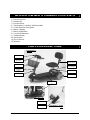
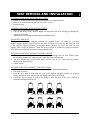
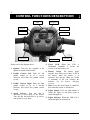
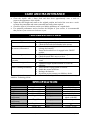
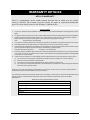
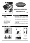
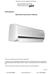
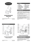
The
OWNER’S MANUAL
Apollo Owner’s Manual
(Part Code: Z40977-00 Rev A)
Page 1 of 11
APOLLO OWNER’S MANUAL CONTENTS
1) Parts Description
2) Introduction
3) Personal Safety
4) Transportation, Assembly and Disassembly
5) Control Functions Description
6) Battery Charging
7) Battery Maintenance
8) Care and Maintenance
9) Troubleshooting
10) Specification
11) Service Record
12) Warranty
PARTS DESCRIPTION
PHOTOGRAPH 1:
SCOOTER
CONTROL POD
HEADLAMP
SEAT (COMPLETE
WITH SEAT STEM)
BASKET
SEAT LOCKING PIN
TILLER
ADJUSTMENT
HANDLE
REAR LAMP
TOWING HANDLE
ANTI-TIP WHEELS
POWER PACK
PHOTOGRAPH 2:
SCOOTER
SHOPPING BASKET
POWER PACK
Apollo Owner’s Manual
(Part Code: Z40977-00 Rev A)
PHOTOGRAPH 3: POWER
PACK
Page 2 of 11
INTRODUCTION
The Wheeltech Apollo has been designed for a single occupant mass of up to 115kg (18
stone).
The Apollo scooter is designed for use indoors and limited outdoor use. The scooter can be
used on pavements and can be used to cross roads. Lights are included on the Apollo for
night time use, however these lights are not suitable for use on roads.
All Medicare Technology medical devices are manufactured to the highest standards in
accordance with EEC/93/42 and are CE marked.
The Apollo scooter is a robust and visually appealing product whilst being a cost-effective
solution to minor mobility problems.
It is essential that you read this user manual fully before operating the product. Please return
your warranty registration form to confirm you have read this manual. If you have any
queries or problems, please contact the distributor from which you purchased the scooter.
Manufacturer: Medicare Technology,
Dale House, Armytage Rd,
Brighouse, West Yorkshire,
Great Britain HD6 1PT.
Tel: +44 1484 727301
Email: [email protected]
Web: www.medicaretechnology.com
PERSONAL SAFETY
The Wheeltech Apollo has been designed for a single occupant mass of up to 115kg (18
stone). The Apollo has been designed for users who experience difficulty or discomfort when
walking for prolonged periods, but have the use of both legs and the physical, visual and
cognitive ability to operate the scooter safely. Failure to comply with these safety guidelines
could result in injury.
GENERAL OPERATING SAFETY PROCEDURES
Make sure that the power is switched off before mounting or dismounting from the scooter.
For your health and comfort, make sure that you adopt a comfortable posture and that you
can operate the controller unit with ease.
EMERGENCY BRAKING
To apply emergency braking whilst using the scooter simply release the wigwag paddle
control and the electromagnetic brake will apply automatically. Alternatively, turn the scooter
off at the key. However, this will cause the scooter to stop abruptly and may cause injury or
damage.
Apollo Owner’s Manual
(Part Code: Z40977-00 Rev A)
Page 3 of 11
PERSONAL SAFETY
FREEWHEEL DEVICE
Before operating the scooter, ensure the freewheel lever is engaged in the ‘DRIVE’ position.
Failure to do could result in injury or damage
TURNING AND USING ON A GRADIENT GUIDELINES
Avoid sharp turns at high speed as this could result in the scooter tipping. This is especially
relevant when turning on a gradient.
The scooter has been designed to climb gradients up to a maximum of 12°. However, other
factors such as the surface of the gradient or the attributes of the user can vary this figure. If
you are in any doubt about travelling up or down a gradient please find an alternative route.
Do not attempt to turn the scooter around whilst on a gradient. Always turn on flat and level
ground.
ELECTROMAGNETIC INTERFERENCE
Powered wheelchairs/scooters may be susceptible to electromagnetic interference (EMI),
which is interfering electromagnetic energy (EM) emitted from sources such as radio stations,
TV stations, amateur radio (HAM) transmitters, two-way radios and cellular phones. The
interference (from radio sources) can cause the powered wheelchair/scooter to release its
brakes, move by itself or move in unintended directions. It can also permanently damage the
main control system. The intensity of the interfering EM energy can be measured in volts per
meter (V/m). Each powered wheelchair/scooter can resist EMI up to a certain intensity. This
is known as the units ‘immunity level’. The higher the immunity level, the greater the
protection. At this current time, current technology is capable of achieving at least a 20 V/m
immunity level, which would provide useful protection from the more common sources of
radiated EMI.
Because EM energy rapidly becomes more intense as one moves closer to the transmitting
antenna (source), the EM fields from hand-held radio sources (transceivers) are of special
concern. It is possible to unintentionally bring high levels of EM energy very close to the
powered wheelchair’s/scooter’s control system whilst using these devices.
The sources of radiated EMI can be broadly classified into three types:
1. Hand-held portable transceivers (transmitters-receivers) with the antenna mounted
directly on the transmitting unit. Examples include citizens band (CB) radios, ‘walkie
talkies’, security, fire, and police transceivers, cellular telephones and other personal
communication devices.
Note : Some cellular telephones and similar devices transmit signals while they are ON, even
when not being used.
2. Medium–range mobile transceivers, such as those used in police cars, fire engines,
ambulances and taxis. These usually have the antenna mounted on the outside of the
vehicle.
3. Long range transmitters and transceivers, such as commercial broadcast transmitter (radio
and TV broadcast antenna towers) and amateur (HAM) radios.
Apollo Owner’s Manual
(Part Code: Z40977-00 Rev A)
Page 4 of 11
PERSONAL SAFETY
Note : Other types of hand-held devices, such as cordless phones, laptop computers, AM/FM
radios, TV sets, CD players, and cassette players, and small appliances, such as electric
shavers and hairdryers, so far as we know, are not likely to cause EMI problems to your
powered wheelchair/scooter.
Following the guidelines set out below should reduce the chances of unintended brake release
or powered wheelchair/scooter movement, which could result in serious harm or injury.
1. Do not operate hand-held transceivers, such as citizens band (CB) radios, or turn ON
personal communication devices, such as cellular phones, while the powered
wheelchair/scooter is turned ON.
2. Be aware of nearby transmitters, such as radio or TV stations, and try to avoid coming
close to them.
3. If unintended movement or brake release occurs, turn the powered wheelchair/scooter
OFF as soon as it is safe to do so.
4. Be aware that adding accessories or components, or modifying the powered
wheelchair/scooter, may make it more susceptible to EMI.
5. Report all incidents of unintended movement or brake release to the powered
wheelchair/scooter manufacturer, and note whether there is a source of EMI nearby.
ASSEMBLING THE APOLLO
1) Ensure the scooter is switched off and the freewheel lever is engaged.
2) Loosen the tiller adjustment handle. Adjust the tiller so that it is in a comfortable
operating position and tighten the tiller adjustment handle to secure. Install shopping
basket if required.
3) Insert the power pack if required. Do this by rolling the wheels of the power pack in to
the back of the cavity in the shroud. Then slowly lower the front end of the power pack in
to the cavity in the shroud. You will hear a click when the power pack is locked in
position. Ensure that you do not get your fingers caught in the handle area whilst
performing this operation (see photograph 2 in Parts Description).
4) Insert the seat. See the next section on “Seat Removal and Installation” for details on how
to do this.
DISASSEMBLING THE APOLLO
1) Ensure the scooter is switched off and the freewheel lever is engaged.
2) Remove the seat as described in the next section “Seat Removal and Installation”
3) Remove the shopping basket. Loosen the tiller adjustment handle and fold down the tiller.
Retighten the tiller adjustment handle.
4) To manually pull the scooter use the carry handle ensuring the scooter runs on the rear
anti-tip wheels.
Apollo Owner’s Manual
(Part Code: Z40977-00 Rev A)
Page 5 of 11
SEAT REMOVAL AND INSTALLATION
TO REMOVE THE SEAT WITH THE SEAT STEM
1. Ensure the seat is in one of the ENGAGED positions (see diagram below)
2. Remove the seat stem locking pin (see Parts Description).
3. Pull the seat up.
TO INSERT THE SEAT WITH THE SEAT STEM
1. Insert the seat stem in to the scooter
2. Line up the holes at the required height and insert the seat stem locking pin through the
scooter and seat stem.
3. Adjust the seat if necessary by following the guidelines below.
TO ROTATE THE SEAT
The seat comes with four engaged positions (see diagram below). To rotate the seat from
another engaged position first lift up the seat lever. Keep the lever held up and rotate the seat
to the required engaged position (see diagram below). Release the lever and twist the seat
slightly until it locks in position. Check the seat is locked in position by trying to twist the
seat. If the seat is locked in position no twisting should occur.
TO REMOVE THE SEAT WITHOUT THE SEAT STEM
1. Lift up the seat lever and turn the seat slightly to disengage the seat lock. Slowly rotate
the seat approximately 45° until you hear a loud click from under the seat.
2. The lever should now be lower than before and the seat in one of the removal positions
shown in the diagram below.
3. Lift the seat up
TO INSERT THE SEAT WITHOUT THE SEAT STEM
1. Insert the seat stem at one of the removal positions shown in the diagram below.
2. Lift up the seat lever.
3. Keep the lever held up and rotate the seat to the required engaged position (see diagram
below). Release the lever and twist the seat slightly until it locks in position.
4. Check the seat is locked in position by trying to twist the seat. If the seat is locked in
position no twisting should occur.
Above: Seat shown in the four possible "ENGAGED" positions
Below: Seat shown in the four possible "REMOVABLE" positionS
Apollo Owner’s Manual
(Part Code: Z40977-00 Rev A)
Page 6 of 11
4.
CONTROL FUNCTIONS DESCRIPTION
6. BATTERY
GAUGE
4. SPEED
SELECTOR DIAL
9. LIGHT
INDICATOR
5. POWER LED
8. LIGHTS
7. HORN
3. CONTROL
PADDLE RIGHT
2. CONTROL
PADDLE LEFT
1. IGNITION
Please refer to the diagram above.
1.
2.
3.
4.
5. Power LED. When this LED is
illuminated constantly it means the
Ignition. Turn the key supplied in the
scooter is on and ready to use.
ignition to switch on the scooter.
6. Battery Gauge. The battery gauge
indicates how much power there is left in
Paddle Control Left. Push the left
the battery when the scooter is in
paddle control to go in a reverse
operation and moving. When the needle
direction, and release the paddle control
is constantly in the red, recharge the
to stop.
batteries (see the battery charging
section)
Paddle Control Right. Push the right
paddle control to go in a forward 7. Horn. Press the horn button to sound the
direction, and release the paddle control
horn when the scooter is switched on.
to stop.
8. Lights button. Press the light button to
switch the lights on and press again to
Speed Selector. Turn this dial to
switch the lights off.
determine to speed range of the scooter.
Turn the dial anti-clockwise to go slower 9. Lights indicator. When this LED is lit is
and clockwise to go faster.
means the lights are switched on.
Apollo Owner’s Manual
(Part Code: Z40977-00 Rev A)
Page 7 of 11
BATTERY CHARGING
The Apollo comes with battery charger and removable power pack (see Parts Description section).
This power pack contains the batteries for recharging. The power pack can be charged either on board
the scooter or when removed. The charger has two LEDs. One will illuminate red when there is power
from the mains to charger. The second LED will illuminate amber whilst charging and then turn green
when charging is almost complete.
To charge the power pack:
1. Switch the scooter off with the ignition key
2. If desired, remove the power pack by squeezing the handle whilst pulling up the handle. When the
pack is removed, pull up the handle to its full extent and drag the power pack on its back wheels
like a suitcase (see photograph 3 in Parts Description).
3. Pull out the rubber protector covering the charge point on the power pack. Insert the charging
socket on the charger supplied.
4. Plug the mains lead into the charger and then in to the power socket and switch on.
5. Leave the batteries to charge for at least 12 hours and the charger’s LED has been green for more
than two hours.
SAFETY PRECAUTIONS
• Do not stand the battery charger on a carpet or other furnishing when in use.
• Always place on a hard surface in a well-ventilated area.
• Do not expose any part of your charger or battery to direct heat (e.g. a naked flame or gas /
electric fire).
• Do not use your battery charger outdoors.
• The charger has integral fan which operates whilst the charger LED is amber. If the LED is lit
amber but the fan is not working, replace the charger. Failure to so could result in damage.
CHANGING THE BATTERIES
• The power pack supplied is a sealed unit. If you need to change the batteries or require an
additional power pack these can be bought from your Medicare Technology dealer.
• Alternatively, Medicare Technology will refurbish your old unit with new batteries. Again, please
enquire with your Medicare Technology dealer.
BATTERY MAINTENANCE
As with most electrically powered mobility products the crux of the performance lies in the treatment
of the batteries. Although sealed batteries are known as zero maintenance that only refers to the acid
level inside the battery. They must still be very well maintained in terms of charging.
Charging Procedure
The rule to follow regarding charging is as follows. Any time that the scooter has been used, even for
ten minutes, it should be put through a charging cycle, not charged for only a couple of hours. This
particular instruction requires following to the letter as partial charging can actually damage the
battery. Also, if either of the batteries was to fail under a year, and no bad cell was evident, they
would not be honoured by the manufacturer’s warranty as there was no defect with the product.
If the vehicle has not been used for a period of 2 weeks or more it is again worth putting it though a
charging cycle just to maintain the optimum performance of those batteries. If the product is not going
to be in use for a period of two weeks or longer, it is advisable to disconnect the batteries so that they
do not run down.
Apollo Owner’s Manual
(Part Code: Z40977-00 Rev A)
Page 8 of 11
CARE AND MAINTENANCE
•
•
•
•
Clean the Apollo with a damp cloth and dust down approximately once a week to
preserve the appearance of the Apollo.
Adjust the tiller height and return to the original position and swivel the seat once a week
to ensure the parts adjust and remove smoothly and easily when required.
Check for signs of wear and tear on the tyres and the upholstery on a regular basis.
For optimum performance and to increase the lifespan of your scooter, it is recommended
that you have your scooter serviced once a year.
TROUBLESHOOTING
Symptom
The scooter will not switch on
Remedy
Try recharging the battery
Check the fuse and circuit breaker in the scooter
The scooter switches on, but
Ensure there is enough power in the batteries. If not,
the scooter will not move.
recharge the batteries.
• Ensure the freewheel lever is engaged in the ‘DRIVE’
position.
The scooter appears slow
• Check the battery power level and recharge
• Check the speed dial is not set to slow.
The seat turns when in
• Slowly rotate the seat until it drops in to place and is
operation
secure
The handlebar appears loose
• Tighten the height adjustment handle to secure the
handlebar
Horn is sounding involuntarily
• Ensure that the wigwag paddle is released.
• Switch the scooter off and on.
• Recharge the batteries.
• If problem persists contact your Medicare dealer.
If any of the above problems persist or an unlisted problem occurs, then contact your
Medicare Technology dealer.
•
•
•
SPECIFICATION
Code
Description
Length
Height
Width
Weight
(with
components)
Weight
(without
components)
Maximum User Mass
Colour
Apollo Owner’s Manual
AP001
Apollo scooter
1170mm (46”)
870mm (34”)
560mm (22”)
52kg (114lb)
Battery
Charger
Front wheel
Rear tyre
Top speed
Driving system
27kg (59lb)
Braking system
115kg (18 stone)
Metallic Red
Climb angle
Range
(Part Code: Z40977-00 Rev A)
17ah power pack
24V 3A
200 x 50 SOLID
2x 3.00-4
4mph (6kph)
Direct drive to rear
wheels (with diff.)
Electromagnetic
12°
15 mile ( 25 km)
Page 9 of 11
SERVICE RECORD
YEAR
Section 1: Controls
On/Off Switch
Wigwag Paddle
Output plug
Operation
Dynamic Braking
Static Braking
Section 2: Batteries
Type (SLA/AGM/Gl)
Compartment
Connections
Wiring
Battery test
Section 3: Wheels
Type Pressure
Tyre Wear
Wheel Bearings
Wheel Nuts Tight
Tab Washers
Lubricated / Greased
Section 4: Chassis
General Condition
Swivel Bearings
Tiller Pivot
List Items Repaired
Service
Dealer
Name
1
Year 1
2
3
4
Year 2
5
YEAR
Section 5: Motor
Wiring
Mounting
Function
Noise Level
Commutator Cleaned
Brushes
Section 6: Upholstery
Seat
Back
Armpads
Section 7: Body
Mounting
Condition
Seat Mechanism
Seat Adjustment
Section 8: Electrics
Condition of Loom
Audible Warnings
Charger
Charger Connection
Sect 9: Drive Train
Transaxle Seals
Transaxle Noise Level
Transaxle Mount Bkts
Section 10: Test Run
Test Run
Year 3
Year 4
1
2
3
4
5
Year 5
Sign / Date
Customer Name
Date of Purchase
Address
Colour
Serial No.
Options Included
Postcode
Apollo Owner’s Manual
(Part Code: Z40977-00 Rev A)
Page 10 of 11
WARRANTY DETAILS
APOLLO WARRANTY
There is a comprehensive twelve month warranty from the date on which your new Apollo
scooter is delivered. The warranty covers the scooter for repairs or replacement during this
period. For more detail, please see the Warranty Conditions below.
Warranty Conditions:
1.
Any work or replacement part installation must be carried out by an authorised Medicare Technology dealer / service
agent.
2.
To apply the warranty should your scooter require attention please contact the designated service agent listed below.
3.
Should any part of the scooter require repair or full or part replacement, as a result of a manufacturing or material
defect within twelve months of receiving the scooter, parts will be supplied free of charge.
Note:
The guarantee is not transferable
4.
Any repaired or replaced parts will be covered by this warranty for the balance of the warranty period on the scooter.
5.
Parts replaced after the original warranty has expired will by covered by a three months warranty.
6.
Consumable items supplied will not generally be covered during the normal warranty period unless such items require
repair or replacement clearly as a direct result of a manufacturing or material defect.
Such items include (among others):
upholstery, tyres and batteries.
7.
The above warranty conditions apply to brand new scooters purchased at the full retail price. If you are unsure whether
your scooter is covered, check with the service agent. Secondhand scooters supplied by Medicare Technology usually
come with a six-month warranty.
8.
Under normal circumstances, no responsibility will be accepted where the scooter has failed as a direct result of:
a)
The scooter part not having been maintained in accordance with the manufacturer’s recommendations.
b)
Failure to use the manufacturer’s specified parts
c)
The scooter or part having been damaged due to neglect, accident or improper use
d)
The scooter or part having been altered from the manufacturer’s specifications or repairs having been attempted
before the service agent is notified
Please note your local service agent’s contact details in the box below. In the event of your scooter requiring attention,
contact them and give all relevant details so they can act quickly.
The manufacturer reserves the right to alter without notice any weights, measurements or other technical data shown in this
manual. All figures, measurements and capacities shown in this manual are approximate and do not constitute
specifications.
Medicare Technology authorised Service Agent
Name
Address
Tel
Postcode
Apollo Owner’s Manual
(Part Code: Z40977-00 Rev A)
Page 11 of 11