1
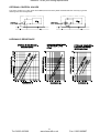
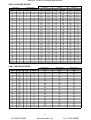
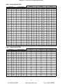
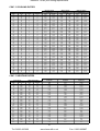
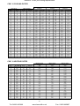
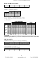
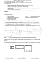
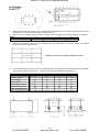
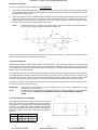
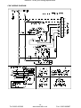
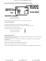
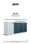
Heronhill - for all your Airking requirements
TECHNICAL MANUAL
for CWC CHILLED WATER CASSETTE.
This manual provides technical and installation information for CASSETTE 962 series fan coils.
INDEX
PAGE
GENERAL
Part Numbers, Dimensions and Weights
Unit Features/Accessories
Optional Control Valves
SELECTION
Hydraulic Resistance
Performance Data, Airflows
Coil Water Volumes, Optional Electric Heating
Sound Power and Sound Pressure Levels
ELECTRICAL
Electrical Data, Recommended Fuse Sizes
UNIT
INSTALLATION
CWC
Pipework
Electrical Connections
IMI Remote Controller
Fascia Mounting
Condensate Pump/Overflow Protection
Fresh Air/Adjacent Room Supply
WIRING
DIAGRAM
CWC Units
14
OPERATION
CWC
User Maintenance
15
16
IMI Air Conditioning Ltd.
Armytage Road, Brighouse,
West Yorkshire. HD6 1QF
Tel: (01484) 405600
Fax: (01484) 721949
2
2
3
3
4-7
8
8
8
9 - 11
11
11
12
12 - 13
13
13
A subsidiary company of IMI plc
96208019-02
Tel: 01823 665660
-1-
www.heronhill.co.uk
Fax: 01823 665807
Heronhill - for all your Airking requirements
IMI AIR CONDITIONING LIMITED-CASSETTE CEILING MOUNTED CHILLED
WATER UNITS
PART NUMBERS
CASSETTE CWC UNITS
Models
8
9
13
19
Part Number (without condensate pump)
96200001
96200002
96200004
96200005
Part Number (with condensate pump)
96200051
96200052
96200054
96200055
UNPACKED DIMENSIONS AND WEIGHTS
CWC UNITS
Model
CWC
8
9
13
19
HEIGHT mm
338
338
338
338
WIDTH mm
647
747
947
1247
DEPTH mm
647
647
647
647
WEIGHT kg
24
31
39
48
PACKED DIMENSIONS AND WEIGHTS
CWC UNITS
Model
CWC
8
9
13
19
HEIGHT mm
510
510
510
510
WIDTH mm
680
780
980
1280
DEPTH mm
710
710
710
710
WEIGHT kg
34
43
52
63
FEATURES/ACCESSORIES
CWC UNITS
CWC
Manually adjustable air deflectors
STD
Automatically adjusted air deflectors
*
Electric/LPHW heating
*
Electromechanical remote thermostat
*
STD
3 fan speeds
Branch duct and fresh air inlet
*
Programmable timer
*
Condensate pump
*
STD
Long life washable filter
*
2 or 3 way valve arrangements
3 way discharge
Key: * = factory/site option.
Tel: 01823 665660
STD
STD = standard.
-2-
www.heronhill.co.uk
Fax: 01823 665807
Heronhill - for all your Airking requirements
OPTIONAL CONTROL VALVES
The choice of either 2 or 3 way valves are available, these are factory fitted and sited within the valve tray to give the
following water flow arrangements.
HYDRAULIC RESISTANCE
Tel: 01823 665660
-3-
www.heronhill.co.uk
Fax: 01823 665807
Heronhill - for all your Airking requirements
CWC 8 COOLING DUTIES
Room Air On
db /C
wb /C
27
19
21
15
21
15
21
15
21
15
21
15
21
15
21
15
21
15
21
15
24
17
24
17
24
17
24
17
24
17
24
17
24
17
24
17
24
17
27
19
27
19
27
19
27
19
27
19
27
19
27
19
27
19
27
19
29
19
29
19
29
19
29
19
29
19
29
19
29
19
29
19
29
19
CW Temperature
IN /C
OUT /C
6
11
5
9
5
11
5
13
7
11
7
13
7
15
9
13
9
15
9
17
5
9
5
11
5
13
7
11
7
13
7
15
9
13
9
15
9
17
5
9
5
11
5
13
7
11
7
13
7
15
9
13
9
15
9
17
5
9
5
11
5
13
7
11
7
13
7
15
9
13
9
15
9
17
Minimum Speed
0.077 m3/s
Total
Sensible
1.79
1.26
1.20
0.95
0.84
0.79
0.71
0.71
0.85
0.79
0.67
0.67
0.58
0.58
0.62
0.62
0.53
0.53
0.45
0.45
1.65
1.18
1.25
1.01
0.97
0.89
1.32
1.03
0.89
0.86
0.78
0.78
0.96
0.88
0.73
0.73
0.65
0.65
2.12
1.41
1.77
1.26
1.29
1.05
1.79
1.26
1.42
1.11
1.03
0.95
1.44
1.11
0.99
0.94
0.84
0.84
2.14
1.57
1.81
1.42
1.31
1.22
1.82
1.43
1.46
1.27
1.10
1.10
1.47
1.28
1.12
1.12
0.97
0.97
Medium Speed
0.104 m3/s
Total
Sensible
2.20
1.59
1.48
1.20
0.96
0.96
0.85
0.85
1.05
1.01
0.80
0.80
0.69
0.69
0.81
0.81
0.64
0.64
0.53
0.53
2.03
1.49
1.57
1.29
1.09
1.09
1.61
1.31
1.08
1.08
0.93
0.93
1.17
1.12
0.88
0.88
0.77
0.77
2.60
1.77
2.18
1.58
1.63
1.36
2.19
1.59
1.75
1.40
1.16
1.16
1.76
1.41
1.26
1.21
1.01
1.01
2.63
1.98
2.22
1.80
1.69
1.58
2.22
1.80
1.78
1.62
1.36
1.36
1.79
1.62
1.43
1.43
1.16
1.16
Maximum Speed
0.134 m3/s
Total
Sensible
2.57
1.91
1.73
1.45
1.16
1.16
0.97
0.97
1.23
1.23
0.92
0.92
0.79
0.79
0.99
0.99
0.73
0.73
0.61
0.61
2.38
1.79
1.84
1.56
1.25
1.25
1.89
1.58
1.33
1.33
1.06
1.06
1.36
1.36
1.08
1.08
0.88
0.88
3.05
2.12
2.56
1.91
1.95
1.66
2.56
1.91
2.04
1.70
1.40
1.40
2.05
1.70
1.48
1.48
1.16
1.16
3.08
2.36
2.59
2.17
2.00
1.93
2.59
2.17
2.08
1.96
1.69
1.69
2.08
1.96
1.73
1.73
1.45
1.45
CWC 8 HEATING DUTIES
Room Air On
db /C
wb /C/%RH
20
12
10
50%
10
50%
10
50%
10
50%
10
50%
10
50%
15
50%
15
50%
15
50%
15
50%
15
50%
15
50%
20
50%
20
50%
20
50%
20
50%
20
50%
20
50%
25
50%
25
50%
25
50%
25
50%
25
50%
25
50%
LPHW Temperature
IN /C
OUT /C
80
70
90
80
90
75
80
70
80
65
65
55
65
50
90
80
90
75
80
70
80
65
65
55
65
50
90
80
90
75
80
70
80
65
65
55
65
50
90
80
90
75
80
70
80
65
65
55
65
50
Minimum Speed
0.077 m3/s
Total
4.15
5.83
5.59
5.03
4.79
3.84
3.58
5.37
5.14
4.58
4.34
3.40
3.15
4.92
4.69
4.14
3.91
2.98
2.72
4.48
4.25
3.71
3.48
2.56
2.30
Medium Speed
0.104 m3/s
Total
5.26
7.39
7.07
6.37
6.05
4.85
4.51
6.81
6.50
5.81
5.49
4.30
3.97
6.24
5.94
5.25
4.94
3.76
3.44
5.69
5.38
4.71
4.40
3.24
2.91
Maximum Speed
0.134 m3/s
Total
6.37
8.94
8.54
7.71
7.30
5.85
5.44
8.25
7.86
7.03
6.63
5.20
4.79
7.57
7.18
6.36
5.97
4.55
4.15
6.90
6.52
5.71
5.32
3.92
3.52
-4-
Tel: 01823 665660
www.heronhill.co.uk
Fax: 01823 665807
Heronhill - for all your Airking requirements
CWC 9 COOLING DUTIES
Room Air On
db /C
wb /C
27
19
21
15
21
15
21
15
21
15
21
15
21
15
21
15
21
15
21
15
24
17
24
17
24
17
24
17
24
17
24
17
24
17
24
17
24
17
27
19
27
19
27
19
27
19
27
19
27
19
27
19
27
19
27
19
29
19
29
19
29
19
29
19
29
19
29
19
29
19
29
19
29
19
CW Temperature
IN /C
OUT /C
6
11
5
9
5
11
5
13
7
11
7
13
7
15
9
13
9
15
9
17
5
9
5
11
5
13
7
11
7
13
7
15
9
13
9
15
9
17
5
9
5
11
5
13
7
11
7
13
7
15
9
13
9
15
9
17
5
9
5
11
5
13
7
11
7
13
7
15
9
13
9
15
9
17
Minimum Speed
0.098 m3/s
Total
Sensible
2.39
1.65
1.62
1.25
1.10
1.02
0.90
0.90
1.19
1.06
0.85
0.85
0.74
0.74
0.85
0.85
0.68
0.68
0.57
0.57
2.18
1.54
1.79
1.36
1.23
1.13
1.76
1.35
1.32
1.16
0.99
0.99
1.32
1.16
0.93
0.93
0.82
0.82
2.77
1.83
2.40
1.66
1.95
1.47
2.35
1.64
1.97
1.47
1.40
1.25
1.92
1.45
1.49
1.28
1.07
1.07
2.80
2.04
2.44
1.87
2.00
1.68
2.39
1.85
2.01
1.68
1.49
1.47
1.95
1.66
1.54
1.49
1.25
1.25
Medium Speed
0.122 m3/s
Total
Sensible
2.77
1.95
1.89
1.48
1.35
1.24
1.03
1.03
1.39
1.26
0.96
0.96
0.84
0.84
1.02
1.02
0.77
0.77
0.65
0.65
2.54
1.83
2.08
1.62
1.34
1.31
2.05
1.60
1.54
1.39
1.12
1.12
1.53
1.38
1.14
1.14
0.93
0.93
3.22
2.16
2.80
1.97
2.29
1.75
2.74
1.94
2.28
1.75
1.70
1.51
2.22
1.72
1.73
1.53
1.22
1.22
3.25
2.41
2.84
2.22
2.34
2.01
2.77
2.19
2.33
2.00
1.77
1.77
2.26
1.97
1.78
1.78
1.53
1.53
Maximum Speed
0.165 m3/s
Total
Sensible
3.36
2.44
2.29
1.86
1.67
1.58
1.21
1.21
1.68
1.59
1.27
1.27
0.98
0.98
1.29
1.29
0.91
0.91
0.76
0.76
3.08
2.28
2.53
2.03
1.80
1.73
2.48
2.01
1.87
1.76
1.39
1.39
1.83
1.74
1.46
1.46
1.10
1.10
3.91
2.68
3.39
2.45
2.78
2.20
3.30
2.41
2.76
2.19
2.08
1.93
2.67
2.15
2.08
1.92
1.62
1.62
3.94
3.00
3.43
2.78
2.83
2.53
3.33
2.74
2.80
2.51
2.25
2.25
2.71
2.48
2.24
2.24
1.95
1.95
CWC 9 HEATING DUTIES
Room Air On
db /C
wb /C/%RH
20
12
10
50%
10
50%
10
50%
10
50%
10
50%
10
50%
15
50%
15
50%
15
50%
15
50%
15
50%
15
50%
20
50%
20
50%
20
50%
20
50%
20
50%
20
50%
25
50%
25
50%
25
50%
25
50%
25
50%
25
50%
LPHW Temperature
IN /C
OUT /C
80
70
90
80
90
75
80
70
80
65
65
55
65
50
90
80
90
75
80
70
80
65
65
55
65
50
90
80
90
75
80
70
80
65
65
55
65
50
90
80
90
75
80
70
80
65
65
55
65
50
Minimum Speed
0.098 m3/s
Total
5.31
7.45
7.16
6.43
6.14
4.91
4.61
6.86
6.58
5.86
5.57
4.36
4.06
6.29
6.01
5.30
5.01
3.82
3.52
5.72
5.45
4.75
4.47
3.29
2.98
Medium Speed
0.122 m3/s
Total
6.32
8.86
8.50
7.65
7.29
5.83
5.46
8.17
7.82
6.97
6.62
5.18
4.81
7.49
7.14
6.31
5.96
4.54
4.18
6.82
6.48
5.66
5.31
3.91
3.55
Maximum Speed
0.165 m3/s
Total
7.96
11.14
10.68
9.62
9.15
7.33
6.84
10.28
9.83
8.78
8.31
6.51
6.03
9.44
8.99
7.95
7.49
5.70
5.23
8.61
8.16
7.13
6.68
4.92
4.45
-5-
Tel: 01823 665660
www.heronhill.co.uk
Fax: 01823 665807
Heronhill - for all your Airking requirements
CWC 13 COOLING DUTIES
Room Air On
db /C
wb /C
27
19
21
15
21
15
21
15
21
15
21
15
21
15
21
15
21
15
21
15
24
17
24
17
24
17
24
17
24
17
24
17
24
17
24
17
24
17
27
19
27
19
27
19
27
19
27
19
27
19
27
19
27
19
27
19
29
19
29
19
29
19
29
19
29
19
29
19
29
19
29
19
29
19
CW Temperature
IN /C
OUT /C
6
11
5
9
5
11
5
13
7
11
7
13
7
15
9
13
9
15
9
17
5
9
5
11
5
13
7
11
7
13
7
15
9
13
9
15
9
17
5
9
5
11
5
13
7
11
7
13
7
15
9
13
9
15
9
17
5
9
5
11
5
13
7
11
7
13
7
15
9
13
9
15
9
17
Minimum Speed
0.120 m3/s
Total
Sensible
2.99
2.06
2.01
1.55
1.32
1.24
1.12
1.12
1.44
1.30
1.05
1.05
0.92
0.92
1.00
1.00
0.84
0.84
0.71
0.71
2.74
1.93
2.14
1.66
1.53
1.40
2.20
1.69
1.40
1.35
1.22
1.22
1.62
1.44
1.15
1.15
1.02
1.02
3.50
2.30
2.98
2.06
2.03
1.66
2.97
2.06
2.41
1.82
1.63
1.50
2.41
1.82
1.74
1.55
1.32
1.32
3.53
2.56
3.03
2.33
2.26
1.99
3.01
2.32
2.47
2.08
1.74
1.74
2.46
2.08
1.83
1.82
1.53
1.53
Medium Speed
0.179 m3/s
Total
Sensible
3.96
2.82
2.68
2.13
1.66
1.66
1.41
1.41
1.94
1.80
1.33
1.33
1.15
1.15
1.45
1.45
1.06
1.06
0.88
0.88
3.64
2.63
2.90
2.30
1.81
1.81
2.92
2.31
2.06
1.95
1.54
1.54
2.15
1.99
1.55
1.55
1.28
1.28
4.64
3.12
3.97
2.82
3.11
2.46
3.93
2.80
3.21
2.50
2.00
2.00
3.18
2.49
2.37
2.17
1.68
1.68
4.68
3.49
4.03
3.19
3.19
2.84
3.98
3.17
3.28
2.87
2.48
2.48
3.23
2.85
2.54
2.54
2.10
2.10
Maximum Speed
0.243 m3/s
Total
Sensible
4.81
3.53
3.27
2.68
2.21
2.21
1.65
1.65
2.35
2.28
1.71
1.71
1.34
1.34
1.84
1.84
1.24
1.24
1.02
1.02
4.42
3.30
3.54
2.91
2.32
2.32
3.54
2.91
2.54
2.50
1.81
1.81
2.59
2.52
2.05
2.05
1.49
1.49
5.63
3.00
4.83
3.54
3.82
3.12
4.75
3.50
3.89
3.15
2.69
2.69
3.82
3.12
2.87
2.75
2.21
2.21
5.67
4.35
4.89
4.01
3.91
3.60
4.79
3.97
3.96
3.62
3.18
3.18
3.88
3.59
3.22
3.22
2.74
2.74
CWC 13 HEATING DUTIES
Room Air On
db /C
wb /C/%RH
20
12
10
50%
10
50%
10
50%
10
50%
10
50%
10
50%
15
50%
15
50%
15
50%
15
50%
15
50%
15
50%
20
50%
20
50%
20
50%
20
50%
20
50%
20
50%
25
50%
25
50%
25
50%
25
50%
25
50%
25
50%
LPHW Temperature
IN /C
OUT /C
80
70
90
80
90
75
80
70
80
65
65
55
65
50
90
80
90
75
80
70
80
65
65
55
65
50
90
80
90
75
80
70
80
65
65
55
65
50
90
80
90
75
80
70
80
65
65
55
65
50
Minimum Speed
0.120 m3/s
Total
6.67
9.36
9.00
8.09
7.72
6.18
5.79
8.62
8.26
7.37
7.00
5.48
5.09
7.09
7.54
6.66
6.30
4.80
4.41
7.18
6.84
5.96
5.61
4.13
3.73
Medium Speed
0.179 m3/s
Total
9.18
12.88
12.35
11.12
10.58
8.47
7.92
11.87
11.35
10.13
9.61
7.52
6.98
10.89
10.38
9.17
8.65
6.59
6.05
9.92
9.42
8.22
7.71
5.67
5.13
Maximum Speed
0.243 m3/s
Total
11.58
16.22
15.54
14.00
13.30
10.65
9.94
14.97
14.30
12.77
12.08
9.46
8.76
13.74
13.08
11.57
10.89
8.29
7.60
12.53
11.87
10.38
9.71
7.15
6.4
-6-
Tel: 01823 665660
www.heronhill.co.uk
Fax: 01823 665807
Heronhill - for all your Airking requirements
CWC 19 COOLING DUTIES
Room Air On
db /C
wb /C
27
19
21
15
21
15
21
15
21
15
21
15
21
15
21
15
21
15
21
15
24
17
24
17
24
17
24
17
24
17
24
17
24
17
24
17
24
17
27
19
27
19
27
19
27
19
27
19
27
19
27
19
27
19
27
19
29
19
29
19
29
19
29
19
29
19
29
19
29
19
29
19
29
19
CW Temperature
IN /C
OUT /C
6
11
5
9
5
11
5
13
7
11
7
13
7
15
9
13
9
15
9
17
5
9
5
11
5
13
7
11
7
13
7
15
9
13
9
15
9
17
5
9
5
11
5
13
7
11
7
13
7
15
9
13
9
15
9
17
5
9
5
11
5
13
7
11
7
13
7
15
9
13
9
15
9
17
Minimum Speed
0.129 m3/s
Total
Sensible
3.46
2.36
2.32
1.77
1.59
1.43
1.31
1.31
1.64
1.45
1.22
1.22
1.07
1.07
1.14
1.14
0.98
0.98
0.83
0.83
3.17
2.21
2.37
1.84
1.85
1.61
2.56
1.92
1.69
1.55
1.42
1.42
1.88
1.63
1.34
1.34
1.18
1.18
4.05
2.63
3.45
2.35
2.44
1.92
3.45
2.35
2.77
2.05
1.97
1.73
2.81
2.07
1.81
1.67
1.54
1.54
4.09
2.92
3.51
2.65
2.50
2.21
3.50
2.64
2.85
2.36
2.03
202
2.86
2.36
2.00
2.00
1.78
1.78
Medium Speed
0.179 m3/s
Total
Sensible
4.47
3.08
3.02
2.32
1.83
1.79
1.60
1.60
2.19
1.95
1.50
1.50
1.30
1.30
1.53
1.53
1.20
1.20
1.00
1.00
4.09
2.88
3.24
2.50
2.11
2.02
3.30
2.52
1.95
1.95
1.74
1.74
2.45
2.16
1.65
1.65
1.45
1.45
5.21
3.42
4.48
3.09
3.38
2.61
4.43
3.07
3.63
2.72
2.24
2.17
3.61
2.71
2.67
2.33
1.89
1.89
5.27
3.81
4.55
3.48
3.52
3.03
4.49
3.45
3.72
3.11
2.49
2.49
3.68
3.10
2.78
2.73
2.19
2.19
Maximum Speed
0.243 m3/s
Total
Sensible
5.56
3.91
3.77
2.96
2.30
2.30
1.89
1.89
2.74
2.50
1.79
1.79
1.54
1.54
2.01
2.01
1.42
1.42
1.18
1.18
5.10
3.66
4.10
3.21
2.44
2.44
4.11
3.21
2.94
2.72
2.07
2.07
3.04
2.76
2.15
2.15
1.71
1.71
6.48
4.32
5.59
3.92
4.41
3.43
5.50
3.88
4.54
.348
2.77
2.77
4.46
3.45
3.38
3.02
2.25
2.25
6.54
4.83
5.67
4.43
4.54
3.95
5.57
4.39
4.63
3.98
3.44
3.44
4.54
3.95
3.53
3.53
2.91
2.91
CWC 19 HEATING DUTIES
Room Air On
db /C
wb /C/%RH
20
12
10
50%
10
50%
10
50%
10
50%
10
50%
10
50%
15
50%
15
50%
15
50%
15
50%
15
50%
15
50%
20
50%
20
50%
20
50%
20
50%
20
50%
20
50%
25
50%
25
50%
25
50%
25
50%
25
50%
25
50%
LPHW Temperature
IN /C
OUT /C
80
70
90
80
90
75
80
70
80
65
65
55
65
50
90
80
90
75
80
70
80
65
65
55
65
50
90
80
90
75
80
70
80
65
65
55
65
50
90
80
90
75
80
70
80
65
65
55
65
50
Minimum Speed
0.129 m3/s
Total
7.53
10.57
10.19
9.15
8.75
7.00
6.58
9.73
9.35
8.32
7.93
6.20
5.78
8.90
8.53
7.51
7.13
5.43
4.99
8.09
7.72
6.73
6.35
4.67
4.22
Medium Speed
0.179 m3/s
Total
9.91
13.90
13.36
12.01
11.47
9.18
8.62
12.80
12.28
10.94
10.41
8.14
7.58
11.72
11.21
9.89
9.36
7.13
6.56
10.67
10.16
8.86
8.34
6.14
5.56
Maximum Speed
0.243 m3/s
Total
12.66
17.74
17.03
15.32
14.60
11.69
10.95
16.36
15.66
13.97
13.26
10.38
9.65
15.00
14.31
12.64
11.94
9.09
8.37
13.66
12.99
11.33
10.64
7.83
7.10
-7-
Tel: 01823 665660
www.heronhill.co.uk
Fax: 01823 665807
Heronhill - for all your Airking requirements
WATER VOLUME IN COILS (litres)
8
9
13
19
COOLING
COIL
1.0
1.2
1.6
2.1
HEATING
0.4
0.5
0.6
0.8
OPTIONAL ELECTRIC HEATING
at 230V 50Hz
at 240V 50Hz
CWC
(kW)
(kW)
8
1.4
1.5
9
1.8
2.0
13
2.3
2.5
19
3.4
3.75
SOUND POWER and SOUND PRESSURE LEVELS
962 SERIES CWC
SOUND POWER LEVELS
SOUND PRESSURE
LEVELS
Frequency Hz
MODEL
SPEED
Min
49.1
51.4
8
Med
50.6
52.7
Max
54.3
57.2
Min
50.2
52.0
Med
52.6
Max
56.2
Min
Med
9
13
19
125
250
500
1K
2K
4K
dBA
dBA
NC
51.2
47.1
41.0
40.7
52.7
31.7
24
52.7
48.8
41.6
37.8
53.6
32.6
26
54.3
50.9
43.9
40.8
55.8
34.8
28
50.9
47.5
41.0
39.5
52.7
31.7
25
54.1
53.6
50.6
43.1
39.6
55.1
34.1
28
56.3
55.2
53.1
45.3
40.6
57.0
36.0
30
50.3
51.7
50.4
46.8
43.1
44.4
53.5
32.5
26
54.8
54.8
53.9
50.4
44.6
44.3
55.8
34.8
28
30
Max
58.5
57.4
55.0
52.4
46.0
44.8
57.2
36.2
Min
50.7
52.3
49.7
44.8
35.7
30.8
50.2
29.2
22
Med
55.3
55.6
53.7
49.6
41.2
34.6
54.6
33.6
27
58.3
58.2
55.3
52.3
43.9
38.0
56.8
35.8
30
Max
Sound Power Levels were obtained in full conformity with BS 4196: Part 5: 1981. Quantities are shown in dB with a standard
reference of 1 pW.
Sound Pressure Levels are dB relative to 2 x 10⁻⁵N/m2 and are calculated from the results under anechoic conditions and are
quoted as an average of all points on a hemisphere of a radius of 3m away, 1m down from the centre of the unit.
ELECTRICAL DATA
CWC Maximum Running Current in Amps (At 230 V, 50 Hz).
Model
8
9
13
19
Standard
0.3
0.3
0.3
0.4
With Electric Htg
6.3
8.3
10.4
15.6
19
RECOMMENDED FUSE SIZES (Amps)
Model
8
9
13
Standard
3
3
3
3
With Electric Htg
10
13
13
20
-8-
Tel: 01823 665660
www.heronhill.co.uk
Fax: 01823 665807
Heronhill - for all your Airking requirements
962 SERIES CWC CASSETTE INSTALLATION
The 962 SERIES CWC CASSETTE is designed to operate within a suspended false ceiling.
The installer supplies:
Remote thermostat (available separately, part number 96000320)
4 lengths of screwed rod (M8, M10 or 3/8" OD) with 12 nuts, to suspend the chassis.
Method of securing screwed rod to solid ceiling e.g. Rawl bolt shields.
All mains wiring, with suitable isolation.
Interconnecting wires for remote thermostat, (available from IMI in 100m drums; part number 00526116S).
Insulated pipework.
2 screws to secure the remote thermostat.
Condensate drain (21.5mm OD for gravity drain or 8mm ID if a condensate pump is fitted).
Unpacking
Carefully unfasten the box and lift off the cardboard sleeve to gain access to the unit.
The following are supplied:
*
*
*
*
Cassette unit complete with fascia
2 Suspension brackets
Cardboard template for marking out rod
mounting centres
Envelope containing operating
instructions for the end user
*
*
*
*
8 washers 4 screws 4 pointed screws 2 cable clamps -
Use on suspension brackets
Chassis to suspension brackets
Fascia frame to chassis
External cable entries
The fascia must be removed, (as shown below), and carefully set aside prior to mounting the chassis.
1
2
3
Remove the smaller rear panel and filter by depressing the panel above each rear corner to release the latches.
Hinge the panel upwards and disengage the panel hooks.
Remove the fascia panel by undoing the 2 captive screws above the fan deck. Raise the angled edge of the
panel whilst sliding it forwards to disengage the locating hooks on the front corners.
Remove the fascia frame by depressing the spring latches on the inside of the chassis on opposite corners
to disengage the tabs on the frame. The frame may now be carefully lifted away from the chassis.
Chassis Mounting
NOTE:
It is generally easier to fit kits prior to mounting the unit and connecting the pipework.
Units are sized to allow each chassis to fit conveniently in a standard tiled ceiling although it is recommended that the ceiling
is built with the unit in position; the CWC 8 in a 600mm x 600mm tile space and the CWC 9 to 13 in a 1200mm x 600mm
tile space.
Units may be fitted into plasterboard ceilings but access traps for the condensate pump and pipework must be provided.
Location of the unit will depend on the room shape, load and number of units installed. Typical options are:
Tel: 01823 665660
-9-
www.heronhill.co.uk
Fax: 01823 665807
Heronhill - for all your Airking requirements
1
2
Determine the position for the unit; the air inlet must be at least 400mm from the nearest wall. Also ensure that the
position does not interfere with light fittings, sprinkler heads, etc..
Identify the type of ceiling and ensure that the mounting surface will support the operating weight of the cassette:
MODEL
OPERATING WEIGHT (kg)
3
8
9
13
19
25.5
32.5
41.0
51.0
If fitting the unit after the ceiling has been installed, remove the ceiling tile(s) to accept the chassis, plus adjacent
tiles on each side for general access.
* Remove these tiles for complete installation access.
4
The chassis should be supported by four screwed rods and 12 nuts (M8, M10 or 3/8"OD) supplied by the installer.
Rod mounting centres are shown at + - + below; use the template provided to mark these out.
Model
8
9
13
19
A (Chassis depth)
568
568
568
568
B (Chassis width)
565
665
865
1165
C (Fascia depth)
647
647
647
647
D (Fascia width)
647
747
947
1247
E (Height above ceiling)
293
293
293
293
F (Rod mounting centres)
494
494
794
794
G (Rod mounting centres)
604
604
604
604
H (Base to suspension hook)
92
92
92
92
Tel: 01823 665660
-10-
www.heronhill.co.uk
Fax: 01823 665807
Heronhill - for all your Airking requirements
On plasterboard suspended ceilings, remove sufficient of the ceiling to
give clearance for the unit to be fitted, and for access to pipework and
electrics at the right hand side (motor end); a trap door should be left for
service access to electrics and pipework.
On reinforced concrete ceilings use Rawl bolt shields or equivalent.
On wooden ceilings use battens for a mounting frame.
5
6
7
8
9
10
If a heater kit or LPHW coil is to be used, fit prior to mounting the
unit.
Hang the four mounting rods; using twelve nuts and eight washers
support the suspension brackets so that the hooks are
approximately 120 - 130mm above the lower surface of the
suspended ceiling
Remove the right hand blanking plate (7 screws) from the chassis
to expose the open ends of the coil inlet and outlet pipes; the outlet
pipe is identifiable by the bleed valve.
Remove and retain the finger guard (1 screw)
Carefully lift the chassis up to the suspension brackets and locate
the hooks on the suspension brackets into the chassis. Use the
nuts to jack the chassis up until the flange is flush with the
suspended ceiling. Ensure that the chassis is level in two
directions, even if the ceiling is not; failure to do so may result
in incorrect condensate drainage or noisy fan operation. Lock
the nuts securely.
Secure the chassis to the suspension brackets using the four
screws provided, (2 each side).
PIPEWORK
IMPORTANT:
Do NOT use solenoid valves with this unit as they will render the overflow protection switch useless.
If no alternative is available, replace the switch with a length of 1.5 square millimetres diameter wire.
Pipework is terminated at the right hand end of the unit and is 15mm waterpipe.
Pipe runs can be brazed or compression fittings may be used.
When brazing, mask the chassis to prevent burning of the insulation.
It is preferable to fit valves once the unit has been mounted in the ceiling. These are available factory
fitted, with compression fittings, or as a 'field-fit' kit.
ELECTRICAL CONNECTIONS
Refer to page 8 for all electrical data.
All mains and control cables must be supplied and fitted by the installer.
The installer wiring must be carried out in accordance with IEE regulations and local codes.
All cables must be size compatible with the recommended fuse for a given system.
An isolator switch should be positioned within easy reach of the unit.
The equipment MUST be earthed.
Cable glands suitable for stranded cables are supplied and should be used to secure all cables. Installers must supply a
method of securing any solid sheathed cable.
FIRE LINK
In order to automatically switch off the fan in the event of a fire, it is necessary to fit an external switch (240V, 3A, closed
to run, volt free contact) between terminal block terminal 2 and the IMI remote control thermostat (if fitted) terminal 2. This
switch should be operated by the building's fire alarm or BMS system.
Tel: 01823 665660
-11-
www.heronhill.co.uk
Fax: 01823 665807
Heronhill - for all your Airking requirements
INSTALLATION of the IMI REMOTE CONTROLLER, (if used).
The thermostat should be wired with 7 cores of double insulated 230V cable, 0.5 square millimetres minimum, (available
from IMI in 100m drums; part number 00526116S), preferably in plastic conduit for good appearance.
Select a position to mount the thermostat taking into account the following comments:
a
b
c
d
e
f
The thermostat must be mounted on a flat surface within the area conditioned by the CWC to which it is
connected.
Avoid draughts, heat from radiators, temperature variations from hot/cold water pipes and direct sunlight.
Avoid corners of the room where air is likely to stagnate.
Avoid direct air discharge from the CWC unit.
Avoid positions where the thermostat may be covered or obscured.
If the room contains pillars, mount on the side of the pillar furthest away from the unit. If necessary, consider
blocking off the air discharge from the side facing the thermostat.
Carefully prise off the push-fit dial on the remote control, unscrew the retaining screw and remove the control cover.
Mount the control directly to a wall or onto a plinth, using two suitable fasteners, (not supplied).
Wire between the remote control and the CWC unit as shown in the wiring diagram, preferably using multi-core cable,
(wiring diagram on page 14).
Setting instructions:
The cooling differential (cool in to cool out) is fixed at 1.8 +/- 0.5/C.
The heating differential (heat in to heat out) is fixed at 1.5 +/- 0.5/C.
The deadband is fixed at 1.2 +/- 0.7/C.
The set point limits can be adjusted on the back of the push-fit dial; DO NOT SET THE LOWER SET POINT BELOW 15/C.
FASCIA MOUNTING
Ensure that the chassis is electrically isolated.
Frame Assembly Mounting
Offer the frame assembly up to the chassis ensuring that the side with no deflector vane is below the fan deck.
Allow the slots in the frame assembly, on each long side, to locate into the spring clips on the chassis.
Secure the frame assembly in situ, from the inside of the chassis, using the four screws provided.
If a vane motor is fitted, connect the three pin plug from the vane motor assembly to the socket adjacent to the fan. Replace
the finger guard.
Fascia Panel Mounting
Locate the large fascia panel by sliding the flange on the top of the panel under the locating hooks on the front corners
(push aside some insulation if
necessary).
Pull the panel fully onto the locating
hooks and simultaneously raise the
rear edge to meet the angle on the
baffle plate.
Secure the panel to the baffle, using
the two captive screws provided,
through the holes in the baffle plate.
Tighten the screws only as far as is
necessary to allow the panel to sit
parallel to the fascia frame.
Tel: 01823 665660
-12-
www.heronhill.co.uk
Fax: 01823 665807
Heronhill - for all your Airking requirements
Rear Panel Assembly
The vane on this panel is fixed in position and is not adjustable.
1
Fit the filter to the rear panel assembly by dropping the pins at each end of the filter into the slots provided in the rear
panel locating brackets. Ensure that the angled legs of the filter are uppermost. The filter should fit below the tabs in
the rear panel locating brackets.
2
Offer the rear panel up to the unit (filter uppermost) allowing the panel hooks to pass through the slots in the fascia
panel. Pivot the filter upwards at the vane side of the panel, shown below, to allow it to clear the frame. Swing the
panel upwards until the pin latches locate with the rear corners. Ensure that the pin latches are engaged by firmly
pressing the panel upwards immediately below each corner.
NOTE:
Should the pin latches not engage, the location plates in the corner mouldings can be repositioned to
suit by moving the plates, using a screwdriver or similar tool.
The three air off vanes are manually adjusted unless a vane motor kit is fitted when, on units with heating available, the
vanes move automatically to direct warm air downwards.
Condensate Removal
Condensate is collected in a series of drip catchers, running down into a sump. The sump is linked to a connector secured
to the side panel at the motor/pipe end of the unit. A straight adaptor is supplied loose and this can be screwed onto the
outer thread of the connector. The adaptor will accept 22.5mm OD pipe. Check that there is sufficient fall and water drains
freely from the sump without leaking.
An overflow switch is fitted to the drain sump which will prevent further cooling should the gravity drain become blocked.
If a condensate pump is fitted, connect an 8mm bore hose to the white connector pushed through a grommet at the
motor/pipe end of the unit. The use of an 8mm hose should prevent syphoning occurring. But, if the drain outlet is below
the level of the pump and syphoning does occur fit an air break no lower than 200mm below the level of the pump.
The pump is driven by a sensor sited in the drain sump. If the condensate pump fails the condensate level will rise and a
second sensor will break the cooling circuit.
IMPORTANT:
When the unit is first switched on, the sensors will require up to one minute to stabilise before cooling
is available or the pump will run.
The clear plastic hose fitted to the sump allows the installer to drain the sump prior to removal during
maintenance work. UNDER NO CIRCUMSTANCES SHOULD THIS BE USED AS A GRAVITY
DRAIN.
NOTE:
Fresh Air/Adjacent Room Supply
100mm diameter holes are provided on both the air on and air off
sides of the chassis for fresh air/adjacent room supply facilities.
The installer has to provide ducting, external filter and slave fan
if required. As supplied, the holes are blanked with insulation
foam. Typical fresh air intake is approximately 10% at Maximum
speed. The adjacent room supply facility must be used with a
slave fan.
Dimension
8
9
13/19
A
195
195
195
B
95
95
95
C
142
192
431
Tel: 01823 665660
-13-
www.heronhill.co.uk
Fax: 01823 665807
Heronhill - for all your Airking requirements
CWC WIRING DIAGRAM
Tel: 01823 665660
-14-
www.heronhill.co.uk
Fax: 01823 665807
Heronhill - for all your Airking requirements
CWC CHILLED WATER CASSETTE OPERATING INSTRUCTIONS
REMOTE CONTROLLER
Controls to operate the fan speeds and thermostat are on the front face of the controller.
ON/OFF AND FAN SPEEDS
The switches on the left hand side control the ON/OFF and fan speed operations.
The lower left hand switch is the ON/OFF control. The green neon is lit when the switch is 'ON'.
The upper left hand switch operates the fan speeds
The fan speed switch gives:- minimum fan speed at position
medium fan speed at position
maximum fan speed at position
TEMPERATURE CONTROL
The right hand knob selects temperature, which is automatically controlled by the thermostat in the remote control housing;
the range is factory set from 17/C to 30/C.
By turning anti-clockwise, lower room temperatures are maintained; by turning clockwise, higher room temperatures
are maintained.
The white neon is lit when the unit is in cooling mode.
The amber neon is lit when the unit is in heating mode (if heating is fitted*).
Neither neon is lit when the thermostat is between cooling and heating.
(*Electric heating is available as an optional kit; Low Pressure Hot Water heating is only available as a factory fitted option).
Tel: 01823 665660
-15-
www.heronhill.co.uk
Fax: 01823 665807
Heronhill - for all your Airking requirements
User Maintenance
WARNING:
The deflector vane on the rear, (air on), panel is fixed in position and does not move.
DO NOT ATTEMPT TO ADJUST ITS POSITION
Isolate at the mains before commencing any maintenance work.
In order to maintain maximum efficiency it is important that the filter behind the return grille is cleaned regularly; this will
normally be every two to three weeks.
To remove the filter, push the rear panel upwards at each corner to release the latches, and gently lower by hand, (see
below).
DO NOT ALLOW TO SWING FREELY.
The rear panel may be removed from the unit by tilting it to approximately 45/ from the horizontal and carefully lifting to
disengage the location hooks; the panel will now slide clear of the fascia.
The filter may be lifted from its slots and cleaned by vacuuming, tapping gently or washing.
THE UNIT SHOULD ALWAYS BE USED WITH A FILTER. FAILURE TO DO SO WILL CAUSE A DECLINE
IN UNIT PERFORMANCE AND MAY RESULT IN MALFUNCTION.
We recommend that in order to prolong the life and maintain performance of your 'Airking' units you arrange a regular
service contract with your IMI Air Conditioning Ltd. installer/dealer.
Tel: 01823 665660
-16-
www.heronhill.co.uk
Fax: 01823 665807