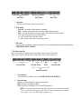
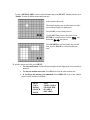
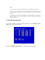
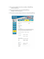
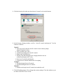
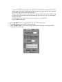
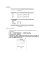
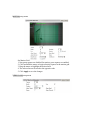
Download Digital View DVR-810 Instruction manual

Transcript
Volume
1
Instruction Manual
EDR810H/EDR810M
EDR410H/EDR410M
EVERFOCUS ELECTRONICS CORPORATION
EDR 810H/810M/410H/410M
Instruction Guide
 2005 EverFocus Electronics Corp
www.everfocus.com
All rights reserved. No part of the contents of this manual may be reproduced or transmitted in any form or by any means
without written permission of the Everfocus Electronics Corporation.
Release Date: April 2009
QuickTime is a registered trademark of the Apple Computer, Inc.
Windows is a registered trademark of the Microsoft Corporation.
Linksys is a registered trademark of the Linksys Corporation.
D-Link is a registered trademark of the D-Link Corporation.
DynDNS is a registered trademark of the DynDNS.org Corporation.
Other product and company names mentioned herein may be the trademarks of their respective owners.
Federal Communication Commission Interference Statement
This equipment has been tested and found to comply with the limits for a Class B digital device,
pursuant to Part 15 of the FCC Rules. These limits are designed to provide reasonable protection
against harmful interference in a residential installation. This equipment generates, uses and can
radiate radio frequency energy and, if not installed and used in accordance with the instructions,
may cause harmful interference to radio communications. However, there is no guarantee that
interference will not occur in a particular installation. If this equipment does cause harmful
interference to radio or television reception, which can be determined by turning the equipment off
and on, the user is encouraged to try to correct the interference by one of the following measures :
• Reorient or relocate the receiving antenna.
• Increase the separation between the equipment and receiver.
• Connect the equipment into an outlet on a circuit different from that to which the receiver is
connected.
• Consult the dealer or an experienced radio/TV technician for help. FCC Caution: Any changes
or modifications not expressly approved by the party responsible for compliance could void the
users’s authority to operate this equipment. This device complies with Part 15 of the FCC Rules.
Operation is subject to the following two conditions: (1) This device may not cause harmful
interference, and (2) this device must accept any interference received, including interference that
may cause undesired operation. This device and its antenna(s) must not be co-located or operating
in conjunction with any other antenna or transmitter.
TABLE OF CONTENTS
1. PRODUCT OVERVIEW....................................................................................................... 12
1.1 FEATURES ............................................................................................................................ 12
1.2 SPECIFICATIONS ................................................................................................................... 13
1.3 FRONT PANEL KEYPADS ....................................................................................................... 14
1.4 BACK PANEL CONNECTIONS ................................................................................................ 17
1.5 MONITOR DISPLAY .............................................................................................................. 20
2. INSTALLATION .................................................................................................................... 24
2.1 BASIC WIRING INSTRUCTIONS ............................................................................................. 25
2.2 HARD DISK DRIVE INSTALLATION ....................................................................................... 27
2.3 FINAL INSTALL PROCESS ...................................................................................................... 27
2.4 QUICK INSTALLATION GUIDE FOR EDR810M & EDR410M ONLY......................... 28
3. DVR MENU SETUP .............................................................................................................. 33
3.1 TIME/DATE SETUP MENU ..................................................................................................... 34
3.2 CAMERA SETUP MENU ......................................................................................................... 38
3.3 RECORD SETUP MENU ......................................................................................................... 42
3.4 ALARM SETUP MENU ........................................................................................................... 44
3.5 MOTION SETUP MENU ......................................................................................................... 47
3.6 VIDEOLOSS SETUP MENU................................................................................................. 50
3.7 NETWORK SETUP MENU ...................................................................................................... 52
3.7.1 CONFIG .............................................................................................................................. 52
3.7.2 ALARM NETWORK .......................................................................................................... 55
3.7.3 EMAIL................................................................................................................................. 56
3.7.4 PASSWORD........................................................................................................................ 57
3.7.5 WIRELESS.......................................................................................................................... 58
3.7.6 PPPOE.................................................................................................................................. 60
3.7.7 DDNS .................................................................................................................................. 61
3.7.8 GPS ...................................................................................................................................... 63
3.8 SCHEDULE SETUP MENU ...................................................................................................... 64
3.9 DISK SETUP MENU ............................................................................................................... 66
3.10 CONTROL SETUP MENU ..................................................................................................... 68
3.11 WARNING SETUP MENU ..................................................................................................... 70
3.11.1 FAN FAULT....................................................................................................................... 70
3.11.2 HDD TEMP ....................................................................................................................... 71
3.11.3 NO HDD............................................................................................................................. 73
3.11.4 HDD FULL ........................................................................................................................ 74
3.12 SYSTEM SETUP MENU ........................................................................................................ 76
4. RECORDING OVERVIEW.................................................................................................. 79
4.1 INSTANT (N) RECORDING SETUP .......................................................................................... 79
4.2 SCHEDULE RECORDING SETUP ............................................................................................. 80
4.3 EVENT RECORDING SETUP ................................................................................................... 81
5. PLAYBACK OVERVIEW..................................................................................................... 84
5.1 BASIC PLAYBACK ................................................................................................................ 84
5.2 SEARCH PLAYBACK ............................................................................................................. 87
6. COPYING VIDEO ................................................................................................................. 90
6.1 VIEWING A COPIED FILE ...................................................................................................... 92
7. CALL OVERVIEW................................................................................................................ 93
8. SCREEN DISPLAY SETTING & MODE ........................................................................... 94
8.1 MODE BUTTON .................................................................................................................... 95
9. UPGRADE FIRMWARE....................................................................................................... 96
10. NETWORKING OVERVIEW............................................................................................ 97
10.1 INTRODUCTION TO TCP/IP................................................................................................. 97
10.2 SUBNET MASKS ................................................................................................................. 97
10.3 GATEWAY ADDRESS ........................................................................................................... 98
10.4 VIRTUAL PORTS ................................................................................................................. 98
10.5 PRE-INSTALLATION ............................................................................................................ 98
10.6 WHAT TYPE OF NETWORK CONNECTION DO YOU HAVE?.................................................. 100
10.7 SIMPLE ONE TO ONE CONNECTION .................................................................................. 101
10.8 DIRECT HIGH SPEED MODEM CONNECTION..................................................................... 107
10.9 ROUTER OR LAN CONNECTION ....................................................................................... 109
11. LINKSYS PORT FORWARDING.....................................................................................112
12. D-LINK PORT FORWARDING........................................................................................116
13. EVERFOCUS DDNS SETUP............................................................................................ 120
14. VIEWING THROUGH INTERNET EXPLORER......................................................... 122
14.1 SEARCH......................................................................................................................... 128
14.1.1 SEARCH BY TIME .............................................................................................................. 128
14.1.2 SEARCH BY EVENT ......................................................................................................... 129
14.2 PTZ CONTROL.................................................................................................................. 130
14.3 REMOTE ARCHIVE...................................................................................................... 131
14.4 REMOTE CONFIGURATION ................................................................................................ 136
15. INTERFACE SPECIFICATIONS .................................................................................... 143
15.1 TRANSMISSION SETTING .................................................................................................. 143
15.2 REMOTE CONTROL PROTOCOL ......................................................................................... 144
APPENDIX A: REMOTE CONTROL .................................................................................. 147
APPENDIX B: ALARM BOARD CONFIGURATION........................................................ 148
TROUBLESHOOTING........................................................................................................... 150
Safety Warning
WARNING
TO REDUCE RISK OF FIRE OR ELECTRIC SHOCK,
DO NOT EXPOSE THIS APPLIANCE TO RAIN OR MOISTURE.
Press the STOP key to stop playing back.
CAUTION
DO NOT REMOVE COVER. NO USER SERVICEABLE PARTS
INSIDE.
REFER SERVICING TO QUALIFIED SERVICE PERSONNEL.
Note:
This equipment has been tested and found to comply with the limits
for a Class A digital device,
The changes or modifications not expressly approved by the party
responsible for compliance could void the user's authority to operate
the equipment.
Note:
This is a class A product. In a domestic environment this product may
cause radio interference, in which case the user may be required to
take adequate measures.
Notice:
The information in this manual was current when published.
The manufacturer reserves the right to revise and improve its
products.
All specifications are therefore subject to change without notice.
Safety Precautions

Refer all work related to the installation of this product to qualified service
personnel or system installers.

Do not block the ventilation opening or slots on the cover.

Do not drop metallic parts through slots. This could permanently damage the
appliance. Turn the power off immediately and contact qualified service
personnel for service.

Do not attempt to disassemble the appliance. To prevent electric shock, do not
remove screws or covers. There are no user-serviceable parts inside. Contact
qualified service personnel for maintenance. Handle the appliance with care.
Do not strike or shake, as this may damage the appliance.

Do not expose the appliance to water or moisture, not try to operate it in wet
areas. Do take immediate action if the appliance becomes wet. Turn the power
off and refer servicing to qualified service personnel. Moisture may damage
the appliance and also cause electric shock.

Do not use strong or abrasive detergents when cleaning the appliance body.
Use a dry cloth to clean the appliance when it is dirty. When the dirt is hard to
remove, use a mild detergent and wipe gently.

Do not overload outlets and extension cords as this may result in a risk of fire
or electric shock.

Do not operate the appliance beyond its specified temperature, humidity or
power source ratings. Do not use the appliance in an extreme environment
where high temperature or high humidity exists. Use the appliance at
temperature within indoor type DVR for 32oF ~ +104oF and a humidity below
90%. The input power source for this appliance is AC100~240V.
Safety Precautions

Read Instruction
All the safety and operating instructions should be read before the unit is
operated.

Retain Instructions
The safety and operating instructions should be retained for future reference.

Heed Warnings
All warnings on the unit and in the operating instructions should be adhered to.

Follow Instructions
All operating and use instructions should be followed.

Cleaning
Unplug the unit from the outlet before cleaning. Do not use liquid cleaners or
aerosol cleaners. Use a damp cloth for cleaning

Attachments
Do not use attachment not recommended by the product manufacturer as they
may cause hazards.

Water and Moisture
Do not use this unit near water-for example, near a bath tub, wash bowl, kitchen
sink, or laundry tub, in a wet basement, near a swimming pool, in an unprotected
outdoor installation, or any area which is classified as a wet location.

Servicing
Do not attempt to service this unit by yourself as opening or removing covers
may expose you to dangerous voltage or other hazards. Refer all servicing to
qualified service personnel.

Power Cord Protection
Power supply cords should be routed so that they are not likely to be walked on
or pinched by items placed upon or against them, playing particular attention to
cords and plugs, convenience receptacles, and the point where they exit from
the appliance.

Object and Liquid Entry
Never push objects of any kind into this unit through openings as they may touch
dangerous voltage points or short-out parts that could result in a fire or electric
shock. Never spill liquid of any kind on the unit.
Chapter
1
1. Product Overview
EDR810/410 DVRs are the industry’s first full-featured digital video recorder designed specifically for
use within the security industry. EDR810/410 DVRs incorporates all the benefits of digital video
recording, is simple to install, and operates just like a VCR. Highly efficient compression technology
and superior resolution of recorded images make the Digital Video Recorder stand out from the
competition as the best choice for security surveillance.
1.1 Features


















Duplex Operation for Recording & Playback
Built-in MPEG4 Codec with Configurable Quality
Variable Recording Speeds up to 60/50 Images per second for NTSC/PAL
Audio Recording Capabilities
Motion Detection Capabilities
One 3.5” Hard Disk with Hot-Swap Tray for Internal Storage
Ethernet Interface for Remote Network Viewing
Optional Wireless LAN Interface for Data Transmission
RS485 for Remote Control
Shuttle/Jog Dial for Picture-by-Picture or Fast/Slow Viewing
Easy-to-use Control Panel with Common VCR and Multiplexer Functions
On-Screen Menus Operations with Multi-Language Support
Real-Time Live Display for all Cameras
Easy archiving of video and Remote Viewer through USB port
Remote configuration function
Remote Firmware Upgrade function
Motion detection function can be scheduled according to user’s setting
For mobile models (ED810M/410M), GPS data can be sent out to receiver, for user to orientate
the exact position
1.2 Specifications
NTSC or PAL
4/8 camera inputs (BNC), 1Vp-p/75ohm
1 BNC video out (1Vp-p/75ohm) for Main Monitor
Video output
1 BNC video out (1Vp-p/75ohm) for Call Monitor
4 BNC outputs (1Vp-p/75ohm) for Looping (4 Channels only)
Video compression MPEG4
720x240, 720x480 or 360x240 for NTSC
Recording resolution
720x288, 720x576 or 360x288 for PAL
Full, 4, 7, and 9 screen view for Live and Playback
Video display
PIP and 2x2 Zoom for Playback only
4/8 Alarm Inputs
Alarm inputs
1 Alarm Output
Alarm outputs
One Hot-Swappable 3.5” IDE or SATA Hard Disk
Hard disk storage
(2.5” hard disk available for mobile models)
Up to 120/100 Images per second for NTSC/PAL
Recording rate
Video format
Video input
Recording mode
Continuous, Schedule, Event (Motion and Alarm) recording
Playback rate
Playback search
Playback options
Motion detection
Video Loss detection
Event Log
Setup
Up to 60/50 Images per second for NTSC/PAL
By Date/Time or Event (Motion, Video Loss, Alarm)
Play, Pause, Stop, Fast Fwd, Fast Rev, Slow Fwd, Slow Rev
Yes, with configurable detection grid & sensitivity per camera
Yes
Yes
Menu Driven On Screen Display
Front panel keypad with Shuttle/Jog, IR Remote Control,
EKB500 Keyboard (optional)
Built-in real time clock with Watch Dog function and Auto Time
Synchronization through NTP server
12-characters title for each camera
RJ45 connectors for network communication
USB port for flash memory or external DVD drive
9-pin female connector for testing purpose only
for Keyboard or PTZ connection
1 set of stereo inputs, 1 set of stereo outputs
12~24 VDC
Inches: 11.7 (L) x 8.3 (W) x 3.5 (H)
Millimeters: 296.9 (L) x 211.1 (W) x 88.9 (H)
4 kg (approximately 8.8 lbs)
User input device
Timer
Title
Ethernet
Archive
RS-232
RS-485
Audio
Power rate
Dimensions
Weight
Operating
temperature
0oC ~ 40oC (32 ℉~104℉)
1.3 Front Panel Keypads
Keys:
○1 ~ ○8 Channel Key: Press FULL+Channel Key (CH1~CH8) to display video image in the full
screen format; the picture of the corresponding channel will fill the whole screen.
○1 CH1 / REC: Press this key to start instant recording.
○2 CH2 / REV. PLAY: Reverse Play Back.
○3 CH3 / STOP: Press this key to stop recording and playing back.
○4 CH4 / PLAY: Play Back.
○5 CH5 / PAUSE: Press this key to pause the playback picture.
○6 CH6 / SEARCH: Press this key to enter the SEARCH MENU.
○7 CH 7 / COPY: Press this key to enter the COPY MENU. If pressed while in playback mode, it
is also used to bookmark copy time.
○8 CH8 / ENTER: Press this key to enter items, or jump to next subentry in the menu setting.
○9 FULL: Press this key and channel Key at the same time to switch to full screen in both live
mode and play back mode. Press “MODE” to exit full screen.
○10 MODE: Switch PIP (Live only), 4, 7 and 9 displays in Live and Playback modes.
○11 ZOOM: In full screen mode, 2x electronic zoom. Zoom screen can be moved through JOG.
ENTER key changes the direction. Press the zoom key again to switch the electronic zoom off.
In multiscreen mode: Screen adjustment. Use the JOG to adjust the image to the fit the monitor.
ENTER switches between horizontal and vertical adjustment. Press the zoom key again to switch
the screen adjustment off.
○12 SEQ: Press this key to enter the auto sequential switching mode.
○13 SELECT: In multi-screen, press this key to assign cameras to different screens; in single
screen, use it to adjust display properties. In menus, press this key to select certain features.
○14 CALL: Press this key to enter and set up CALL MENU.
○15 DISPLAY: Press this key to switch display of channels and/or status bar.
○16 MENU: Press this key to enter or exit MAIN SETUP MENU or to exit from any submenu.
○17 HDD Lock: Keeps HDD in place and turns on HDD power.
○18 Hard Disk Tray: Hard Disk holder for HDD.
○19 Shuttle and Jog Dial
Shuttle:
In the Playback mode, turn the Shuttle dial to fast forward/rewind
the video.
In the Pause mode, turn the Shuttle dial to slow forward/rewind the
video.
In the event list, turn the Shuttle to change pages.
Jog Dial:
In the Menu mode, turn the Jog dial to change settings and values in
subentries. In the Pause mode, turn the Jog dial to forward/rewind
the video frame by frame.
○20 USB Slot: USB port allows you to archive video files or upgrade the DVR software.
○21 HDD LEDs: LEDs for HDD active power (GREEN) and data reading /writing (YELLOW).
○22 Remote Control: Receiver for IR remote control.
○23 System LEDs: LEDs for system active LAN, ALARM and POWER display.
1.4 Back Panel Connections
Back panel of 810H
Back panel of 810M
Back panel of 410H
Back panel of 410M
POWER
○1
Main Power plug: Connect the DC 12~ 24V power source to adapter for AC 100~ 240V.
○2
Audio IN: Audio input for recording, and it can be set to “YES” or “NO” in the RECORD
SETUP MENU.
Audio OUT: Connect an audio output to a monitor or other device.
MONITOR
○3
MAIN MONITOR: This connector is used for the main monitor display, a number of
different display modes may be selected for viewing.
○4
CALL MONITOR: This connector is used for the call monitor. This monitor can only
display a full screen picture.
VIDEO CONNECTIONS
○5 For EDR810 Series:
VIDEO IN(1~8): BNC video inputs.
For EDR410 Series:
VIDEO IN(1~4): BNC video inputs
VIDEO OUT(1~4): BNC loop-through outputs
ALARM INPUT/OUTPUT
○6 ALM-INPUT: Normal open or normal close type alarm signal inputs.
The Alarm Input can be selected as Normal Open (N.O.), Normal Close (N.C.), N.C. TRANS.,
or N.O, TRANS input in the ALARM SETUP MENU.
When an alarm occurs, alarm recording will automatically start.
ALM-OUTPUT: A built-in relay offers 3 nodes which are ALM-COM (common), ALM-NO
(normal open) and ALM-NC (normal close) for external use. Note: Please check APPENDIX
C to see other available alarm input/output functions.
LAN
○7 LAN Connector: RJ-45 network connection.
RS232
○8 RS232 connector: D-Sub 9-pin connector to RS232 ports for testing purpose ONLY.
RS485
○9 RS485 connector: RJ 45 Connector to cascade/control multi Digital Video Recorders.
Remote
○10 Remote Control: Remote control port allows for an extension wire with an IR receiver instead
of the IR receiver on the front panel.
Note: The IR receiver extension line (10m) must be purchased separately.
Wireless LAN
○11 Antenna: Integrated IEEE 802.11b/g wireless LAN capabilities. The antenna port is for
wireless network antenna use (For EDR 410M and 810M only).
Fan
○12 Fan: Cooling fan.
1.5 Monitor Display
The status information of the cameras or machine will show up, and be located at different places
on the screen.
2. Event sign
1. Channel tag
3. Select sign
4. Play status bar
5. Record status bar
For mobile model only:
6. GPS
orientation
○1 Channel tag: A channel tag indicates the channel name of the screen.
○2 Event sign: Event signals which are small icons with a capital letter and red background show
the events on each screen. There are a total of 6 different signals:
A
Alarm event.
Alarm event shows on a channel if an ALARM is enabled for that camera in the ALARM
SETUP MENU and an alarm is triggered.
M
Motion event.
Motion event only shows up when the camera’s MOTION is enabled in MOTION SETUP
MENU and the camera detects movement.
V
Video loss event.
Video loss event only shows when the camera’s VIDEOLOSS is enabled in VIDEOLOSS
SETUP MENU and the camera signal is lost.
S
Sequence sign.
Sequence sign shows up when the display is in sequence mode.
The last display on the screen has a “*” sign in the top-middle. The S sign will replace the “*” in
the display when sequence occurs.
Note: Sequence cannot be activated when the multi-screen display is showing all cameras.
T
F
Temperature indication.
This shows if the hard drive’s temperature is overheated.
Overheat temperature is determined in HDD TEMPERATURE of WARNING SETUP
MENU.
Fan fail indication.
This shows when the fan fails to work normally. If you get this warning, contact technical
support for assistance.
○3 Select sign: You can assign a camera to a display by pressing SELECT key in live mode.
Dial Jog to move the select sign to the display you would like to change, and then press the desired
channel key from the front panel to move that channel to that screen. Press SELECT again to exit
from this mode.
○4 Play status bar: The play status bar appears in play back mode if the status bar is enabled (see
DISPLAY, 8th item of Front Panel Keypads). There are three parts that will be shown: play date,
play status, and play time.
Play Date
Play Status
Play Time
1. Play date
The date on which the video was recorded.
2. Play status
“PAUSE”, when the video playback is paused.
“P## >” means normal play speed on the displayed disk number;
“P## <“ means normal reverse play speed on the displayed disk number;
“##%” shows the position on the Hard Drive;
“>> x N” means N time fast play speed;
“<< x N” means N time fast reverse play speed.
3. Play time
The play time at which the video is recorded. The time format depends on the setting in the
TIME/DATE SETUP MENU.
○5 Record status bar
The record status bar appears when you enable a status bar on the screen.
There are four parts: current date, record status, event, and current time.
Current Date
Record Status
Event
Current Time
HDD/Fan Status
1.
Current date
The current date which is set in the TIME/DATE SETUP MENU.
2.
Record status
Displays current Hard Drive and record position.
R01: currently recording on Disk 1
16%: currently recording at 16% of total HD position
NOTE: Percentage only indicates the physical point of recording on the Hard
Drive, not the total disk space used. To review the total amount of recording
time, please refer to the Disk Menu (Chapter 3.9)
3.
Event
The current/last event that occurred.
4.
Current time
The current time, which can be set in the TIME/DATE SETUP MENU.
5.
HDD/FAN status
“No Disk”: only shows when no disk is installed or detected.
“No Fan”: only shows when internal fan stops working.
“HDD OT”: only shows if hard drive is over temperature.
○6 GPS orientation
When GPS data is sent out to receiver, the exact position will be located by showing vehicle’s
longitude and latitude.
Chapter
2
2. Installation
The installations described below should be done by qualified service personnel or system
installers.
I) PACKING
Please check accessories in the packing before the installation.
II) SYSTEM FLOORPLAN
Please refer to the following diagrams for the system connections.
Note: Monitor and Camera must be purchased separately.
Diagram 2.1
2.1 Basic Wiring Instructions
Please refer to diagram 2.1 to assist you with this portion of the installation.
1. Power
Connect the power source or adapter into the power socket.
2. Cameras
Connect each cameras video output to the video inputs on the digital video recorder.
Note: At least one camera must be connected before the system is running for the auto detection of
video standard to take effect.
3. Audio Input
The camera audio output or Microphone is connected to the audio input terminal at the rear panel.
4. Audio Output
Connect the speaker or other audio listening devices to the audio output terminal on the back of the
digital video recorder.
5. Ethernet
The digital video recorder may be viewed from a PC via the LAN connector using a RJ45 Ethernet
cable.
6. RS485
The digital video recorder can be controlled from an EKB500 keyboard via RS485.
Note: This can be done using a RJ45-to-serial cable.
7. Main Monitor
Connect a monitor to the main monitor output connector. The main monitor displays live or
recorded cameras in any available format.
Note: The main monitor must be connected in order to make configuration changes, enter the main
menu, or do a playback at the machine.
8. Call Monitors
Connect the call monitor output connectors to a call monitor. The call monitor display selected live
cameras in full screen format.
Note: The call monitor will only display one full screen camera at a time.
2.2 Hard Disk Drive Installation
The first step in installing the hard drive is to insert the hard drive sleeve into the machine. The hard
disk drive default setting is initially set to master. The second step is to insert the key provided and turn
the tray key to the lock position. If this process is ignored the hard disk drive will not be detected.
 Note: If the Hard Disk Drive is not locked in with the key, HDD LED will not light
up and the DVR will not go into record mode. This is because the Hard Drive is
not being recognized.
 Note: After powering on the DVR, it will start to load system. It takes a while to
complete loading system, during this time, please do not install or remove the hard
disk. No action is recommended while the machine is loading system.
Diagram 2.2 shows 3.5“ Hard Drive
2.3 Final Install Process
Once you have completed the basic wiring installation and the hard disk drive installation you are ready
to turn on the DVR. Simply plug the power source you installed earlier. The POWER LED lights will
light up if power is normal. The next step is to set up the menu options for the DVR.
2.4 QUICK INSTALLATION GUIDE FOR EDR810M & EDR410M
ONLY
The EDR810M & EDR410M are the full-featured digital video recorders designed specifically
for use in mobile applications. Please refer to the following Quick Installation Guide for installing
EDR810M or EDR410M into mobile applications such as buses, cars and police cruisers.

The DVR can be mounted horizontally (suspend or support mounted).
Support
Interface
EDR410M
EDR410M
Suspend
Interface
Show all the possible ways to mount the DVR.
Use the two Z-brackets supplied to mount it in any ways shown.

EDSR40
0M
Support
EDSR400M
Quick Installation Guide
Suspend
Unpack Everything
Make sure you have everything you need before you begin the installation.

Equipment Required
The following tools may help you to complete the installation:

• Drill
• Screwdrivers
• Wire cutters

Choosing the Location Choose a location for installation that:
• Provides convenient access for installing or removing the hard drive
• Allows air to flow around the fan vents. Inadequate or improper air flow can impede proper
operation of the unit
Avoid any location for installation:
• That is subject to high vibration
• That is subject to high sunlight levels
• That is subject to drenched of the rain
• Where passengers can interfere with unit
• Next to a heater duct
The following table lists the recommended location options.
Location
Convenient operation
Easy to install
Low vibration
Good air flow
Bottom of glove box- horizontal mount
Yes
Yes
Yes
Yes
Bottom of passenger seat next to the driver
NO
Yes
Yes
Yes
Underneath bulkhead-horizontal mount
Yes
Yes
NO
Yes
Front of bulkhead-horizontal mount
Yes
Yes
Yes
Yes
Beside deriver seat-horizontal mount
Yes
Yes
Yes
Yes
Caution: Do not install the DVR on the floor or on the transmission access hatch. These
locations have the highest levels of vibration and may be subject to water damage.

Possible Installation Locations Inside the Automobile Vehicle: Truck
Glove box (inside or underneath)
Drive seat (between seat and wall) or Passenger seat (underneath)
(Users are suggested to use “support” for mounting option)

Show the wiring on the wiring harness that connects to the electrical system.
(24 V)
(5 A)

Possible Installation Locations Inside the Automobile Vehicle: TOYOTA CAMRY
Glove box (inside or underneath)
Trunk (Users are suggested to use
“suspend” for mounting option)
Passenger seat (underneath)
Drive seat (between seat and wall)

Show the wiring on the wiring harness that connects to the electrical system.
Installing the Camera(s) and Monitor
The DVR is typically connected to one camera installed inside the car. Other camera(s) can also
be installed in different locations (for example, use the waterproof camera to the outside of
vehicle). For installation procedure, please refer to the guide that came with the camera(s) you
purchased.
The Monitor power supply connects from the Automotive adapter (cigarette plug)
Monitor and cameras must be purchased separately.

LCD Monitor
LCD Monitor
Connect the Camera(s)Connect the power connector from the camera(s) harness into the
CAMERA POWER OUT jack on the back panel of the DVR.
Connect the primary camera(s) video connector to the CAMERA INPUT and the audio connector
to the AUDIO INPUT in the back panel.
Adjust the camera(s). After the camera is installed, connect a monitor directly to the camera and
observe the image.
Make any adjustment if necessary.

Chapter
3
3. DVR Menu Setup
Assuming you have completed the first two chapters of this manual, you are now ready to begin setting
up the digital video recorder. The following chapter will walk you through the detailed DVR Menu step
by step and how to set the DVR for your specific application. To begin this process, press the MENU
key. Once inside the Main Menu you will find there are 12 setup option pages as follows.
Press the MENU key to enter or exit the MAIN SETUP MENU.
Press the MENU key in any sub-menu to go back to previous screen.
MENU
Dial the Jog clockwise or counterclockwise to scroll through the MAIN MENU
options or to change subentry values.
Press the ENTER key to go to the next subentry in a menu setting.
Press the DISPLAY key to go to the previous subentry in a menu setting.
Diagram 3.1
3.1 Time/Date Setup Menu
Diagram 3.2
Diagram 3.2 is a screenshot of the TIME/DATE SETUP MENU. This menu is used to set up the
correct time and date for your region of the world. You are able to setup daylight savings as well as
synch it with an internet based time server. In the TIME/DATE SETUP MENU the following fields
are defined as follows:
1. TIME FORMAT: This field represents the time format on the DVR. You can select between 12
HOUR and 24 HOUR format.
2. TIME: This field represents the current time on the DVR. To change this, turn the Jog Dial on the
DVR.
The Time is represented as follows:
Hour: 00~23 (1 ~ 12 if TIME FORMAT is 12 HOUR): Minute: 00~59: Second: 00~59
3. DATE FORMAT: This field represents the date format on the DVR. To change this, simply use
the Jog Dial on the DVR. There are three date formats to select from: YYYY-MM-DD,
MM-DD-YYYY and DD-MM-YYYY.
4. DATE: This field represents the date on the DVR. To change this, turn the Jog Dial on the DVR.
The day of the week automatically adjusts according to the other settings.
By default, the date is represented as follows:
Year: 2000~2037 / Month: 01~12 / Date: 01~31 (Day of Week)
5. DAYLIGHT SAVING: This field represents the daylight savings on the DVR. To change this,
simply use the Jog Dial on the DVR. Select “ON” or “OFF” to enable or disable daylight saving
time function. This feature must be disabled in order to make any changes to the start and end
times.
6. START TIME: To set the beginning of daylight saving time.
To set the start month of daylight saving time: Dial the jog to set the start month.
JAN
FEB
MAR
APR
MAY
JUN
JUL
AUG
SEP
OCT
NOV
DEC
To set the start week of daylight saving time: Dial the jog to set the start week.
1 ST
2 ND
3 RD
4 TH
LAST
To set the start date of daylight saving time: Dial the jog to set the start date.
SUN
MON
TUE
WED
THU
FRI
SAT
To set the starting time change of daylight saving time: Choose the “FROM” time and
“TO” time when daylight savings starts.
7.
END TIME: To set the end of daylight saving.
To set the end month of daylight saving time: Dial the jog to set the end month.
JAN
FEB
MAR
APR
MAY
JUN
JUL
AUG
SEP
OCT
NOV
DEC
To set the end week of daylight saving time: Dial the jog to set the end week.
1 ST
2 ND
3 RD
4 TH
LAST
To set the end date of daylight saving time: Dial the jog to set the end date.
SUN
MON
TUE
WED
THU
FRI
SAT
To set the ending time change of daylight saving time: Choose the “FROM” time and “TO”
time when daylight saving time ends
8. TIME SYNCHRONIZE: Select “ON” or “OFF” to enable or disable time synchronize which
will automatically update the DVR’s time when connected to a network. To change this, simply use
the Jog Dial on the DVR.
9.
TIME SERVER: You can set the time server address that the DVR connects to for time
synchronize. To determine the IP address of NTP Server, please follow these steps:
a) Go to a PC that is connected to the internet.
b) Click on “START” -> “RUN” -> type “cmd” and press “OK”.
c) In the Dos Prompt, type “ping pool.ntp.org” to find out the IP address of an NTP Server.
Diagram 3.3
9. TIME ZONE: You can set the time zone that the DVR adjusts to when updating from the time
server.
Atlantic Daylight Time subtract 3 hours from GMT
Atlantic Standard Time subtract 4 hours from GMT
Eastern Daylight Time subtract 4 hours from GMT
Eastern Standard Time subtract 5 hours from GMT
Central Daylight Time subtract 5 hours from GMT
Central Standard Time subtract 6 hours from GMT
Mountain Daylight Time subtract 6 hours from GMT
Mountain Standard Time subtract 7 hours from GMT
Pacific Daylight Time subtract 7 hours from GMT
Pacific Standard Time subtract 8 hours from GMT
Alaska Daylight Time subtract 8 hours from GMT
Alaska Standard Time subtract 9 hours from GMT
Hawaii-Aleutian Daylight Time subtract 9 hours from GMT
Hawaii-Aleutian Standard Time subtract 10 hours from GMT
11. TIME UPDATE BY: Once you enable the TIME SYNCHRONIZE, you can select the
synchronization frequency by:
DAY
WEEK
MONTH
3.2 Camera Setup Menu
Diagram 3.4
Diagram 3.4 is a screen shot of the CAMERA SETUP MENU. This menu will walk you through
setting up the Camera Recording Speeds, Camera Titles, PTZ ID, covert modes, and recording quality.
In the CAMERA SETUP MENU the following fields are defined as:
1. TITLE: The title setting allows you to assign a title to each camera input. Each channel supports a
title with up to 12 characters. Press Enter to move to each character and use the Jog Dial to change
the value. The available alphanumeric characters are:
0,1,2,3,4,5,6,7,8,9,
A,B,C,D,E,F,G,H,I,J,K,L,M,N,O,P,Q,R,S,T,U,V,W,X,Y,Z,
( ) . , + - / and an empty space.
2. PTZ ID: Select PTZ ID/Address from 001~255 or OFF. OFF is the same as 000. The default value
is 10+N where N is camera’s number. This ID must be the same as the ID used in PTZ Dip Switch.
To change this, simply use the Jog Dial on the DVR.
3. INSTALL/COVERT: Select “ON” to enable a camera, and “OFF” to disable it. All recording
must be stopped before making changes to INSTALL. To take full advantage of the DVR’s
recording ability, switch any unused Camera Ports to OFF in this section. For COVERT, select
“ON” to cover a camera, and disable the screen in live mode. However, the image is still recorded,
and can be played back by any user that has playback right. The covert channels will not show up
in the sequence mode. To make changes, simply use the Jog Dial on the DVR.
4. SEQ (MAIN/CALL): Set the number of seconds a camera is displayed in sequence. The first
number is for sequence on the Main Monitor, the second number is for sequence on Call Monitor.
5. REC QUALITY: Select an image quality for recording. There are six different qualities available.
A higher image quality uses more HDD space. To change this, simply use the Jog Dial on the
DVR. The approximate space needed per second is listed below:
720x480
Average size
per image
Video Source
Simple:
Complex:
LOWER:
8.04KB
12.33KB
LOW:
8.42KB
13.7KB
BASIC:
10.15KB
16.72KB
STANDARD:
11.86KB
19.56KB
HIGH:
14.72KB
24.63KB
SUPERIOR:
18.60KB
30.05KB
Video Source
Simple:
Complex:
LOWER:
3.53KB
7.82KB
LOW:
3.87KB
8.36KB
BASIC:
4.21KB
8.9KB
STANDARD:
4.92KB
9.54KB
HIGH:
5.62KB
10.17KB
SUPERIOR:
6.41KB
12.89KB
Video Source
Simple:
Complex:
LOWER:
1.76KB
4.56KB
LOW:
1.87KB
4.87KB
BASIC:
1.97KB
5.46KB
STANDARD:
2.38KB
6.51KB
HIGH:
2.67KB
7.08KB
SUPERIOR:
3.63KB
9.02KB
720x240
Average size
per image
360x240
Average size
per image
Note: “Simple” refers to very few changes occurring during recording; “Complex” means the
whole image is constantly changing. Since the compression ratio of MPEG4 fully depends on the
variation and complexity of the recorded video, the table above is for reference only.
6. REC SPEED & ACTION:
TP: Scheduled recording time 1~8 which can be set in the SCHEDULE SETUP MENU. “N” is
the normal recording time, which is activated by pressing the Record button. If you have set a Time
Period in Schedule Setup Menu, then there will be a star sign (*) beside that TP in Camera Setup
Menu.
NORMAL: Normal record speed up to 15 IPS (images per second). The default normal record
speed is 1 IPS. EDR810/410 will adjust to the maximum recording speed by calculating the total
installed cameras that have been enabled in the CAMERA SETUP MENU.
EVENT: Event record speed (Images per second) up to 30 IPS or “OFF”.
Note: In order to activate a new record speed, you need to disable all current record actions and
then turn them back on.
ACTION
Set “ON” to activate motion action on a selected Time Period.
Set “OFF” to disable motion action on a selected Time Period.
This setting correlates closely with Motion Setup. If motion setting is disabled, motion detection
will not function regardless if TP (Time Period) Action in Camera Setup Menu is ON or OFF.
However, if Motion setting is enabled, then motion detection function works depending on
Action setting in Camera Setup Menu. All motion actions (including buzzer, relay, network alarm,
e-mail and log) will be triggered if they are enabled in Motion Setup Menu as long as Action is
“ON” for the TP (Time Period) you have set. If you do not wish to have motion detected for a
specific time, set Action “OFF” for that Time Period. This function gives you flexibility to set the
motion detection feature ON or OFF for different Time Periods.
7. SUMMARY:
Diagram 3.5
Dial Jog to change items in the SUMMARY table.
All cameras’ statuses are shown in the SUMMARY table. The table is for checking camera overall
statuses only, not for changing them.
Note: The SUMMARY table also exists in ALARM, MOTION and VLOSS SETUP MENU. All of these
SUMMARY tables are also for checking particular overall statuses, not for changing them.
8. Copy camera’s setting from a camera to other cameras: In order to copy the setting from a
camera to other cameras, we provide a setting copy function. Press MENU when you finish setting up a
camera, and then press COPY. The word “COPIED” will show up in the top right corner of the
screen, and it means the settings have been copied. Dial the Jog to the camera you would like to copy
to, and then press SEARCH. The settings of the first camera will be copied to the next one, and
“PASTED” will show up in the top right corner.
NOTE: TITLE, PTZ ID, and INSTALL/COVERT cannot be copied. These 3 options need to be set
independently.
3.3 Record Setup Menu
Diagram 3.6
Diagram 3.6 is a screen shot of the RECORD SETUP MENU. This menu is for setting up the
options for recording. In the RECORD SETUP MENU the following fields are defined as
follows:
1. RECORD AUDIO:
YES: Audio will be recorded when machine is recording and a microphone is connected.
NO: Audio will not be recorded when machine is recording.
2. TIME STAMP:
ON: The time stamp will show on both the live and recorded video.
OFF: The time stamp will not show on the live or recorded video.
3. TIME STAMP POSITION:
BOTTOM: The time stamp will show on the bottom.
TOP: The time stamp will show on the top.
4. WATER MARK:
ON: Recording is overlaid by a visible watermark (“W”).
OFF: No watermark.
5.
RESOLUTION: The resolutions for NTSC are 720x480, 720x240 and 360x240; the default
value is 720x240. The resolutions for PAL are 720x576, 720x288 and 360x288; the default value
is 720x288.
NOTE: The resolution determines the maximum record speed supported by the DVR.
NTSC
720x480 = 30 IPS (this IPS value is divided by the amount of cameras installed)
720x240 = 60 IPS (this IPS value is divided by the amount of cameras installed)
360x240 = 120 IPS (this IPS value is divided by the amount of cameras installed)
6. RECORD MODE:
REWRITE: Continue recording. Disk will begin overwriting if it is full.
STOP: Stop recording when disk is full.
7. AUTOWRITE WITHIN: You can set DVR to automatically overwrite after the selected
number of days. If you do not wish to use this function, simply select “0”.
8.
PRE-ALARM RECORDING
Select “YES” to enable pre-alarm recording function. Select “NO” to disable pre-alarm recording
function.
9.
RELAY OUT
By selecting “1”, user can easily identify whether DVR is recording or not if relay output is
connected to a signaling device. Select “NONE” if you do not wish to identify recording status.
3.4 Alarm Setup Menu
Diagram 3.7
Diagram 3.7 is a screen shot of the ALARM SETUP MENU. An alarm is defined as an electrical,
electronic, or mechanical device that sends an alert by means of a signal. In this case the signal
triggers the recorder to start recording the alarmed event. This menu contains all the alarm operations
and options needed to successfully set up an alarm recording. In the ALARM SETUP MENU the
following fields are defined as:
1. ALARM: This field is to turn alarm recording on or off. The Default from the factory is set to
Enable. To change this, simply use the Jog Dial on the DVR.
ENABLE: Enable alarm detection.
DISABLE: Disable alarm detection.
2. ALARM TYPE: This field is to set the type of alarm connection. The Default from the factory is
set to N.O. To change this, simply use the Jog Dial on the DVR.
N. O.: Normal Open alarm.
N. C.: Normal Close alarm.
N.O. Trans.: When the alarm is triggered, buzzer starts to function no matter how long the alarm
duration is set until you set it back to N.O.
N.C. Trans.: When the alarm is triggered, buzzer starts to function no matter how long the alarm
duration is set until you set it back to N.C.
3. LOG:
ON: Select ON if you wish to record Alarm Events in the Log.
OFF: Select OFF if you do not wish to record Alarm Events in the Log.
4. ACTIVE CAMERA: This field is to activate camera you want to have the alarm enabled too.
For example if you had an external motion detector on camera one you would set this option to
camera one. The Default from the factory is set to on. To change this, simply use the Jog Dial on
the DVR.
Active camera setting, from camera 01~08. You can set the camera which corresponds to
the place where the alarm is located.
Note: The recording camera number in an event depends on the alarm number, and the active
camera images will not be recorded. Example: You assign camera 3 as the active camera to
alarm 1. When the alarm 1 is triggered, camera 3 will be displayed and camera 1 will be
recorded.
5. PTZ PRESET: Select PTZ PRESET from “001” to “255”, so that when Alarm occurs, speed
dome will turn to this preset position for event recording. This function improves surveillance
quality of an alarm event. If you wish to disable this function, please simply select “OFF”.
6. DURATION:
1~99 SEC: The amount of time alarm recording, screen change, buzzer and output contact will
last. Adjustable from 1 ~ 99 seconds.
TRANSPARENT: Continuous recording, screen change, buzzer, and output contact for an alarm
event.
7. ALARM OUTPUT: This will transmit a signal to another device. The setting of alarms are
NONE = not activated, 1 = output signal 1 transmitted.
8. ALARM EMAIL:
YES: Send an email when an alarm occurs.
NO: Do not send an email when an alarm occurs.
The email address and e-mail server can be set in the NETWORK SETUP MENU.
9. BUZZER: Audible alarm buzzer.
ENABLE: To enable an alarm buzzer.
DISABLE: To disable an alarm buzzer.
10. ALARM NETWORK:
YES: Enable alarm network.
NO: Disable alarm network.
11. MAIN MON: Display on a main monitor when an alarm occurs.
NO CHANGE: No change on the display in the main monitor when an alarm occurs.
FULLSCREEN: A full screen of the active camera will display when an alarm occurs.
12. CALL MON: Display on a call monitor when an alarm occurs.
NO CHANGE: No change on the display in the main monitor when an alarm occurs.
CAMERA 1~8: Display the active camera in full screen mode to the call monitor.
13. SUMMARY: Dial Jog to change items in the SUMMARY table. All alarm’s statuses are shown
in SUMMARY tables. These tables are for checking alarm overall statuses, but not for changing
them.
Note: Please check APPENDIX B to see other available alarm input / output functions.
3.5 Motion Setup Menu
Diagram 3.8
Diagram 3.8 is a screen shot of the MOTION SETUP MENU. We define motion as a change of
pixilation in the field of view, which is detected by the digital video recorder, and triggering the
recorder to start recording. Motion is also considered an event. This menu is for setting up the digital
recorder for motion recording on a per camera basis. In the MOTION SETUP MENU the following
fields are defined as follows:
1. MOTION: This field is to turn motion recording on or off. The Default from the factory is set to
off or disabled. To change this, simply use the Jog Dial on the DVR.
ENABLE: Enable motion detection.
DISABLE: Disable motion detection.
Note: Motion only works in live and playback modes. It is invalid while in menus.
2. SENSITIVITY: The sensitivity allows users to adjust to a suitable motion detection sensitivity.
There are 10 sensitivities available; level 1 is the lowest, and level 10 is the highest. The default is 7.
To change this, simply use the Jog Dial on the DVR.
3. LOG:
ON: Select ON if you wish to record Motion Events in the Log.
OFF: Select OFF if you do not wish to record Motion Events in the Log.
4. DURATION: The amount of time a motion event will record - from 1 sec to 99 seconds. The
default value is 5 seconds. To change this, simply use the Jog Dial on the DVR.
5. ALARM OUTPUT: This will transmit a signal to another device. The setting of alarms are
NONE = not activated, 1 = output signal 1 transmitted. To change this, simply use the Jog Dial
on the DVR.
6. ALARM EMAIL:
YES: Send an email when motion occurs.
NO: Do not send an email when motion occurs.
The email address and e-mail server can be set in the NETWORK SETUP MENU.
7. ALARM NETWORK:
YES: Enable alarm network when motion occurs.
NO: Disable alarm network when motion occurs.
8.
BUZZER: Audible buzzer when motion is detected.
ENABLE: To enable a motion buzzer.
DISABLE: To disable a motion buzzer.
9.
MOTION DELAY:
Select motion delay time from 0~7 level.
10. MAIN MON: Display on a main monitor when an alarm occurs.
NO CHANGE: No change on the display in the main monitor when a motion occurs.
FULLSCREEN: A full screen of the active camera will display when motion occurs.
11. CALL MON: Display on a call monitor when motion occurs.
NO CHANGE: No change on the display in the main monitor when motion occurs.
CAMERA 1~8: Display the active camera in full screen mode to the call monitor.
12. SUMMARY: Dial Jog to scroll through options in the SUMMARY table. All alarm’s statuses
are shown in SUMMARY tables. These tables are for checking alarm overall statuses, but not
for changing them.
To edit a MOTION AREA, enter a desired channel and press SELECT. Motion must be set to
“Enable” in order to edit the motion detection area.
In the motion edit mode:
The default motion area of each camera is entire
screen which displays in light green.
Press COPY to start setting an area.
Use the JOG Dial to move the cursor. Press
ENTER to switch between vertical
and
horizontal
movement.
Press SEARCH to end and enable the selected
area, or press PAUSE to end and disable the
area.
To quit the motion area edit, press MENU.
 To test a motion area: Grids will turn into light red from light green when a motion is
detected.

To clear the motion entire area: Press PLAY to clear the entire motion area.
 If you forget the motion grid commands: Press DISPLAY to get a hint window
(shows below) in motion edit mode.
MENU
COPY
ENTER
SEARCH
PAUSE
EXIT
SELECT AREA
- CHANGE DIR
- ON AREA
- OFF AREA
-
3.6 VIDEOLOSS Setup Menu
Diagram 3.9
Diagram 3.9 is a screen shot of the VIDEOLOSS SETUP MENU. VIDEOLOSS event is caused
when no video signal input is detected on a channel. Usually it happens when the camera loses
power or the camera fails. In the VIDEOLOSS SETUP MENU the following fields are defined
as follows:
1. VIDEOLOSS:
ENABLE: Enable video loss detection.
DISABLE: Disable video loss detection.
2. LOG:
ON: Select ON if you wish to record Video Loss Events in the Log.
OFF: Select OFF if you do not wish to record Video Loss Events in the Log.
3. DURATION: The amount of time a Video loss event will record - from 1 sec to 99 seconds. The
default value is 5 seconds. To change this, simply use the Jog Dial on the DVR.
4. ALARM OUTPUT: This will transmit a signal to another device. The setting of alarms are
NONE = not activated, 1 = output signal 1 transmitted. To change this, simply use the Jog Dial
on the DVR.
5. ALARM EMAIL: Select “YES” for sending an email when video loss occurs. The email address
can be set in the NETWORK SETUP MENU.
6. BUZZER: Audible alarm buzzer.
ENABLE: To enable a video loss buzzer.
DISABLE: To disable a video loss buzzer.
7. ALARM NETWORK:
YES: Enable alarm network.
NO: Disable alarm network.
8. SUMMARY: All video loss’s statuses are shown in SUMMARY tables. These tables are for
checking video loss overall statuses, but not for changing them.
3.7 Network Setup Menu
Diagram 3.10
Diagram 3.10 is a screen shot of the NETWORK SETUP MENU. This menu is for setting up the
configurations for networking to the DVR. There are 6 subentries that are CONFIG, ALARM,
EMAIL, PASSWORD, PPPoE and DDNS in the NETWORK SETUP MENU. Mobile units will
also have the WIRELESS and GPS features available. Please refer to the Networking Chapter of this
manual to fully understand how to setup your network for this DVR. In the Network Setting Menu the
following fields are defined as follows:
Note: Since every Network Configuration is different, please contact your Network Administrator
or ISP for details on how to assign those IP addresses and port numbers.
3.7.1 CONFIG
In the CONFIG of the NETWORK SETUP MENU, we define:
1.
IP CONFIG:
FIXED IP: User can manually set the IP address for network connection.
DHCP: DHCP server in LAN will automatically provide the IP address for network connection.
When you choose this option, the numbers will be faded out.
PPPoE: This is a DSL connection application. ISP will ask user to input user name and
password. When you choose this option, please configure settings in the PPPoE options first.
2.
IP Address
This field shows the current IP Address for the DVR. A Fixed IP address does not change and
must be set manually. To change this, simply use the Jog Dial on the DVR. When DHCP is
selected, DHCP server will assign this value automatically.
Note: The addresses in the machine are for our own testing you should apply your own addresses
to comply with your network. Refer to Networking Chapter for more details.
3.
SUBNET MASK
This field is to set the subnet mask for your network so as the DVR will be recognized within the
network. Example: 255.255.255.000. To change this, simply use the Jog Dial on the DVR. When
DHCP is selected, the DHCP server will assign this value automatically.
4.
GATEWAY
This field is to set the gateway for your network so the DVR will be recognized within the
network. To change this, simply use the Jog Dial on the DVR. When DHCP is selected, the
DHCP server will assign this value automatically.
5.
DNS SERVER
This field is to set the DNS server for your network so the DVR will be recognized within the
network. To change this, simply use the Jog Dial on the DVR. When DHCP is selected, the
DHCP server will assign this value automatically.
6.
REMOTE RELAY CONTROL:
YES: By selecting YES, system will accept remote command of relay control.
NO: By selecting NO, system will refuse remote command of relay control.
7.
HTTP PORT
The default port number is 80. User can change it to different port number for HTTP/WEB
communication between DVR and client PC.
8.
CONTROL PORT
The default port number is 1600. User can change it to different port number for controlling login
between DVR and client PC.
9.
DATA PORT
The default data transmitting port number is 37260. User can change it to different port number
for data transfer between DVR and client PC.
Note: If you wish to have multiple users log into the DVR, please open a range of ports on your
router. For example if you want to allow 4 clients to login through the default port 37260, you
should open the port range 37260-37263 on your router.
10.
BW CONTROL
This configuration allows user to control the bandwidth of DVR.
11.
MAC ADDR
This field is for those Internet service providers or Network administrators who require a MAC
address of the network card of the DVR. This option cannot be changed.
3.7.2 ALARM NETWORK
DVR can send out Alarm message to an Alarm Server. This function is reserved to work with our
Control Management System – PowerCon 4. In the ALARM of the NETWORK SETUP MENU,
we define:
Diagram 3.11
1. PROTOCOL: Select which communication protocol with Alarm servers or Alarm receiving
clients.
TCP: communicate with client via TCP protocol.
UDP: communicate with client via UDP protocol
2. PORT NUMBER: setting the communication port with Alarm server. The default is 1600.
3. UNIQUE ID: setting the ID number of your DVR to Alarm server.
4. SERVER 1: assign the IP address of Alarm server 1.
5. SERVER 2: assign the IP address of Alarm server 2.
6. SERVER 3: assign the IP address of Alarm server 3.
3.7.3 EMAIL
In the EMAIL of the NETWORK SETUP MENU, we define:
Diagram 3.12
1. SMTP SERVER
Assign the SMTP (e-mail) server’s name.
Note: For more reliable email service, use the server’s IP address.
2. PORT NUMBER
Assign the port number for SMTP server. The default port is 25.
3. AUTHENTICATION
Select “YES”, if the SMTP server requires Authentication (user name / password)
4. USER
Input the login user ID if the SMTP server requires Authentication.
5. PASSWD
Input the password if the SMTP server requires Authentication.
6. RECEIV. EMAIL ADDR
Input the e-mail address for receiving e-mail messages when the EVENT is enabled and triggered.
Example: In Motion Setup Menu, if the “EMAIL/NETWORK” is set to “YES”, this e-mail address
will receive a message and a still image (in “ARV” format) from the DVR when Motion is
triggered. This “ARV” file can be played back by opening “DVRViewer.exe” which can be
downloaded from the DVR’s Network Viewer or from the Copy Menu.
7. SENDER EMAIL ADDR
Input sender’s e-mail address, so that receiver can recognize the sender when an event message is
sent out.
3.7.4 PASSWORD
In the PASSWORD of the NETWORK SETUP MENU, we define:
Diagram 3.13
Name/Password/Level: This category is to set up the users that will log into the network. Please
remember that this portion of the Network setting menu is set up in column format.
The default User Name = admin
The default Password = 11111111 (only numeric)
There are 3 level types:
1. Admin: User has all the rights including viewing live video, performing a search, playback,
archiving video, controlling the PTZ camera (if one is connected), and remote configuration.
2. Play: User can view live video, playback, and archive, but does not have access to PTZ control
or remote configuration.
3. Live: Allows user only to view live video.
3.7.5 WIRELESS
In the WIRELESS of the NETWORK SETUP MENU, we define:
Diagram 3.14
1. DHCP: Enable or disable the Dynamic Host Communication Protocol.
YES: Enable DHCP service.
NO: Disable DHCP service.
2. IP ADDRESS: Assign an IP address for this unit, for example: 192.168.010.200
When DHCP is YES, the DHCP server will assign this value automatically.
3. SUBNET MASK: Assign a subnet mask of the network for this unit, for example:
255.255.255.0. When DHCP is YES, the DHCP server will assign this value automatically.
4. GATEWAY: Assign a default gateway for this unit, for example: 192.168.010.001
When DHCP is YES, the DHCP server will assign this value automatically.
5. DNS SERVER: Assign a DNS server for this unit, for example: 168.195.001.001
When DHCP is YES, the DHCP server will assign this value automatically.
6. MODE: STA stands for Station (cannot be changed)
7. AUTHENTIFICATION:
Select from OPEN/NONE, OPEN/WEP, SHARED/NONE, SHARED/WEP or
WPAPSK/TKIP.
Open: no need of shared key.
Shared: need shared key.
WEP: uses encrypted data transmission. Wireless networks broadcast messages using radio and
are thus more susceptible to eavesdropping than wired networks.
WPAPSK: Each user must enter a passphrase to access the network.
TKIP: Randomizes the key used for each packet. The key is created by mixing together a base
key, the MAC address of the transmitting station, and the serial number for the packet. The
mixing operation is designed to put a minimum demand on the stations and access points, yet
have enough strength so that it cannot easily be broken.
8. AP ESSIP: Enter the SSIP of Access Point to be connected.
9. KEY: Password of the Access Point.
10. NETWORK TYPE:
Select from INFRA (infrastructure) and ADHOC for network type.
3.7.6 PPPoE
In the PPPoE of the NETWORK SETUP MENU, we define:
Diagram 3.15
1.
2.
3.
4.
USER: User name that is provided by ISP for PPPoE connection
PASSWD: Password that is provided by ISP for PPPoE connection
PRIMARY DNS: IP address of DNS server that is provided by ISP.
SECONDARY DNS: If your ISP provides a secondary DNS address, please set it here.
NOTE:
If you change IP CONFIG to PPPoE before completing all settings in the PPPoE Setup Menu,
then the PPPoE function will not work. Make sure you configure the PPPoE settings completely
before making this change.
3.7.7 DDNS
In DDNS of the NETWORK SETUP MENU, we define:
Diagram 3.16
1. SERVER: DDNS provider.
2. USER: User name of the account.
3. PASSWD: Password of the account.
4. RECORD ID: Record ID.
5. FQDN: The domain name of this account.
For example: A user had applied for a DDNS account from Http://www.dyndns.org.
User name: TEST
Password: TEST
Domain name ethne.dyndns.org.
Users can connect to DVR that uses dynamic IP address by entering the domain name
“ethin.dyndns.org” in IE browser.
They don’t have to know the IP address.
NOTE: This domain name is only an example. The DDNS account that the user applies will
differ from this example.
EVERFOCUS DDNS
If you are using software 1.6.2 or higher, you can use the EverFocus DDNS server.
1. First, go to the website http://everfocusddns.com and check for an available name
2. In the DDNS Menu, choose “EverFocus DDNS” for Server
3. For Hostname, put the name you chose from the DDNS website.
4. Press the SELECT button to synchronize with the server. You should see the word
“Success” at the bottom of the screen. If you get a message saying “Could Not Find
Server”, double-check your network settings and try again.
5. You should now be able to connect by typing in the host name you created.
Example: http://hostname.everfocusddns.com
3.7.8 GPS
In GPS of the NETWORK SETUP MENU, we define:
Diagram 3.17
1. AUTOMATIC GPS
2. TRANSMISSION:
YES: select YES to enable transmission
NO: select NO to disable transmission
3. UNIQUE ID: Input GPS Unique ID.
4. GPS TRANSMISSION CYCLE TIME IN SECONDS:
Enter GPS transmission cycle time in seconds.
5. GPS RECEIVER IP ADDRESS
Set GPS receiver’s IP address.
6. PROTOCOL:
Select protocol from TCP and UDP.
7. PORT NUMBER: GPS port number.
3.8 Schedule Setup Menu
Diagram 3.17
Diagram 3.17 is a screen shot of the SCHEDULE SETUP MENU. In this menu you can set a unique
timer any day of the week to start recording from a specified start time to an end time. You will notice
TP (time period) 1~8, which is also seen in the Camera Menu. In the SCHEDULE SETUP MENU
the following fields are defined as:
1.
DAY: This field represents the day of the week you wish to set the timer record for. It is set to
DLY as default. You may choose from Mon-Sun as well as WDAY (weekday), WEND
(weekend), or DLY (daily). To change this, simply use the Jog Dial on the DVR.
MON (Monday), TUE (Tuesday), WED (Wednesday), THU (Thursday), FRI (Friday), SAT
(Saturday), SUN (Sunday).
WDAY: Weekday, from Monday to Friday.
WEND: Weekend, Saturday and Sunday.
DLY: Daily, everyday of the week.
2. START: This field is used to set the time you wish to start the timer recording. To change this,
simply use the Jog Dial on the DVR.
Hour: 0 ~ 23 in 24 hour time format; 1~12 in 12 hour time format.
Minutes: 00 ~ 59
3. END: This field is used to set the time you wish to stop the timer recording. To change this, simply
use the Jog Dial on the DVR.
Hour: 0 ~ 23 in 24 hour time format; 1~12 in 12 hour time format.
Minutes: 00 ~ 59
Note: To record all day long, use 12:00am~12:00 am for 12-hour-format or 00:00~00:00 for
24-hour-format.
4. SET: This field is used to turn the timer recording on or off. To change this, simply use the Jog Dial
on the DVR.
ON: Enable a scheduled record time period.
OFF: Disable a scheduled record time period.
3.9 Disk Setup Menu
Diagram 3.18
Diagram 3.18 is a screen shot of the DISK SETUP MENU. This menu is for viewing Disk
information and formatting the disks. For every configuration change or initial setup we recommend
formatting the Hard Disk. In the DISK SETUP MENU the following fields are defined as follows:
1. DISK INFORMATION: Select disks, there are 4 disks in each table. Only one disk is available
for this model.
2. DISK VIDEO DELETE: Press SELECT to start delete.
A delete disk confirmation window will show up after pressing SELECT
button.
DELETE DISK ?
NO
YES
Dial the Jog to move highlighter to YES, and then press SELECT button; a
deleting indicator
will show up.
If you do not want to delete the disk after the delete disk confirmation window
SELECT TO
shows up, you can move highlighter to NO, and then press SELECT to quit.
START
MIDDLE TO
An indicator of success
will show up when delete is completed.
START
Note: System will ask you to stop recording if you delete the disk when system is in the
recording mode.
2.
THERMOMETRIC SCALE: Select CELSIUS or FAHRENHEIT for thermometric scale of
the disk.
3.
NO/SIZE/C or F/Start/End Time: Show the number of drives, the size of each drive, the
temperature, and the range of days and times stored on the hard drive.
3.10 Control Setup Menu
Diagram 3.19
Diagram 3.19 is a screen shot of the Control Setting Menu. This menu is for setting up a connection
from the digital recorder to a computer to transfer instructions or information using a keyboard or
software. In the Control Setting Menu the following fields are defined as follows:
RS232:
1.
RS232 Baud Rate: This field is to set the speed at which is used to transmit instruction or
information through RS232 on the DVR. There are six different speeds, 1200 BPS, 2400 BPS,
4800 BPS, 9600 BPS, 19200 BPS, and 38400 BPS. The default setting from the factory is 9600
BPS. To change this, simply use the Jog Dial on the DVR.
2.
RS232 Stop Bit: This field is to set the stop bit for the RS232 connection. There are two
different stop bits, 1 or 2. The default in the DVR is set to 1. To change this, simply use the Jog
Dial on the DVR.
3.
RS232 Parity: This field is to select the parity level at which you will be connected. You can
choose between None, Odd, or Even parity levels. Default is set to none. To change this, simply
use the Jog Dial on the DVR.
4.
RS232 Data Bit: This field is the data bit at which you will be transferring. There are two
settings for this option: 8 or 7. The default is set to 8. To change this, simply use the Jog Dial on
the DVR.
RS485:
5.
RS485 Baud Rate: This field is to set the speed at which is used to transmit instruction or
information through RS485 on the DVR. There are six different speeds, 2400, 4800, 9600,
19200, 38400 and 57600 BPS. The default setting from the factory is 9600 BPS. To change
this, simply use the Jog Dial on the DVR.
6.
RS485 Stop Bit: This field is to set the stop bit for the RS485 connection. There are two different
stop bits, 1 or 2. The default in the DVR is set to 1. To change this, simply use the Jog Dial on the
DVR.
7.
RS485 Parity: This field is to select the parity level at which you will be connected. You can
choose between None, Odd, or Even parity levels. Default is set to none. To change this, simply
use the Jog Dial on the DVR.
8.
RS485 Data Bit: This field is the data bit at which you will be transferring. There are two
settings for this option: 8 or 7. The default is set to 8. To change this, simply use the Jog Dial on
the DVR.
9.
RS232/RS485 ID: This entry is used to assign individual ID codes if more than one unit is used
through the RS232/RS485 connection. The ID code for the DVR can be set from 001-255. The
default is set to 001. To change this, simply use the Jog Dial on the DVR.
10.
PTZ PROTOCOL: Select PTZ protocol from EVERFOCUS, PELCO-D, PELCO-P and
ED2200/2250.
3.11 Warning Setup Menu
Diagram 3.20
Diagram 3.20 is a screen shot of the Warning Setup Menu. This menu is to set the warning system
settings. If any critical errors arise, this portion of the menu is used for handling them. In the Warning
Setup Menu the following fields are defined as:
3.11.1 FAN FAULT
In FAN FAULT, we define:
1. BUZZER: Fan buzzer. To change this, simply use the Jog Dial on the DVR.
ENABLE: To enable a buzzer when the fan does not work.
DISABLE: To disable fan buzzer.
2. ALARM OUTPUT: This will transmit a signal to another device. The setting of alarms are
NONE = not activated, 1 = output signal 1 transmitted. To change this, simply use the Jog Dial
on the DVR.
3. ALARM DURATION: Permanent, this setting cannot be changed.
4. NETWORK ALARM:
YES: To enable network alarm.
NO: To disable network alarm.
5. SEND EMAIL:
YES: Send an email when the fan does not work.
NO: Do not send an email when the fan does not work.
The email address can be set in the NETWORK SETUP MENU.
3.11.2 HDD TEMP
In HDD TEMP, we define:
Diagram 3.21
1. BUZZER: HDD TEMPERATURE buzzer.
ENABLE: To enable a buzzer when HDD’s temperature is higher than the temperature set in
“SET TEMPERATURE”.
DISABLE: To disable HDD TEMP. buzzer.
2. ALARM OUTPUT: This will transmit a signal to another device. The setting of alarms are
NONE = not activated, 1 = output signal 1 transmitted. To change this, simply use the Jog Dial
on the DVR.
3. ALARM DURATION: Permanent, this setting cannot be changed.
4. NETWORK ALARM:
YES: To enable network alarm.
NO: To disable network alarm.
5. SEND EMAIL:
YES: Send an email when HDD’s temperature is overheated.
NO: Will not send an email when HDD’s temperature is overheated.
The email address can be set in the NETWORK SETUP MENU.
6. STOP RECORD:
YES: Stop recording when HDD’s temperature is overheated.
NO: Will not stop recording even when HDD’s temperature is overheated.
7. SET TEMPERATURE:
It is possible to set temperature. When HDD’s temperature is higher than the degree you set, then
all other settings in HDD TEMP. will take effect (BUZZER, ALARM OUTPUT, ALARM
DURATION, NETWORK ALARM, SEND EMAIL, STOP RECORD).
3.11.3 NO HDD
In NO HDD, we define:
Diagram 3.22
1. BUZZER: NO HDD buzzer.
ENABLE: To enable a buzzer when no HDD has been found.
DISABLE: To disable NO HDD buzzer.
2. ALARM OUTPUT: This will transmit a signal to another device. The setting of alarms are
NONE = not activated, 1 = output signal 1 transmitted. To change this, simply use the Jog Dial
on the DVR.
3. ALARM DURATION: Buzzer noise and event record duration of an alarm, from 1 sec to 99
seconds or permanent. The default value is 5 seconds.
4. NETWORK ALARM:
YES: To enable network alarm.
NO: To disable network alarm.
5. SEND EMAIL:
YES: Send an email when no HDD has been found.
NO: Will not send an email when no HDD has been found.
The email address can be set in the NETWORK SETUP MENU.
3.11.4 HDD FULL
In HDD FULL, we define:
Diagram 3.23
1. BUZZER: HDD FULL buzzer.
ENABLE: To enable a buzzer when HDD is full.
DISABLE: To disable HDD Full buzzer.
2. ALARM OUTPUT: This will transmit a signal to another device. The setting of alarms are
NONE = not activated, 1 = output signal 1 transmitted. To change this, simply use the Jog Dial
on the DVR.
3. ALARM DURATION: Buzzer noise and event record duration of an alarm, from 1 sec to 99
seconds or permanent. The default value is 5 seconds.
4. NETWORK ALARM:
YES: To enable network alarm.
NO: To disable network alarm.
5. SEND EMAIL:
YES: Send an email when HDD is full.
NO: Will not send an email when HDD is full.
The email address can be set in the NETWORK SETUP MENU.
3.12 System Setup Menu
Diagram 3.24
Diagram 3.24 is a screen shot of the SYSTEM SETUP MENU. This menu is for setting up any
additional options and restoring defaults to the digital recorder. In the SYSTEM SETUP MENU the
following fields are defined as follows:
1. SYSTEM VERSION: Current system firmware version.
2. SYSTEM VIDEO FORMAT: NTSC or PAL. System can detect the input signal type
automatically from camera 1 while system is booting up. Users do not need to set it up.
Note: Camera 1 input must be connected in order to auto-detect video format.
3. LOAD/SAVE CONFIGURATION:
YES: Turn the jog to enter the selection window, there are 4 options available: CANCEL,
DEFAULT, LOAD, and SAVE. Select “CANCEL” to exit the window. Select “DEFAULT” to
load factory default values. Select “LOAD” to upload DVR configuration settings from USB.
Select “SAVE” to save existing DVR configuration settings to USB device. Press “SELECT”
button from the front panel to confirm once the selection is made. Note that a USB device has to
be inserted properly before choosing “LOAD” or “SAVE” options. System will ask you to stop
recording before you can load defaults, load saved settings, or save existing settings.
NO: Press “ENTER” to move past “LOAD/SAVE CONFIGURATION”.
4. UPDATE SYSTEM SOFTWARE: Turn the jog to enter the selection window.
YES: Select YES to update system software from USB and press SELECT to start.
NO: Select NO and press SELECT to cancel update.
Note:
- System will ask you to stop recording before you can update the system.
-USB device must be inserted properly before updating system software.
-Do not remove USB device when you are updating system software as this can cause the machine
to crash.
-Power failure or machine being turned off during updating process may result an abnormal start
up of the machine.
-After upgrading system software, please do the following actions before recording:
1) Load System Default in System Setup Menu.
2) Delete disk in Disk Setup Menu.
5. LANGUAGE: System language can be set in different languages. The available languages depend
on the country or area. Subject to change without further notice. Please consult your sales
representative for the most up to date information.
6. QUICK PLAY: Allows the user to press the play button and playback video from the time
indicated from this field (0 ~ 59 Min).
ON: Enable quick play. Videos will begin playing back from the indicated time previous to current
recording.
OFF: Disable quick play. Videos will begin playing back from the end point of the last playback.
TIME: Quick play time, from 1 ~ 59 min. The default value is 10 minutes.
Note: The minimum recommended quick play time is 10 minutes. If you set a quick play time
less than this, the video may not be played because it is still in HDD temporary storage.
7.
SYSTEM PASSWORD ENABLE:
YES: Select YES to enable the password function.
NO: Select NO to disable the password function.
8.
PASSWORD and RIGHTS: The login passwords in this menu are used to operate and set up the
machine locally, not from the remote TCP/IP connection. The different passwords indicate the
different level of users, and no login name is necessary. The digit will appear instead of a “*” sign
when the cursor is moved on it. Press ENTER to go to next digit, DISPLAY to go to the previous
digit,
and
turn
the
Jog
Dial
to
change
the
highlighted
digit.
The available digits are 1, 2, 3, and 4 (also 5, 6, 7, and 8 in 8 channel version).
There are three system access levels and the default “none” access level. The following chart shows
the rights of each level.
User Level and Right
LEVEL-3
LEVEL
RIGHT
ADMINISTRATOR
DISPLAY
OK
MODE
OK
ZOOM
OK
SELECT
OK
SEQ
OK
CALL
OK
MENU
OK
COPY
OK
SEARCH
OK
PLAY
OK
STOP
OK
REC
OK
PAUSE
OK
ALARM RESET
OK
LEVEL-2
OPERATOR
OK
OK
OK
OK
OK
OK
NO
OK
OK
OK
OK
OK
OK
OK
LEVEL-1
GENERAL
OK
OK
OK
OK
OK
OK
NO
NO
NO
NO
NO
NO
NO
NO
NONE ACCESS
--OK
OK
OK
NO
NO
NO
NO
NO
NO
NO
NO
NO
NO
NO
Note:
1. If the passwords of different levels are set the same, you will enter a higher level when you
login. For example, you will login to ADMINISTRATOR level if the password of
ADMINISTRATOR and GENERAL levels are the same.
2. After exiting to the live camera view and waiting 60 seconds, the system will automatically
log out to the None Access level.
Chapter
4
4. Recording Overview
Before continuing with the Recording Overview please be sure to have reviewed DVR Menu Setup
(Chapter 3), specifically the Camera & Schedule Menus. You are now ready to begin setting up the
machine for recording. This chapter will show you how to setup the recorder for three basic types of
recording: Instant recording, scheduled recording, and event recording. Instant recording (N) is
simple; just press the Record button to start recording, much like pressing the record button on a VCR.
Scheduled recording (1~8) is based upon a set time period of when to begin & end the recording.
Event recording consists of an alarm, motion, or video loss triggering the DVR to record that event.
4.1 Instant (N) Recording Setup
Press the Record key to start recording immediately.
When REC is pressed, the pictures being monitored will be recorded in the HDD.
REC
The recording quality and recording speed can be set in the CAMERA SETUP
MENU. To set the target camera for a particular recording speed (IPS) when using
the instant record method, apply the changes to the last Time Period (TP) row
labeled N.
A “R##” sign appears in the record status bar. The number following R signifies which
HDD is being recorded to.
Press STOP key to stop instant recording.
STOP
The STOP key can only be used for instant recording mode. Schedule or event
recording mode must be turned off in their respective menus.
When the HDD is full, the machine will stop recording automatically or overwrite
from the beginning of the HDD, depending on the setting in the RECORD SETUP
MENU.
Note:
1. In order to start or stop Instant Recording, you must exit completely from all menus.
2. If STOP is pressed while machine is recording and playing video, the playing function
will be disabled first. If STOP is pressed twice the DVR will come out of record mode
completely.
3. We suggest not to remove the Hot-Swappable Drive while the machine is recording or in
playback. Please stop any type of recording or playback first before removing the
Hot-Swappable Drive.
4.2 Schedule Recording Setup
Set up the DAY, START time, END time and then turn SET to ON in the SCHEDULE SETUP
MENU in order to start Schedule Recording.
Diagram 4.1
Please refer to SCHEDULE SETUP MENU to see setting procedure and more details.
4.3 Event Recording Setup
We will define two event recording types ALARM and MOTION. After the event recording is
enabled, the DVR will start an event recording when an event occurs. For instance when motion
activity is detected by the DVR it will begin recording at the specific IPS set under event column. Or
when an alarm is detected by the DVR it will begin recording at the specific IPS set under event
column.
In order to start an event recording, you will NEED to perform the following:
1.
Enable the event in each setting (Alarm or Motion Menu) first. For example, enable Camera 1 in
the MOTION SETUP MENU (as shown below). You can enable multiple alarm or motion
triggers.
Diagram 4.2
2. When the event is set, enter the CAMERA SETUP MENU to set the event recording speed (IPS)
of the camera for TP N (Instant Recording) or TP 1~8 (Schedule Recording).
Diagram 4.3
3.
Once the event and record and speed are set, you need to activate Instant Recording or set a time
period in the SCHEDULE SETUP MENU. Refer to the previous sections for details on setting
up these configurations.
Diagram 4.4
Note:
1. If you only want to record event (motion or alarm) activity ONLY, set the normal record speed as 0
IPS in the CAMERA SETUP MENU.
2. If the recording speed is changed while the machine is recording, the new recording speed will not
take effect until recording is completely stopped and then reactivated.
DVR provides a record function which is triggered by external signal via the 19th pin of the ALARM
INPUT / OUTPUT port. When the record input signal is triggered constantly, DVR will start to record
according to the speeds set on Time Period (TP) N. The system will stop recording when the record
input signal is no longer triggered.
Note: Please check APPENDIX B to see other available alarm input/output details.
Chapter
5
5. Playback Overview
Before continuing please be sure to have reviewed DVR Menu Setup (Chapter 3). This chapter will
show you how to setup the recorder for playback.
5.1 Basic Playback
(1) Playback
PLAY
Press the PLAY key to start playing back the stored image/audio. The video
start time depends on the quick play setting in the SYSTEM SETUP
MENU. The DVR is duplex, which means you can record and playback the
same time.
REV.PLAY
Press the REV. PLAY key and the DVR will rewind while displaying video
in reverse.
(2) STOP
Press the STOP key to stop playing back.
STOP
(3) Fast Forward/Reverse Playback
PLAY
While in playback, turn the Shuttle dial clockwise to begin fast forward
playback.
Turn the Shuttle dial counterclockwise to begin fast reverse playback.
The speed will be shown on the status bar of the bottom screen.
The available speeds are 2, 4, 6, 8, 16, 32, and 600. You can either manually
hold the shuttle dial in the position or press ENTER while holding the dial
to lock the speed that is desired.
Press PLAY again to return normal play speed.
(4) Slow Forward/Reverse Playback
PAUSE
During playback mode, press PAUSE key to freeze the playing back
picture.
Turn the Shuttle dial clockwise to begin slow forward playback.
Turn the Shuttle dial counterclockwise to begin slow reverse playback.
The speed will show on the status bar of the bottom screen.
The available speeds are 1/2, 1/4, 1/8, 1/16, and 1/32. You can either
manually hold the shuttle dial in the position or press ENTER while
holding the dial to lock the speed that is desired.
(5) Image advance Forward/Reverse
Press PAUSE key to freeze the picture.
PAUSE
Turn the Jog dial clockwise to advance the still video image by image.
Turn the Jog dial counterclockwise to rewind the still video image by image.
The field feed speed will increase if the Jog dial is turned quickly.
5.2 Search Playback
Press the SEARCH key to enter the SEARCH MENU.
SEARCH
In the SEARCH MENU,
Press the ENTER key to go to the next subentry.
Press the DISPLAY key to go to the previous subentry.
Dial the Jog clockwise or counterclockwise to change subentry values.
Press MENU key to exit.
Press SELECT key to start search.
Diagram 5.1
(1) TIME / DATE Search Playback
A SEARCH MENU will show up after pressing SEARCH key. Select “BY TIME / DATE”,
and then select the start date/time you want to search. Then, select the camera number and
Disk Number to be searched. Lastly, press SELECT to start search.
Note:
If there is no video stored in the date/time specified, then the image will show the end of
the last play, and the display time on the status bar will show “??:??”.
(2) EVENT Search Playback
To search by “EVENT”, select “BY EVENT” for Method. Set the Start and End Date/Time
limits for the events to be searched. Only events within the selected Date and Time will be
displayed
7 filters (ALARM, MOTION, VLOSS, A/M, A/V, M/V and A/M/V) can be selected.
The indications of events show as below.
EVENT
Indication
ALARM
Search ALARM events
MOTION
Search MOTION events
VLOSS
Search video loss events
A/ M
Search ALARM and MOTION events
A/V
Search ALARM and video loss events
M/V
Search MOTION and video loss events
A/ M /V
Search all events (ALARM, MOTION and video loss)
Then select Camera number and Disk number for the events to be searched.
Lastly, press SELECT to start search.
(3) The search list shows up when SELECT is pressed. There are 16 events in one page, and
“current page / total pages” shows in the top-right corner. Dial Shuttle clockwise or press
COPY to move to the next page; dial Shuttle counterclockwise or press CALL to move to
the previous page. If you would like to jump to a specific page directly, you can press Search,
then dial Jog to the page, and press Enter. Dial the Jog to scroll through events on the list.
When the desired item is highlighted, press ENTER to play the selected event.
The event types and number show on the second column of the search list.
An: an Alarm event, n = input number
Dn: HDD overheated, overheat temperature is
based on HDD temperature set in Warning Setup
Menu. n = disk number
Fn: Fan fail, n = 1~3 fan number.
LH: (Logical Head): Earliest recorded date & time
right on HDD.
LUn: Local User login, n = access level; where 1
is Administrator, 2 is Operator and 3 is General.
Mn: a Motion event. n = channel number.
PH: (Physical Head): beginning point of HDD’s
physical space.
PL: a Power Loss event.
RTn: a power Return event in a schedule
recording mode, n = TP 1~8.
RTN: a power ReTurn event in Normal/instant
recording mode.
RUn: Remote User login (using Internet
Explorer), n = 1~6, user number.
Tn: a schedule Time period recording event,
n = Time Period 1~8.
TN: a Normal/instant Time recording event.
Vn: a Video loss event. n = channel number.
DLB: Begin Daylight saving time.
DLE: End Daylight saving time.
The last two columns are the date and time of event.
Chapter
6
6. Copying Video
Before continuing please be sure to have reviewed the preceding chapters. You are now ready to copy
an image or video from the DVR. This chapter will show you how to copy a still image or movie from
the recorder.
Insert the USB pocket driver into the USB slot on the front panel of the DVR to copy.
USB slot:
Digital Video Recorder allows users to select the camera for copying image (video) to movie file or
copying EDR Viewer, which is the video player. The camera title will be displaying at the top of the
screen.
Press COPY key and then the copy menu appears.
COPY
Diagram 6.1
In the COPY MENU, we define:
1. COPY: Select Image for copying images (video) to movie file.
Select Viewer for copying EDR Viewer player.
2. DISK NO: Disk number. It is fixed as “01” in this series.
3. CAMERA NO: Camera channel number. You can select the video of camera you would
like to copy.
4. START DATE & TIME: The start time of video you want to copy.
END DATE & TIME: The end time of video you want to copy.
5. SIZE OF SELECTED IMAGE: __ MB (PRESS PLAY TO ESTIMATE)
The system can estimate the file size of the selected image you wish to copy. Simply press
PLAY key after you have selected start date/time and end date/time. If file size is large,
estimate time may take a while.
6. DEVICE
The media you want to store the file to. It is fixed as “USB” in this series.
After choosing copy settings, press SELECT to begin copy.
a. If a file size exceeds 2GB, the DVR will automatically split it into smaller video clips that
will be copied individually. The current segment and completion percentage are displayed at
the bottom of the screen.
b. While in playback, pressing COPY button will set a start and end time in the Copy Menu for
span of 1 minute. (For example, Start copy point is 10-10-2005 10:00:00 and end copy point
will be 10-10-2005 10:01:00) You can change either value to suit your needs.
6.1 Viewing a Copied File
1. In order to view video copied from the DVR, you will also need to download the DVR Viewer file.
Insert a USB pocket drive into the DVR. Press COPY button to enter the Copy Menu. In the Copy
Menu choose “Viewer” at the top of the screen. Then press SELECT button to copy the viewer to
the USB.
2. When you see “Success” at the bottom of the screen, remove the USB and insert it into your
computer.
3. Go to My Computer in Windows and open the Removable Drive. You will see the files you
archived as well as the DVR Viewer you just downloaded.
4. Open the DVRViewer.exe and click on “Load File.”
5. Choose from one of the archived video files (.arv) that you copied from the DVR and click Open.
6. The video will begin playing back. To save it as a Windows compatible video file, click on “Save
to Avi…”, choose the location you want to save it in, and click Save.
Chapter
7
7. Call Overview
This chapter will give you basic details on how to setup the CALL MENU on the DVR. Press the
CALL key and the CALL MENU will pop up as below.
Diagram 7.1
In CALL MENU, you can change the following settings for the call monitor:
1. SEQ: Sequence display on the call monitor. Press SEQ key to switch the sequence status
“ON” or “OFF”.
2. OSD: Channel name display on the call monitor. Press DISPLAY key to switch the OSD
status “ON” or “OFF”.
3. CAMERA: The current display camera in the call monitor. Press Channel NO to set display
camera.
4. QUAD DISPLAY
YES (CAMERA: 01~04): select YES to enable quad display of call monitor. For 8 CH model
DVR, press CH 2 button to show camera 05~08 in quad display.
NO: Select NO to disable quad display of call monitor.
Chapter
8
8. Screen Display Setting & Mode
In a full screen display, press SELECT key to pop up the display adjustment window as below:
Diagram 8.1
In the screen display setting menu, we define:
1. CAMERA: The current camera.
2. BRIGHTNESS: The bright percentage of the current camera; from 0% to 100%.
3. CONTRAST: The contrast percentage of the current camera; from 0% to 100%.
4. COLOR: The color percentage of the current camera; from 0% to 100%.
5. SHARPNESS:
By turning SHARPNESS ON, the image will become sharper and clearer in live mode. This option is
recommended for indoor use.
When turning SHARPNESS OFF, the image becomes slightly blurred in an indoor environment.
However, this option is suitable for outdoor use. If image flickers under a bright, outdoor environment,
then the image can become mild by turning SHARPNESS OFF.
The selected item will show in red color bar. Use Jog to increase or decrease the value. Press ENTER
to confirm the setting value and move to next item. After finished setting, press SELECT or MENU
key to save and exit the dialog.
8.1 Mode Button
Press MODE to switch 4, 7, 9 and PIP (picture in picture) displays for Live and Playback mode.
Chapter
9
9. Upgrade Firmware
This chapter will give you basic instructions on how to upgrade the DVR’s software. This will be a
helpful in completing the upgrading process.

Go to http://www.everfocus.com/support_bulletins.asp and find the DVR you have. Click on
the link to save the upgrade file to your computer.

Copy the .ETW to your USB memory stick from your computer

Insert the USB in to the USB slot on the front panel of the DVR. When inserting the USB, make
sure the direction of insertion is correct.

Stop all recording on the DVR.

If record does not stop when you press the stop button, this usually means you have the DVR in
Schedule record. Log into the DVR menu by pressing the Menu button. Go to Schedule Setting
Menu and turn all schedules OFF.

Press the Menu button and use the Jog Dial to go to “System” menu.

Press the Enter button to highlight “System Upgrade”. Turn NO to YES using the Jog wheel.

Highlight “YES” again and press “Select”.

You will see a message at the bottom of the screen that says “Updating, Phase 1/3”.
Eventually this will change to “Phase 2/3” and then “Phase 3/3”. When it finishes, it will say
“Success, Please Reboot”.

Once you have read “Success”, press the Menu button until you log out of the menu
completely. Then turn the power off on the DVR and turn it back on to reboot.
Chapter
10. Networking Overview
10
09
This chapter will try to give you a detailed instruction on how to network the DVR. Before we
begin the process of networking your digital recorder we should have a working knowledge of
what a network is and how it works. This will be a helpful in completing the networking process.
10.1 Introduction to TCP/IP
TCP/IP is the suite of protocols used by the Internet and most LANs (Local Area Networks)
throughout the world. In TCP/IP, every host (computer or other communications device) that is
connected to the network has a unique IP address. By doing this you are giving your device a
unique address similar to the address of your house. An IP address is composed of four octets
(numbers in the range of 0 to 255) separated by decimal points. The IP address is used to uniquely
identify a host or computer on the LAN. For example, a computer with the hostname Workstation
could have an IP address of 192.168.1.127.
You should avoid giving two or more computers the same IP address by using the range of IP
addresses that are reserved for private, local area networks; this range of IP addresses usually
begins with the octets 192.168. The first three octets of an IP address should be the same for all
computers in the local area network. For example, if a total of 253 computers exist in a single LAN,
the IP addresses could be assigned starting with 192.168.1.x, where x represents a number in the
range of 2 to 254.
10.2 Subnet Masks
Each host in a LAN has a subnet mask. The subnet mask is an octet that uses the number 255 to
represent the network address portion of the IP address and a zero to identify the host portion of the
address. For example, the subnet mask 255.255.255.0 is used by each host to determine which LAN or
class it belongs to. The zero at the end of the subnet mask represents a unique host within that network.
Basically the subnet mask represents the city you live in for your home address, but in this case you are
stating the network you belong too.
10.3 Gateway Address
Each host in a LAN has a gateway. A gateway address is composed of four octets (numbers in the
range of 0 to 255) separated by decimal points. The gateway address is used to uniquely identify a
host or computer on the LAN which assigns the IP addresses to your network. For example, a
Linksys router has an IP address of 192.168.1.1. If you were using this type of router within your
LAN, then your gateway would be the IP address of the Linksys router. The reason this would be
your gateway is because the Linksys is assigning the IP addresses for your network therefore the
Linksys would be the gateway to your network. This is similar to the zip code of your address.
10.4 Virtual Ports
A port number represents an endpoint or "channel" for network communications. Port numbers
allow different applications on the same computer to utilize network resources without interfering
with each other. Port numbers most commonly appear in network programming, particularly
socket programming. Sometimes, though, port numbers are made visible to the casual user. For
example, some Web sites a person visits on the Internet use a URL like the following:
http://www.everfocus.com:8100/
In this example, the number 8100 refers to the port number used by the Web browser to connect to
the Web server. Normally, a Web site uses port number 80 and this number need not be included
with the URL (although it can be). In IP networking, port numbers can theoretically range from 0
to 65535. Most popular network applications, though, use port numbers at the low end of the range
(such as 80 for HTTP). This could be similar to the front door of your house. Without the door to
the house being open you could not enter it. This is the same case with ports on a network. If the
ports for a specific IP address are not open then you could not gain access to that IP address or what
it is addressing.
Note: The term port also refers to several other aspects of network technology. A port
can refer to a physical connection point for peripheral devices such as serial, parallel,
and USB ports. The term port also refers to certain Ethernet connection points, such as
those on a hub, switch, or router.
10.5 Pre-Installation
Before we begin with the installation we must ask ourselves a few questions in order to figure out
where to begin with networking our DVR’s.
Do you have Hi-speed Internet?
______________
There are many types of high speed Internet available. Three commonly used ones are T1,
Cable, and DSL (in order of speed).

Note: Everfocus suggests having a minimum upload speed of 256KBps. This can
be addressed by the Internet Service Provider.
Who is your Internet provider?

______________
Please confirm that your internet service provider that our upload speed is at
least 256KBps.
What type of modem/router do you have?
______________
Modem/router model name/ #
The modem/router was either installed by your Internet service provider or purchased by
you to establish a connection to the Internet. A router is installed to allow multiple
computers to access the Internet through the same external IP address. It in turn assigns
different internal IP addresses to local computers for this specific purpose.
Do you have a static IP address?
______________
A Static IP address means you use the same IP address every time you log on to the Internet.
With a static IP address, other Internet users always know the identity of your computer
and can easily connect with it. That way, you can host a website, email server, or other type
of server connection. Everfocus suggest using a static IP address. If your Internet provider
does not offer a static IP address you have the option to use a dynamic IP address. This will
be explained in more detail later on in the chapter.
Do you have a dynamic IP address?
______________
A Dynamic IP address means your IP address changes each time you make a connection to
the Internet. We recommend asking your Internet service provider for a Static IP address. If
this is not a possibility, you may purchase a router (we suggest a Linksys or D-link router)
which supports DDNS. DDNS is a Dynamic Domain Name Server, a service that provides
a central (public) database where DNS information can be stored and retrieved. It allows
those using a dynamic IP address to be registered centrally so users can connect to it by
name.
What type of DVR are you installing?
______________
Everfocus EDR series: EDR 410, 810, 920, 1620, 1640, or 1680
Everfocus EDSR series: EDSR 110, 400H, 400M, 400, 900, or 1600
10.6 What Type of Network Connection do you have?
Everfocus DVR’s can operate using three distinct types of networking connections.
1. Simple One to One Connection: A simple one to one connection is the most simple
network connection. Basically it is a connection between a Computer and Another
Computer or in this case a DVR using a cross-over cable.
2. Direct High Speed Modem Connection: A direct high speed modem connection is a
network connection from the modem directly to a computer or in this case the DVR.
3. Router or LAN Connection – A local area network connection either requires a router or a
pre-existing LAN connection. Typically this type of connection is the most commonly
used application. A router allows multiple computers and DVR’s to access each other as
well as the Internet. It assigns different internal IP addresses to the computers.
10.7 Simple One to One Connection
Cat 5
Cross-over-cable
Crossover Ethernet Cable Pin outs:
The Diagram below shows the pin configurations for a cross over cable.
Diagram 10.1
Connection Procedure:

The First step is to purchase or make a cross over cable. We recommend purchasing one if
you have never made a cross over cable. Please remember you can not use a straight through
network cable for this application

Once you have a cross over cable plug one end into the LAN port on the back of the recorder
and the other into the network card on the back of the computer.

Now Log into the Everfocus DVR menu and using the jog dial from the previous chapter go
to the Network Setting Menu. (Please see Network Setting Menu for more instructions)

Assign an IP address of 192.168.001.003 to the DVR, a Subnet mask of 255.255.255.000,
and a default gateway of 192.168.001.001.

The next step is to get the computer onto the same network to do this you will need
administrator access to your windows machine.

To assign a static IP address in windows 2000/XP.

Once you have reached this point click ok and restart both the computer and the digital
recorder.

To access the DVR from the computer simply open Internet Explorer and in the address
bar type:
http://192.168.1.3
10.8 Direct High Speed Modem Connection
Hi-speed modem
Internet
Cat 5
Straight Through Cable
DVR
Straight Through Ethernet Cable Pin outs:
The Diagram below shows the pin configurations for a straight cable.
Diagram 10.2
Connection Procedure:

The First step is to purchase or make a straight through cable. We recommend purchasing
one if you have never made a straight through cable. Please remember you can not use a
cross over network cable for this application

Once you have a straight through cable plug one end into the LAN port on the back of the
recorder and the other into the high speed modem.

Now Log into the EverFocus DVR menu and using the jog dial from the previous chapter go
to the Network Setting Menu.

Assign the Static IP address which you obtained from the internet service provider to the
DVR, the Subnet mask from the internet service provider to the DVR, and the default
gateway of the internet service provider.

Note: If you have a dynamic IP address this type of connection will not work for you.
You will need to purchase a router or ask your internet service provider for a static IP
address. (Please refer to local area network connection checklist)

Once you have reached this point click ok and restart both the computer and the digital
recorder.

To access the DVR from a computer simply open Internet Explorer and in the address bar
type:
http:// and the IP address of your internet service provider.
10.9 Router or LAN Connection
Hi-speed modem
Internet
Cat 5
Straight Through Cable
DVR
Router
Straight Through Ethernet Cable Pin outs:
The Diagram below shows the pin configurations for a straight cable.
Diagram 10.3
Connection Procedure:

The First step is to purchase or make a straight through cable. We recommend purchasing
one if you have never made a straight through cable. Please remember you can not use a
cross over network cable for this application

Once you have a straight through cable plug one end into the LAN port on the back of the
recorder and the other into the router.

Now Log into the EverFocus DVR menu and using the jog dial from the previous chapter go
to the Network Setting Menu.

If you have a Linksys Router:

Assign an IP address of 192.168.001.050 to the DVR, a Subnet mask of
255.255.255.000, and a default gateway of 192.168.001.001.
If you have a D-Link Router:

Assign an IP address of 192.168.000.050 to the DVR, a Subnet mask of
255.255.255.000, and a default gateway of 192.168.000.001.
If you have a pre-existing LAN:

Go to a Computer on the pre-existing network and do the following:
o Go to Start, then Run and type cmd and click on OK.

Then hit enter, type ipconfig and press enter this will give you the information you will
need.


Use the prior step to assign an IP address. For example, if you got the IP address from
the computer of 192.168.002.101. Assign the DVR’s IP address as 192.168.002.050.
Now Copy the subnet mask and default gateway information you got from the prior
step off the computer to the DVR.

Note: Make sure the modem is in bridge mode. If your Internet Service Provider is
BellSouth you will have a modem/router. BellSouth provides a Westell modem that
includes a built-in router. You will need to disable the router functionality.
The next step is to open ports within your router. Open virtual ports in the router (Log into
the router using a PC)
o EDR Ports to open: 80, 1600, 37260, 37261, 37262, 37263

Note: If your Internet service provider blocks port 80 you may use a different port
to access the DVR through the DVR’s Network Menu Setup.

Note: If you wish to have multiple users log into the DVR please open a range for the
control and data ports on your router. For example if you would only like 4 clients to
connect to the DVR open 1600 and 37260 ~ 37263

If you have a Dynamic IP address and have open the ports simply go to Chapter 9 to
Configure DDNS.

Once you have reached this point and you have restarted the digital recorder.

To access the DVR from a computer simply open Internet Explorer and in the address bar
type:
http:// and the IP address of your internet service provider.

Note: If your Internet service provider blocks port 80 you may use a different port
to access the DVR through the DVR’s Network Menu Setup.
Chapter
11
11. Linksys Port Forwarding
This chapter will cover a few simple configurations for the Linksys router. Please understand we
do not support this product and will not give tech support on it. If you need technical support on
this router you must call Linksys. This chapter is to offer some help to the installer and end user,
nothing more.
To access the Web-based Utility, launch Internet Explorer or Netscape Navigator, and enter the
Router’s default IP address, 192.168.1.1, in the Address field. Then, press Enter. A password
request page will appear. (Non-Windows XP users will see a similar screen.) Leave the User Name
field blank. The first time you open the Web-based Utility, use the default password admin. (You
can set a new password from the Administration tab’s Management screen.) Click the OK button
to continue.
The first screen that appears displays the Setup tab. This allows you to change the Router's general
settings. Change these settings as described here and click the Save Settings button to apply your
changes or Cancel Changes to cancel your changes.
Sample Screen
The Applications and Gaming Tab allows you to set up public services on your network, such as
web servers, ftp servers, e-mail servers, or other specialized Internet applications. (Specialized
Internet applications are any applications that use Internet access to perform functions such as
videoconferencing or online gaming. Some Internet applications may not require any forwarding.)
To forward a port, enter the information on each line for the criteria required. Descriptions of each
criteria are described here.
Application - In this field, enter the name you wish to give the application. Each name can be
up to 12 characters.
Start/End - This is the port range. Enter the number that starts the port range under Start and
the number that ends the range under End.
Protocol - Enter the protocol used for this application, either TCP or UDP, or Both.
IP Address - For each application, enter the IP Address of the PC running the specific
application.
Enable - Click the Enable checkbox to enable port forwarding for the relevant application.
Change these settings as described here and click the Save Settings button to apply your
changes or Cancel Changes to cancel your changes.
Example:
DVR
80 to 80
Both
192.168.1.50 Enable
DVR
1600 to 1600
Both
192.168.1.50 Enable
DVR
37260 to 37260
Both
192.168.1.50 Enable

Note: If your Internet service provider blocks port 80 and you are using a
different port to access the DVR through the DVR’s Network Menu Setup please
open those specific ports in this section of the router.
The following is the address you would type:
http:// IP address of your internet service provider: 8100
Dynamic DNS
The Router offers a Dynamic Domain Name System (DDNS) feature. DDNS lets you assign a
fixed host and domain name to a dynamic Internet IP address. It is useful when you are hosting
your own website, FTP server, or other server behind the Router. Before you can use this feature,
you need to sign up for DDNS service at
www.dyndns.org, DDNS service providers.
DDNS Service - From this pull-down menu, enter the DDNS service with which you have
membership.
User Name - Enter the User Name for your DDNS account.
Password - Enter the Password for your DDNS account.
Host Name - There is the DDNS URL assigned by the DDNS service.
Internet IP Address - This is the Router’s current IP Address as seen on the Internet.
Status - This displays the status of the DDNS connection.
Change these settings as described here and click the Save Settings button to apply your
changes or Cancel Changes to cancel your changes.
Chapter
12
12. D-Link Port Forwarding
This chapter will cover a few simple configurations for the D-Link router. Please understand we do
not support this product and will not give tech support on it. If you need technical support on this
router you must call D-Link. This chapter is to offer some help to the installer and end user,
nothing more.
 The next step is to open ports within your router. Go to Virtual Server in the router.
Example1:
Protocol Type - The protocol used for the virtual service.
Public Port - The port number on the WAN (Wide Area Network) side that will be used to
access the virtual service.
Private Port - The port number of the service used by the Private IP computer.
Schedule - The schedule of time when the virtual service will be enabled.
The schedule may be set to Always, which will allow the particular service to always be
enabled. If it is set to Time, select the time frame for the service to be enabled. If the system
time is outside of the scheduled time, the service will be disabled.
Virtual Server - Select Enabled or Disabled
Name - Enter the name referencing the virtual service
Private IP - The server computer in the LAN (Local Area Network) that will be providing the
virtual services. If you have a Web server that you wanted Internet users to access at all times,
you would need to enable it. Web (HTTP) server is on LAN (Local Area Network) computer
192.168.0.50 HTTP uses port 80, TCP and UDP.
Name: DVR
Private IP: 192.168.0.50
Protocol Type: Both
Private Port: 80
Public Port: 80
Schedule: always
 The next step is to open ports within your router. Open virtual ports in the router.
o EDR Ports to open: 80, 1600, 37260, 37261, 37262, 37263

Note: If your Internet service provider blocks port 80 and you are using a
different port to access the DVR through the DVR’s Network Menu Setup please
open those specific ports in this section of the router.
 If your Internet Service Provider Blocks port 80. Simply do the following:
o Change the HTTP port from 80 to 8100 in the NETWORK MENU.
 To access the DVR from a computer simply open Internet Explorer and in the address
bar type:
The following is the address you would type:
http:// IP address of your internet service provider: 8100
Dynamic DNS
Dynamic Domain Name System is a method of keeping a domain name linked to a changing IP
Address. This is a useful feature since many computers do not use a static IP address.
 To setup Dynamic DNS simple go to Tools and the Misc. At the bottom of the screen
you will be able to enable DynDNS.
 Once you have enabled it enter the server address of DynDNS.org:
members.dyndns.org
 Then enter the hostname you created with DynDNS.org
Example: Everfocus.homeip.net
 Then enter the username and password you use to log into DynDNS.org
Chapter
13
13. EverFocus DDNS Setup
Note: You MUST have firmware version 1.6.2 or higher in order to use the
EverFocus DDNS server.
 Set up the Network Menu according to the instructions detailed in the Networking chapter.
 Go to the website http://everfocusddns.com and check for an available name.
 In DVR’s Network Menu, go to DDNS. Choose “everfocusddns.com” for the Server and put
in your chosen name for DVR Name.
 Press the Select button to synchronize the DVR with the DDNS server. You should see the
word “Success” at the bottom of the screen. If you see “Could Not Find Server” instead,
double check your network settings until you get “Success”.
 You should now be able to connect by typing in the host name you created.
Example: http://hostname.everfocusddns.com
Chapter
14
14. Viewing through Internet Explorer
 To access the DVR from a computer simply open Internet Explorer and in the address
bar type:
http:// (LAN address or IP address of your internet service provider)
 After a few seconds, you should see a screen like the one above. If you do not see a
yellow bar like the one the arrow is pointing at, your security settings may be too high.
If so, go to the section labeled “Enabling ActiveX Controls.”
 Right click on the yellow bar and select “Install ActiveX Control…”
 Install the MP4DVR file when prompted to do so.
 User must enter a user name and password to access the recorder. User Name and
Password can be found and changed in the Network Menu of the DVR.
 The Default user name is admin and password is 11111111. Click Login to view the
cameras.
Enabling ActiveX Controls
Note: This section is only necessary if you DO NOT see the yellow
ActiveX bar at the top of your browser screen.
 At the top of the Internet Explorer Window, click on Tools, then select Internet
Options.
 Click the Security tab at the top, then choose Custom Level near the bottom.
 In the Security Settings window, scroll to “ActiveX controls and plug-ins”. Set the
controls as follows:
“Enable”:
 Allow previously unused ActiveX controls to run without prompt
(Internet Explorer 7 only)
 Allow scriptlets (IE7 only)
 Automatic prompting for ActiveX controls
 Binary and script behaviors
 Display video and animation on a webpage that does not use
external media player (IE7 only)
 Run ActiveX controls and plug-ins
 Script ActiveX controls marked safe for scripting
“Prompt”:
 Download signed ActiveX controls
 Download unsigned ActiveX controls
“Disable”:
 Initialize and script ActiveX controls not marked as safe
 Click OK and then choose Yes to change the security settings. Close the window so you
are back at the DVR Viewer screen.
 Click the Refresh button to reload the page and install the MP4DVR file when
prompted to do so.
 Type in the username and password and click Login to view the cameras.
Main Screen:
17
18
7
19
11
8
9
20
10
12
4
2
21
22
23
24
25
6
1
5
3
13 14
15
16
The above diagram is the main screen display.
The icons in the right corner of the screen are mainly for control and configuration; those on the
left side are for status indication.
If any icon is grayed, it means that the specific function is not accessible in the current mode.
The followings are a brief description for each of the icons.
1.
REV. PLAY: Reverse Video Playback.
2.
STOP: Press this key to stop Playback and return to Live mode.
3.
PLAY: Normal Video Playback.
4.
STEP BACKWARD: Move one frame back while paused.
5.
PAUSE: To pause the Video Playback display.
6.
STEP FORWARD: Move one frame forward while paused.
7. Search Section. There are two methods of searching past video: by Event and by Time.
8. Types of events to be searched: Alarm, Motion and/or Vloss.
9. All available events are shown in the list. Click the desired event to highlight it.
10. Click on “Play” to play back highlighted video event.
11. Press “Update” to refresh the event list.
12. Current connection and playback status are shown along with date and time.
13. Full screen view.
14. Quad screen view.
15. Nine split screen view (not available for 4 channel units).
16. Sixteen split screen view (reserved for 16 channel units only).
17. If you right-click on a camera screen, a drop-down list of available cameras appears. Click on
the desired camera to display it in that view screen.
18. There are 4 main functions of Remote Viewer: SEARCH, PTZ, ARCHIVE and CONFIG.
SEARCH section allows you to search by event or by time. PTZ section allows you to control
PTZ cameras. ARCHIVE section allows you to remotely archive files or download DVRViewer.
CONFIG section allows you to make system changes remotely.
19. Pick a date: Click on the blue box to open the detailed time search box.
20. Event Description: By clicking on the ○? sign, an event description list will show up as
follow:
21. Record: Press the button to remotely activate the DVR’s record function. Press again to stop
recording.
22. Audio: This function allows you to transmit audio from DVR to your PC’s remote site. Select
audio source 1/2/3/4, or “OFF” to disable this function.
23. Audio Broadcast: This function is designed to transmit audio (through a microphone) to DVR
that has speaker device installed. Keep pressing this button whenever you need to do audio
broadcasting. Release this button to stop transmitting audio to DVR.
24. Relay Output: Press the button to trigger relay output.
25. OSD: Press to show OSD information, including camera name, date, time, and event type.
Press again to hide them.
14.1 SEARCH
14.1.1 Search by Time
There are 3 ways to do search by time. First press
1. Press the M button to change the month to be searched, D for day, h for hour, m for minute and
s for second. The buttons on the left-hand side are to decrease the value, whereas those on the
right-hand side are to increase the value.
2. Move the slide bar between the buttons to change Month, Day, Hour, Minute, and Second to be
searched. Move the slide bar to the left to decrease the value, or to the right to increase the
value.
3. Enter Month, Day, Hour, Minute, and Second directly in display bar.
Press OK to start searching.
14.1.2 Search by EVENT
1. Select Event Type from Alarm, Motion and Vloss.
Note: At least one event type must stay checked.
2. Select the Disk No. from which you would like to search events.
3. Press Update button to refresh the event list.
4. All events of the selected type will be displaying along with Date/Time, event type
(represented by a capital letter), and camera number (represented by a number)
For example, M02 is a motion event from camera 2.
5. When there is a “+” sign in front of the date with page number at the end, double-click to show
all the events of that page.
6. Press Play button to playback the selected event.
7. Press Stop button to stop playback.
14.2 PTZ control
1. Select the PTZ camera you wish to control from drop-down menu.
2. Select Action Mode you want to use. There are 4 options available: Continuous, Step x10,
Step x5 and Step x1.
3. Use Direction Arrows (up, down, left, right) to move/adjust the focus to your desired direction
and angle.
4. Press Z+ for Zooming In or Z- for Zooming Out.
5. In Focus option, press Near to move the focus closer to the subject or press Far to move the
focus farther from the subject.
6. You can turn on the Iris by pressing Open or turn it off by pressing Close.
7. “Click to Preset Point” helps you to define the preset point you want the camera to look at.
Press Set to confirm, Clear to delete or Jump to jump to a specific point.
8. “Auto Pan” is to define the speed of PTZ camera when moving horizontally. Choose from
Slower, Slow, Normal, Fast to Faster. Press Run to start or Stop to end.
9. “A/B Point Scan” allows you to set a tour between 2 points. Move to the first point by using
direction arrows and press SET A. Then move to the second point by using direction arrows
and press SET B. Press RUN to start A/B Point Scan.
14.3 REMOTE ARCHIVE
To Archive files:
1. Select Disk No.: The hard drive you want to archive from
2. Disk Storage Time: Start Time/End Time indicates the start and end time of the selected
disk
3. Camera: Select the camera that you wish to archive from.
4. Start: Select the start time of the archived video.
5. End: Select the end time of the archived video.
There are 3 ways to search either Start or End time to be archived. Press
first.
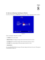
1) Press on the M button to change the month to be searched, D for day, h for hour, m for
minute and s for second. The buttons on the left side are to decrease the value, whereas
those on the right side are to increase the value.
2) Move the slide bar between the buttons to change Month, Day, Hour, Minute, and
Second to be searched. Move the slide bar to the left to decrease the value, or to the right to
increase the value.
3) Enter Month, Day, Hour, Minute, and Second directly in display bar.
4) Press OK to select time.
6. Press ARCHIVE button to start archiving. An “.arv” file will be saved.
7. Press STOP button if you wish to cancel archiving.
8. Check “Display video” if you wish to display what you are archiving on the screen while
archiving file at same time.
In order to play the archived EDR MPEG4 Files (.arv), you will need to download viewer:
I. Press Download DVRViewer button.
II. Select “Run” or “Save” the file.
III. Open the DVRViewer.exe for loading the archived EDR MPEG Files (.arv)
Detailed explanation of DVRViewer is as follows:
1.
2.
3.
4.
5.
6.
7.
8.
Load File: load an archived EDR MPEG File (.arv).
Stop: stop playback.
Play: play video.
<<Step: move the paused image one step backward.
Pause: pause playing.
Step>>: move the paused image one step forward.
Capture: save the current image as “.jpg” file.
Save to Avi: save the archived EDR MPEG File as “.AVI” file.
Note:
(1)The recording frame rate will be automatically calculated. It is suggested to use the calculated
Recording Frame Rate, although it is possible to change this value.
(2) If you wish to save the audio recorded, please select Audio ON, so that the audio can be
transferred to AVI file. Otherwise, select Audio OFF.
Note: If you are unable to play “AVI” file downloaded from “DVRViewer”, your PC may require
a video codec.
The codec can be found at the following URL: http://www.divx.com/divx/windows/codec/
If you continue to have problems or are unable to download this file, you can also try
http://www.cole2k.net/?display=Codec-Pack-Advanced
14.4 Remote Configuration
Click on the “CONFIG” tab to open a page where you can remotely change the DVR’s settings.
Click on each option to go to the settings for that page.
When you finish making changes on a screen, press Apply to save the settings.
Press Reset to display the DVR’s current menu settings.
The settings you make remotely in this page are virtually the same as the way you set up the DVR
itself, except for as noted in the following pages.
DATE/TIME setup menu
Set Date/Time Manually
1. Click on the calendar button to set Date/Time manually. A calendar will show up as
shown below.
2. Click “<<” to decrease Year value, “>>” to increase Year value.
3. Click “<” to decrease Month value, “>” to increase Month value.
4. Click on the selected date directly.
5. Click on the Hour, Minute, Seconds to change Time value. Up arrow for increasing and
Down arrow for decreasing the value. This is also used to change between Am and Pm.
6. Finally, click Apply to confirm setting.
CAMERA setup menu
RECORD setup menu
ALARM setup menu
MOTION setup menu
Set Motion Grid
1. Non-green squares are disabled for motion; green squares are enabled.
2. Click and hold the mouse to begin selecting squares in the motion grid.
3. Drag the mouse to highlight the desired area.
4. The selected area will switch to the opposite color.
5. Click Apply to save the changes.
VIDEO LOSS setup menu
NETWORK 1 setup menu
The Network Configuration Settings can not be changed remotely. These must be changed
in the DVR’s Network Menu.
NETWORK 2 setup menu
After saving changes to the account, password, or level, the changes will take effect the
next time you log in to the network viewer.
SCHEDULE setup menu
CONTROL setup menu
WARNING setup menu
SYSTEM setup menu
All recording should be stopped before making any changes on this menu.
Update Firmware
1. After clicking Apply, an “Open File” window appears.
2. Find the folder where the firmware upgrade is saved and choose Open.
3. On the DVR’s monitor, you will see a notice that the firmware is being updated.
Note: DO NOT try to open the menu or make changes at the DVR while this
process is happening.
4. When the update is complete, the DVR will reboot automatically.
5. Once “Load System” has finished, the system’s software will be updated. You will need
to refresh the network viewer for the changes to take effect.
Load/Save Configuration
1. Clicking Save will open a “Save File window.
2. Select the folder you wish to save the configuration file to and then choose Save.
3. Clicking Load will open an “Open File” window.
4. Find the folder where your configuration file is saved and then choose Open.
Chapter
15
15. Interface Specifications
RS485
This Digital Video Recorder may be controlled by a computer or control keyboard (EKB500)
via the RS485 interface. Pin definition of RS-485 connector on DVR back panel is shown in
the following picture.
1 2 3
4
5
6
7
8
Pin 3: RS-485 +
Pin 6: RS-485 -
15.1 Transmission Setting
There are 6 different speeds that can be used to transmit instruction or information through the
RS485 port on the device, 1200 baud, 2400 baud, 4800 baud, 9600 baud, 19200 baud, and
38400 baud. The default setting from the factory is 9600 baud.
15.2 Remote Control Protocol
A computer can be used to control the DVR by sending the packet as follows.
=========================================================
485/232 Control Code Protocol
=========================================================
1-1. Sample control code packets
Example1: A packet that send "REC" key to EDR(ID=5)
0x85 (length)
0x00 (Receiver ID high byte)
0x05 (Receiver ID low byte)
0x4B (OPcode = key)
0x08 (DATA1 = "Rec" keycode)
0x5D (checksum)
Example2: A packet that send "PAUSE" key to EDR(ID=4999)
0x85 (length)
0x27 (Receiver ID high byte)
0x07 (Receiver ID low byte)
0x4B (OPcode = key )
0x0C (DATA1 = "Pause" keycode )
0x0A (checksum)
Example3: A packet that send "PLAY" key to all EDR(broadcast)
0x85
0x7f
0x7f
0x4B
0x0B
0x59
(length)
(Receiver ID high byte)
(Receiver ID low byte)
(OPcode = key )
(DATA1 = "Play" keycode )
(checksum)
2-1. The format of message packet is as follows:
Length Byte (Prefix: 0x86, 0x87, or 0x88 ..... )
Receiver ID high byte
Receiver ID low byte
Opcode Byte
Data Byte1
Data Byte2
Data Byte3
.
.
Checksum Byte
2-2. Length Byte
This Length Byte is also a prefix. Bit7 must be 1.
EX: 0x87 ==> this packet has 7 bytes length. (not included Length byte itself)
2-3. Receiver ID
1). Individual receiver ID
---------------------------------------------------------Decimal 14bit binary value Hbyte Lbyte Receiver ID
------- ------------------- ------ ----- ----------0
0000000 0000000
00 00 ID = 0
1
0000000 0000001
00 01 ID = 1
2
0000000 0000010
00 02 ID = 2
....
126 0000000 1111110
00 7e ID = 126
127 0000000 1111111
00 7f ID = 127
128 0000001 0000000
01 00 ID = 128
129 0000001 0000001
01 01 ID = 129
255 0000001 1111111
01 7f ID = 255
256 0000010 0000000
02 00 ID = 256
....
511 0000011 1111111
03 7f ID = 511
....
16382 1111111 1111110
7f 7e ID = 16382
---------------------------------------------------------2). Broadcast ID
---------------------------------------------------------Decimal 14bit binary value Hbyte Lbyte Receiver ID
------- ------------------- ------ ----- ----------16383 1111111 1111111
7f 7f All EDR connect to RS485/RS232
---------------------------------------------------------2-4. Opcode Byte & Data bytes
2-4-1. OPcode
-----------------------------------------OPcode Data1 Function
------ ------ -------------------------0x4B Keycode A remote key pressed
-----------------------------------------2-4-1. A remote key pressed (OPcode=0x4B)
------------------------------Data1 Key for EDR810/EDR410
------ ----------------------0x00 CH1
0x01 CH2
0x02 CH3
0x03 CH4
0x04 MODE
0x05 ZOOM
0x06 SEQ
0x07 MENU
0x08 REC
0x09 REV.PLAY
0x0A STOP
0x0B PLAY
0x0C PAUSE
0x0D SEARCH
0x0E COPY
0x0F DISPLAY
0x10 SHUTTLE<<0
0x11 SHUTTLE<<1
0x12 SHUTTLE<<2
0x13 SHUTTLE<<3
0x14 SHUTTLE<<4
0x15 SHUTTLE<<5
0x16 SHUTTLE<<6
0x17 SHUTTLE>>0
0x18 SHUTTLE>>1
0x19 SHUTTLE>>2
0x1a SHUTTLE>>3
0x1b SHUTTLE>>4
0x1c SHUTTLE>>5
0x1d SHUTTLE>>6
0x1e JOG<
0x1f JOG>
0x20 CH5
0x21 CH6
0x22 CH7
0x23 CH8
0x24 (reserve)
0x25 (reserve)
0x26 (reserve)
0x27 (reserve)
0x28 (reserve)
0x29 (reserve)
0x2a (reserve)
0x2b (reserve)
0x2c SELECT
0x2d CALL
0x2e ENTER
0x2f (reserve)
0x30 (reserve)
0x31 (reserve)
0x32 (reserve)
0x33 (reserve)
0x34 (reserve)
-------------------------------
2-5. Checksum Byte
Checksum is computed as the sum of all previous bytes (including the length byte), then mask with
0x7f.
Appendix
A
Appendix A: Remote Control
Appendix
B
Appendix B: Alarm Board Configuration
Alarm I/O pin assignment
The alarm connector, Figure 1, is used to provide one sensor alarm input for each camera input.
For easy operation, an alarm extension board, Figure 2, is provided to connect to the alarm
connector.
Each alarm input requires two wires, one wire connects to the desired alarm input pin, the second
wire connects to the ground. The alarm signal assignment is shown as below.
<Figure 1>
D-SUB 25 pin female connector
(DVR)
<Figure 2>
PR16D00400 Alarm extension
board (HOST)
PIN #
1
2
3
4
5
6
7
8
9
10
11
12
13
14
15
16
17
18
19
20
21
22
23
24
25
DVR
NAME
GND
ALM 1
ALM 2
ALM 3
ALM 4
ALM 5
ALM 6
ALM 7
ALM 8
--------------------------------ALMRSTO
REC
REC-IN
DISKFULL
----ALM-N.C
ALM-N.O
ALM-COM
PIN #
1
2
3
4
5
6
7
8
9
10
11
12
13
14
15
16
17
18
19
20
21
22
23
24
25
26
27
28
HOST
NAME
GND
ALM 1
ALM 2
ALM 3
ALM 4
ALM 5
ALM 6
GDN
ALM 7
ALM 8
--------------------------------ALMRST
REC-IN
GND
----DISKFULL
----ALM-N.C
ALM-N.O
ALM-COM
GND
Troubleshooting
If you have difficulty operating your system, run through the following checklist to see if
you can solve the problem.

The DVR will not go into record mode?
Make sure the HDD is locked in with the key. Also check to make sure the hard drive is
set to Master. A diagram located on the Hard Drive Label will show you how to set the
drive to master.

The DVR displays no picture?
First you should check if the equipment is connected properly. See Chapter 1 for help.
The second thing to check is if all the wires work properly.
The next step is to verify the recorder and cameras are getting the correct amount of
power.

There is no display coming from one of the channels on the DVR?
The first step is to verify is the problem coming from the recorder or the camera.
Simply take a working camera and plug it into the port that seems to not be working. If
you see a picture this means the problem is coming from the camera.

I cannot connect to the recorder via the internet?
1.
Are you using Internet Explorer?
2.
Make sure you have downloaded and installed the ActiveX controls. For help
with this, see Chapter 14.
3.
Are you using the IP address from the Internet Service provider?
4.
Does your internet provider block any ports?
5.
If you are using a router are the ports in your router opened?
(NOTE: Please refer to “Network Setup Menu” section for port settings. For
example, HTTP port: 00080, Control port: 01600, Data port: 37260)
EverFocus Electronics Corp.
Head Office:
12F, No.79 Sec. 1 Shin-Tai Wu Road,
Hsi-Chih, Taipei, Taiwan
TEL: +886-2-26982334
FAX: +886-2-26982380
www.everfocus.com.tw
Europe Office:
Albert-Einstein-Strasse 1
D-46446 Emmerich, Germany
TEL: 49-2822-9394-0
www.everfocus.de
USA Office:
1801 Highland Ave. Unit A
Duarte, CA 91010, U.S.A.
TEL: +1-626-844-8888
FAX: +1-626-844-8838
www.everfocus.com
China Office:
Room B-05D-1, KESHI PLAZA , Shangdi
Information Industry Base, Haidian District,
Beijing China 100085
TEL: +86-10-62973336/37/38/39
FAX: +86-10-62971423
www.everfocus.com.cn
USA N.Y. Office:
415 Oser Avenue Unit S
Hauppauge, NY 11788
TEL: 631-436-5070
FAX: 631-436-5027
www.everfocus.com
Your EverFocus product is designed
and manufactured with high quality
materials and components which can
be recycled and reused.
This symbol means that electrical and
electronic equipment, at their
end-of-life, should be disposed of
separately from your household waste.
Please, dispose of this equipment at
your local community waste
collection/recycling centre.
In the European Union there are
separate collection systems for used
electrical and electronic product.
Please, help us to conserve the
environment we live in!
Japan Office:
1809 WBG MARIBU East 18F,
2-6 Nakase.Mihama-ku.
Chiba city 261-7118, Japan
TEL : +81-43-212-8188
FAX : +81-43-297-0081
www.everfocus.com
Ihr EverFocus Produkt wurde entwickelt
und hergestellt mit qualitativ
hochwertigen Materialien und
Komponenten, die recycelt und wieder
verwendet werden können.
Dieses Symbol bedeutet, dass
elektrische und elektronische Geräte am
Ende ihrer Nutzungsdauer vom
Hausmüll getrennt entsorgt werden
sollen.
Bitte entsorgen Sie dieses Gerät bei
Ihrer örtlichen kommunalen
Sammelstelle oder im Recycling Centre.
Helfen Sie uns bitte, die Umwelt zu
erhalten, in der wir leben!
P/N: M41HG0010E _Ver. H