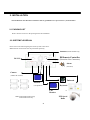
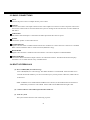
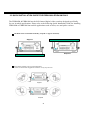
1
INSTRUCTION MANUAL
Digital Eight Channels/Four Channels Video Recorder
EDR810H/810M/
410H/410M
V 1.21
About this manual
Before installing and using this unit, please read this Manual carefully.
Be sure to keep it handy for later reference.
Updated on: Nov. 17th 2005
Federal Communication Commission Interference Statement
This equipment has been tested and found to comply with the limits for a Class B digital device,
pursuant to Part 15 of the FCC Rules. These limits are designed to provide reasonable protection
against harmful interference in a residential installation. This equipment generates, uses and can
radiate radio frequency energy and, if not installed and used in accordance with the instructions,
may cause harmful interference to radio communications. However, there is no guarantee that
interference will not occur in a particular installation. If this equipment does cause harmful
interference to radio or television reception, which can be determined by turning the equipment
off and on, the user is encouraged to try to correct the interference by one of the following
measures :
• Reorient or relocate the receiving antenna.
• Increase the separation between the equipment and receiver.
• Connect the equipment into an outlet on a circuit different from that to which the receiver is
connected.
• Consult the dealer or an experienced radio/TV technician for help.
FCC Caution : Any changes or modifications not expressly approved by the party responsible
for compliance could void the users’s authority to operate this equipment.
This device complies with Part 15 of the FCC Rules. Operation is subject to the following two
conditions : (1) This device may not cause harmful interference, and (2) this device must accept
any interference received, including interference that may cause undesired operation.
This device and its antennas(s) must not be co- located or operating in conjunction with any
other antenna or transmitter.
This advice complies with Part 15 of the FCC Rules. Operation is subject to the
following two conditions: (1) this device may not cause harmful interference, and (2)
this device must accept any interference received, including interference that may cause
undesired operation.
Safety Warning
WARNING
TO REDUCE RISK OF FIRE OR ELECTRIC SHOCK,
DO NOT EXPOSE THIS APPLIANCE TO RAIN OR MOISTURE .
CAUTION
DO NOT REMOVE COVER. NO USER SERVICEABLE PARTS INSIDE.
REFER SERVICING TO QUALIFIED SERVICE PERSONNEL.
Note:
This equipment has been tested and found to comply with the limits for a Class A digital device,
The changes or modifications not expressly approved by the party responsible for compliance
could void the user's authority to operate the equipment.
Note:
This is a class A product. In a domestic environment this product may cause radio interference
In which case the user may be required to take adequate measures.
Notice:
The information in this manual was current when published. The manufacturer
reserves the right to revise and improve its products. All specifications are
therefore subject to change without notice.
2
Safety Precautions
Safety Precautions
?Refer all work related to the installation of this product to qualified service
personnel or system installers.
?Do not block the ventilation opening or slots on the cover.
? Do not drop metallic parts through slots.This could permanently damage
the appliance. Turn the power off immediately and contact qualified service
personnel for service.
?Do not attempt to disassemble the appliance.To prevent electric shock,
do not remove screws or covers. There are no user-serviceable parts
inside. Contact qualified service personnel for maintenance. Handle the
appliance with care. Do not strike or shake, as this may damage the
appliance.
?Do not expose the appliance to water or moisture, nor try to operate it in
wet areas. Do take immediate action if the appliance becomes wet.
Turn the power off and refer servicing to qualified service personnel.
Moisture may damage the appliance and also cause electric shock.
?Do not use strong or abrasive detergents when cleaning the appliance
body. Use a dry cloth to clean the appliance when it is dirty. When the
dirt is hard to remove, use a mild detergent and wipe gently.
?Do not overload outlets and extension cords as this may result in a risk of
fire or electric shock.
?Do not operate the appliance beyond its specified temperature, humidity
or power source ratings. Do not use the appliance in an extreme
environment where high temperature or high humidity exists. Use the
appliance at temperature within indoor type DVR for 0o C ~ +40o C and a
humidity below 90%.
The input power source for this appliance is AC100~240V.
3
Safety Precautions
Safety Precautions
The lightning flash with an arrowhead symbol, within an
equilateral triangle, is intended to alert the user to the presence
of uninsulated ” dangerous voltage ” within the product’s enclosure
that may be of sufficient magnitude to constitute a risk of electric
shock to persons.
Warning:
Electrostatic-sensitive device. Use proper
CMOS/MOSFET handing precautions to avoid
electrostatic discharge.
Do not place on uneven or unstable work surfaces.
Seek servicing if the casing.
The exclamation point within an equilateral triangle is
intended to alert the user to presence of important operating
and maintenance(servicing)instructions in the literature
accompanying the appliance.
Warning :
To prevent fire or shock hazard, do not expose units not
specifically designed for outdoor use to rain or moisture.
Attention:
Installation should be performed by qualified service personnel only
in accordance with the National Electrical Code or applicable local codes.
Power Disconnect:
Units with or without ON-OFF switches have power supplied to the unit
whenever the power code is inserted into the power source; however, the
unit is operational only when the ON-OFF switch is in the ON position.
The power cord is the main power disconnect for all units.
External Power Supplies
Use only the recommended power supplies.
Power supplies must comply with the requirement of
the latest version of IEC 60065/CNS 13439. Substitutions
may damage the unit or cause a fire or shock hazard.
AC100~240V Power Cords
AC100~240V power cords
4
Important Safeguards
Important Safeguards
Read Instruction---All the safety and operating instructions should be read before the unit is operated.
Retain Instructions---The safety and operating instructions should be retained for future reference.
Heed Warnings— All warnings on the unit and in the operating instructions should be adhered to.
Follow Instructions— All operating and use instructions should be followed.
Cleaning— Unplug the unit from the outlet before cleaning. Do not use liquid cleaners or aerosol cleaners.
Use a damp cloth for cleaning
Attachments— Do not use attachment not recommended by the product manufacturer as they may cause hazards.
Water and Moisture— Do not use this unit near water-for example, near a bath tub, wash bowl, kitchen sink,
or laundry tub, in a wet basement, near a swimming pool, in an unprotected outdoor installation, or any area which is
classified as a wet location.
Servicing— Do not attempt to service this unit by yourself as opening or removing covers may expose you to dangerous
voltage or other hazards. Refer all servicing to qualified service personnel.
Power Cord Protection— Power supply cords should be routed so that they are not likely to be walked on or pinched by
items placed upon or against them, playing particular attention to cords and plugs, convenience receptacles, and the point
where they exit from the appliance.
Object and Liquid Entry— Never push objects of any kind into this unit through openings as they may touch dangerous
voltage points or short-out parts that could result in a fire or electric shock. Never spill liquid of any kind on the unit.
5
Table of Contents
1. PRODUCT INTRODUCTION … … … … … … … … … … … … … … … … … … … … … … … .… … … …
8
1.1 FEATURES … … … … … … … … … … … … … … … … … … … … … … … … … ..… … … … ..… … … … .
8
1.2 SPECIFICATIONS… … … … … … … … … … … … … … … … … … … … … … … … … … … … … .… … …
9
1.3 FRONT PANEL KEYPADS … … … … … … … … … … … … … … … … … … … … … … ..… … .… … …
11
1.4 BACK PANEL CONNECTORS … … … … … … … … … … … … … … … … … … … … … … … .… … …
14
1.5 MONITOR DISPLAY … … … … … … … … … … … … … … … … … … … … … … … … … … … .… … …
17
2. INSTALLATION … … … … … … … … … … … … … … … … … … … … … … … … … … … … … .… … … …
20
2.1 PACKING LIST … … … … … … … … … … … … … … … … … … … … … … … … … … … ...… … .… … …
20
2.2 SYSTEM FLOORPLAN … … … … … … … … … … … … … … … … … … … … … ..… … … … … .… … …
20
2.3 BASIC CONNECTIONS … … … … … … … … … … … … … … … ..… … … … … … … … .… … .… … …
21
2.4 BOOT UP EDR810/410… … … … … … … … … … … … … … … … … … … … ..… … … … … … .… … …
21
2.5 QUICK INSTALLATION GUIDE FOR EDR810M & EDR410M ONLY… … … .… … … … … … …
22
3. MENU SETUP… … … … … … … … … … … … … … … … … … … … … … … … … … … … … … … … … …
28
3.1 TIME/DATE SETUP MENU … … … … … … … … … … … … … … .… … … … … … … … … … … … .…
28
3.2 CAMERA SETUP MENU … … … … … … … … … … … … … … … … … … … … … … … … … … … .… .
32
3.3 RECORD SETUP MENU … … … … … … … … … … … … … … … ..… … … … … … … … … … … .… …
35
3.4 ALARM SETUP MENU … … … … … … … … … … … … … … … … … … … … … … … … … … … .… …
37
3.5 MOTION SETUP MENU … … … … … … … … … … … … … … … ..… … … … … … … … … … … … … …
39
3.6 VLOSS SETUP MENU … … … … … … … … … … … … … … … … .… … … … … … … … … … … .… …
42
3.7 NETWORK SETUP MENU … … … … … … … … … … … … … … ..… … … … … … … … … … … .… …
44
3.8 SCHEDULE SETUP MENU … … … … … … … … … … … … … … … … … … … … … … … … … … … …
49
3.9 DISK SETUP MENU … … … … … … … … … … … … … … … … … … … … … … … … … … … .… … …
50
3.10 CONTROL SETUP MENU … … … … … … … … … … … … … … … … … … … … … … … … … … … .
51
3.11 WARNING SETUP MENU… … … … … … … … … … … … … … … … … … … … … … … … … … … …
52
3.12 SYSTEM SETUP MENU … … … … … … … … … … … … … … … … … … … … … … … … … … .… …
56
4. RECORDING … … … … … … … … … … … … … … … … … … … … … … … … … … … … … … … … … …
59
4.1 INSTANT RECORDING … … … … … … … … … … … … … … … … … … … … … … … … … … … ..… …
59
4.2 SCHEDULE RECORDING … … … … … … … … … … … … … … … … … … … … … … … … … … … …
60
4.3 EVENT RECORDING … … … … … … … … … … … … … … … … … … … … … … .… … … … … … .… …
60
4.4 ALARM INPUT RECORDING … … … … … … … … … … … … … … … … … ..… … … … … … … … …
61
6
Table of Contents
5. PLAYING BACK… … … … … … … … … … … ..… … … … … … … … … … … … … … … … … ..… … … ...
62
5.1 NORMAL PLAYBACK… … … … … … .… … … … … … … … … … … … … … … … … … … … … … … …
62
5.2 SEARCH PLAYBACK … … … … … … … … … … … … … … … … … … … … .… … … … … … … … … …
64
6. COPY TO A VIDEO FILE … … … … … … … … … … … … … … … … … … … .… … … … … … … … … …
66
7. CALL … … … … … … … … … … … … … … … … … … … … … … … … … … … ..… … … .… … … … … … …
68
8. SCREEN DISPLAY SETTING … … … … … … … … … … ..… … … … … … ..… … … … … … … … … …
70
9. SCREEN DISPLAY MODE … … … … … … … … … … … … … .… … … … … .… … … … … … … … … …
71
10. REMOTE VIEWER … … … … … … … … … … … … … … ..… … … … … … ..… … … … … … … … … …
72
APPENDIX A: RS232 specifications … … … … … … … … … … … … … … … … … .… … … … … … … …
78
APPENDIX B: RS485 specifications … … … … … … … … … … … … … … … … … … .… … … … … … …
79
APPENDIX C: Alarm I/O Assignment … … … … … … … … … … … … … … … … .… … … … … .… … …
80
APPENDIX D: Troubleshooting … … … … … … … … … … … … … … … .… … … .… … … … … .… … …
81
7
1. PRODUCT INTRODUCTION
The Digital Video Recorder is the industry’s first full-featured digital video recorder
designed specifically for use in security industry. The Digital Video Recorder
incorporates all the benefits of digital video recording, is simple to install, and operates
just like a VCR. Highly efficient compression technology and superior resolution of
recorded images make the Digital Video Recorder stand out from the competition as the
best choice for security surveillance.
1.1 FEATURES
?
?
?
?
?
?
?
?
?
?
?
?
?
?
Duplex Operation for Recording & Playback
Built-in MPEG4 Codec with Configurable Quality
Variable Recording Speeds up to 60/50 Images per second for NTSC/PAL
Audio Recording Capabilities
Motion Detection Capabilities
One 3.5” Hard Disk with Hot-Swap Tray for Internal Storage
Ethernet Interface for Remote Network Viewing
Optional Wireless LAN Interface for Data Transmission (Reserved)
RS232 and RS485 for Remote Control
Shuttle/Jog Dial for Picture-by-Picture or Fast/Slow Viewing
Easy-to-use Control Panel with Common VCR and Multiplexer Functions
On-Screen Menus Operations with Multi-Language Support
Real-Time Live Display for all Cameras
Easy archiving of video and Remote Viewer through USB port
8
1.2 SPECIFICATIONS
Video Format
NTSC/EIA or PAL/CCIR
Video Input
4/8 camera inputs (BNC), 1Vp-p/75ohm
1 BNC video out (1Vp-p/75ohm) for Main Monitor
Video Output
Video Compression
Recording Resolution
1 BNC video out (1Vp-p/75ohm) for CALL Monitor
4 video out (1Vp-p/75ohm) for Looping (4 Channels
only)
MPEG4
720x240, 720x480 or 360x240 for NTSC
720x288, 720x576 or 360x288 for PAL
Video Display
Full, PIP, 4, 7, 8/9 and 2x2 Zoom for Live Viewing
and Playback
Display Resolution
720x240, 720x480 or 360x240 for NTSC
720x288, 720x576 or 360x288 for PAL
Video Pause
Yes
4/8 Alarm Inputs
4/8 Alarm Inputs
1 Alarm Output
1 Alarm Output
Hard Disk Storage
One Hot-Swappable 3.5” IDE Hard Disk
Recording Rate
Up to 60/50 Images per second for NTSC/PAL
Recording Mode
Continue, Time-lapse, Schedule,
Event recording (Motion and Alarm)
Playback Rate
Up to 60/50 Images per second for NTSC/PAL
Playback Search
By Date/Time or Event (Motion, Video Loss, Alarm)
Motion Detection
Yes, with MULTIPLE configurable detection areas &
sensitivity
Video Loss Detection
Yes
Event Log
Yes
User Interface
User-friendly Menu Driven
Setup
On screen display setup
User Input Device
Timer
Front panel keypad with Shuttle/Jog, Keyboard
(optional)
Built-in real time clock and Auto Time
Synchronization with global NTP server through
Internet
Watch Dog Timer
Yes
9
Title
12-characters title for each camera
Ethernet
RJ45 connectors for network communication
Archive
USB for archiving
Archive through Wireless transmission (Reserved)
RS-232
9-pin female connector for local communication
RS-485
for Keyboard connection
Audio
2 mono inputs, 2 mono (SPEAKER) outputs
Power Rate
DC 12V/DC 24V
Dimension
Weight
Operating
Temperature
Remote Controller
Half size: 320 mm (L) x 215mm (W) x 100mm (H)
Mobile : 320.8mm (L) x 215mm (W) x 109.9mm(H)
4.85 KG
0oC ~ +50oC
IR Remote Controller
IR Remote Controller with Extension Wire(optional)
10
1.3 FRONT PANEL KEYPADS
KEY
1
~
8
Channel Key: Press FULL+Channel Key (CH1~CH8 ) to display video image in the full screen
format the picture of the corresponding will fill the whole screen of the monitor display.
1
CH1 / REC: Press this key to start instant recording.
2
CH2 / REV. PLAY: Reverse Play Back.
3
CH3 / STOP: Press this key to stop recording and playing back.
4
CH4 / PLAY: Play Back.
5
CH5 / PAUSE: Press this key to pause the playback picture.
6
CH6 / SEARCH: Press this key to enter the SEARCH MENU.
7
CH 7 / COPY: Press this key to start to copy video stream under PAUSE mode into USB.
8
CH8 / ENTER: Press this key to enter items , or jump to next subentry in the menu setting.
9
FULL: Press this key and channel Key at the same time to switch to full screen in both live mode and
play back mode. Press “MODE” to exit full screen.
11
10 MODE: Switch PIP, 4, 7, and 8 displays in Live and Playback modes.
11 ZOOM: Press this key while viewing the full screen image to display a magnified resolution on the
monitor. You must be in “Full” screen mode first before zooming. While zooming, all other
function keys will be disable until you press “ZOOM” again to exit “ZOOM” mode.
12
SEQ : Press this key to enter the auto sequential switching mode.
13 SELECT: Press this key to select, to assign a camera to a display, to adjust screen display, and so on.
14 CALL: Press this key to enter and set up CALL MENU.
15
DISPLAY: Press this key to switch display of channels and/or status bar.
16
MENU: Press this key to enter or quit MAIN SETUP MENU.
17
HDD LOCK: Protect HDD without steal and turn on HDD power.
18
Hard Disk Tray: Hard Disk holder for HDD.
12
19
Shuttle and Jog Dial
Shuttle: In the Playback mode, turn the Shuttle dial to fast forward/rewind
the video.
In the Pause mode, turn the Shuttle dial to slow forward/rewind
the video.
In the Search mode, turn the Shuttle to change pages.
Jog Dial: In the Pause mode, turn the Jog dial to forward/rewind the video.
In the Menu mode, turn the Jog dial to change settings and values
in subentries.
20
USB Slot: Insert a USB to archive an image or video file.
21
HDD LEDs: LEDs for HDD active power (GREEN) and data reading /writing (YELLOW).
22
Remote Control: IR remote control receiver.
23
System LEDs: LEDs for system active LAN, ALARM and POWER display.
13
1.4 BACK PANEL CONNECTORS
Back panel of 810M
Back panel of 810H
Back panel of 410M
Back panel of 410H
POWER
1
Main Power plug: Connect the DC 12~ 24V power source to adapter for AC 100~ 240V.
14
AUDIO
2
Audio IN: Audio input for recording, and it can be set to “YES” or “NO” in the RECORD SETUP
MENU.
Audio OUT: Connect to an audio input of a monitor or other device.
MONITOR
3
MAIN MONITOR: This connector is used for the main monitor display, a number of different
display modes may be selected for viewing.
4
CALL MONITOR: This connector is used for the call monitor. This monitor can only display a full
screen or a quad screen.
VIDEO IN
5
For EDR810 Series:
VIDEO IN(1~8): The BNC connectors of video input enables the system to receive the
signals from each camera through the 75 ohm coaxial cables.
Alarm Input/Output
6
Alarm Input
ALM-INPUT:
Normal open or normal close type alarm signal inputs.
The Alarm Input can be selected as Normal Open (N.O.), Normal
Close (N.C.), N.C. TRANS., or N.O, TRANS input in the ALARM SETUP MENU.
When an alarm occurs, alarm recording will automatically start.
ALM-OUTPUT: A build-in relay offers 3 nodes which are ALM-COM (common), ALM-NO
(normal open) and ALM-NC (normal close) for external use.
Note: Please check APPENDIX C to see other available alarm input/output functions.
15
LAN
7
LAN Connector: The RJ-45 LAN connector.
RS232
8
RS232 connector: Connect D-Sub 9 pins connector to RS232 ports for remote control.
RS485
9
RS485 connector: RJ 45 Connector to Cascade multi Digital Video Recorder.
Remote
10
Remote Control: Remote control port provides you an extension wire with an IR receiver instead of
the IR receiver on the front panel.
Note: The IR receiver extension line (10m) must be purchased separately.
Wireless LAN
11
(Reserved)
Antenna: Integrated IEEE 802.11b/g wireless LAN capabilities. The antenna port is for wireless
network antenna use (For EDR810M option).
12
FAN: Cooling FAN.
16
1.5 MONITOR DISPLAY
The status information of the cameras or machine will show up, and be located at different places on the
screen.
1. Channel tag
2. Event sign
3. Select sign
2. Event sign
4. Play status bar
5. Record status bar
1
Channel tag: A channel tag indicates the channel name of the screen.
2
Event sign: Event signals which are small icons with a capital letter and red background show the
events on each screen. There are 4 different signals which are
A : Alarm event. The alarm place where the camera locates. In order to show the
camera video to a corresponding alarm, setting a FOCUS CAMERA in ALARM
SETUP MENU is necessary.
M : Motion event. Motion event only shows up when the camera ’s MOTION is enabled
in MOTION SETUP MENU, and the camera detects a motion.
V : Video loss event. Video loss event only shows when the camera ’s VLOSS is
enabled in VLOSS SETUP MENU, and the camera signal is lost.
S : Sequence sign. Sequence sign shows up when the display is in the sequence mode.
The sequence display is located on display with a “*” sign in 4, 7, Full screen and PIP
(picture in picture) display mode. The
display when sequence occurs.
17
S sign will replace “*” sign in the
3
Select sign: You can assign a camera to a display by pressing SELECT key in life mode. Dial Jog to
move the select sign to the display you would like to change camera, and then press FULL +
channel key to relocate the camera.
4
Play status bar: The play status bar appears in play back mode if you enable a status bar on the screen
(Check page 12, item 15th, DISPLAY). Three parts which are play date, play time and
play status are shown in the play status bar.
Play Date
Play Status
Play Time
1. Play date: The play date in which the video is recorded.
2. Play status: It shows PAUSE, play speed and reverse play speed.
“PAUSE”, when the video play is paused.
“>” means normal play speed;
“<“ means normal reverse play speed;
“>> x N” means N time fast play speed;
“<< x N” means N time fast reverse play speed.
3. Play time: The play time at which the video is recorded. The time format depends on
the time format setting in the TIME/DATE SETUP MENU.
5
Record status bar: The record status bar appears when you enable a status bar on the screen (Check
page 12, item 15th, DISPLAY). Three parts which are current date, record status (% of space used for
recording) and current time.
Current Date
Record Status
Event
HDD/FAN Status
18
Current Time
1. Current date: The current date which is set in the TIME/DATE SETUP MENU.
2. Record status: It shows REC and recording hard disk number.
“REC”, it shows when machine is recording.
“R01”, the recording hard disk number. There is only one hard disk available in
this model, so it always shows R01 when recording.
3. Event: The last happened event.
4. Current time: The current time which is set in the TIME/DATE SETUP MENU.
5. HDD/Fan status: “No Disk”, it shows when no disk is installed or detected.
“No Fan”, it shows when cooling fan stops working.
19
2. INSTALLATION
The installations described below should be done by qualified service personnel or system installers.
2.1 PACKING LIST
Please check accessories in the packing before the installation.
2.2 SYSTEM FLOORPLAN
Please refer to the following diagram for the system connections.
Note: Monitor and Camera must be purchased separately.
Antenna (Mobile Model only)
IR Remote Controller
RS 232
(Extension Line Connector)
Alarm
(In & Out)
Camera
(VIDEO & AUDIO)
Internet
Monitor
(and Speaker)
Keyboard
Call
Monitor
or
PTZ Speed
Dome
Note: 810H/810M without relay
410H/410M with relay
20
2.3 BASIC CONNECTIONS
Power
Connect the power source or adapter into the power socket.
Cameras
Connect each camera video input connector to the video output from a camera or other composite video source.
At least one camera must be connected before the system is running for the auto detection of video standard to
take effect.
Audio In/Out
The camera audio In/Output is connected to the audio input terminal at the rear panel.
Speaker
Connect the speaker or other audio devices.
10/100M Ethernet
Digital Video Recorder is enabled control from the PC via Ethernet. Connect the LAN connector to a standard
RJ45 connector Ethernet cable or wireless network (IEEE 802.11b/g).
RS232/RS485
Digital Video Recorder is enabled control from the PC or EverFocus keyboard via RS232/RS485.
Main/Call Monitor
Connect the Main/Call monitor output connector to a Main/Call monitor. The Main/Call monitor displays
selected live or recorded cameras in any available format.
2.4 BOOT UP EDR810/410
(1) Insert a HDD (IDE) for Video Storage
Insert a HDD(IDE) for Video Storage. The HDD should be set as MASTER. After hard disk case is
inserted into the hard disk tray, be sure to turn the tray key in lock position. Otherwise, HDD will not
be detected.
Note: A HDD has to be installed before EDR810/410 is booted, or the EDR810/410 will not detect a
HDD until you reboot it with a HDD. Please make sure the HDD indicator light is ON.
(2) Connect cable for video/audio input and video/audio out.
(3) Turn on system
The system will be turned on after connecting to power.
21
2.5 QUICK INSTALLATION GUIDE FOR EDR810M & EDR410M ONLY
The EDR810M & EDR410M are the full- featured digital video recorders designed specifically
for use in mobile applications. Please refer to the following Quick Installation Guide for installing
EDR810M or EDR410M into mobile applications such as buses, cars and police cruisers.
The DVR can be mounted horizontally (suspend or support mounted).
Interface
Support
EDR410M
EDR410M
Suspend
Interface
Show all the possible ways to mount the DVR.
Use the two Z-brackets supplied to mount it in any ways shown.
EDSR400M
Support
EDSR400M
Suspend
22
Quick Install Guide :
1. Unpack Everything
Make sure you have everything you need before you begin the installation.
2. Equipment Required
The following tools may help you to complete the installation:
•Drill
•Screwdrivers
•Wire cutters
3. Choosing the Location
Choose a location for installation that:
•Provides convenient access for installing or removing the hard drive
•Allows air to flow around the fan vents. Inadequate or improper air flow can impede proper operation of the unit
Avoid any location for installation:
•That is subject to high vibration
•That is subject to high sunlight levels
•That is subject to drenched of the rain
•Where passengers can interfere with unit
•Next to a heater duct
The following table lists the recommended location options.
Location
Convenient operation
Easy to install
Low vibration
Good air flow
Bottom of glove box- horizontal mount
Yes
Yes
Yes
Yes
Bottom of passenger seat next to the driver
NO
Yes
Yes
Yes
Underneath bulkhead-horizontal mount
Yes
Yes
NO
Yes
Front of bulkhead-horizontal mount
Yes
Yes
Yes
Yes
Beside deriver seat-horizontal mount
Yes
Yes
Yes
Yes
Caution: Do not install the DVR on the floor or on the transmission access hatch. These locations have the highest levels of vibration and may
be subject to water damage.
23
Possible Installation Locations Inside the Automobile Vehicle: Truck
Glove box (inside or underneath)
Drive seat ( between seat and wall) or Passenger seat (underneath)
( Users are suggested to use “support” for mounting option)
Show the wiring on the wiring harness that connects to the electrical system.
(24 V)
(5 V)
24
Possible Installation Locations Inside the Automobile Vehicle: TOYOTA CAMRY
Glove box (inside or underneath)
Trunk (Users are suggested to use “suspend”for
mounting option)
Passenger seat (underneath)
Drive seat ( between seat and wall)
Show the wiring on the wiring harness that connects to the electrical system.
25
Installing the Camera(s) and Monitor
The DVR is typically connected to one camera installed inside the car. Other camera(s) can also be installed in different
locations (for example, use the waterproof camera to the outside of vehicle). For installation procedure, refer to the guide
that came with the camera(s) you purchased.
The Monitor power supply connects from the Automotive adapter (c igarette plug)
Monitor and cameras must be purchased separately.
LCD Monitor
LCD Monitor
Connect the Camera(s)
Connect the power connector from the camera(s) harness into the CAMERA POWER OUT jack on the back panel
of the DVR.
Connect the primary camera(s) video connector to the CAMERA INPUT and the audio connector to the AUDIO
INPUT in the back panel.
Adjust the camera(s). After the camera is installed, connect a monitor directly to the camera and observe the image.
Make any adjustment if necessary.
26
Installing the Hard Drive
The following figures are for the 3.5”and 2.5”HDD.
Figure shows 3.5“ HDD
Figure shows 2.5“ HDD
27
3. MENU SETUP
To set up the machine before using is necessary, especially first time to use.
Press the MENU key to enter the MAIN MENU.
Press the MENU key to quit current setting, and go back to last setting.
MENU
Dial the Jog clockwise or counterclockwise to change subentry values.
Press the ENTER key to go next subentry in a menu setting, and press
the DISPLAY key to go last subentry in a menu setting.
3.1 TIME / DATE SETUP MENU
28
In the TIME/DATE SETUP MENU, we define :
(1) TIME FORMAT:
There are two time formats that are 12 HOUR and 24 HOUR to be selected.
(2) TIME: Current time
Hour: 00 ~ 23 (1 ~ 12 if TIME FORMAT is 12 HOUR)
Minute : 00 ~ 59
Second: 00 ~ 59
(3) DATE FORMAT:
There are three date formats which are YYYY-MM-DD, MM-DD-YYYY and DD-MMYYYY to be selected.
(4) DATE: Current date
Date: 01~31
Month:01~12
Year: 2000 ~ 2099
Day:Sun~Mon
(5) DAYLIGHT SAVING:
Select “ON” or “OFF” to enable or disable daylight saving time function.
In order to set a daylight saving time zone, you need to disable daylight saving first. Enable the
daylight saving after finish setting the time zone.
29
(6) START TIME: To set the start time of daylight saving time.
To set the start month of daylight saving time: Dial the jog to set the start month.
JAN
FEB
MAR
APR
MAY
JUN
JUL
AUG
SEP
OCT
NOV
DEC
To set the start week of daylight saving time: Dial the jog to set the start week.
1 ST
2 ND
3 RD
4 TH
LAST
To set the start date of daylight saving time: Dial the jog to set the start date.
SUN
MON
TUE
WED
THU
FRI
SAT
To set the start time of daylight saving time: To set the start “FROM” time and “TO” time of
daylight saving time.
(7) END TIME: To set the end time of daylight saving time.
To set the end month of daylight saving time: Dial the jog to set the end month.
JAN
FEB
MAR
APR
MAY
JUN
JUL
AUG
SEP
OCT
NOV
DEC
To set the end week of daylight saving time: Dial the jog to set the end week.
1 ST
2 ND
3 RD
4 TH
LAST
To set the end date of daylight saving time: Dial the jog to set the end date.
SUN
MON
TUE
WED
THU
FRI
SAT
To set the end time of daylight saving time: To set the end “FROM” time and “TO” time of
daylight saving time.
30
(8) TIME SYNCHRONIZE:
Select “ON” or “OFF” to enable or disable time synchronize which can let you have correct time
automatically when network is connected.
(9) TIME SERVER:
You can set the time server address where you locate if you connect to network and enable time
synchronize. For checking the IP address of NTP Server, please follow the steps:
1. Connect your PC to the internet for searching the IP address of NTP Server.
2. Go to “START” -> “RUN” -> type “Command” and press “OK”
Under Dos Prompt, type “C:\Ping Pool.NTP.ORG to find out the IP address of NTP Server.
(10) TIME ZONE:
You can set the time zone where you locate if you connect to network and enable time
synchronize.
(11) TIME UPDATE BY:
Once you enable the TIME SYNCHRONIZE, you can select the synchronization frequency by:
DAY
WEEK
MONTH
31
3.2 CAMERA SETUP MENU
In the CAMERA SETUP MENU, we define :
(1) TITLE:
The title setting allows you to assign a title to each camera input.
Titling with 12 characters is supported in each channel.
The available alphanumeric characters are:
0,1,2,3,4,5,6,7,8,9,
A,B,C,D,E,F,G,H,I,J,K,L,M,N,O,P,Q,R,S,T,U,V,W,X,Y,Z,
( ) . , + - / and an empty space.
(2) PTZ ID: Select PTZ ID from 001~255 or OFF. The default value is 10+N where N is camera ’s
number. This ID must be the same as the ID used in PTZ Dip Switch.
(3) INSTALL/COVERT: For installation of camera; select “ON” to enable a camera, and “OFF” to
disable it. Please make sure to stop recording before making change of INSTALL. For covert, select
“ON” to cover a camera, and disable the screen in live mode to show up. However, the image is
recorded, and can be played back by user who has playback right. The covert channels will not show
up on the sequence mode.
(4) SEQ(MAIN/CALL): Setup a retention period for sequences.
32
(5) REC QUALITY: Select an image quality for recording. Normal record image quality and
event record image quality can be set individually. There are six different qualities available. A
higher image quality needs more HDD space. The theory space needed per second lists below:
ESTIMATE BIT SIZE
SUPERIOR
: 4.0 Mega Bits/sec
HIGH
: 3.5 Mega Bits/sec
STANDARD
: 3.0 Mega Bits/sec
BASIC
: 2.5 Mega Bits/sec
LOW
: 2.0 Mega Bits/sec
LOWER
: 1.5 Mega Bits/sec
Since Variable Bit Rate (VBR) might be used, therefore this table is for your reference only.
(6) REC SPEED ON TIME ZONE:
TP: Scheduled recording time 1~8 which can be set in the SCHEDULE SETUP MENU.
“N” in the column of “TP”is the normal recording time.
NORMAL: Normal record speed (Images per second) up to 30 IPS. EDR810/410 will adjust
to the maximum recording speed by calculating the total installed cameras that
have enabled in the CAMERA SETUP MENU.
EVENT : Event record speed (Images per second) up to 30 IPS or “OFF”.
Note: In order to validate a new record speed, you need to disable all record actions before
setting up.
SET:
Set “ON” when using schedule recording.
Set “OFF” when not using schedule recording.
Note: The status of SET can only be changed in the SCHEDULE SETUP MENU.
33
(7) SUMMARY :
Dial Jog to change items in the SUMMERY table.
All camera ’s statuses are shown in the SUMMARY table. The table is for checking camera overall
statuses only, not for setting.
Note: The SUMMARY table also exists in ALARM, MOTION and VLOSS SETUP MENU.
All of these SUMMARY tables are also for checking particular overall statuses, not for setting.
(8) Copy camera’s setting from a camera to other cameras
In order to copy the setting from a camera to other cameras, we provide a setting copy function.
Press MENU when you finish setting up a camera, and then press COPY. A COPIED sign will
show up on the top right corner of the screen, and it means the setting has been copied. Dial the Jog
to the camera you would like to copy, and then press SEARCH to paste. The previous setting of the
camera will be covered, and a PASTED sign will show up.
34
3.3 RECORD SETUP MENU
In the RECORD SETUP MENU, we define :
(1) RECORD AUDIO:
YES: Audio will be recorded when machine is recording.
NO: Audio will not be recorded when machine is recording.
(2) TIME STAMP:
ON: The time stamp will show on the video and picture when recording.
OFF: The time stamp will not show on the video and picture when recording.
(3) TIME STAMP POS. :
BOTTOM: The time stamp will show on the bottom.
TOP: The time stamp will show on the top.
(4) WATER MARK :
ON: Shows a water mark on the picture when copying image to USB flash memory.
OFF: This erases the water mark on the picture when copying image to USB flash
memory.
(5) RESOLUTION:
The resolutions for NTSC are 720x480, 720x240 and 360x240 to be selected. Its default value is
720x240. The resolutions for PAL are 720x288, 720x576 and 360x288 to be selected. Its
default value is 720x288.
35
(6) RECORD MODE:
REWRITE: Continue recording. Disk will be overwritten if it is full.
STOP: Stop recording when disk is full.
36
3.4 ALARM SETUP MENU
In the ALARM SETUP MENU, we define :
(1) ALARM:
ENABLE: Enable alarm detection.
DISABLE: Disable alarm detection.
(2) ALARM TYPE:
N. O. : Normal Open alarm.
N. C. : Normal Close alarm.
N.O. Trans.: When the alarm is triggered, buzzer starts to function no matter how long the alarm
duration is set until you set it back to N.O.
N.C. Trans.: When the alarm is triggered, buzzer starts to function no matter how long the alarm
duration is set until you set it back to N.C.
(3) ACTIVE CAMERA:
Active camera setting, from camera 01~08. You can set the camera which corresponds to the
place where the alarm is located.
Note: The recording camera number in an event depends on the alarm number, and the active camera
images will not be recorded. Example: You assign camera 3 as the active camera to alarm 1.
When the alarm 1 is triggered, camera 3 will be displayed and camera 1 will be recorded.
37
(4) DURATION:
Buzzer noise and event record duration of an alarm, from 1 sec to 99 seconds. The default value is
5 seconds.
(5) ALARM OUTPUT:
The setting of alarms which are NONE and 1, where 1 means the alarm is enabled.
(6) ALARM EMAIL:
Select “YES” for sending an email when alarm occurs. The email address can be set in the
NETWORK SETUP MENU.
(7) BUZZER: Alarm buzzer.
ENABLE: To enable an alarm buzzer.
DISABLE: To disable an alarm buzzer.
(8) ALARM NETWORK:
YES: Enable alarm network.
NO: Disable alarm network.
(9) MAIN MON: Display on a main monitor when an alarm occurs.
NO CHANGE: Nothing changes on the display in the main monitor when an alarm occurs.
FULLSCREEN: A full screen will pop up when an alarm occurs.
(10) CALL MON: Display on a call monitor when an alarm occurs.
NO CHANGE: Nothing changes on the display in the call monitor when an alarm occurs.
SEQUENCE: Display in the sequence mode when an alarm occurs.
ACTIVE CAMERA: Display the active camera in full screen mode to the call monitor.
(11) SUMMARY :
Dial Jog to change items in the SUMMARY table.
All alarm’s statuses are shown in SUMMARY tables. These tables are for checking alarm
overall statuses, but not for setting.
Note : Please check APPENDIX C to see other available alarm input / output functions.
38
3.5 MOTION SETUP MENU
In the MOTION SETUP MENU, we define :
(1) MOTION:
ENABLE: Enable motion detection.
DISABLE: Disable motion detection.
Note: Motion only works in live and playback modes. It is invalid when you are setting menus.
(2) SENSITIVITY:
The sensitivity allows users to adjust to a suitable motion detection sensitivity. There are 10
sensitivities available; level 1 is the lowest, and level 10 is the highest sensitivity.
(3) DURATION:
Buzzer noise and event record duration of an alarm, from 1 sec to 99 seconds. The default value is
5 seconds.
(4) ALARM OUTPUT:
The setting of alarms which are NONE and 1, where 1 means the alarm is enabled.
39
(5 ) EMAIL/NETWORK:
YES: Send an email / Enable alarm network when an alarm occurs.
NO: Do not send an email / Disable alarm network when an alarm occurs.
The email address and e-mail server can be set in the NETWORK SETUP MENU.
(6) BUZZER: Motion buzzer.
ENABLE: To enable a motion buzzer.
DISABLE: To disable a motion buzzer.
(7) MAIN MON: Display on a main monitor when a motion occurs.
NO CHANGE: Nothing changes on the display in the main monitor when a motion occurs.
FULLSCREEN: A full screen pops up when a motion occurs.
(8) CALL MON: Display on a call monitor when a motion occurs.
NO CHANGE: Nothing changes on the display in the call monitor when a motion occurs.
SEQUENCE: Display in the sequence mode when a motion occurs.
ACTIVE CAMERA: Display the active camera in full screen mode to the call monitor.
(9) SUMMARY:
Dial Jog to change items in the SUMMERY table.
All motion’s statuses are shown in SUMMARY tables. These tables are for checking motion
overall statuses, but not for setting.
40
(10) EDIT MULTIPLE MOTION AREA
Enter a desired channel, and press SELECT to edit a motion area. Please make sure that
MOTION is set as “Enable” before entering the motion detection area.
In the motion edit mode:
The default motion area of each camera is
entire screen which displays in light green.
Press COPY to start to set an area.
Then press SEARCH to end and enable the
area, or press PAUSE to end and disable
the area.
Dial JOG to select a horizontal
a vertical
or
area, and press ENTER
to switch a horizontal
or vertical
area.
Press MENU to quit the motion area edit.
?To test a motion area: Grids will turn into light red from light green when a motion is detected.
?To clean up the entire area: Press PLAY to clean up the entire motion area.
?To get a motion area setting hint: Press DISPLAY to get a hint window (shows below) in motion
edit mode.
MENU
- EXIT
COPY
- SELECT AREA
ENTER
- CHANGE DIR
SEARCH
- ON AREA
PAUSE
- OFF AREA
41
3.6 VLOSS SETUP MENU
In the VLOSS (Video Loss) SETUP MENU, we define :
(1) VLOSS:
ENABLE: Enable video loss detection.
DISABLE: Disable video loss detection.
(2) DURATION:
Buzzer noise and event record duration of an alarm, from 1 sec to 99 seconds. The default value is
5 seconds.
(3) ALARM OUTPUT:
The setting of alarms which are NONE and 1, where 1 means the alarm is enabled.
(4) ALARM EMAIL:
YES: Send an email when video loss occurs. The email address can be set in the NETWORK
SETUP MENU.
NO: Not to send the email when video loss occurs.
(5) BUZZER: Video loss buzzer.
ENABLE: To enable a video loss buzzer.
DISABLE: To disable a video loss buzzer.
42
(6) ALARM NETWORK:
YES: Enable alarm network.
NO: Disable alarm network.
(7) SUMMARY:
All video loss’s statuses are shown in SUMMARY tables. These tables are for checking video
loss overall statuses, but not for setting.
43
3.7 NETWORK SETUP MENU
There are 5 subentries that are CONFIG, ALARM, EMAIL PASSWORD, and WIRELESS in the
NETWORK SETUP MENU. Each of them has to be set up completely before the network functions.
3.7.1 CONFIG
Please Note: Since every Network Configuration is different, please contact your Network Administrator
or ISP for how to assign those IP addresses and port numbers.
In the CONFIG of the NETWORK SETUP MENU, we define :
(1) DHCP: Enable or disable the Dynamic Host Communication Protocol.
YES: Enable DHCP service.
NO: Disable DHCP service.
(2) IP ADDRESS: Assign an IP address for this unit, for example:192.168.010.200
When DHCP is YES, the DHCP server will assign this value automatically.
(3) SUBNET MASK: Assign a subnet mask of the network for this unit, for example:
255.255.255.0. When DHCP is YES, the DHCP server will assign this value automatically.
(4) GATEWAY: Assign a default gateway for this unit, for example:192.168.010.001
When DHCP is YES, the DHCP server will assign this value automatically.
(5) DNS SERVER: Assign a DNS server to EDR810, for example: 168.195.001.001
When DHCP is YES, the DHCP server will assign this value automatically.
44
(6) HTTP PORT: The default port number is 80. User can change it to different port number for
HTTP/WEB communication between DVR and client PC.
(7) CONTROL PORT: The default port number is 1600. User can change it to different port
number for Controlling comment between DVR and client PC.
(8) DATA PORT: The default data transmitting port number is 32760. User can change it to
different port number.
(9) MAC ADDR: It display out this DVR ’s MAC address. Each DVR has unique MAC address.
This is non-changeable.
3.7.2 ALARM (Reserved)
Please Note: Since every Network Configuration is different, please contact your Network Administrator or ISP
for how to assign those IP addresses and port numbers.
DVR can send out Alarm message to an Alarm Server. In the ALARM of the NETWORK SETUP MENU,
we define:
(1) PROTOCOL: Select which communication protocol with Alarm servers or Alarm receiving clients.
TCP: communicate with client via TCP protocol.
UDP: communicate with client via UDP protocol
(2) PORT NUMBER: setting the communication port with Alarm server.
(3) UNIQUE ID: setting the ID number of your DVR to Alarm server.
45
(4) SERVER 1 : assign the IP address of Alarm server 1.
(5) SERVER 2 : assign the IP address of Alarm server 2.
(6) SERVER 3 : assign the IP address of Alarm server 3.
3.7.3 EMAIL
In the EMAIL of the NETWORK SETUP MENU, we define :
(1) SMTP SERVER: assign the SMTP (e-mail) server’s IP address.
(2) PORT NUMBER: assign the port number for SMTP server.
(3) AUTHENTICATION: select “YES”, if the SMTP server requires Authentication/Login.
(4) USER: Input the login user ID if the SMTP server requires Authentication.
(5) PASSWD: Input the password if the SMTP server requires Authentication.
46
(6) EMAIL ADDR: Input the e-mail address for receiving e-mail message when the EVENT is enabled
and triggered. For example: In Motion Setup Menu, if the “EMAIL/NETWORK” is set to “YES”,
this e-mail address will receive a text message and an “ARV” format of a still image from DVR when
Motion is triggered. This “ARV” file can be played back by opening “EDRViewer.exe” that you
downloaded from the DVR or the Remote Viewer.
In Alarm Setup Menu, if the “ALARM EMAIL” is set to “YES”, this e-mail address will receive a
text message and an “ARV” format of a still image from DVR when the Alarm is triggered. This “ARV”
file can be played back by opening “EDRViewer.exe” that you downloaded from the DVR or
the Remote Viewer.
Note: If you are unable to play “AVI” file downloaded from “EDRViewer”, please go to the following URL:
http://www.divx.com/divx/play/download/index.php
for downloading DivXPlay.exe. This will enable you to play “AVI” file successfully.
3.7.4 PASSWORD
In the PASSWORD of the NETWORK SETUP MENU, we define :
(1) NAME: assign the login name for remote accessing.
(2) PASSWORD: assign the password for remote accessing.
(3) LEVEL: assign the accessing Right/Priority of that login user. “PLAY” allows users to
playback the video and to see live images. “LIVE” only allows users to see live images.
47
3.7.5 WIRELESS (This section is reserved for models that have WIRELESS function)
In the WIRELESS of the NETWORK SETUP MENU, we define :
(1) DHCP: Enable or disable the Dynamic Host Communication Protocol.
YES: Enable DHCP service.
NO: Disable DHCP service.
(2) IP ADDRESS: Assign an IP address for this unit, for example:192.168.010.200
When DHCP is YES, the DHCP server will assign this value automatically.
(3) SUBNET MASK: Assign a subnet mask of the network for this unit, for example:
255.255.255.0. When DHCP is YES, the DHCP server will assign this value automatically.
(4) GATEWAY: Assign a default gateway for this unit, for example:192.168.010.001
When DHCP is YES, the DHCP server will assign this value automatically.
(5) DNS SERVER: Assign a DNS server for this unit, for example: 168.195.001.001
When DHCP is YES, the DHCP server will assign this value automatically.
(6) MODE: STA (Station).
(7) AUTHENTIFICATION:
Select from OPEN/NONE, OPEN/WEP, SHARED/NONE, SHARED/WEP or WPAPSK/TKIP.
(8) AP ESSID: Enter the SSID of AP to be connected.
(9) KEY: Password of the AP.
48
3.8 SCHEDULE SETUP MENU
In the SCHEDULE SETUP MENU, we define :
(1) DAY:
MON (Monday), TUE (Tuesday), WED (Wednesday), THU (Thursday), FRI (Friday),
SAT (Saturday), SUN (Sunday).
WDAY: Weekday, from Monday to Friday.
WEND: Weekend, Saturday and Sunday.
DLY: Daily.
(2) START: The start time of a scheduled record time zone.
Hour: 0 ~ 23 in 24 hour time format; 1~12 in 12 hour time format.
Minutes: 00 ~ 59
(3) END: The end time of a scheduled record time zone.
Hour: 0 ~ 23 in 24 hour time format; 1~12 in 12 hour time format.
Minutes: 00 ~ 59
(4) SET :
ON: Enable a scheduled record time zone.
OFF: Disable a scheduled record time zone.
49
3.9 DISK SETUP MENU
In the DISK SETUP MENU, we define :
(1) DISK INFORMATION: Only one disk is available in this model.
(2) DISK VIDEO DELETE: Select the disk that you wish to delete, then press SELECT button from the
front panel to start deletion.
Note: This option is not available in this model.
(3) THERMOMETRIC SCALE: Select CELSIUS or FAHRENHEIT for thermometric scale of the
disk.
50
3.10 CONTROL SETUP MENU
In the CONTROL SETUP MENU, we define :
(1) RS 232:
BAUD RATE: There are 5 different speeds that can be used to transmit instruction or
information through the RS232 port on the device, which are 2400, 4800, 9600,
19200, 38400 and 57600 BPS. The default setting from the factory is 9600 BPS.
STOP BIT: Select stop bit : 1 or 2.
PARITY: Select parity level : NONE, ODD or EVEN.
DATA BIT: Select data bit : 7 or 8. The default setting from the factory is 8.
Note: RS 232 pin definition is shown in APPENDIX A.
(2) RS 485:
BAUD RATE: There are 5 different speeds that can be used to transmit instruction or
information through the RS485 port on the device, which are 2400, 4800, 9600,
19200, 38400 and 57600 BPS. The default setting from the factory is 9600 BPS.
STOP BIT: Select stop bit : 1 or 2.
PARITY: Select parity level : NONE, ODD or EVEN.
DATA BIT: Select data bit : 7 or 8. The default setting from the factory is 8.
Note: RS 485 pin definition is shown in APPENDIX B.
(3) RS 232 / RS 485 ID: Select ID from 001 to 255.
(4) PTZ PROTOCOL: Select PTZ protocol from EVERFOCUS , PELCO-D, PELCO-P and
ED2200/2250.
51
3.11 WARNING SETUP MENU
In Warning Setup Menu, you will be able to do warning setting when the following situations occur:
3.11.1 FAN FAULT
In FAN FAULT, we define:
(1)
BUZZER: Fan buzzer.
ENABLE: To enable a buzzer when the fan does not work.
DISABLE: To disable buzzer.
(2)
ALARM OUTPUT:
The setting of alarms which are NONE and 1, where 1 means the alarm is enabled.
(3)
ALARM DURATION: PERMANENT
(4)
NETWORK ALARM:
YES: To enable network alarm.
NO: To disable network alarm.
(5)
SEND EMAIL:
YES: Send an email when the fan does not work.
NO: Do not send an email when the fan does not work.
The email address can be set in the NETWORK SETUP MENU.
52
3.11.2 HDD TEMP.
In HDD TEMP., we define:
(1)
BUZZER: HDD TEMPERATURE buzzer.
ENABLE: To enable a buzzer when HDD’s temperature is over 70 ° C.
DISABLE: To disable buzzer.
(2)
ALARM OUTPUT:
The setting of alarms which are NONE and 1, where 1 means the alarm is enabled.
(3)
ALARM DURATION: PERMANENT
(4)
NETWORK ALARM:
YES: To enable network alarm.
NO: To disable network alarm.
(5)
SEND EMAIL:
YES: Send an email when HDD’s temperature is overheated.
NO: Do not send an email when HDD’s temperature is overheated.
The email address can be set in the NETWORK SETUP MENU.
(6)
STOP RECORD:
YES: Stop recording when HDD’s temperature is overheated.
NO: Won’t stop recording even when HDD’s temperature is overheated.
53
3.11.3 NO HDD
In NO HDD, we define:
(1)
BUZZER: NO HDD buzzer.
ENABLE: To enable a buzzer when no HDD has been found.
DISABLE: To disable buzzer.
(2)
ALARM OUTPUT:
The setting of alarms which are NONE and 1, where 1 means the alarm is enabled.
(3)
ALARM DURATION: Buzzer noise and event record duration of an alarm, from 1 sec
to 99 seconds. The default value is 5 seconds.
(4)
NETWORK ALARM:
YES: To enable network alarm.
NO: To disable network alarm.
(5)
SEND EMAIL:
YES: Send an email when no HDD has been found.
NO: Do not send an email when no HDD has been found.
The email address can be set in the NETWORK SETUP MENU.
54
3.11.4 HDD FULL
In HDD FULL, we define:
(1)
BUZZER: HDD FULL buzzer.
ENABLE: To enable a buzzer when HDD is full.
DISABLE: To disable buzzer.
(2)
ALARM OUTPUT:
The setting of alarms which are NONE and 1, where 1 means the alarm is enabled.
(3)
ALARM DURATION: Buzzer noise and event record duration of an alarm, from 1 sec
to 99 seconds. The default value is 5 seconds.
(4)
NETWORK ALARM:
YES: To enable network alarm.
NO: To disable network alarm.
(5)
SEND EMAIL:
YES: Send an email when HDD is full.
NO: Do not send an email when HDD is full.
The email address can be set in the NETWORK SETUP MENU.
55
3.12 SYSTEM SETUP MENU
In the SYSTEM SETUP MENU, we define :
(1) SYSTEM VERSION: Current system firmware version.
(2) SYSTEM VIDEO FORMAT: NTSC or PAL. System can detect the input signal type
automatically from camera 1 while system is booting up. Users do not need to set it up.
Note: The signal type is detected by the camera 1, so camera 1 input has to be connected.
(3) LOAD/SAVE CONFIGURATION:
YES: Dial the jog to enter the selection window, there are 4 options available: CANCEL, DEFAULT,
LOAD, and SAVE. Select “CANCEL” for leaving the existing window. Select “DEFAULT” to load
factory default values. Select “LOAD” to load saved setting from USB. Select “SAVE” to save
existing settings to USB device. Press “SELECT” button from the front panel to confirm once the
selection is made. Please note that a USB device has to be inserted properly before choosing “LOAD”
or “SAVE” options. System will ask you to stop recording if you confirm to load default setting, to
load saved setting or to save existing setting when the system is recording.
NO: Press “ENTER” to leave “LOAD/SAVE CONFIGURATION”.
(4) UPDATE SYSTEM SOFTWARE: Dial the jog to enter the selection window.
YES: Select YES to update system software from USB by pressing SELECT to start.
NO: Select NO for canceling updating by pressing SELECT to start.
Note: 1. System will ask you to stop recording if you confirm to update when system is recording.
2. USB device must be inserted properly before updating system software.
3. Do not remove USB device when you are updating system software, it may cause
crash to the machine.
56
(5) CALL MON QUAD SEQ: The retention period of the call monitor quad display in the
sequence mode.
Note: Please refer to CALL setting for an advanced call monitor setting.
(6) LANGUAGE:
Note: Three languages are available to be chosen: English, Chinese and Japanese. Subject to change
without further notice. Please consult your sales representative for the most update information.
(7) QUICK PLAY: Set up the start play time of the normal play mode.
ON: Enable quick play. The video played time is the immediate play time from now.
OFF: Disable quick play. Videos will start to be played from the end point of the last play.
TIME: Quick play time, from 00:00 to 59:59. The default value is 10 minutes.
Note: The recommendatory quick play time is 10 minutes. The video cannot be played due to
the video file is not stored to HDD yet if you set a quick play time too short.
(8) SYSTEM PASSWORD ENABLE :
YES: Select YES to enable the password function.
NO: Select NO to disable the password function.
(9) PASSWORD and RIGHTS :
The login passwords here are used to operate and set up this machine. The different login passwords
indicate the different level of users, and no login name is necessary.
The digit will show up instead of a “*” sign when the cursor is moved on it. Dial the Jog to change
the digit on which the cursor is located of the password, and press ENTER/DISPLAY to go
next/last digit. The available digits are 1, 2, 3, 4, 5, 6, 7, and 8.
There are three system access levels and one none access level. The below chart on the next page
shows the rights of each level.
Note: If the passwords of different levels are set the same, you will enter a higher level when you
login. For example, you will login to the ADMINISTRATOR level if the password of
ADMINISTRATOR and GENERAL levels are the same.
57
Note: After upgrading system software, please do the following actions before recording:
1.
2.
Load System Default in System Setup Menu.
Delete disk in Disk Setup Menu.
User Level and Right
LEVEL
RIGHT
DISPLAY
MODE
ZOOM
FULL
SELECT
SEQ
CALL
MENU
COPY
SEARCH
PLAY
STOP
REV.PLAY
REC
PAUSE
LEVEL-3
ADMINISTRATOR
OK
OK
OK
OK
OK
OK
OK
OK
OK
OK
OK
OK
OK
OK
OK
LEVEL-2
OPERATOR
OK
OK
OK
OK
OK
OK
OK
NO
NO
NO
NO
NO
NO
NO
NO
V. 1.0
LEVEL-1
GENERAL
OK
OK
OK
OK
OK
OK
NO
NO
NO
NO
NO
NO
NO
NO
NO
Note: The above table will be updated if there is any change.
58
NONE ACCESS
---OK
OK
OK
OK
NO
NO
NO
NO
NO
NO
NO
NO
NO
NO
NO
4. RECORDING
4.1 INSTANT RECORDING
Press the Record key to start recording immediately.
When REC is pressed, the pictures being monitored will be recorded in the HDD.
• The recording rate, recording quality and recording speed can be set in the
REC
CAMERA SETUP MENU.
• A “ RECORD ” sign appears in the record status bar.
Press STOP key to stop instant recording.
• The STOP key can be activated only in instant recording mode, but not
available in the schedule or event recording mode.
• When the HDD is full, the machine will stop recording automatically or
STOP
overwrite from the beginning of the HDD. It depends on the setting in the
RECORD SETUP MENU.
Note: 1. If STOP key is pressed while machine is recording or playing video, the playing function will
be disabled first.
2. Do not remove the hard disk while machine is recording. Or stop recording first before removing
the hard disk.
59
4.2 SCHEDULE RECORDING
Set up the DAY, START time, END time and then enable SET function in the SCHEDULE SETUP MENU.
Please refer to SCHEDULE SETUP MENU, to see setting procedure and more details.
4.3 EVENT RECORDING
We define two event types which are ALARM and MOTION events that can be recorded. After the
event recording is enabled, the EDR810/410 will start an event recording when an event occurs.
In order to start an event recording, you need:
1. Enable the event in each event setting first. For example, to enable alarm 2 in the ALARM
SETUP MENU(shown as below). You can also enable more alarms, or add a motion event.
60
2. After enable an event, you need to set a time zone in the SCHEDULE SETUP MENU. An event
recording has to be included in a scheduled time zone. You can refer to SCHEDULE SETUP MENU
to set up a time zone which you would like to record when an event occurs.
3. When the event and schedule are set, you can enter the CAMERA SETUP MENUto set the event
recording speed (IPS) of a camera in the time zone you set.
Note: You can set the time zone from 00:00 to 00:00 daily in the SCHEDULE SETUP MENU, and set the
normal record speed as 0 IPS in the CAMERA SETUP MENU if you only need events recording
all the time.
4.4 ALARM INPUT RECORDING (Input trigger)
EDR810/410 provides a record function which is triggered by external signal via the 19th pin of the ALARM
INPUT / OUTPUT port. When the record input signal is pulled low constantly, EDR810/410 will start to
record. The system will stop recording when the record input signal is not pulled low.
Note: Please check APPENDIX C to see other available alarm input/output functions.
61
5. PLAYING BACK
5.1 NORMAL PLAYBACK
(1) Playback
Press the PLAY key to start playing back the stored image/audio. The video start
time depends on the immediate play setting in the SYSTEM SETUP MENU.
PLAY
Press the REV. PLAY key to start reverse playing back the stored image/audio from
the last segment.
REV.PLAY
(2) STOP
Press the STOP key to stop playing back.
STOP
(3) Fast Forward/Reverse Playback
Press the PLAY key to start playing back.
PLAY
Turn the Shuttle dial clockwise, to start fast forward playback.
The speed will be shown on the status bar of the bottom screen.
>> 2, 4, 6, 8, 16, 32X, and press ENTER at the same time to fasten the play speed.
Press PLAY again to return normal play speed.
Turn the Shuttle dial counterclockwise, to start fast reverse playback.
The speed will be shown on the status bar of the bottom screen.
<< 2, 4, 6, 8, 16, 32X, and press ENTER at the same time to fasten the play speed.
Press PLAY again to return normal play speed.
62
(4) Slow Forward/Reverse Playback
During playback mode, press PAUSE key to freeze the playing back picture.
PAUSE
Turn the Shuttle dial clockwise, to start slow forward playback.
The speed will show on the status bar of the bottom screen.
>> 1/2, 1/4, 1/8, 1/16, 1/32, and press ENTER at the same time to fasten the
play speed.
(5) Image advance Forward/Reverse
Press PAUSE key to freeze the picture.
PAUSE
Turn the Jog dial clockwise to advance the still video image by image.
Turn the Jog dial counterclockwise to rewind the still video image by image.
The field feed speed will increase if the Jog dial is turned quickly.
63
5.2 SEARCH PLAYBACK
Press the SEARCH key to enter the SEARCH MENU.
SEARCH
In the SEARCH MENU,
Dial the Jog clockwise or counterclockwise to change subentry values.
Press ENTER key to go next subentry in search menu setting, and press
DISPLAY key to go last subentry in search menu setting.
Press MENU to exit.
Press SELECT to start search.
(1) TIME / DATE Search Playback
The following window will show up after pressing SEARCH key. Select “BY TIME / DATE”,
and then select the time you want to search. Press SELECT, the system will start to search.
EVENT is not able to be changed in the “BY TIME / DATE” search method. Size of total data file,
HDD temperature, start recording time and end recording time of the disk show in the search screen.
Note: If there is no image stored in the date/time specified, then the image will keep at the end of the
last play, and the display time on the status bar shows “??:??”.
64
(2) EVENT Search Playback
You can change different event search methods if you select “BY EVENT” instead of “BY TIME /
DATE” . 7 events which are ALARM, MOTION, VLOSS, A/M, A/V, M/V and A/M/V can be selected.
The indications of events show as below.
EVENT
Indication
ALARM
Search ALARM events
MOTION
Search MOTION events
VLOSS
Search video loss events
A/M
Search ALARM and MOTION events
A/V
Search ALARM and video loss events
M/V
Search MOTION and video loss events
A/M/V
Search all events (ALARM, MOTION and video loss)
DATE and TIME are not able to be changed in the EVENT search method. The search list shows up when
SELECT key is pressed. There are 16 events in one page, and current page / total pages shows on the top.
Dial Shuttle clockwise or press COPY for moving to next page; dial Shuttle counterclockwise or press DISPLAY
for moving to previous page. If you would like to jump to a specific page directly, you can press Search, then dial
Jog to the page, and press Enter.
Dial the Jog to change events on the event list; the selected item will be highlighted. Press ENTER to play
the selected event.
The event types and number show on the second column of
the search list. Where
A: an alarm event;
M: a motion event;
V: a video loss event;
TN: an instant record event;
Tn: a schedule record event, n=1~8;
PL: a power loss event;
RTN: a power return event in an instant record;
RTn: a power return event in a schedule record, n=1~8.
PH (Physical Head): which is the beginning point of HDD’s
space;
LH (Logical Head): Beginning of recording date & time
right after HDD has been overwritten.
The number after letter indicates the number of even type. The last two columns are the date and time of
event.
65
6. COPY TO A VIDEO FILE
Insert a USB pocket driver into USB slot on the front panel to copy.
USB SLOT:
Digital Video Recorder allows users to select the camera for copying image to movie file or copying EDR
Viewer player. The camera title will be displaying at the top of the screen.
Press COPY key and then the copy menu appears.
COPY
66
In the COPY MENU, we define:
COPY: Select Image for copying images to movie file.
Select Viewer for copying EDR viewer player.
DISK NO: Disk number. It is fixed as “01” in this series.
CAMERA NO: Camera channel number. You can select the video of camera you would like to copy.
START DATE & TIME: The start time of video you want to copy.
END DATE & TIME: The end time of video you want to copy.
DEVICE: The storage you want to store the file. The available device for this model is USB.
Press SELECT to copy after setting up everything.
An upload percentage will show up during video copy.
Copying image in bookmark mode:
1.
During playing back, press COPYbutton and it will bookmark the starting copy point.
Then, STOP playing back. Press COPY button again, you will see the START TIME has been
changed to the “Bookmark time”. The end time is preset to 5 minutes later. You can change it
to other value as desire.
67
7. CALL
Press the CALL key and the CALL MENU will pop up as below.
In CALL MENU, we define :
(1) SEQ: Sequence display on the call monitor. Press SEQ to switch “ON” or “OFF” of the sequence
status.
(2) OSD: Channel name display on the call monitor. Press DISPLAY to switch “ON” o r “OFF” of
the OSD status.
(3) CAMERA: The display camera in the call monitor.
(4) QUAD DISPLAY: Display quad in the call monitor.
Dial Jog to enable (“ YES”) or disable (“NO”) QUAD DISPLAY on the call monitor.
(a) SEQ is OFF:
When QUAD DISPLAY is “NO”, press FULL + Channel key to assign a specific full screen
in the call monitor.
When QUAD DISPLAY is “YES” (enabled), press FULL + CH 1 o r CH2 to display a quad
screen in the call monitor. Press FULL + CH 1 to display channel 1 to channel 4 in the call
monitor, and press FULL + CH 2 to display channel 5 to channel 8 in the call monitor.
68
(b) SEQ is ON:
When QUAD DISPLAY is “NO”, the call monitor displays a sequence full screen of each channel.
When QUAD DISPLAY is “YES” (enabled), the call monitor displays a sequence quad screen.
69
8. SCREEN DISPLAY SETTING
In a full screen display, press SELECT key to pop up the display adjustment window as below:
In the screen display setting menu, we define:
(1) CAMERA: The display setting of the current camera.
(2) BRIGHTNESS: The bright percentage of the current camera; from 0% to 100%.
(3) CONTRAST: The contrast percentage of the current camera; from 0% to 100%.
(4) COLOR: The color percentage of the current camera; from 0% to 100%.
The selected item will show in red color bar. Use Jog to increase or decrease the value. Press ENTER to
confirm the setting value and move to next item. After finished setting, press SELECT or MENU key to
save and exit the dialog. Total of 8 channels are adjustable.
Pressing ZOOM button from front panel will enable you to do screen adjustment. Dial the Jog to move
leftward and rightward.
70
9. SCREEN DISPLAY MODE
Press MODE to switch 4, 7, 8, and PIP (picture in picture) displays for Live and Playback mode.
71
10. REMOTE VIEWER
Basic Operations and Login Display:
Go to the Internet Explorer, key in the network IP address, for example,
http://220.228.98.9 (must be the same IP address as the one assigned to the
unit from the Network Setting Menu. please contact your ISP or MIS for the IP assignment)
The LOGIN dialog will be shown on the screen.
User must enter the correct user-name and password defined in the Network Setting menu.
For example:
Enter ADMIN for user name and ADMIN for password and then click on “Login” to enter system.
72
Main Screen
17
7
8
9
16
10
11
12
13
15
1
2
14
3 4 5 6
The above diagram is the main screen display.
The icons on the lower corner of the screen are mainly for control and configuration, those on
the right corner are for status indication.
If any icon is grayed, it means that the specific function is not accessible in the current mode.
The followings are a brief description for each of the icons.
1.
REV. PLAY: Reverse Video Playback.
2.
STOP: Press this key to stop Video Playback.
3.
PLAY: Play back the Video display.
4.
STEP FORWARD: the Video Playback display.
5.
PAUSE: To pause the Video Playback display.
6.
STEP BACKWARD: the Video Playback display.
73
7. The system allows up to 3 ways to playback video, by EVENT LIST, Time and PTZ Control.
(Playback by EVENT LIST, click “Update” button to show list)
(Playback by Time)
(Playback by PTZ Control)
74
Search from EVENT LIST:
I.
II.
III.
Select Event Type from Alarm, Motion and Vloss.
Press Update button to refresh the event list.
All events of the selected type will be displaying along with Date/Time,
event type (represents by a capital letter), camera number (represents by a
number), e.g. M02 is the motion event from camera 2.
Current page and total page are shown below the event list. Press |<< for
first page, << for previous page, >> for next page, >>| for last page, or
simply input the page number, then press GO .
Press Play button to playback the selected event.
IV.
V.
Search by Time:
Search the starting date and time by entering Year/Month/Date/Hour/Min/Sec of
the happening event. Then press Play button to playback.
Playback by PTZ CONTROL:
I.
II.
III.
IV.
V.
VI.
VII.
VIII.
Select the PTZ camera from drop-down menu.
Select Action Mode. 4 options are available: Continuous, Step x10, Step
x5 and Step x1.
Use Direction Arrows (up, down, left, right) to move/adjust the focus to your
desired direction and angle.
Press Z+ for Zooming In or Z- for Zooming Out.
In Focus option, press Near to move the focus closer to the subject. Or
you can move the focus farther from the subject by pressing Far .
You can turn on the Iris by pressing Open or turn it off by pressing Close .
“Preset” helps you to define the preset point at which you would like to see
the subject. Press Set for confirmation, Clear to exit or Jump to jump to a
specific point.
“Auto Pan” is to define the speed of PTZ camera when moving horizontally,
please select from Lower, Low , Middle, High to Higher . Press Run
for confirmation or Stop to exit.
75
8. Events to be searched: Alarm, Motion and Vloss.
9. All available events are shown in the list. Select the desired event and it will be highlighted.
10. Click on “Play” to playback selected video event.
11. Press “Update” to refresh the event list.
12. Current connection and playback status are shown along with date and time.
13. Full screen view.
14. Quad screen view.
15. Nine split screen view.
16. A pop-up menu to select camera to view will be shown by right-clicking the mouse.
17. Download viewer
I. To download viewer, press “EverFocus” logo on the right top corner of the screen.
76
II. Select “Run” or “Save” the file.
III. Open the EDRViewer.exe for loading the archived EDR MPEG Files (.arv)
Note: If you are unable to play “AVI” file downloaded from “EDRViewer”, please go to the following URL:
http://www.divx.com/divx/play/download/index.php
for downloading DivXPlay.exe. This will enable you to play “AVI” file successfully.
77
APPENDIX
APPENDIX A : RS232 specifications
This Digital Video Recorder can be controlled by a computer or a terminal via a
RS232
standard D-SUB 9-pin RS-232 connector.
D-SUB 9-pin connector
The pin assignment of the 9-pin D-SUB connector
Digital Video Recorder
HOST
PIN #
NAME
PIN #
NAME
1
NOT CONNECTED
1
NOT CONNECTED
2
T x D (Transmitted Data)
2
R x D (Received Data)
3
R x D (Received Data)
3
T x D (Transmitted Data)
4
NOT CONNECTED
4
NOT CONNECTED
5
GROUND
5
GROUND
6
NOT CONNECTED
6
NOT CONNECTED
7
NOT CONNECTED
7
NOT CONNECTED
8
NOT CONNECTED
8
NOT CONNECTED
9
NOT CONNECTED
9
NOT CONNECTED
Transmission setting
There are 6 different speeds that can be used to transmit instruction or information through the
RS232 port on the device, 2400 baud, 4800 baud, 9600 baud, 19200 baud, 38400 baud,and
57600 baud. The default setting from the factory is 9600 baud.
Please refer to the CONTROL SETUP MENU for the details.
78
APPENDIX
APPENDIX B : RS-485 (RJ45) specifications
There are two RS-485 (RJ-45) connectors of one port on the back panel of the DVR. Please refer to
the following pin assignment for application.
1 2 3 4 5 6 7 8
PIN #
NAME
1
GND
2
NC
3
RX
4
NC
5
NC
6
TX
7
NC
8
NC
79
APPENDIX
APPENDIX C : Alarm I/O Assignment
Alarm I/O pin assignment
The alarm connector, Figure 1, is used to provide one sensor alarm input for each camera input.
For easy operation, an alarm extension board, Figure 2, is provided to connect to the alarm connector.
Each alarm input requires two wires, one wire connects to the desired alarm input pin, the second wire
connects to the ground.The alarm signal assignment is shown as below.
<Figure 1>
<Figure 2>
D-SUB 25 pin female connector (DVR)
PR16D00400 Alarm extension board (HOST)
DVR
PIN #
1
2
3
4
5
6
7
8
9
10
11
12
13
14
15
16
17
18
19
20
21
22
23
24
25
HOST
PIN #
1
2
3
4
5
6
7
8
9
10
11
12
13
14
15
16
17
18
19
20
21
22
23
24
25
26
27
28
NAME
GND
ALM 1
ALM 2
ALM 3
ALM 4
ALM 5
ALM 6
ALM 7
ALM 8
--------------------------------------------------------ALMRSTO
REC
REC- IN
DISKFULL
-------ALM-N.C
ALM-N.O
ALM-COM
80
NAME
GND
ALM 1
ALM 2
ALM 3
ALM 4
ALM 5
ALM 6
GND
ALM 7
ALM 8
--------------------------------------------------------ALMRST
REC- IN
GND
-------DISKFULL
-------ALM-N.C
ALM-N.O
ALM-COM
GND
APPENDIX
APPENDIX D : Troubleshooting
If the above error message pops up when you connect to EDR1680 for viewing from internet,
you should change Internet Option of IE to enable ActiveX controls.
Select Tools -> Internet Options …
Please refer to the above steps for changing Security Options to Low.
81
EverFocus Electronics Corp.
Head Office:
12F, No.79 Sec. 1 Shin-Tai Wu Road,
Hsi-Chih, Taipei, Taiwan
TEL: +886-2-26982334
FAX: +886-2-26982380
www.everfocus.com.tw
USA Office:
1801 Highland Ave. Unit A
Duarte, CA 91010, U.S.A.
TEL: +1-626-844-8888
FAX: +1-626-844-8838
www.everfocus.com
European Office:
Albert-Einstein-Strasse 1
D-46446 Emmerich, Germany
TEL: 49-2822-9394-0
www.everfocus.de
Your EverFocus product is designed and
manufactured with high quality materials and
components which can be recycled and reused.
This symbol means that electrical and electronic
equipment, at their end-of-life, should be
disposed of separately from your household
waste.
Please, dispose of this equipment at your local
community waste collection/recycling centre.
In the European Union there are separate
collection systems for used electrical and
electronic product.
Please, help us to conserve the environment we
live in!
China Office:
Room 609, Technology Trade Building,
Shandgdi Information Industry Base,
Haidian District, Beijing,China
TEL: +86-10-62971096
FAX: +86-10-62971432
www.everfocus.com.cn
Japan Office:
1809 WBG MARIBU East 18F,
2-6 Nakase.Mihama-ku.
Chiba city 261-7118, Japan
TEL : +81-43-212-8188
FAX : +81-43-297-0081
www.everfocus.com
Ihr EverFocus Produkt wurde entwickelt und
hergestellt mit qualitativ hochwertigen Materialien
und Komponenten, die recycelt und wieder
verwendet werden können.
Dieses Symbol bedeutet, dass elektrische und
elektronische Geräte am Ende ihrer Nutzungsdauer
vom Hausmüll getrennt entsorgt werden sollen.
Bitte entsorgen Sie dieses Ger ät bei Ihrer örtlichen
kommunalen Sammelstelle oder im Recycling
Centre.
Helfen Sie uns bitte, die Umwelt zu erhalten, in
der wir leben !
®
EverFocus
P/N: M41HG0010D