1
INSTALLATION INSTRUCTIONS
SINGLE PACKAGE
AIR CONDITIONERS
MODELS
PA13241-A
PA13301-A
PA13361-A
PA13361-B
PA13422-A
PA13422-B
PA13422-C
PA13482-A
PA13482-B
PA13482-C
PA13602-A
PA13602-B
PA13602-C
Bard Manufacturing Company, Inc.
Bryan, Ohio 43506
Since 1914 . . . Moving ahead just as planned.
© Copyright 2006
Manual :
Supersedes:
File:
Date:
2100-467D
2100-467C
Volume II Tab 10
08-12-08
Manual 2100-467D
Page
1 of 25
CONTENTS
Getting Other Informations and Publications ........ 3
General Instructions
Important ................................................................
Shipping Damage ....................................................
General ................................................................
Field Installed Heater Packages (Optional) .............
4
4
4
4
Installation
Location ................................................................ 9
Slab Mounting .......................................................... 9
Typical Installations ......................................... 9 & 12
Condensate Drain Trap ......................................... 12
Air Filters .............................................................. 12
Wiring – Main Power ............................................. 13
Wiring – 24V Low Voltage Control Circuit ............. 13
Transformer Taps ................................................... 13
Thermostats ........................................................... 13
Start Up and Operation
General .............................................................. 15
Topping Off System Charge ................................... 15
Safety Practices ..................................................... 15
Start Up Notes ....................................................... 15
Three Phase Scroll Compressor Start Up
Information ............................................................. 16
Sequence of Operation .......................................... 16
Indoor Blower Motor .............................................. 16
Compressor Control Module .......................... 16 & 17
Adjustments ........................................................... 17
Low Ambient Control ............................................. 17
Service and Troubleshooting
Service Hints ......................................................... 18
Pressure Service Ports .......................................... 18
Refrigerant Charge ................................................ 18
Fan Blade Settings ................................................ 18
Pressure Tables ............................................. 19 & 20
Suction and Discharge Tube Brazing .................... 21
Troubleshooting ECM Blower Motors ............. 22-25
Figures
Figure 1 Unit Dimensions ...................................... 8
Figure 2 Slab Mounting at Ground Level ............ 10
Figure 3 Airflow and Service Access
Clearances ............................................ 10
Figure 4 Elevated Mounting Platform ................... 11
Figure 5 Condensate Drain Trap ......................... 12
Figure 6 Low Voltage Wiring ............................... 14
Figure 7 Low Ambient Control Wiring ................. 17
Figure 8 Fan Blade Setting ................................. 18
Figure 9 Brazing Diagram ................................... 21
Figure 10 Control Disassembly ............................. 23
Figure 11 Winding Test ......................................... 23
Figure 12 Drip Loop .............................................. 23
Figure 13 Motor Connections ................................ 24
Figure 14 Wiring (Connections/Voltage) ............... 25
Manual 2100-467D
Page
2 of 25
Tables
Table 1
Table 2
Table 3
Table 4
Table 5
Table 6
Table 7
Table 8
Table 9
Table 10
Table 11
Rated CFM & ESP .................................. 4
Electrical Specifications .......................... 5
Opt. Field Installed Heater Packages ..... 6
Opt. Field Installed Elec. Heater ............. 7
Filter Requirements & Sizes ................. 12
Thermostat Wire Size ........................... 13
Wall Thermostats .................................. 13
Fan Blade Setting Dimensions .............. 18
Indoor Blower Performance .................. 18
Pressure Table ...................................... 19
Pressure Table ...................................... 20
Getting Other Information and Publications
These publications can help you install the air
conditioner or heat pump. You can usually find these at
your local library or purchase them directly from the
publisher. Be sure to consult current edition of each
standard.
FOR MORE INFORMATION, CONTACT
THESE PUBLISHERS:
ACCA
Air Conditioning Contractors of America
1712 New Hampshire Ave. N.W.
Washington, DC 20009
Telephone: (202) 483-9370
Fax: (202) 234-4721
ANSI
American National Standards Institute
11 West Street, 13th Floor
New York, NY 10036
Telephone: (212) 642-4900
Fax: (212) 302-1286
National Electrical Code ...................... ANSI/NFPA 70
Standard for the Installation .............. ANSI/NFPA 90A
of Air Conditioning and Ventilating Systems
Standard for Warm Air ...................... ANSI/NFPA 90B
Heating and Air Conditioning Systems
Load Calculation for ............................ ACCA Manual J
Residential Winter and Summer Air Conditioning
Duct Design for Residential .............. ACCA Manual D
Winter and Summer Air Conditioning and Equipment
Selection
ASHRAE American Society of Heating, Refrigerating,
and Air Conditioning Engineers, Inc.
1791 Tullie Circle, N.E.
Atlanta, GA 30329-2305
Telephone: (404) 636-8400
Fax: (404) 321-5478
NFPA
National Fire Protection Association
Batterymarch Park
P.O. Box 9101
Quincy, MA 02269-9901
Telephone: (800) 344-3555
Fax: (617) 984-7057
Manual
Page
2100-467D
3 of 25
GENERAL INSTRUCTIONS
IMPORTANT
The equipment covered in this manual is to be installed
by trained, experienced service and installation
technicians. All duct work, supply and return ducts,
must be properly sized for the design airflow
requirement of the equipment. ACCA is an excellent
guide to proper sizing. All duct work or portions thereof
not in the conditioned space should be properly
insulated in order to both conserve energy and prevent
condensation or moisture damage.
SHIPPING DAMAGE
Upon receipt of equipment, the carton should be
checked for external signs of shipping damage. If
damage is found, the receiving party must contact the
last carrier immediately, preferably in writing,
requesting inspection by the carrier’s agent.
FIELD INSTALLED HEATER PACKAGES
(OPTIONAL)
These packaged air conditioners are manufactured
without supplementary electric heaters. Supplementary
heaters are available for simple, fast field installation.
A separate power circuit is required for the
supplementary heaters.
IMPORTANT: Refer to Table 1 when designing duct
work for maximum available static pressure with heater
installed.
Refer to data shown in Table 3 and 4 for proper
application information on all available heater
combinations and what units they can be used with. It
also shows the applicable circuit ampacities, fuse size,
and wire size for each heater combination.
GENERAL
The refrigerant system is completely assembled and
charged. All internal wiring is complete.
The unit is designed for use with or without duct work.
Flanges are provided for attaching the supply and return
ducts.
These instructions explain the recommended method to
install the air cooled self-contained unit and the
electrical wiring connections to the unit.
These instructions and any instructions packaged with
any separate equipment required to make up the entire
system should be carefully read before beginning the
installation. Note particularly “Starting Procedure” and
any tags and/or labels attached to the equipment.
While these instructions are intended as a general
recommended guide, they do not supersede any national
and/or local codes in any way. Authorities having
jurisdiction should be consulted before the installation is
made.
Manual 2100-467D
Page
4 of 25
TABLE 1
RATED CFM AND EXTERNAL STATIC
PRESSURE (ESP)
Model
N o.
Rated
C FM
Recommended
Airflow Range
Rated
ESP
Max.
ESP
PA1324
800
Note
0.18
0.50
PA1330
1000
Note
0.23
0.50
PA1336
1100
Note
0.23
0.50
PA1342
1450
Note
0.23
0.50
PA1348
1550
Note
0.28
0.50
PA1360
1750
Note
0.28
0.50
NOTE: ECM motors provide rated CFM up to 0.50 ESP
Manual
Page
2100-467D
5 of 25
Model
PA13301-A
12
20
Ground Wire Size
Delay Fuse – Max. **
48/48
Lock Rotor Amps
1/3 - VS
Fan – Dia./CFM
Blower Motor – HP/RPM *
85
75
360
Charge (R-410 oz.)
Shipping Weight (pounds)
* VS = Variable Speed Programmable Motor
410
1000
800
CFM Cooling
2.7
2.2
1/2 - VS
24"/2600
1.1
1/6 - 825
57/57
9.5/11
230/208
Recip.
13.3/14.8
25
11
Blower Motor – Amps
Motor and Evaporator
1.1
24"/2700
Fan Motor Amps
Fan Motor – HP/RPM
1/6 - 825
7.5/8.5
Rated Load Amps
Fan Motor and Condenser
Recip.
230/208
Compressor Type
Volts
10.8/11.8
10
12
Field Wire Size *
Total unit Amps – 230/208
10
9
BC SC
18
15
197 - 253
197 - 253
Operating Voltage Range
Compressor – Circuit A
PA13361-A
PA13361-B
PA13422-A
PA13422-B
410
120
1150
3.3
1/2 - VS
24"/2600
1.1
1/6 - 825
74/74
12/14
230/208
Recip.
16.4/18.4
35
8
8
15
24
197 - 253
410
120
1150
3.3
1/2 - VS
24"/2600
1.1
1/6 - 825
75/75
7.6/8.9
230/208
Recip.
17.0/13.3
20
12
12
10
16
187 - 253
440
160
1450
3.9
1/2 - VS
24"/3400
1.5
1/4 - 825
115/115
11.8/13.7
230/208
Scroll
16.2/18.1
50
10
10
21
33
197 - 253
440
160
1450
3.9
1/2 - VS
24"/3400
1.5
1/4 - 825
115/115
8.3/9.6
230/208
Scroll
14.1/15.4
35
10
10
15
23
187 - 253
230/208-60-1 230/208-60-1 230/208-60-1 230/208-60-3 230/208-60-1 230/208-60-3
PA13241-A
Minimum Circuit Ampacity
Electric Rating –
60 Hz – Circuit A
490
160
1450
3.9
1/2 - VS
24"/3400
1.5
1/4 - 825
50
7.7
460
Scroll
10.4
15
14
14
8
12
414-506
460-60-3
PA13422-C
PA13482-A
PA13482-B
440
160
1550
4.5
3/4 - VS
24"/3400
1.5
1/4 - 825
117/117
17/18.7
230/208
Scroll
23.0/24.7
50
8
8
22
33
197 - 253
440
160
1550
4.5
3/4 - VS
24"/3400
1.5
1/4 - 825
83.1/83.1
10.9/12
230/208
Scroll
16.9/18.0
40
10
10
14
29
187 - 253
230/208-60-1 230/208-60-3
TABLE 2
ELECTRICAL SPECIFICATIONS
500
160
1550
4.5
3/4 - VS
24"/3400
1.5
1/4 - 825
50
7.7
460
Scroll
10.7
20
14
12
8
14
414-506
460-60-3
PA13482-C
PA13602-B
450
160
1750
5.0
3/4 - VS
24"/3400
1.5
1/4 - 825
134/134
19.3/22.9
230/208
Scroll
25.3/28.9
60
8
8
26
39
197 - 253
450
160
1750
5.0
3/4 - VS
24"/3400
1.5
1/4 - 825
110/110
11.7/13.9
230/208
Scroll
17.7/19.9
40
10
10
16
26
187 - 253
230/208-60-1 230/208-60-3
PA13602-A
500
160
1750
5.0
3/4 - VS
24"/3400
1.5
1/4 - 825
52
8.6
460
Scroll
11.9
25
12
10
9
17
414-506
460-60-3
PA13602-C
Manual 2100-467D
Page
6 of 25
Volts &
P h ase
240/208-1
240/208-1
240/208-1
240/208-3
240/208-3
240/208-1
240/208-1
240/208-1
240/208-3
240/208-3
460-3
460-3
Heater Package
Model
EHP313-A05
EHP313-A10
EHP313-A15
EHP313-B09
EHP313-B15
EHP513-A05
EHP513-A10
EHP513-A15
EHP513-B09
EHP513-B15
EHP513-C09
EHP513-C15
X
X
X
X
X
X
X
X
X
X
X
X
X
X
X
X
X
X
X
X
X
X
X
X
X
X
X
X
X
X
X
PA13241-A PA13301-A PA13361-A PA13361-B PA13422-A PA13422-B PA13422-C PA13482-A PA13482-B PA13482-C PA13602-A PA13602-B PA13602-C
TABLE 3
OPTIONAL FIELD INSTALLED HEATER PACKAGES
ONLY TO BE USED WITH THE MODELS INDICATED
Manual
Page
2100-467D
7 of 25
5
240/208-1
240/208-1
240/208-1
240/208-1
240/208-1
240/208-1
240/208-3
240/208-3
240/208-3
240/208-3
480-3
480-3
EHP313-A05
EHP313-A10
EHP313-A15
EHP513-A05
EHP513-A10
EHP513-A15
EHP313-B09
EHP313-B15
EHP513-B09
EHP513-B15
EHP513-C09
EHP513-C15
51,200
30,700
51,200
30,700
51,200
30,700
51,200
11.25
6.75
11.25
6.75
11.25
7.50
3.75
17,100
34,100
11.25
7.50
3.75
KW
51,200
34,100
17,100
B TU H
38,400
23,000
38,400
23,000
38,400
26,000
12,800
38,400
26,000
12,800
B TU H
18
10.8
36.2/31.2
21.7/18.7
36.2/31.2
21.7/18.7
62.5/54.1
41.6/36.2
20.8/18.1
62.5/54.1
41.6/36.2
20.8/18.1
240/208V
Htr.
Amps
None
None
None
30/60
30/60
Heater
Internal
Circuit
Breaker
1
1
1
1
1
1
1
1
1
1
1
1
No. Field
Circuits
28
30
15
50/40
46/39
14
30/25
50/40
46/39
28/24
30/25
80/70
79/68
28/24
60/50
30/25
53/46
26/23
80/70
60/50
53/46
79/68
30/25
1
Max. Over
Current
Protection
26/23
3
Min.
Circuit
Ampacity
Circuit B
10
14
8/8
10/10
8/8
10/10
4/4
6/8
10/10
4/4
6/8
10/10
2
Field
P o w er
Wiring
2
IMPORTANT: While this electrical data is presented as a guide, it is important to electrically connect properly sized fuses and
conductor wires in accordance with the National Electrical Code and all existing local codes.
3 These “Minimum Circuit Ampacity” values are to be used for sizing the field power conductors. Refer to the National Electric Code (latest revision), Article 310 for power
conductor sizing.
12
14
10
10
10
10
8
10
10
8
10
10
Ground
Wire Siz e
2 Based on wire suitable for 75°C. Other wiring materials must be rated for marked “Minimum Circuit Ampacity” or greater. Based on 75°C copper wire. All wiring must
conform to the National Electric Code and all local codes.
1 Maximum size of the time delay fuse or HACR circuit breaker for protection of field wiring devices.
15
9
15
9
15
9
15
10
5
15
10
KW
Unit Volts
P h ases
Heater
P ackag e
Model No.
Htr. KW & Capacity Htr. KW & Capacity
@ 240 Volts
@ 208 Volts
TABLE 4
OPTIONAL FIELD INSTALLED ELECTRIC HEATER TABLE
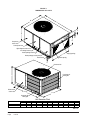
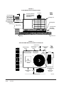
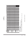
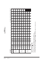
FIGURE 1
DIMENSIONS OF UNITS
W
L
A
D
E
B
Compressor
access door
Control panel door
High voltage knockout
Low voltage knockout
Heater package knockout
Supply opening
C
Heater package access panel
Drain access
Return opening
F
Condenser fan
H
Condenser air
intake grille
Blower motor
access door
47 11/16"
G
Condenser air
intake grille
Unit Dimension Chart
Unit
PA/PH1324,1330,1336
PA/PH1342,1348,1360
Supply Size
A
C
5.875
32.875
9.875
37.875
Return Size
B
C
13.875
32.875
15.875
37.875
Unit Overall Dimensions
H (height) L (length) W (width)
26.25
53.25
38.125
33.25
55.25
42.375
D
23.25
30.25
Unit General Dimensions
E
F
G
1.125
1.375
35.625
1.5
2.375
38.125
MIS-2142
Manual 2100-467D
Page
8 of 25
INSTALLATION
LOCATION
GENERAL
The unit must be located outside, or in a well ventilated
area. It must not be in the space being heated or cooled.
A sound absorbing material should be considered if the
unit is to be installed in such a position or location that
might cause transmission of sound or vibration to the
living area or adjacent buildings.
SLAB MOUNTING
A minimum of 24 inches should be provided between
the coil inlet and any building surfaces. Provide a
minimum of three feet clearance on the service access
side of the unit. See Figure 2.
TYPICAL INSTALLATIONS
1. ROOF MOUNTED – The unit is mounted on a
sturdy base on the roof of the building. Return air to
the unit is brought through a single return grille
(grilles with built-in filters are best since they enable
easy access for filter changing). Return air ducts are
attached to the lower section of the front panel.
Supply air is brought from the unit to attic duct work
or to a furred down hall. Supply air duct is attached
to the top of the front panel.
In roof top installation, as in all installations, the air
conditioner must be level from side to side.
However, the unit should have a pitch along the
length to assure complete external drainage of
precipitation and of defrost condensate.
2. CRAWL SPACE – Duct work installed in crawl
space must be well insulated and provided with a
vapor barrier. In addition, the crawl space must be
thoroughly ventilated and provided with a good
vapor barrier as a ground cover. It is most desirable
to install the unit will be outdoors rather than inside
the crawl space, so that it will be readily accessible
for service.
3. SLAB MOUNTED AT GROUND LEVEL – This
type installation is ideal for homes with a slab floor
construction where a roof mounted unit is not
desired. The supply and return duct work can be run
through a furred closet space.
4. THROUGH THE WALL – This type installation
requires a suitable framework to be fabricated
capable of withstanding the unit weight. Normally
the unit will be insulated so as to minimize supply
and return duct work.
CAUTION: All outdoor duct work must be
thoroughly insulated and weatherproofed. All
attic duct work must be thoroughly insulated.
Two inch thick insulation with suitable vapor
barrier is recommended for both outdoor and
attic runs.
Manual
Page
2100-467D
9 of 25
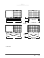
FIGURE 2
SLAB MOUNTING AT GROUND LEVEL
1 inch clearance
between duct and
any combustible
material if distance
between outside
wall and unit is less
than 3 feet (needed
on electric heat
units only).
The distance between
outside wall and unit
varies with installation
requirements.
Side
View
Air Outlet
Package Unit
Supply Duct
Mounting Slab
Return Duct
1/4 inch per foot
slope away
from building
Ground Level
Building
FIGURE 3
AIRFLOW AND SERVICE ACCESS CLEARANCES
Nearest Structure
36" min.
Compressor
Access
Control Panel
Compressor
Blower
and
Blower Motor
Blower Service
Access
Top
View
24" min.
Air Inlet
Supply and Return Ducts
Building
Heater Package
Control Panel
Access
Nearest Structure
Heater Package
Access
Condenser fan
and motor access
from top.
Leave 60" min.
above fan.
24" min.
Air Inlet
Nearest Structure
Manual 2100-467D
Page
10 of 25
MIS-2143
FIGURE 4
ELEVATED MOUNTING PLATFORM
* 12" min. if in
32°F or lower climate
48" min.
Poured concrete,
brick, or block
Platform can be as
shown or solid
Both legs must rest
on surface of platform
* 12" min. if in
32°F or lower climate
48" min.
Metal frame
Both legs must rest
on surface of platform
MIS-2144
* AS REQUIRED
Manual
Page
2100-467D
11 of 25
5. OTHER INSTALLATIONS – Many other
installations are possible with the packaged air
conditioner. No matter what the installation, always
consider the following facts:
A. Insure that the discharge air is not obstructed in
any way so as to cause operation difficulties.
B. The indoor coil drain pan is equipped with a
coupling that must be piped through a
condensate drain trap to a suitable drain.
C. Always mount the unit is such a position that it
may be easily reached for servicing and
maintenance.
D. Insure that the unit is clear so that proper air
flow over the outdoor coil will be maintained.
If this unit is operated in cooling below a 55° outdoor
ambient temperature, the installation of low ambient
controls (CMA-28) to unit is required.
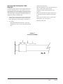
CONDENSATE DRAIN TRAP
It is very important to provide a trap in the condensate
drain line to allow a positive liquid seal in the line and
assure correct drainage from the coil condensate pan.
Install condensate drain trap shown in Figure 8. Use
drain connection size or larger. Do not operate unit
without trap. Unit must be level or slightly inclined
toward drain. With a trap installed on a unit located in
an unconditioned area, water in the trap may freeze. It
is recommended that the trap material be of a type that
will allow for expansion of water when it freezes.
Prior thought should be given to return air location and
placement of the air filter(s). The air filter(s) must be of
adequate size and readily accessible to the operator of
the equipment. Filters must be adequate in size and
properly maintained for proper operation. If this is not
done, excessive energy use, poor performance, and
multiple service problems will result. It is impossible to
oversize air filters. Generous sizing will result in
cleaner air and coils as well as lower operating costs and
extend the time between required changes. Table 5
shows minimum filter areas and recommended filter
sizes. Actual filter sizes can vary with the installation
due to single or multiple returns utilizing a filter/grille
arrangement or being placed immediately ahead of the
indoor coil face in the return air duct.
TABLE 5
FILTER REQUIREMENTS & SIZES
Model No.
Minimum Filter Area
Recommended
Siz e
PA1324
PA1330
PA1336
462 Square Inches
(3.21 Square Feet)
15 x 30-5/8 x 1
PA1342
PA1348
PA1360
608 Square Inches
(4.62 Square Feet)
(2) 16 x 20 x 1
NOTE: If roof hood accessory is to be used,
information on air filters may be found under
that heading in this manual. Air filters are
supplied as part of that package.
AIR FILTERS
Air filters for the return air side of the system are not
provided as part of these models, and must be field
supplied and installed as part of the final installation.
FIGURE 5
CONDENSATE DRAIN TRAP
Manual 2100-467D
Page
12 of 25
WIRING – MAIN POWER
Refer to the unit rating plate for wire sizing information
and maximum fuse size. Each outdoor unit is marked
with a “Minimum Circuit Ampacity”. This means that
the field wiring used must be sized to carry that amount
of current. If field installed heaters are added to the
basic unit, a second separate power supply circuit will
be required. The heater rating plate located adjacent to
the basic unit rating plate will show the appropriate
circuit ampacity fuse size, etc. (Also see “Electrical
Specifications” on pages 5 & 7.) All models are
suitable for connection with copper wire only. These
instructions must be adhered to. Refer to the National
Electrical Code for complete current carrying capacity
data on the various insulation grades of wiring material.
The electrical specifications list fuse and wire sizes
(75°F copper) for all models including the most
commonly used heater sizes.
The unit rating plate lists a “Maximum Time Delay
Fuse” or “HACR” type circuit breaker that is to be used
with the equipment. The correct size must be used for
proper circuit protection and also to assure that there
will be no nuisance tripping due to the momentary high
starting current of the compressor.
WIRING – 24V LOW VOLTAGE CONTROL
CIRCUIT
TABLE 6
THERMOSTAT WIRE SIZE
Transformer VA
55
FLA Wire Gauge
2.3
20
18
16
14
12
Maximum
Distance
In Feet
45
60
100
160
250
TRANSFORMER TAPS
230/208V, 1 phase and 3 phase equipment employ dual
primary voltage transformers. All equipment leaves the
factory wired on 240V tap. For 208V operation,
reconnect from 240V to 208V tap. The acceptable
operating voltage range for the 240 and 208V taps are:
TAP
RANGE
240
253 – 216
208
220 – 187
NOTE: The voltage should be measured at the field
power connection point in the unit and while
the unit is operating at full load (maximum
amperage operating condition).
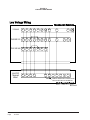
Five (5) wires should be run from thermostat subbase to
the 24V terminal board in the unit. A five conductor, 18
gauge copper, color-coded thermostat cable is
recommended. The connection points are shown in
Figure 6.
THERMOSTATS
See specific wiring information for the different models, heater KWs, and voltages on unit and heating wiring
diagrams.
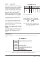
TABLE 7
WALL THERMOSTATS
Thermostat
Predominant Features
1 stage Cool; 1 stage Heat
8403-057
heat-off-cool Fan: on-auto
(TH3110D1040)
Electronic Non-Programmable
2 stage Cool; 2 stage Heat
8403-058
Electronic Non-Programmable
(TH5220D1151)
Auto or Manual changeover
8403-060
(1120-445)
3 stage Cool; 3 stage Heat
Programmable/Non-Programmable Electronic
HP or Conventional
Auto or Manual changeover
IMPORTANT NOTE: Only the thermostats as shown above will work with this equipment. The thermostats and correct
operation can be assured only by proper selection and application of these parts.
Manual
Page
2100-467D
13 of 25
FIGURE 6
LOW VOLTAGE WIRING
Low Voltage Wiring
Thermostat Subbase
1120-445
C
G
R
Y1
Y2
O
TH5220D1151
C
G
R
Y
RC
O
TH3110D1040
C
G
R
Y
RC
Unit 24V
Terminal
Block
C
G
R
Y
B
W1
E
W2
L
B
AUX
E
L
B
W
W1
W2
1
2
A
3
L
E
E
F
D
YO
REMOVE JUMPER FOR 2 STAGE ELECTRIC
HEAT ON UNITS WITH 15 OR MORE KW
Unit Control Panel
MIS-2149 B
Manual 2100-467D
Page
14 of 25
START UP
These units require R-410A refrigerant and Polyol Ester
oil.
performance. Refer to instructions for the cylinder that
is being utilized for proper method of liquid extraction.
GENERAL:
1. Use separate service equipment to avoid cross
contamination of oil and refrigerants.
SAFETY PRACTICES:
1. Never mix R-410A with other refrigerants.
2. Use recovery equipment rated for R-410A
refrigerant.
2. Use gloves and safety glasses, Polyol Ester oils can
be irritating to the skin, and liquid refrigerant will
freeze the skin.
3. Use manifold gauges rated for R-410A (800 psi/250
psi low).
3. Never use air and R-410A to leak check; the
mixture may become flammable.
4. R-410A is a binary blend of HFC-32 and HFC-125.
4. Do not inhale R-410A – the vapor attacks the
nervous system, creating dizziness, loss of
coordination and slurred speech. Cardiac
irregularities, unconsciousness and ultimate death
can result from breathing this concentration.
5. R-410A is nearly azeotropic - similar to R-22 and
R-12. Although nearly azeotropic, charge with
liquid refrigerant.
6. R-410A operates at 40-70% higher pressure than
R-22, and systems designed for R-22 cannot
withstand this higher pressure.
7. R-410A has an ozone depletion potential of zero,
but must be reclaimed due to its global warming
potential.
8. R-410A compressors use Polyol Ester oil.
9. Polyol Ester oil is hygroscopic; it will rapidly
absorb moisture and strongly hold this moisture in
the oil.
10. A liquid line dryer must be used - even a deep
vacuum will not separate moisture from the oil.
11. Limit atmospheric exposure to 15 minutes.
5. Do not burn R-410A. This decomposition
produces hazardous vapors. Evacuate the area if
exposed.
6. Use only cylinders rated DOT4BA/4BW 400.
7. Never fill cylinders over 80% of total capacity.
8. Store cylinders in a cool area, out of direct
sunlight.
9. Never heat cylinders above 125°F.
10. Never trap liquid R-410A in manifold sets, gauge
lines or cylinders. R-410A expands significantly
at warmer temperatures. Once a cylinder or line is
full of liquid, any further rise in temperature will
cause it to burst.
12. If compressor removal is necessary, always plug
compressor immediately after removal. Purge with
small amount of nitrogen when inserting plugs.
START UP NOTES
TOPPING OFF SYSTEM CHARGE
For improved start up performance, wash the indoor coil
with dishwasher detergent.
If a leak has occurred in the system, Bard
Manufacturing recommends reclaiming, evacuating
(see criteria above), and charging to the nameplate
charge. Topping off the system charge can be done
without problems.
With R-410A, there are no significant changes in the
refrigerant composition during multiple leaks and
recharges. R-410A refrigerant is close to being an
azeotropic blend (it behaves like a pure compound or
single component refrigerant). The remaining
refrigerant charge, in the system, may be used after
leaks have occurred and then “top-off” the charge by
utilizing the charging charts on the inner control panel
cover as a guideline.
REMEMBER: When adding R-410A refrigerant, it
must come out of the charging cylinder/tank as a liquid
to avoid any fractionation, and to insure optimal system
Manual
Page
2100-467D
15 of 25
START UP AND OPERATION
THREE PHASE SCROLL COMPRESSOR
START UP INFORMATION
(Model PA13361-B)
Scroll compressors, like several other types of
compressors, will only compress in one rotational
direction. Direction of rotation is not an issue with
single phase compressors since they will always start
and run in the proper direction.
However, three phase compressors will rotate in either
direction depending upon phasing of the power. Since
there is a 50-50 chance of connecting power in such a
way as to cause rotation in the reverse direction,
verification of proper rotation must be made.
Verification of proper rotation direction is made by
observing that suction pressure drops and discharge
pressure rises when the compressor is energized.
Reverse rotation also results in an elevated sound level
over that with correct rotation, as well as, substantially
reduced current draw compared to tabulated values.
Verification of proper rotation must be made at the
time the equipment is put into service. If improper
rotation is corrected at this time there will be no
negative impact on the durability of the compressor.
However, reverse operation for over one hour may have
a negative impact on the bearing due to oil pump out.
NOTE: If compressor is allowed to run in reverse
rotation for several minutes the compressor’s
internal protector will trip.
All three phase scroll compressors are wired identically
internally. As a result, once the correct phasing is
determined for a specific system or installation,
connecting properly phased power leads to the same
Fusite terminals should maintain proper rotation
direction.
The direction of rotation of the motor may be changed
by reversing any two line connections to the unit.
(Models PA13422-B, -C; PA13482-B, -C;
PA13602-B, -C)
All units with three phase scroll compressors are
equipped with a three phase line monitor to prevent
compressor damage due to phase reversal.
The phase monitor in this unit is equipped with two
LED’s. If the “Y” signal is present at the phase monitor
and phases are correct, the green LED will light.
If phases are reversed, the red fault LED will be lit and
compressor operation is inhibited.
If a fault condition occurs, reverse tow of the supply
leads to the unit. Do not reverse any of the unit factory
wires as damage may occur.
Manual 2100-467D
Page
16 of 25
SEQUENCE OF OPERATION
BLOWER ONLY – When the “Fan” switch on the
room thermostat is placed in the “On” position (circuit
R-G makes), the blower will energize and run until the
“Fan” switch is placed back into the “Auto” position.
This will allow for constant air circulation at a lower
airflow during times when the unit is not in operation
for cooling or heating.
COOLING – On a call for cooling from the room
thermostat (circuit R-Y makes), the blower will energize
(circuit R-G is automatic when R-Y makes) as well as
the compressor, and outdoor fan motor. Note that if the
“Fan” switch on the room thermostat is in the “On”
position and the blower is already in operation, then the
motor will ramp up to the required speed for cooling.
HEATING (1st Stage) – On a call for heating from
the room thermostat (circuit R-W1 makes), the blower
will energize (circuit R-G is automatic when R-W1
makes). This will place the system into heating
operation to maintain the thermostat set temperature.
Note that if the “Fan” switch on the room thermostat is
in the “On” position and the blower is already in
operation, then the motor will ramp up to the required
speed for heating.
HEATING (2nd Stage) – If the operation of the 1st
Stage electric heaters will not maintain the set room
temperature, then the thermostat will call for additional
heat to help maintain the set temperature. On a call for
second stage heating from the room thermostat (circuit
R-W2 makes), additional electric heaters will be
energized if installed.
INDOOR BLOWER MOTOR
These models feature a variable speed (ECM) motor
providing high efficiency, low sound levels and soft
start capabilities. The motor is self adjusting to provide
the proper airflow rate at duct static pressures up to
0.50" WC without user adjustment or wiring changes.
On command from the wall thermostat the motor will
start slowly and ramp up to full speed over a period of
10-15 seconds.
When the thermostat is satisfied the blower will operate
for approximately 1 minute, and then slow down and
stop.
COMPRESSOR CONTROL MODULE
The compressor control is an anti-short cycle/lockout
timer with high and low pressure switch monitoring and
alarm output.
ADJUSTABLE DELAY-ON-MAKE AND BREAK
TIMER
ADJUSTMENTS
On a call for compressor operation the delay-on-make
period begins which will be 10% of the delay-on-break
setting. When the delay-on-make is complete and the
high pressure switch (and low pressure switch if
employed) is closed, the compressor contactor is
energized. Upon shutdown, the delay-on-break timer
starts and prevents restart until the delay-on-break and
delay-on-make periods have expired.
ADJUSTABLE DELAY-ON-MAKE AND
DELAY-ON-BREAK TIMER
HIGH PRESSURE SWITCH AND LOCKOUT
SEQUENCE (Standard Feature)
If the high pressure switch opens, the compressor
contactor will de-energize immediately. The lockout
timer will go into a soft lockout and stay in soft lockout
until the high pressure switch closes and the delay-onmake time has expired. If the high pressure switch
opens again in this same operating cycle the unit will go
into manual lockout condition and the alarm circuit will
energize. Recycling the wall thermostat resets the
manual lockout.
LOW PRESSURE SWITCH, BYPASS, AND
LOCKOUT SEQUENCE (Standard Feature)
If the low pressure switch opens for more that 120
seconds, the compressor contactor will de-energize and
go into a soft lockout. Regardless the state of the low
pressure switch, the contactor will reenergize after the
delay-on-make time delay has expired. If the low
pressure switch remains open or opens again for longer
than 120 seconds the unit will go into manual lockout
condition and the alarm circuit will energize. Recycling
the wall thermostat resets the manual lockout.
ALARM OUTPUT
Alarm terminal is output connection for applications
where alarm signal is desired. This terminal is powered
whenever compressor is locked out due to HPC or LPC
sequences as described.
The potentiometer is used to select Delay-on-Break time
from 30 seconds to 5 minutes. Delay-on-Make (DOM)
timing on power-up and after power interruptions is
equal to 2 minutes plus 10% of Delay-on-Break (DOB)
setting:
0.5 minute
1.0 minute
2.0 minute
3.0 minute
4.0 minute
5.0 minute
(30 seconds)
(60 seconds)
(120 seconds)
(160 seconds)
(240 seconds)
(300 seconds)
DOB
DOB
DOB
DOB
DOB
DOB
=
=
=
=
=
=
123 second DOM
126 second DOM
132 second DOM
138 second DOM
144 second DOM
150 second DOM
LOW AMBIENT CONTROL
Optional Low Ambient Control
An optional low ambient control is available for both
factory and field installed options. The low ambient
control is to be applied to the PA13 Series models when
operation below 55° outdoor conditions are anticipated.
Without this device, the evaporating pressure would fall
off, and the indoor coil would ice over.
The fan cycling control cycles the fan motor on, once the
liquid refrigerant pressure reaches 350 psig, and off, once
it has dropped to 225 psig. It will continue to cycle
between these parameters depending on outdoor
temperatures and the load/stage of the system.
This cycling maintains a minimum liquid pressure
affecting the minimum suction pressure. This effect
insures an evaporating temperature that is slightly above
the point of ice formation on the evaporator.
This field installed option is Bard Part #CMA-28. See
Figure 7.
FIGURE 7
LOW AMBIENT CONTROL WIRING
NOTE: Both high and low pressure switch controls are
inherently automatic reset devices. The high
pressure switch and low pressure switch cut out
and cut in settings are fixed by specific air
conditioner or heat pump unit model. The
lockout features, both soft and manual, are a
function of the Compressor Control Module.
Manual
Page
2100-467D
17 of 25
SERVICE AND TROUBLESHOOTING
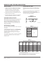
SERVICE HINTS
FAN BLADE SETTINGS
1. Caution homeowner to maintain clean air filters at
all times. Also, not to needlessly close off supply
and return air registers. This reduces airflow
through the system which shortens equipment
service life as well as increasing operating costs.
Shown in Figure 8 are the correct fan blade setting
dimensions for proper air delivery across the outdoor
coil.
2. Check all power fuses or circuit breakers to be sure
that they are the correct rating.
Any service work requiring removal or adjustment in
the fan and/or motor area will require that the
dimensions below be checked and blade adjusted in or
out on the motor shaft accordingly.
3. Periodic cleaning of the outdoor coil to permit full
and unrestricted airflow circulation is essential.
FIGURE 8
FAN BLADE SETTING
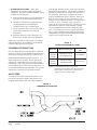
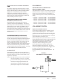
PRESSURE SERVICE PORTS
High and low pressure service ports are installed on all
units so that the system operating pressures can be
observed. Pressure tables can be found later in this
manual covering all models on cooling cycle. It is
imperative to match the correct pressure table to the
unit by model number.
"B"
“A”
REFRIGERANT CHARGE
MD-1417BC
TABLE 8
FAN BLADE SETTING DIMENSIONS
The correct system R-410A charge is shown on the unit
rating plate.
Model
You can reference Tables 10 & 11 to validate proper
system performance. However, it is recommended that
if incorrect charge is suspected, the system be
reclaimed, evacuated and charged to the nameplate
quantity and type.
Dimension "A"
PA1324
PA1330
PA1336
3¼"
PA1342
The nameplate charge quantity is optimized for thermal
performance and efficiency of this self-contained
package system.
PA1348
PA1360
TABLE 9
INDOOR BLOWER PERFORMANCE 1
MAX
ESP
2
3
4
Continuous
Airflow
Rated
Cooling
C FM
Rated
Heating
C FM
Model
Rated
ESP
PA1324
0.10
0.50
600
800
800
PA1330
0.15
0.50
750
1000
1000
PA1336
0.15
0.50
825
1100
1100
PA1342
0.20
0.50
925
1400
1400
PA1348
0.20
0.50
1025
1550
1550
PA1360
0.20
0.50
1150
1650
1650
1 Motor will deliver consistent CFM through voltage supply range with no deterioration
(197-253V for all 230/208V models).
2 Continuous CFM is the total air being circulated during continuous (manual fan) mode.
3 Will occur automatically with a call for "Y" for cooling mode operation.
4 Will occur automatically with a call for "W1" for heating mode operation.
Manual 2100-467D
Page
18 of 25
Manual
Page
2100-467D
19 of 25
Pressure
Low S i de
High Side
Low S i de
High Side
Low S i de
High Side
Low S i de
High Side
Low S i de
High Side
Low S i de
High Side
Low S i de
High Side
Low S i de
High Side
Low S i de
High Side
Return Air
Temperature
75° D B
62° WB
80° D B
67° WB
85° D B
72° WB
75° D B
62° WB
80° D B
67° WB
85° D B
72° WB
75° D B
62° WB
80° D B
67° WB
85° D B
72° WB
144
262
134
253
125
247
145
261
135
252
126
246
144
253
134
244
125
238
65°
146
288
136
278
127
271
148
284
137
274
128
267
146
278
136
269
127
262
70°
148
314
137
303
128
295
150
306
140
296
131
289
148
304
138
293
129
286
75°
149
339
139
328
130
320
153
329
142
318
133
310
151
329
140
318
131
310
80°
151
365
141
353
132
344
155
352
144
340
135
332
153
355
142
343
133
334
85°
153
391
142
378
133
369
158
375
147
362
137
353
155
380
144
367
135
358
90°
155
417
144
403
135
393
160
397
149
384
139
374
157
406
146
392
137
382
95°
157
444
146
429
136
418
163
427
151
412
141
402
159
432
148
418
138
407
(Continued on Page 20 in Table 11)
158
471
147
455
138
443
165
456
153
440
143
429
161
459
150
443
140
432
105°
160
497
149
480
139
468
167
485
156
469
145
457
163
485
151
469
142
457
110°
162
524
150
506
141
494
170
514
158
497
148
484
165
512
153
494
143
482
115°
163
551
152
532
142
519
172
543
160
525
150
512
167
538
155
520
145
507
120°
174
573
162
553
152
539
169
565
157
546
147
532
125°
Air Temperature Entering Outdoor Coil Degree F
100°
If incorrect charge suspected (more than +2 psig suction, +5 psig liquid),
it is recommended refrigerant charge be reclaimed, system evacuated and charged to serial plate quantity.
Tables based upon rated CFM (airflow) across the evaporator coil.
LOW SIDE PRESSURE +2 PSIG
HIGH SIDE PRESSURE +5 PSIG
PA1336
PA1330
PA1324
Model
COOLING
TABLE 10
PRESSURE TABLE
Manual 2100-467D
Page
20 of 25
Low S i de
High Side
Low S i de
High Side
Low S i de
High Side
Low S i de
High Side
Low S i de
High Side
Low S i de
High Side
Low S i de
High Side
Low S i de
High Side
Low S i de
High Side
75° D B
62° WB
80° D B
67° WB
85° D B
72° WB
75° D B
62° WB
80° D B
67° WB
85° D B
72° WB
75° D B
62° WB
80° D B
67° WB
85° D B
72° WB
Return Air
Pressure
Temperature
143
238
133
230
124
224
144
254
134
245
125
239
145
257
135
248
126
242
65°
144
270
134
261
125
254
145
279
135
270
127
263
147
281
137
272
128
265
70°
145
302
135
292
126
285
147
305
137
294
128
287
149
306
138
295
129
288
75°
146
334
136
323
127
315
148
330
138
319
129
311
151
330
140
319
131
311
80°
147
366
137
354
128
345
150
356
139
344
130
335
152
355
142
343
132
334
85°
148
398
138
385
129
375
151
381
141
368
132
359
154
379
143
366
134
357
90°
149
431
139
416
130
406
153
407
142
393
133
383
156
404
145
390
136
380
95°
150
457
140
442
131
431
154
436
144
421
134
410
157
434
146
419
137
409
100°
151
484
141
467
131
456
156
465
145
449
136
438
159
464
148
448
138
437
105°
152
510
141
493
132
480
158
494
147
477
137
465
160
494
149
478
140
466
110°
153
537
142
518
133
505
160
523
148
505
139
492
162
525
151
507
141
494
115°
154
563
143
544
134
530
161
552
150
533
140
520
163
555
152
536
142
523
120°
163
581
152
561
142
547
165
585
153
565
143
551
125°
Air Temperature Entering Outdoor Coil Degree F
If incorrect charge suspected (more than +2 psig suction, +5 psig liquid),
it is recommended refrigerant charge be reclaimed, system evacuated and charged to serial plate quantity.
Tables based upon rated CFM (airflow) across the evaporator coil.
LOW SIDE PRESSURE +2 PSIG
HIGH SIDE PRESSURE +5 PSIG
PA1360
PA1348
PA1342
Model
COOLING
TABLE 11
PRESSURE TABLE
– Reinsert tube into fitting.
SUCTION AND DISCHARGE TUBE
BRAZING
Compliant Scroll compressors have copper plated steel
suction and discharge tubes. These tubes are far more
rugged and less prone to leaks than copper tubes used on
other compressors. Due to different thermal properties
of steel and copper, brazing procedures may have to be
changed from those commonly used.
• To disconnect: heat joint Areas 2 and 3 slowly and
uniformly until braze material softens and the tube
can be pulled out of suction fitting. (See Figure 9.)
– Heat tube uniformly in Area 1 moving slowly to
Area 2. When joint reaches brazing
temperature, apply brazing material. (See
Figure 9)
– Heat joint uniformly around the circumference
to flow braze material completely around the
joint.
– Slowly move torch into Area 3 to draw braze
material into joint. (See Figure 9.)
– Do not overheat joint.
• To connect:
– Recommended brazing materials: silfos with
minimum 5% silver or silver braze material with
flux.
FIGURE 9
BRAZING DIAGRAM
Manual
Page
2100-467D
21 of 25
TROUBLESHOOTING GE ECM 2.3™ MOTORS
NOTE: Affects Models PA13241, PA13301, PA13361
CAUTION:
Disconnect power from unit before removing or replacing
connectors, or servicing motor. To avoid electric shock from
the motor’s capacitors, disconnect power and wait at least 5
minutes before opening motor.
Symptom
Cause/Procedure
• Noisy blower or cabinet
• Check for loose blower housing, panels, etc.
• High static creating high blower speed?
- Check for air whistling through seams in
ducts, cabinets or panels
- Check for cabinet/duct deformation
Symptom
Cause/Procedure
Motor rocks slightly
when starting
• This is normal start-up for ECM
• “Hunts” or “puffs” at
high CFM (speed)
• Does removing panel or filter reduce
“puffing”?
- Reduce restriction
- Reduce max. airflow
Motor won’t start
• No movement
• Check blower turns by hand
• Check power at motor
• Check low voltage (24 Vac R to C) at motor
• Check low voltage connections
(G, Y, W, R, C) at motor
• Check for unseated pins in connectors on
motor harness
• Test with a temporary jumper between R - G
• Check motor for tight shaft
• Perform motor/control replacement check
• Perform Moisture Check
• Motor rocks,
but won’t start
Motor oscillates up
load & down while being
tested off of blower
Motor starts, but
runs erratically
• Varies up and down
or intermittent
• Check for loose or compliant motor mount
• Make sure blower wheel is tight on shaft
• Perform motor/control replacement check
• It is normal for motor to oscillate with no
on shaft
• Check line voltage for variation or “sag”
• Check low voltage connections
(G, Y, W, R, C) at motor, unseated pins in
motor harness connectors
• Check “Bk” for erratic CFM command (in
variable-speed applications)
• Check out system controls, Thermostat
• Perform Moisture Check
Evidence of Moisture
• Motor failure or
Check
malfunction has occurred
and moisture is present
• Evidence of moisture
present inside air mover
• Perform Moisture Check
Do
Don’t
• Check out motor, controls,
wiring and connections
thoroughly before replacing
motor
• Orient connectors down so
water can’t get in
- Install “drip loops”
• Use authorized motor and
model #’s for replacement
• Keep static pressure to a
minimum:
- Recommend high
efficiency, low static filters
- Recommend keeping filters
clean.
- Design ductwork for min.
static, max. comfort
- Look for and recommend
ductwork improvement,
where necessary
• Automatically assume the motor is bad.
• “Hunts” or “puffs” at
high CFM (speed)
• Does removing panel or filter reduce
“puffing”?
- Reduce restriction
- Reduce max airflow
• Size the equipment wisely
• Stays at low CFM
despite system call
for cool or heat CFM
• Check low voltage (Thermostat) wires and
connections
• Verify fan is not in delay mode; wait until
delay complete
• “R” missing/not connected at motor
• Perform motor/control replacement check
Moisture Check
• Stays at high CFM
• “R” missing/not connected at motor
• Is fan in delay mode? - wait until delay time
complete
• Perform motor/control replacement check
• Blower won’t shut off
• Current leakage from controls into G, Y or W?
Check for Triac switched thermostat or solidstate relay
Excessive noise
• Determine if it’s air noise, cabinet, duct or
motor noise; interview customer, if necessary
• High static creating high blower speed?
- Is airflow set properly?
- Does removing filter cause blower to slow
down? Check filter
- Use low-pressure drop filter
- Check/correct duct restrictions
• Air noise
Manual 2100-467D
Page
22 of 25
• Replace motor and Perform Moisture
• Locate connectors above 7 and 4 o’clock
positions
• Replace one motor or control model # with
another (unless an authorized replacement)
• Use high pressure drop filters some have ½"
H20 drop!
• Use restricted returns
• Oversize system, then compensate with low
airflow
• Check orientation before
• Plug in power connector backwards
inserting motor connectors • Force plugs
• Connectors are oriented “down” (or as recommended by equipment
manufacturer)
• Arrange harness with “drip loop” under motor
• Is condensate drain plugged?
• Check for low airflow (too much latent capacity)
• Check for undercharged condition
• Check and plug leaks in return ducts, cabinet
Comfort Check
• Check proper airflow settings
• Low static pressure for lowest noise
• Set low continuous-fan CFM
• Use humidistat and 2-speed cooling units
• Use zoning controls designed for ECM that regulate CFM
• Thermostat in bad location?
TROUBLESHOOTING GE ECM2.3™ MOTORS
Replacing ECM Control Module
To replace the control module for the GE variable-speed indoor blower
motor you need to take the following steps:
1. You MUST have the correct replacement module. The controls are
factory programmed for specific operating modes. Even though they look
alike, different modules may have completely different functionality.
USING THE WRONG CONTROL MODULE VOIDS ALL PRODUCT
WARRANTIES AND MAY PRODUCE UNEXPECTED RESULTS.
2. Begin by removing AC power from the unit being serviced. DO NOT
WORK ON THE MOTOR WITH AC POWER APPLIED. To avoid
electric shock from the motor’s capacitors, disconnect power and wait at
least 5 minutes before opening motor.
3. It is not necessary to remove the motor from the blower assembly, nor
the blower assembly from the unit. Unplug the two cable connectors to the
motor control assembly. There are latches on each connector. DO NOT
PULL ON THE WIRES. The plugs remove easily when properly
released.
4. Locate the screws that retain to the motor control bracket to the
sheet metal of the unit and remove them. Remove two (2) nuts that
retain the control to the bracket and then remove two (2) nuts that
retain sheet metal motor control end plate. Refer to Figure 10.
5. Disconnect the three (3) wires interior of the motor control by
using your thumb and forefinger squeezing the latch tab and the
opposite side of the connector plug, gently pulling the connector. DO
NOT PULL ON THE WIRES, GRIP THE PLUG ONLY. Refer to
Figure 10.
6. The control module is now completely detached from the motor.
Verify with a standard ohmmeter that the resistance from each motor
lead (in the motor plug just removed) to the motor shell is >100K
ohms. Refer to Figure 11. (Measure to unpainted motor end plate.) If
any motor lead fails this test, do not proceed to install the control
module. THE MOTOR IS DEFECTIVE AND MUST BE
REPLACED. Installing the new control module will cause it to fail
also.
CONT’D.
7. Verify that the replacement control is correct for your
application. Refer to the manufacturer's authorized replacement list.
USING THE WRONG CONTROL WILL RESULT IN
IMPROPER OR NO BLOWER OPERATION. Orient the control
module so that the 3-wire motor plug can be inserted into the socket in
the control. Carefully insert the plug and press it into the socket until
it latches. A SLIGHT CLICK WILL BE HEARD WHEN
PROPERLY INSERTED.
8. Reverse the steps #5, 4, 3 to reconnect the motor control to the
motor wires, securing the motor control cover plate, mounting the
control to the bracket, and mounting the motor control bracket back
into the unit. MAKE SURE THE ORIENTATION YOU SELECT
FOR REPLACING THE CONTROL ASSURES THE
CONTROL'S CABLE CONNECTORS WILL BE LOCATED
DOWNWARD IN THE APPLICATION SO THAT WATER
CANNOT RUN DOWN THE CABLES AND INTO THE
CONTROL. DO NOT OVERTIGHTEN THE BOLTS.
9. Plug the 16-pin control plug into the motor. The plug is keyed.
Make sure the connector is properly seated and latched.
10. Plug the 5-pin power connector into the motor. Even though
the plug is keyed, OBSERVE THE PROPER ORIENTATION. DO
NOT FORCE THE CONNECTOR. It plugs in very easily when
properly oriented. REVERSING THIS PLUG WILL CAUSE
IMMEDIATE FAILURE OF THE CONTROL MODULE.
11. Final installation check. Make sure the motor is installed as follows:
a. Motor connectors should be oriented between the 4 o’clock
and 8 o’clock positions when the control is positioned in its
final location and orientation.
b.Add a drip loop to the cables so that water cannot enter the
motor by draining down the cables. Refer to Figure 12.
The installation is now complete. Reapply the AC power to the
HVAC equipment and verify that the new motor control module is
working properly. Follow the manufacturer’s procedures for
disposition of the old control module.
Figure 4
11
Figure
Winding Test
Figure
Figure10
3
Control Disassembly
Motor Connector
(3-pin)
Only remove
From Motor
Hex Head Bolts Push until
Latch Seats
Over Ramp
Circuit
Board
Motor
ECM 2.0
Motor OK when
R > 100k ohm
Note:
Use the shorter
bolts and
alignment pin
supplied when
replacing an
ECM 2.0
control.
Figure
Figure12
5
Drip Loop
ECM
2.3/2.5
Motor Connector
(3-pin)
Back of
Control
Connector Orientation
Between 4 and 8 o'clock
Control Connector
(16-pin)
Power Connector
(5-pin)
Hex-head Screws
Drip Loop
Manual
Page
2100-467D
23 of 25
TROUBLESHOOTING GE X13-SERIES ECM2.3™ MOTORS
NOTE: Bard Models PA13422, PA13482 & PA13602 contain the X13-Series Motors.
e. If the motor does not shut off at the end of the cycle, wait for
any programmed delays to time out (no more than 90
seconds). Also make sure that there is no call for
“Continuous Fan” on the "G" terminal.
f. If the above diagnostics do not solve the problem, confirm the
voltage checks in the next section below, then continue with
the “Model X13 Communication Diagnostics”.
If the Motor is Running
1. It is normal for the motor to rock back and forth on start up.
Do not replace the motor if this is the only problem identified.
2. If the system is excessively noisy, does not appear to change
speeds in response to a demand (Heat, Cool, Other), or is having
symptoms during the cycle such as tripping limit or freezing coil,
check the following:
a. Wait for programmed delays to time out.
b.Ensure that the motors control inputs are wired to the factory
supplied wiring diagram to insure motor is getting proper
control signals and sequencing.
c. Remove the filter and check that all dampers, registers, and
grilles are open and free flowing. If removing the filters
corrects the problem, clean or replace with a less restrictive
filter. Also check and clean the blower wheel or coil as
necessary.
d.Check the external static pressure (total of both supply and
return) to insure that you are within the ranges as listed on the
unit serial plate. If higher than allowed, additional duct work
is needed.
If the Motor is Not Running
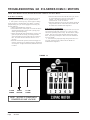
1. Check for proper high voltage and ground at the (L/L1) (G) (N/
L2) connections at the motor (see Figure 13). Correct any voltage
issues before proceeding to the next step. The X13 Motor is voltage
specific. Only the correct voltage should be applied to the proper
motor. Input voltage within plus or minus 10% of the nominal 230
VAC is acceptable.
2. If the motor has proper high voltage and ground at the (L/L1)
(G) (N/L2) connections, then continue with the “Model X13
Communication Diagnostics”.
FIGURE 13
↓
↓
L2 LINE
POWER
EARTH
GROUND
L1 LINE
POWER
NOTE: MOTOR IS CONSTANTLY
POWERED BY LINE VOLTAGE
Manual 2100-467D
Page
24 of 25
TROUBLESHOOTING GE X13-SERIES ECM2.3™ MOTORS CONT’D.
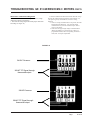
Model X13 Communication Diagnostics
The X13 motor is communicated through 24 VAC low voltage
(Thermostat Control Circuit Wiring).
1. Start with unit wiring diagram to confirm proper connections
and voltage (see Figure 14).
2. Initiate a demand from the thermostat and check the voltage
between the common and the appropriate motor terminal (1-5).
("G" input is typically on terminal #1, but refer to wiring
diagram!)
a.If the low voltage communication is not present, check the
demand from the thermostat. Also check the output
terminal and wire(s) from the terminal strip or control
relay(s) to the motor.
b.If the motor has proper high voltage as identified above
(Motor not Running #1), and proper low voltage to a
programmed terminal, and is not operating, the motor is
failed, and will require replacement.
FIGURE 14
24VAC Common
24VAC "R" Signal through
thermostat output.
24VAC Common
24VAC "R" Signal through
thermostat output.
Manual
Page
2100-467D
25 of 25