1
A. Notes for Wire Connection
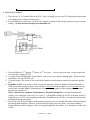
1. There are two 12 V Constant Wires in the CN1. One is to supply power to the CPU and ignition and the other
is to supply power to Starter and Accessory.
2. Pre-wired Relay for Anti-Grind - Violet at CN1 supplies a negative 250mA output when the system is remote
starting. The Yellow wire from 87a should go to the Starter Motor side.
3. Pre-wired Relay for 2nd Ignition, 2nd Starter or 2nd Accessory. You may select the relay’s trigger input from
one of the three outputs of CN2.
4. (-) Output for the Parking lights: Some vehicles, such as Jeep, have negative Parking lights. Please note that
this output is for only 250 mA. only.
5. (-) Status Output: This comes in one second before ignition on and continues until one second after ignition
off.
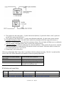
6. Light Blue of CN3: You need to tie this wire into the emergency brake for Manual Transmission Mode or
Turbo mode. Most emergency brake wires will show 12V at rest when the ignition is on or ground when you
set the brake. In either Manual Transmission or Turbo Mode, the engine will stay running for two minutes
after the key is turned off.
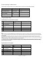
Wire Connection for Automatic Transmission vs. Manual Transmission. For manual transmission
vehicles, three additional connections are required – 1) Red/White or Red wire of CN3 to the door switch, 2)
Light Blue wire of CN3 to the emergency brake and 3) Red/Black wire of CN2 to over-ride the clutch switch
momentarily during remotestart.
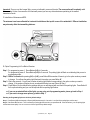
7. Glow Plug wires for diesel engines: If the negative glow plug wire sees ground, the remote starting is delayed
until this ground disappears. Likewise, if the positive glow plug wire sees positive, the remote starting is
delayed until this positive disappear. There is no programming for diesel mode. It is automatic once this wire
is used.
© Firstech, Inc. Page 3