1
(d)
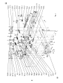
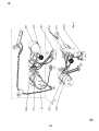
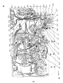
Fig. 8. Cut the negative (-) lead on the 30mfd electrolytic capacitor,
(C), the green lead to TB1- 3
U)
Fig. 8. Connect a 3 1/2" piece of
green wire from XVI 0- 8
(C) to
Fig. 8.
Cut both leads on a
1650,
5 watt resistor)' R56, to 3/4"
(C)r
Fig. 8. From the output transformer, T3, connect the yellow lead to
the green lead to TB2- 3 (S 1), the brown lead to TB2- 2 (S 1), the
(~f
(\1
(J)
and the inner conductor to TB21- 2 (C).
Fig. 8. Connect a 3 1/2" piece of orange wire from TB9-2 (C)
12. (~ Fig. 8. Strip back the outer insulation 3/4" from one end of an 8"
TB18- 2 (C).
11.
(C).
Connect the outer shield from the single conductor cable
) to TB21- 1(C)
Fig. 8.
(from ho le li
10.
Connect" 2 1/2" piece "Iced wi'e from TB9- 3 (C) to TB 11-1
Fig. S. Connect the brown lead from hole " T" to TB11- 2 (C).
9. (J) Fi ./;.
8.
I/
black lead to TB2- 1 (C), the red lead to TB5-3 (S3), the blue lead to XV9(Sl), t~e brown- yellow lead toXV10- 7(Sl)and the orange lead to TB2- 5 (S1).
TB2-4
7.
Cover one lead with a 1/2" piece of spaghetti and connect XV9-3 (S2). Connect the other lead to ground lug " E" (Sl) at XVI0. Dress resistor away from
surrounding wires.
;::; 6. (\.
5. .
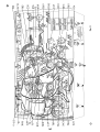
Fig. 8. Cut all leads on two 50mfd , 25V, electrolytic capacitors,
C29, and C30, to 1" . Cover the positive (+) leads on both capacitors with a
3/4"
piece of spaghetti. Connect the positive lead of one capacitor toXV10(S2) and the negative (-) lead to ground lug " C" (Sl) at XV9. Connect the
positive (+) lead of the second capacitor to XV8- 3 (52) and the negative (-)
lead to ground lug " D" (Sl) at XV7.
T8 19- 1 (C).
4.
XV8- 6 (C).
3. (V) Fig. 8. Connect a 3 1/2" piece of green wire from XV7- 6 (C) to
(S1), the brown lead to TBl- 2 (Sl), the
black lead to TB 1- 1 (C), the red lead to TB5- 3 (C), the blue lead to XV7- 7 (S H,
the bro ym- yellow lead to XV8- 7 (Sl), and the
orange lead to TBl- 5 (Sl).
TBl-4
2. ,,) Fig. 8. From the output transformer, T2, connect the yellow lead to
C39, tol 1/4" . Connect to TBI0- 1 (C).
1.
cable~ Twist the shield
the
1650,
("~t
(Sl). Dress away from
Fig. 8. Connect a 3 1/2" piece of black wire from TB8- 2 (C) to
Fig. 8. Connect a 3 1/2" piece of black wire from TBll- 3
(C) to
froM 1811-1 (C)lo TBI8-3 (C).
Fig. 8. Connect a 3 1/2" piece of orange wire from TB18- 2 (C) to
Fig. 8. Connect a 1" piece of bare wire to the dual concentric pots
XV3- 7 (S 1).
25. (\J) Fig. 8. Connect
\l/
a 1 3/4" piece of green wire from R25- 2
(51) to
24. (\J fig. 8. Connect a 2" piece of black wire from R25- 3(S2) to TB11- 3 (C).
in the rectangular hole at the middle-front of the chassis. Connect from R24(Sl) to R25::- 3 (C).
23.
C37-A (0).
22. ("' r
21. ( ) Fig. 8. Connect a 3" piece of red wire fromTB18- 3 (C) to TB15- 1 (C).
piece of red wire from TB18- 3(C) to C37-B (C).
3 1/2" p;aca "hod whoa
a 4 1/211
fg. 8. Connect"
F)g. 8. Connecta 4" piece of orange wirefromTB10- 2(C)toTB9- 2(C).
20. ('vi Fig. 8. Connect
19. ~~
18.
17. (\i)/Fig. 8. Connect the grey lead from hole " T" to XV4-2 (Sl).
ground lug n G" (C).
16.
15. (, /) Fig. 8. Connect a 3" ieceofblackwirefromTB21- 1 (C)toTBl1- 3(C).
TB21-1 (C).
14.
the surrou,nding wires.
lug R
5 watt resistor, R57, to 1 1/2"
Connect this lead to XV7- 3 (S2).
Cut the ot~er lead to 1/2" and connect to ground
and cover with a 1 1/4" piece of spaghetti.
13. (le ) Fig. 8. Cut one lead on
shield to J14, 15- 4 (51) and the inner conductor to J14, 15- 3 (Sl).
back 1/4" . Connect the
Twist the shield strands to-
gether. Strip the insulation on the inner conductor
same cable, strip the outer insulation back 1/2" .
TB21- 1 (C) and the inner conductor to
strands together.
Connect the shield to
TB21-2 (C). On the other end of the
Strip the insulation on the inner conductor back 1/4" .
piece of single conductor shielded
//