1
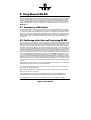
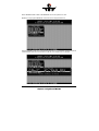
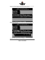
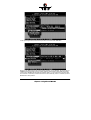
&KDSWHU' 8VLQJ 0LFURVRIW06'26 &KDSWHU'8VLQJ0LFURVRIW06'26 '8VLQJ0LFURVRIW06'26 After having explained the installation of the ICP Controller and the host-drives in chapters B and C, we now explain how to install the operating system MS-DOS. By using some examples, we shall demonstrate how to partition a host-drive, transfer MS-DOS to the hostdrive, install Windows 3.x and use a CD-ROM drive (standing for any other Not Direct Access Device) under MS-DOS. In addition, we will give you further information on how to install Windows 95. '7UDQVSDUHQF\RI+RVW'ULYHV The structure of the Host Drives, which have been installed with GDTSETUP (in chapter C), is not known to DOS. i.e., the operating system does not recognize that a given Host Drive consists of a number of hard disks forming a disk array. To DOS this Host Drive simply appears as one single SCSI hard disk with the capacity of the disk array. This complete transparency represents the easiest way to operate disk arrays under DOS; neither DOS nor the PCI computer need to be involved in the administration of these complex disk array configurations. '3DUWLWLRQLQJD+RVW'ULYHDQG7UDQVIHUULQJ06'26 You can partition the host-drives installed in chapter C with GDTSETUP as well as with the MS-DOS program FDISK. However, in our explanation we shall only use GDTSETUP. For further information on FDISK, please refer to your MS-DOS manual. During the following installation instructions we assume that there is not yet a boot disk in the computer system. Therefore, the following steps aim at installing a primary DOS partition on the host-drive previously installed with GDTSETUP (see chapter C), activating this partition, and transferring MS-DOS to this partition. Our objective is to be able to boot MS-DOS directly from this partition at the end of the installation. First of all, we would like to draw your attention to a common operating error which is often made when Host Drives are partitioned. Many users ignore that an MS-DOS boot partition has to have the state "active". If the partition is not active, the system will attempt to boot MS-DOS, but will "hang" straight away. Very often, the system message "ROM BASIC NOT FOUND, SYSTEM HALTED" is displayed (in the 40 lines of text mode). You can easily remedy this problem by booting the system from an MSDOS floppy disk, and then activating the partition with GDTSETUP (more information later in this manual) or FDISK (for more information on FDISK please refer to the MSDOS user's manual). (A) As already mentioned before, you can load GDTSETUP in two ways. For the partitioning, GDTSETUP has to be loaded from disk under MS-DOS: Boot the MS-DOS-operating system (either from a boot-floppy or from an already existing boot drive, i.e., IDE-hard disk etc.). (B) In order for GDTSETUP to work properly, you have to load the device driver GDTX000 first. This can be done in two ways: Load GDTX000 from the MS-DOS command level by typing in GDTX000<ENTER>, or load GDTX000 automatically through the CONFIG.SYS file (DEVICE=GDTX000.EXE). Load GDTSETUP from the MS-DOS command level by typing GDTSETUP<ENTER>. &KDSWHU'8VHU V0DQXDO Note: GDTSETUP.EXE as well as GDTX000.EXE are on the System Disk - DOS. (C) Now, in the program GDTSETUP, select the menu Configure Host Drives. Pressing <ENTER> leads you to the following sub-menu. In our example, the Host Drive list contains two Host Drives. The first drive in the list is not relevant for our example. &KDSWHU'8VLQJ0LFURVRIW06'26 We select this Host Drive (by moving the selection line with the cursor keys n and p) and confirm our choice with <ENTER>. Then the following screen comes up: We now select Partition Drive and then View Partitions. The following screen appears. In our example, there is no entry yet. Press <ESC>, select Create Partition and press <ENTER>. &KDSWHU'8VHU V0DQXDO In the upcoming window, select Primary Partition and confirm with <ENTER>. Now you can determine the size of the primary partition. In our example, we choose to use 1000MB of the disk capacity for the primary partition and therefore enter 1000 and simply confirm with <ENTER>. Now select View Partitions again. You can see that the primary partition has been successfully installed and has the active state (A), which is necessary to boot MS-DOS from this partition. &KDSWHU'8VLQJ0LFURVRIW06'26 (D) Now leave GDTSETUP by pressing <ESC>. After a few requests and messages from GDTSETUP, the system reboots. (E) Now use the MS-DOS program FORMAT to transfer MS-DOS to the primary partition you have just created. To do so, enter A:\> FORMAT C: /S <ENTER> (F) To complete the installation of MS-DOS, use the MS-DOS commands COPY or XCOPY to transfer the desired MS-DOS files. A different and maybe even more elegant method of installing MS-DOS is to use the SETUP program of MS-DOS versions 5 and 6. In this case, you only have to create and activate a partition with GDTSETUP or FDISK. Then boot the system from the first floppy disk delivered with MS-DOS. MS-DOS SETUP will take care of all the rest. '&21),*6<6DQGWKH'ULYHU*'7;(;( GDTX000.EXE is the high performance MS-DOS driver for all ICP Controllers. In order to obtain the best performance of the ICP Controller under MS-DOS, this driver should be listed in the first line following the HIMEM.SYS device command in the CONFIG.SYS file. When loaded, GDTX000.EXE replaces the BIOS EPROM (the so-called INT13H interface) of the ICP Controller, and also offers a VDS (Virtual DMA Services) interface. This is of particular importance for Windows 3.x. When using GDTX000.EXE please observe the following: GDTX000.EXE must be loaded from the first line following the HIMEM.SYS device command in the CONFIG.SYS file. If HIMEM.SYS is not loaded, it must be loaded from the very first line of the CONFIG.SYS file. GDTX000.EXE can be loaded in the UMA. GDTX000.EXE is needed for an optimal use of Windows 3.x. The ICP Controller unfolds its full capacity under MS-DOS or Windows 3.x only when GDTX000.EXE is installed. In order to load GDTSETUP under MS-DOS from disk, you need GDTX000.EXE In the CONFIG.SYS file, GDTX000.EXE must be loaded before GDTXDOS.EXE and GDTASPI.EXE. (Both drivers use functions contained in GDTX000.EXE). GDTXDOS.EXE (on the System Disk - DOS) is only needed if more than two hard disks connected to the ICP Controller are to be used under MS-DOS (DEVICE= GDTXDOS.EXE). For example, you have connected three hard disks to the ICP Controller and you wish to use them as DOS drives C, D, and E. Below is an example of a CONFIG.SYS file which is essential for the MS-DOS configuration device=c:\windows\himem.sys device=gdtx000.exe files=30 buffers=30 stacks=9,256 dos=high,umb &KDSWHU'8VHU V0DQXDO install=\dos\keyb.com GR,,\dos\keyboard.sys shell=\COMMAND.COM /E:512 /P device=gdtx000.exe device=mouse.sys device=\dos\setver.exe device=\dos\gdtxdos.exe device=\gdt\gdtaspi.exe device=\aspi\aswcdnec.sys /D:CD-ROM lastdrive=h In this example, besides the GDTX000 driver, the GDTXDOS.EXE driver, the GDT ASPI Manager and an ASPI Module for an NEC CD-ROM drive are loaded. '([SDQGHG0HPRU\0DQDJHUV When using Expanded Memory Managers, a certain address area has to be excluded from being controlled by these programs. This area is the GDT Dual Ported Memory address space (sized 16KB ). If the ICP Controller is not run with the GDTX000.EXE driver (that is, the driver has not been loaded from the CONFIG.SYS file), the address space of the GDT BIOS must also be excluded (the size of the GDT BIOS is 8KB). If the GDTX000.EXE driver is loaded from the CONFIG.SYS file in a line before the Expanded Memory Manager (EMM), it is not necessary to exclude the address space of the GDT BIOS. Unlike ISA or EISA computer systems where the controller’s BIOS address space is set manually (through jumpers or the configuration file), PCI computers automatically map the address space of a peripheral PCI device (e.g., the ICP Controller with its BIOS and Dual Ported Memory) to a suitable location during a warm or cold boot. If the system configuration does not change (no new PCI expansion cards are being added etc.), the PCI System BIOS will always map these two spaces to the same addresses. To help you find out where these addresses have been mapped to, the GDT BIOS indicates the physical address locations of the GDT BIOS and the GDT DPMEM during the cold boot (also see chapter B in this manual): %,26ORFDWHGDW[([())) In this example, the GDT BIOS occupies E000:0000 to E000:1FFF (E000 is the segment address). '30(0DW['['))) Here the DPMEM starts at D000:0000 and ends at D000:3FFF (D000 is the segment address). You may also use other utility programs such as Georg Schnurer’s (c’t magazine) CTPCI program in order to obtain the requested address locations. On this occasion we would like to thank Mr. Georg Schnurer and the c’t magazine for allowing us to use this very helpful utility on our system disks. Example 1: The Microsoft EMM386.EXE Manager is used. The GDT driver GDTX000.EXE has not been loaded from the CONFIG.SYS: DEVICE=EMM386.EXE X=D000-D3FF X=E000-E1FF Example 2: The Microsoft EMM386.EXE Manager is used. The GDT driver GDTX000.EXE has been loaded from the CONFIG.SYS: DEVICE=EMM386.EXE X=D000-D3FF (Note: You may have to add the path for "EMM386.EXE". Other parameters may follow the excluded areas). &KDSWHU'8VLQJ0LFURVRIW06'26 '8VLQJ:LQGRZV[ In order to be able to install Windows 3.x, a fully operational MS-DOS operating system has to be present on the chosen partition. Furthermore, the first entry in the CONFIG.SYS file behind the HIMEM.SYS line has to be: DEVICE=GDTX000.EXE (if necessary, add the correct path name after the "=" symbol and before GDTX000.EXE). (A) Now install Windows according to the instructions given in the Windows manual. Generally, you start with Disk 1 - Setup from which you load the setup program. This Setup program guides you through the entire installation and prompts you to insert further floppy disks. (B) After the installation is completed, the Setup program will ask you if you want to reset the system. This reset must be performed. (C) If you change to the directory WINDOWS after the reset and type in WIN<ENTER>, Windows will be loaded. Although thanks to its high computing power, the ICP Controller is just right for disk intensive operating systems such as Windows, it will not show its full capacity yet. The reason for this is that the "communication" between Windows and the ICP Controller is not yet carried out by GDTX000.EXE, but by Windows' SMARTDRV driver. (D) The steps in this section aim at removing SMARTDRV from the CONFIG.SYS and AUTOEXEC.BAT files, and at adding a few entries to the Windows initialization file SYSTEM.INI. Now, delete those lines from the CONFIG.SYS and AUTOEXEC.BAT files which contain SMARTDRV.EXE (one line in each file) using an editor such as EDIT for instance which is part of MS-DOS 5 and 6, or deactivate these lines by entering REM at their beginning. Then save and exit the files. Next, load the SYSTEM.INI file located in the WINDOWS directory into the editor and look for the entry [386Enh]. The following lines have to be inserted after this entry: [386Enh] EMMExclude=D000-D1FF (or according GDT DPMEM area) VirtualHDIrq=off DMABufferSize=128 Now save the file. In the line "EMMexclude=..." you have to enter the address area occupied by the GDT DPMEM. (E) Now do a warm reboot in order for the changes in the CONFIG.SYS the AUTOEXEC.BAT file to take effect. (F) Now, change to the WINDOWS directory and type in WIN<ENTER>; Windows is loaded again and the installation is completed. '8VLQJD&'520'ULYHXQGHU06'26RU:LQGRZV[ CD-ROM drives (as well as tape streamers, WORM drives and most MOD drives, too) belong to the category of the so-called Not Direct Access Devices. They cannot be installed with GDTSETUP or FDISK and FORMAT and they are not directly supported by MS-DOS or Win- &KDSWHU'8VHU V0DQXDO dows - unlike, for example, hard disks and removable hard disks. To install and access these devices, a special standard, the so-called ASPI Standard (Advanced SCSI programming Interface), has been created. While the manufacturer of the controller (in this case ICP) has to offer the ASPI Manager, the manufacturer of the SCSI device (CD-ROMs etc.) has to provide an ASPI Module (note: there are some companies which have specialized in the development of ASPI modules, for example Corel Corp. with its product corelSCSI; the ICP Controller is certified by Corel). Both units, the SCSI controller and the SCSI device, communicate through this ASPI interface. It is not a hardware interface (like, for example, Centronics, SCSI or RS232), but a pure software interface. The following illustration explains this interface: &'520 (Hardware: SCSI CD-ROM drive) 06'26:LQGRZV $63,0RGXOH (Software: driver for CD-ROM) *'7$63,0DQDJHU (GDTASPI.EXE) (Software: ASPI Manager for the ICP Controller) ,&3&RQWUROOHU (Hardware: SCSI Controller) With the following two examples we demonstrate how to install a CD-ROM drive for use with the ICP Controller under MS-DOS and Windows. The installation differs slightly, depending on whether you use the corelSCSI software or the ASW software. Regardless of which software you choose to use, the ASPI manager of the ICP Controller (located on the GDT System Disk - DOS) has to be loaded from the CONFIG.SYS file. The objective of both installations is to make the CD-ROM drive accessible as a drive (for example drive E) under MS-DOS or Windows, and to be able to access this drive just as if it were a (write-protected) floppy disk in drive A or B. At this point we presume that the CD-ROM drive has been properly connected to the ICP Controller. This includes that the SCSI-ID and the SCSI bus terminators are set in accordance with the settings of the already existing SCSI devices (i. e., the SCSI-ID chosen for the CD-ROM drive is not occupied by another device; resistor terminators are located only at the two ends of the SCSI bus). ' (([DPSOH 8 8VLQJ JWWKH H$ $6: :66RIWZDUH HIIRU UWWKH H&&'520 The important lines in both files are printed bold. CONFIG.SYS device=c:\windows\himem.sys device=gdtx000.exe files=30 buffers=30 stacks=9,256 dos=high,umb shell=\COMMAND.COM /E:512 /P device=\dos\setver.exe device=\gdt\gdtaspi.exe device=\aspi\aspicd.sys /D:CD-ROM lastdrive=h &KDSWHU'8VLQJ0LFURVRIW06'26 AUTOEXEC.BAT path=c:\;c:\dos;c:\gdt;c:\aspi; prompt $P -$G doskey c:\aspi\mscdex /D:CD-ROM The GDTX000.EXE driver is loaded from the first line following the HIMEM.SYS command of the CONFIG.SYS file. Loading the SETVER driver (part of MS-DOS) allows older versions of Microsoft's CD-ROM translation program MSCDEX (loaded from AUTOEXEC.BAT) to run trouble-free with the MS-DOS version currently installed. The next line loads the GDT ASPI Manager GDTASPI.EXE. Next, the ASPICD module for the CD-ROM drive is loaded. The parameter "/D:CD-ROM" has nothing to do with a drive name, it only serves as a recognition information for MSCDEX. As mentioned before, it is our objective to be able to access the CD-ROM drive with a drive name (i.e. E). Naturally, this drive name has to be "free", and there have to be enough drive names available. For example, the DOS command LASTDRIVE=H would enable the user to use drive names from A to H. In the AUTOEXEC.BAT file, the Microsoft translation program for CD-ROMs (MSCDEX - Microsoft CD-ROM Extension) is loaded. It is not part of MS-DOS (except for version 6). The parameter /D:CD-ROM set here has to be identical to the parameter set after the ASPICD module in the CONFIG.SYS file. After a warm reboot which serves to activate the changes made in the CONFIG.SYS and AUTOEXEC.BAT files, the CD-ROM drive can be accessed as drive E (in our example there are two SCSI hard disks in the PCI computer, and under MS-DOS they are accessed as C and D). Drive E can be accessed under Windows, too, now (the Icon next to "E" indicates that it is a CD-ROM drive). ' (([DPSOH 8 8VLQJ JFFRUHO6&6, ,IIRU UWWKH H&&'520 When using the corelSCSI software, the installation is carried out by a program (install) so that the changes in the files CONFIG.SYS and AUTOEXEC.BAT mentioned below are, to a large extent, made automatically. Under corelSCSI the SCSI/FAST-SCSI channels of the ICP Controller are available as independent host adapters. The important lines in both files are printed bold. CONFIG.SYS device=c:\windows\himem.sys device=gdtx000.exe files=30 buffers=30 stacks=9,256 dos=high,umb shell=\COMMAND.COM /E:512 /P device=\dos\setver.exe device=\gdt\gdtaspi.exe device=c:\corel\cuni_asp.sys /ID:6 /HAN:0 /N:1 /D:MSCD000 lastdrive=h AUTOEXEC.BAT path=c:\;c:\dos;c:\gdt;c:\aspi; prompt $P -$G c:\corel\corelcdx /M:8 /D:MSCD000 &KDSWHU'8VHU V0DQXDO The first line following the HIMEM.SYS command of the CONFIG.SYS file loads the GDTX000.EXE. The next line loads the GDT ASPI Manager GDTASPI.EXE. Next, the corel ASPI Module for the CD-ROM drive is loaded. The parameter "/D:MSCD000" has nothing to do with a drive name, it only serves as recognition information for CORELCDX. As mentioned before, it is our objective to be able to access the CD-ROM drive with a drive name (i.e., E). Naturally, this drive name has to be "free", and there has to be enough drive names available. For example, the command LASTDRIVE=H would enable the user to use drive names from A to H under DOS. In the AUTOEXEC.BAT file, the corel translation program for CD-ROMs, CORELCDX, is loaded. The parameter /D:MSCD000 set here has to be identical to the parameter set after the ASPI Module in the CONFIG.SYS file. After a warm reboot which serves to activate the changes made in the CONFIG.SYS and AUTOEXEC.BAT files, the CD-ROM drive can be accessed as drive E (in our example there are two SCSI hard disks in the PCI computer, and under MS-DOS they are accessed as C and D). Drive E can be accessed under Windows, too, now (the Icon next to "E" indicates that it is a CD-ROM drive). Information on the various CD-ROM drives which can be used can be obtained directly from Corel. '8VLQJD'$7'ULYHXQGHU06'26ZLWK6\WRV3OXV Sytos Plus from the company Sytron is a professional backup manager used in many system installations for backup purposes. Similarly to our last example, Sytos Plus accesses Not Direct Access Devices through the GDT ASPI Manager. In our example, we use a Wangtek 1.3GB drive. We presume that the DAT drive has been properly connected to the ICP Controller. This includes that the SCSI-ID and the SCSI bus terminators have been set in accordance with the settings of the already existing SCSI devices (i. e., the SCSI-ID set for the DAT drive is not occupied by another device; resistor terminators are located at the two ends of the SCSI bus only). Important note regarding ICP Controllers with more than one SCSI channel: Sytos Plus supports DATs, tapes, WORM drives etc. only when connected to SCSI channel A of the ICP Controller. To install Sytos Plus, proceed as follows: (A) Include the GDT driver GDTX000.EXE and the GDT ASPI Manager in the CONFIG.SYS file (if you have not done so yet). The CONFIG.SYS file now appears as follows (the important lines are printed bold): device=c:\windows\himem.sys device=gdtx000.exe files=30 buffers=30 stacks=9,256 dos=high,umb shell=\COMMAND.COM /E:512 /P device=\gdt\gdtaspi.exe (No special entries are necessary in the AUTOEXEC.BAT file). (B) Now install Sytos Plus following the Sytos Plus user's manual. (C) During the installation, select the device "Wangtek DAT/ASPI4". If Sytos Plus has already been installed before, load it and press the key combination ALT-H and F5 to select the "Wangtek DAT/ASPI4" entry from the list of DAT drives. The installation is completed now and Sytos Plus can be used with the ICP Controller. &KDSWHU'8VLQJ0LFURVRIW06'26 '1RWHVRQ$5&VRORIURP&KH\HQQH The following notes refer to the installation and the use of ARCsolo in connection with ICP Controllers. ARCsolo accesses tape back-up devices (tapes, DAT) through the ASPI interface. Consequently, the GDT ASPI Manager has to be included in the CONFIG.SYS file and the system has to be rebooted before you can install ARCsolo. The tape devices may be connected to either channel A or B (when using multi-channel ICP Controllers). Step 1: Include the GDTX000.EXE driver and the GDT ASPI Manager in the CONFIG.SYS file. The configuration file will look similar to the following listing (the relevant commands are printed bold): device=gdtx000.exe files=30 buffers=30 shell=\command.com /E:512 /P device=\gdt\gdtxdos.exe device=\gdt\gdtaspi.exe Step 2: Use ARCsolo's installation program INSTALL to transfer the ARCsolo files to the hard disk. Step 3: Change to the directory to which you have transferred the ARCsolo files (default C:\ARCSOLO) and load ARCSOLO: C:\ARCSOLO\ARCSOLO <ENTER> Step 4: The main menu with the heading Available subjects appears. Choose the item Administration and then Configure Options. Available Subjects p Administration p Configure Options Configure Tape Driver View Activity Log Step 5: On the upcoming screen, set the entry Optimize Tape Performance to No. Step 6: Next, choose the submenu Configure Tape Driver. A list of ASPI Managers appears, from which you choose Adaptec ASPI Manager and set Adapter Number: SCAN Now the installation of the ICP Controller and its ASPI Manager is completed. ARCsolo is now able to communicate with the connected tape. For further information on ARCsolo (such as creation of scripts and so on), please refer to the ARCsolo manual. &KDSWHU'8VHU V0DQXDO '7KH*'7$63,0DQDJHU*'7$63,(;( The GDT ASPI Manager GDTASPI.EXE allows you not only to run Not Direct Access Devices (e.g., CD-ROMs, tapes, MODs etc.), but to control hard disks and removable hard disks, too (the so-called Direct Access Devices). These devices are then no longer controlled by GDTSETUP but exclusively by the ASPI interface. The advantage is evident, in particular with regard to removable hard disks (for example SyQuest). When using an appropriate ASPI module to access these removable hard disks, for example ASPIDISK.SYS or UNI_ASP.SYS from Corel, you can exchange the media of these drives under DOS without having to use GDTSETUP. To the ASPI interface, the ICP Controller appears as one host-adapter (when using singlechannel ICP Controllers), or as several host-adapters (when using multi-channel ICP Controllers). Host adapter 0 (H0) corresponds to SCSI channel A, host adapter 1 (H1) to SCSI channel B, etc. . If there are more SCSI controllers (even if from various manufacturers) in the system and corresponding ASPI managers have been installed in the CONFIG.SYS file, you can determine a controller's host adapter number by using the GDT program ASPISCAN.EXE (in case of multi-channel ICP Controllers, this program also shows which host adapter numbers have been assigned to the various SCSI channels). In order to exclude that a Direct Access Device is run directly from the ICP Controller, it has to be reserved for the ASPI interface control. To do so, certain parameters have to be specified when the GDT ASPI manager is loaded: DEVICE=GDTASPI.EXE /R:Hx1Iy1[:Hx2Iy2:Hx3Iy3 ...] H: I: x1, y1: x2, y2: host adapter number SCSI ID of the SCSI device to be reserved host adapter number, SCSI ID of the first SCSI device to be reserved (in decimal form) host adapter number, SCSI ID of the second SCSI device to be reserved (in decimal form) Example: We assume that there is only one ICP Controller in the system. Two direct access devices, the SyQuest removable hard disk connected to channel A, ID 2, and the Quantum hard disk connected to channel B, ID 4, have to be reserved for the ASPI manager. The corresponding entry in the CONFIG.SYS is: DEVICE=GDTASPI.EXE /R:H0I2:H1I4 Important note: SCSI devices reserved for the ASPI manager must not have been initialized with GDTSETUP. Neither must they pertain to a GDT Logical or Host Drive. If necessary, these devices can be de-initialized with GDTSETUP. As already mentioned in paragraph 6 of this chapter, in addition to the ASPI manager an ASPI module has to be present in order to be able to access the SCSI device under MS-DOS with a drive name (e.g., D, E, etc.). In the following description you find how to install ASPI interface-reserved direct access devices with the ASW ASPI module ASPIDISK.SYS and the corelSCSI ASPI module UNI_ASP.SYS. ' 8 8VLQJ J$ $6: :$ $63,',6.6<6 Step 1: Include GDTX0000.EXE, GDTASPI.EXE with appropriate reservations (../R:..), and ASPIDISK.SYS in the CONFIG.SYS file, then do a warm reboot (Ctrl+Alt+Del). &KDSWHU'8VLQJ0LFURVRIW06'26 Step 2: Use the ASW program AFDISK.EXE to initialize the drive to be run through the ASPI interface. Step 3: After the successful initialization, do a warm reboot (Ctrl+Alt+Del). The CONFIG.SYS will be similar to the following (the relevant entries are printed bold): device=gdtx000.exe files=30 buffers=30 stacks=9,256 shell=\COMMAND.COM /E:512 /P device=\gdt\gdtxdos.exe device=\gdt\gdtaspi.exe /R:H1I4 device=aspidisk.sys Note: Drives run with ASPIDISK.SYS are not compatible with drives run with GDTSETUP. ' 8 8VLQJ JFFRUHO6&6, Step 1: Include GDTX0000.EXE, GDTASPI.EXE with appropriate reservations (../R:..) in the CONFIG.SYS file, then do a warm reboot (Ctrl+Alt+Del). Step 2: Load corel’s Install program and follow the instructions. Preferably, use Express-Setup. Step 3: After the successful installation, do a warm reboot (Ctrl+Alt+Del). Step 4: Using the corelSCSI program CFORMAT, format the drive to be run through the ASPI interface. The CONFIG.SYS will be similar to the file below (the relevant entries are printed bold). The parameters following the corelSCSI driver refer to a particular configuration, they have automatically been added by the corelSCSI INSTALL program. device=gdtx000.exe files=30 buffers=30 stacks=9,256 shell=\COMMAND.COM /E:512 /P device=\gdt\gdtxdos.exe device=\gdt\gdtaspi.exe /R:H1I4 device=\coreldrv\UNI_ASP.SYS /C:4 /ID:4;;;1 /VOL:1 /DOS4 /SS:512 /@4:-98 Note: Drives run with corelSCSI and the UNI_ASP.SYS driver are neither compatible with drives run with GDTSETUP and the GDT cache nor with those run with the above mentioned ASPIDISK.SYS driver. ',QVWDOOLQJ:LQGRZV To install Windows 95, a fully operational MS-DOS operating system is needed on the partition on which Windows 95 is to be installed. Furthermore, you need a CD-ROM that is fully accessible under MS-DOS and connected to the ICP Controller. For further details, please refer to section D.6 of this chapter. The CONFIG.SYS file must at least include the entries for GDTX000.EXE, GDTASPI.EXE and the ASPI module (e.g., ASPICD). Step 1 Disable the Delayed Write Cache of the ICP Controller. To do so use the GDTSETUP program, or the GDTMON program. &KDSWHU'8VHU V0DQXDO Step 2 Install Windows 95 following to the instructions given by the Windows 95 installation software. Windows 95 uses the INT13H BIOS functions to access the Host Drives of the ICP Controller. Step 3 This step aims on the installation of the GDT high performance Windows 95 driver, called GDTX.MPD. Once it is installed and activated, it replaces the restricted INT13H BIOS functions. 1. Boot Windows 95 2. Click the 6WDUW button on the Windows 95 task bar and then select 6HWWLQJV 3. Click the &RQWURO3DQHO 4. Double click the 6\VWHP Icon 5. Click the 'HYLFH0DQDJHU 6. Double click 2WKHU'HYLFHV 7. Double click 3&,6&6,%XV&RQWUROOHU 8. Click 'ULYHU 9. Click &KDQJH'ULYHU 10.Double Click 6&6,&RQWUROOHUV 11.Click +DYH'LVN 12.Insert the GDT Windows 95 driver disk 13.Click 2. 14.Select the *'76&6,'LVN$UUD\&RQWUROOHU 15.Click 2. 16.Click 2. 17.Never click 7HVW but &DQFHO. Windows 95 is not able to determine if the GDT BIOS can be removed. Therefore, do not use the 7HVW option and select &DQFHO. Otherwise, the system might freeze. 18.Remove the GDT Windows 95 driver disk. 19.Restart the computer. Step 4 Enable the Delayed Write Cache of the ICP Controller. To do so use the GDTSETUP program, or the GDTMON program. &KDSWHU'8VLQJ0LFURVRIW06'26 This page is intentionally left blank. &KDSWHU'8VHU V0DQXDO