1
1
8VHU
V0DQXDO$GGHQGXP
,&3&RQWUROOHUVRIWKH*'75'6HULHV
3&,:LGH8OWUD6&6,
5$,'&RQWUROOHUV
(GLWLRQ
&RS\ULJKW
,&3YRUWH[&RUSRUDWLRQ
:HVW9DQ%XUHQ6WUHHW
3KRHQL[$=86$
,&3YRUWH[&RPSXWHUV\VWHPH*PE+
)DOWHUVWUDVVH
)OHLQ*HUPDQ\
$OO5LJKWVDQG&KDQJHV5HVHUYHG
2
3
&RQWHQWV
V
2
2YHUYLHZ
&KDSWHU,
&KDSWHU,,
&KDSWHU,,,
&KDSWHU,9
&KDSWHU9
8VLQJ,%026Y[
8VLQJ6&281,;9
8VLQJ,QWHUDFWLYH81,;
8VLQJ8QL[:DUH
*'76(783LQ'HWDLO
4
/LPLWHG
G:
:DUU
UUD
DQW\
,&3YRUWH[&RUSRUDWLRQ,&3YRUWH[JXDUDQWHHVWKDWWKLVSURGXFWLVIUHHIURPGHIHFWVLQPDWHULDODQG
ZRUNPDQVKLS6XEMHFWWRWKHFRQGLWLRQVDQGOLPLWDWLRQVVHWIRUWKEHORZ,&3YRUWH[ZLOODWLWVRZQ
RSWLRQHLWKHUUHSDLURUUHSODFHDQ\SDUWRIWKLVSURGXFWZKLFKSURYHVWREHGHIHFWLYHE\UHDVRQVRI
LPSURSHUZRUNPDQVKLSRUPDWHULDOV3DUWVXVHGWRUHSDLUSURGXFWVRUUHSODFHPHQWSUR GXFWVZLOOEH
SURYLGHGE\,&3YRUWH[RQDQH[FKDQJHEDVLVDQGZLOOEHHLWKHUQHZRUUHIXUELVKHGWREHIXQFWL R
QDOO\HTXLYDOHQWWRQHZ
7KLVZDUUDQW\GRHVQRWFRYHUDQ\GDPDJHWRWKLVSURGXFWZKLFKUHVXOWVIURPDFFLGHQWDEXVHPLV X
VHQDWXUDORUSHUVRQDOGLVDVWHU$FWVRI*RGRUDQ\XQDXWKRUL]HGGLVDVVHPEO\UHSDLURUPRGLILFDW L
RQ7KHGXUDWLRQRIWKLVZDUUDQW\LVRQH\HDUIURPWKHGDWHRIRULJLQDOUHWDLOSXUFKDVH
:DUU
UUD
DQW\
\&
&ODLP
P5
5HTXLUHPHQWV
7RREWDLQZDUUDQW\VHUYLFHUHWXUQWKHGHIHFWLYHSURGXFWIUHLJKWSUHSDLGDQGLQVXUHGWR\RXUORFDO
DXWKRUL]HG,&3YRUWH[GHDOHURUGLVWULEXWRURUWR,&3YRUWH[&RUSRUDWLRQ:HVW9DQ%XUHQ
6WUHHW3KRHQL[$=3OHDVHQRWHWKHIROORZLQJ<RXPXVWLQFOXGHWKHSURGXFWVHULDOQXPEHU
DQGD
GHWDLOHGGHVFULSWLRQRIWKHSUREOHP\RXDUHH[SHULHQFLQJ<RXPXVWDOVRLQFOXGHSURRIRIWKHGDWHRI
RULJLQDOUHWDLOSXUFKDVHDVHYLGHQFHWKDWWKHSURGXFWLVZLWKLQWKHZDUUDQW\SHULRG
,I\RXQHHGWRUHWXUQWKHSURGXFWWR,&3YRUWH[\RXPXVWILUVWREWDLQD5HWXUQ0DWHULDO$XWKRUL]DWLRQ
50$QXPEHUE\FDOOLQJ,&3YRUWH[&RUSRUDWLRQDW7KLV50$QXPEHUPXVWEHGL V
SOD\HGRQWKHRXWVLGHRI\RXUSDFNDJH3URGXFWVPXVWEHSURSHUO\SDFNDJHGWRSUHYHQWGDPDJHLQ
WUDQVLW,&3YRUWH[DFFHSWVQRUHVSRQVLELOLW\IRUSURGXFWVZKLFKDUHGDPDJHGRQDUULYDOGXHWRSRRU
IUHLJKWVHUYLFH
'LVFODLPHUV
7KHIRUHJRLQJLVWKHFRPSOHWHZDUUDQW\IRU,&3YRUWH[SURGXFWVDQGVXSHUVHGHVDOORWKHUZDUUDQWLHV
DQGUHSUHVHQWDWLRQVZKHWKHUZULWWHQRURUDO([FHSWDVH[SUHVVO\VHWIRUWKDERYHQRRWKHUZDUUDQWLHV
DUHPDGHZLWKUHVSHFWWR,&3YRUWH[SURGXFWV,&3YRUWH[H[SUHVVO\GLVFODLPVDOOZDUUDQWLHVQRWVWDWHG
KHUHLQLQFOXGLQJWRWKHH[WHQWSHUPLWWHGE\DSSOLFDEOHODZDQ\LPSOLHGZDUUDQW\RIPHUFKDQWDELOLW\
RUILWQHVVIRUDSDUWLFXODUSXUSRVH,QQRHYHQWZLOO,&3YRUWH[EHOLDEOHWRWKHSXUFKDVHURUWRDQ\
XVHURIWKH,&3YRUWH[SURGXFWIRUDQ\GDWDORVVGDWDFRUUXSWLRQGDPDJHVH[SHQVHVORVWUHYHQXHV
ORVW
VDYLQJVORVWSURILWVRUDQ\RWKHULQFLGHQWDORUFRQVHTXHQWLDOGDPDJHVDULVLQJIURPWKHSXUFKDVH
XVHRULQDELOLW\WRXVHWKH,&3YRUWH[SURGXFWHYHQLI,&3YRUWH[KDVEHHQDGYLVHGRIWKHSRVVLELOLW\RI
VXFKGDPDJHV
,&3YRUWH[LVQRWOLDEOHIRUDQGGRHVQRWFRYHUXQGHUZDUUDQW\DQ\FRVWVDVVRFLDWHGZLWKVHUYLFLQJ
DQGRULQVWDOODWLRQRI,&3YRUWH[SURGXFWV
7KLVPDQXDOKDVEHHQYDOLGDWHGDQGUHYLHZHGIRUDFFXUDF\7KHVHWVRILQVWUXFWLRQVDQGGHVFULSWLRQV
ZHUHDFFXUDWHIRU,&3'LVN$UUD\&RQWUROOHUVDWWKHWLPHRIWKLVPDQXDO·VSU RGXFWLRQ+RZHYHU
VXFFHHGLQJ&RQWUROOHUVVRIWZDUHDQGPDQXDOVDUHVXEMHFWWRFKDQJHZLWKRXWQRWLILFDWLRQ7KHUHIRUH
,&3YRUWH[DVVXPHVQROLDELOLW\IRUGDPDJHVLQFXUUHGGLUHFWO\RULQGLUHFWO\IURPHUURUVRPLVVLRQVRU
GLVFUHSDQFLHVEHWZHHQWKH&RQWUROOHUVRIWZDUHDQGWKHPDQXDO
5
3LFNXSWKHSKRQH
LI\RXQHHGWHFKQLFDOVXSSRUW
DQGGLDOWKHQXPEHUV
)RU(XURSH
)RUWKH86$
RUVHQGXVD)$;
)RU(XURSH
)RUWKH86$
RUVHQGXVDQ(0DLO
)RU(XURSHVXSSRUW#YRUWH[GH
)RUWKH86$VXSSRUW#LFSYRUWH[FRP
RUFDOORXU%%61
K
RUFKHFNRXU:HEVLWH
KWWSZZZLFSYRUWH[FRP
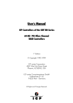
6
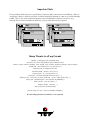
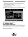
Important Note
Using modern RAID Systems significantly increases data security and availability. Under no
circumstances does it relieve you from a careful and daily backup on tape or a similar backup
media. This is the only method to protect your valuable data against total loss (e.g.,
through fire or theft), accidental deletion, or any other destroying impacts.
Many Thanks to all my Friends
Monika & Wolfgang (the grandmasters)
AnnDee, Lois, Ken and Andreas (the Phoenix Crew)
Achim, Dieter, Günter, Norbert, Otto, Ralph, Sam, Steffen, Wolfgang (WOS), (real wizards)
Alfred (AB, "We need ultra2. I say we have it")
Andreas (AK, or "Kopf nur mit ö")
Michael (Mipf, "where is my CPU ?")
Jürgen (Jogo, "Hi, is Jurgen there ?")
Ruth (RA, "she had to proof-read that thing, ...)
Johannes (JS, "I want my ice with a red cap .., or Dr. Oops-Click-Click...")
Jürgen (JB, "diesbezüglich & hinsichtlich or probably")
Klaus (KLM, "..not an Airline..")
Markus (Malu, "Luuuuu....")
Uwe (5 Paninis for Reinhardt)
All the fantastic "rest" of this incredible company.
It is not only a pleasure to work here, it is a passion.
7
)&&&
&&&R
RPSOLOLD
DQFH6WDWHPHQW
,QIRUPDWLRQIRUWKH8VHU
127(7KLVHTXLSPHQWKDVEHHQWHVWHGDQGIRXQGWRFRPSO\ZLWKWKHOLPLWVIRUD&ODVV%
GLJLWDOGHYLFHSXUVXDQWWR3DUWRIWKH)&&5XOHV7KHVHOLPLWVDUHGHVLJQHGWRSURYLGH
UHDVRQDEOHSURWHFWLRQDJDLQVWKDUPIXOLQWHUIHUHQFHLQUHVLGHQWLDOLQVWDOODWLRQV7KLVHTXLS
PHQWJHQHUDWHVXVHVDQGFDQUDGLDWHUDGLRIUHTXHQF\HQHUJ\DQGLIQRWLQVWDOOHGDQGXVHG
LQDFFRUGDQFHZLWKWKHLQVWUXFWLRQVPD\FDXVHKDUPIXOLQWHUIHUHQFHWRUDGLRFRPPXQLFD
WLRQV+RZHYHUWKHUHLVQRJXDUDQWHHWKDWLQWHUIHUHQFHZLOOQRWRFFXULQDSDUWLFXODULQVWDO
ODWLRQ,IWKLVHTXLSPHQWGRHVFDXVHKDUPIXOLQWHUIHUHQFHWRUDGLRRUWHOHYLVLRQUHFHSWLRQ
ZKLFKFDQEHGHWHUPLQHGE\WXUQLQJWKHHTXLSPHQWRIIDQGRQWKHXVHULVHQFRXUDJHGWR
WU\WRFRUUHFWWKHLQWHUIHUHQFHE\RQHRUPRUHRIWKHIROORZLQJPHDVXUHV
5HRULHQWDWHRUUHORFDWHWKHUHFHLYLQJDQWHQQD
,QFUHDVHWKHVHSDUDWLRQEHWZHHQWKHHTXLSPHQWDQGWKHUHFHLYHU
3OXJWKHHTXLSPHQWLQWRDQRXWOHWRQDFLUFXLWGLIIHUHQWIURPWKDWWRZKLFKWKHUHFHLYHULV
SRZHUHG
,IQHFHVVDU\FRQVXOWWKHGHDOHURUDQH[SHULHQFHGUDGLR79WHFKQLFLDQIRUDGGLWLRQDO
VXJJHVWLRQV
7KHXVHRIDQRQVKLHOGHGLQWHUIDFHFDEOHZLWKWKHUHIHUHQFHGGHYLFHLVSURKLELWHG
&KDQJHVRUPRGLILFDWLRQVQRWH[SUHVVO\DSSURYHGE\,&3YRUWH[&RPSXWHUV\VWHPH*PE+
FRXOGYRLGWKHDXWKRULW\WRRSHUDWHWKHHTXLSPHQW
8
&RQWHQWV
,86,1*,%0269(56,21;$1':$53 ,7UDQVSDUHQF\RI+RVW'ULYHV ,3UHSDULQJWKH,QVWDOODWLRQ ,&DUU\LQJRXWWKH,QVWDOODWLRQ
,8VLQJD&'520'ULYHXQGHU26
,,QVWDOODWLRQZLWK266&6,'0' ,,QVWDOODWLRQZLWK26$63,'0' ,&RPPDQG/LQH6ZLWFKHVRI*'7;$'' ,,86,1*6&281,;9 ,,7UDQVSDUHQF\RI+RVW'ULYHV
,,*HQHUDO7LSVIRU,QVWDOODWLRQ
,,,QVWUXFWLRQVRQPNGHY$'0IRUY[
,,,QVWUXFWLRQVRQPNGHY$'0IRUY[2SHQ6HUYHU ,,)XUWKHU,QIRUPDWLRQ ,,,86,1*,17(5$&7,9(81,; ,,,7UDQVSDUHQF\RI+RVW'ULYHV
,,,,QVWDOODWLRQDVDQDGGLWLRQDO&RQWUROOHU ,,,,QVWDOODWLRQDV%RRW&RQWUROOHU ,,,81,;7DUJHW,'/81RID+RVW'ULYH1XPEHU ,,,)XUWKHU,QIRUPDWLRQ ,986,1*81,;:$5(
,97UDQVSDUHQF\RI+RVW'ULYHV ,9*HQHUDO,QVWDOODWLRQ1RWHV ,9*'7DV%RRW&RQWUROOHU ,9*'7DVDQDGGLWLRQDO&RQWUROOHU ,9&RRUGLQDWHVRI6&6,GHYLFHV ,9)XUWKHU,QIRUPDWLRQ 9*'76(783,1'(7$,/ 97KHIRXU/HYHOVRI+LHUDUFK\LQWKH*'7)LUPZDUH 9+RVW'ULYH7\SHVLQ5$,'<1( 9
96&6,'HYLFHV:KLFKFDQEH&RQILJXUHG:LWK*'76(783 9/RDGLQJ*'76(783
96SHFLDO.H\VLQ*'76(783
9([SUHVV6HWXS 96HOHFW&RQWUROOHU
9&RQILJXUH&RQWUROOHU
9&RQWUROOHU6HWWLQJV 9)LUPZDUH8SGDWH
9&RQILJXUH3K\VLFDO'HYLFHV 96&6,3DUDPHWHU,QLWLDOL]H 9)RUPDW'LVN 9&KHFN6XUIDFH
99LHZ'HIHFWV6WDWXV
9'HLQLWLDOL]H'LVN
9/RFN8QORFN'LVN 9&RQILJXUDWLRQRI6$)7(6XEV\VWHPV 9&RQILJXUH/RJLFDO'ULYHV 9,QVWDOOLQJD/RJLFDO'ULYHRIWKH7\SH'LVN 9,QVWDOOLQJD/RJLFDO'ULYHRIWKH7\SH&KDLQ 9&RQILJXUH$UUD\'ULYHV 91RWHVRQWKH&RQILJXUDWLRQRI$UUD\V'ULYHV 9&KDQJH'ULYH1DPH
9([SDQG$UUD\'ULYH 9$GG5$,'&RPSRQHQW 95HSODFH$UUD\&RPSRQHQW 95HPRYH5$,'&RPSRQHQW
95HPRYH$UUD\'ULYH 9$GG+RW)L['ULYH 95HPRYH+RW)L['ULYH
9+RW)L[3RRO$FFHVV 93DULW\9HULI\ 93DULW\5HFDOFXODWH 9%XLOG5HEXLOG3URJUHVV 9&RQILJXUH+RVW'ULYHV 9&KDQJH'ULYH1DPH
96ZDS+RVW'ULYHV
95HPRYH+RVW'ULYH 96SOLW+RVW'ULYH
10
90HUJH+RVW'ULYHV 93DUWLWLRQ+RVW'ULYH
92YHUZULWH0DVWHU%RRW&RGH 96DYH,QIRUPDWLRQ 9/HDYLQJ*'76(783 ,QGH[ 11
&KDSWHU,
8VLQJ
J2
26
12
,8VLQJ,%0269HUVLRQ[DQG:DUS
After having exposed the installation of the ICP Controller in chapters B and C as well as
that of the host-drives, we would now like to give you some hints and pieces of advice on
how to install IBM's operating system OS/2 Versions 2.x and Warp. Furthermore, we explain
how to install a CD-ROM drive (representatively standing for any other Not Direct Access Device) under OS/2.
,7UDQVSDUHQF\RI+RVW'ULYHV
The structure of the Host Drives, which have been installed with GDTSETUP (in chapter C),
is not known to OS/2. I.e., the operating system does not recognize that a given Host Drive
consists of a number of hard disks forming a disk array. To OS/2, this Host Drive simply appears as one single hard disk with the capacity of the disk array. This complete transparency represents the easiest way to operate disk arrays under OS/2; neither OS/2 nor the PCI
computer need to be involved in the administration of these complex disk array configurations.
,3UHSDULQJWKH,QVWDOODWLRQ
Under OS/2, the ICP Controller can be operated in two different ways. It is either run by
GDT's BIOS (INT13H interface), or, alternatively, by the high performance driver
GDTX000.ADD (located on the GDT OS/2 disk). Correspondingly, there are two different
ways of installing OS/2 with the ICP Controller. At this point we would like to stress that
only by using the high performance GDTX000.ADD driver can the ICP Controller unfold its
full capacity under OS/2. We therefore recommend this operating mode. In order to be able
to use the GDTX000.ADD from the very beginning of the installation it has to be copied to
the OS/2 diskette #1. We recommend the following procedure:
6WHSWith MS-DOS (using DISKCOPY for example), create a copy of the OS/2 diskette #1.
6WHSCopy GDTX000.ADD (using the COPY command) into the root directory of this new
floppy disk. To get sufficient free space on OS/2 diskette # 1, it may be necessary to erase
some files which are not needed for the installation procedure (for example not needed
*.ADD files)
6WHSInsert the following line into the OS/2 CONFIG.SYS file of your DISK 1 copy:
BASEDEV=GDTX000.ADD /V
The position of the entry is irrelevant.
,&DUU\LQJRXWWKH,QVWDOODWLRQ
As the OS/2 installation takes quite a long time, we suggest having a closer look at the
OS/2 installation manual. During the installation you will be prompted to answer several
questions, for example whether you want to copy OS/2 on an already existing MS-DOS partition, or whether you want OS/2 to have its own partition, or whether you want to install
the OS/2 Boot-Manager, etc. . After having decided on these options, you can start the installation beginning with DISK 1 of the copy set you have previously created.
The OS/2 installation itself is carried out according to the OS/2 installation program.
After having completed the installation, you should check that the OS/2 CONFIG.SYS file
created during the OS/2 installation contains the following line:
13
BASEDEV=GDTX000.ADD /V
and that the driver GDTX000.ADD is either in the OS/2 or the root directory:
GDTX000.ADD
\OS2\GDTX000.ADD
or
If this line is missing you have to add it to your CONFIG.SYS file. If the GDT driver
GDTX000.ADD is not in the OS/2 or root directory, copy it there.
,8VLQJD&'520'ULYHXQGHU26
If OS/2 has been installed from an OS/2 CD, you may skip this chapter as well as chapters
I.4.1 and I.4.2. A CD-ROM drive (standing for any other Not Direct Access Device) can be accessed under OS/2 either directly through the OS/2 driver OS2SCSI.DMD, or the OS/2 ASPI
Manager OS2ASPI.DMD, or, for example, through corelSCSI for OS/2. We presume that the
CD-ROM drive has been properly connected to the ICP Controller. This includes that the
SCSI-ID and the SCSI bus terminators are set in accordance with the settings of the already
present SCSI devices (i. e., the SCSI-ID set for the CD-ROM drive is not occupied by another
device; resistor terminators are located at the two ends of the SCSI bus only).
,,QVWDOODWLRQZLWK266&6,'0'
6WHS Click the OS/2 System icon on the OS/2 Presentation Manager. Then select "System
Setup" and then "Selective Install".
6WHS Confirm the system configuration with "OK".
6WHS Now click "CD-ROM Device Support" in the window opening and select the CD-ROM
drive. Hereafter click "OK".
6WHS Click Install now and the installation begins. The system will ask you to insert further
OS/2 system disks or select an appropriate path on the hard disk.
6WHS After the installation is completed and OS/2 is started again, the CD-ROM drive can
be accessed.
,,QVWDOODWLRQZLWK26$63,'0'
6WHS Add the following line to the CONFIG.SYS file, using, for example, the OS/2 system
editor:
BASEDEV=OS2ASPI.DMD
6WHS Now the driver GDTX000.ADD has to be configured in a manner that allows only the
ASPI Manager to access the CD-ROM drive (identified by its SCSI-ID, which in our example
is SCSI-ID 6):
BASEDEV=GDTX0000.ADD /V /A:0 /AM:(0,6)
(an exact description of the command line switches can be found in the next chapter, I.5).
6WHS Now install the corelSCSI software from the corelSCSI OS/2 floppy disk.
6WHS After the restart of OS/2, the CD-ROM drive can be accessed.
14
,&RPPDQG/LQH6ZLWFKHVRI*'7;$''
The GDTX000.ADD driver can be configured with the following command line switches. The
names of the switches are IBM OS/2 compliant. The descriptions given in brackets ([,]) are
optional. The "!" inverts the following function.
%$6('(9 *'7;$''>9@>$G@>>@'0@>>@60@>>@$0@>126&$1@>>@87@>5@
9
Verbose (only possible as first parameter)
Display logo/error messages on screen.
$G
All the following options until the next /A:d
are valid for adapter d. All adapters are numbered
starting with 0.
>@'0
Switch for supporting a Direct Access
[SCSI] Device-Manager (i.e.: OS2DASD.DMD)
Support Host-Drives (Standard)
'0
Support Host-Drive d as a hard disk
'0G
(default if no CD-ROM is present)
Support SCSI device (Bus d, SCSI-ID e)
'0GH
as a hard disk (default for SCSI type 0: DASD)
>@60
Switch for supporting a SCSI-Manager
(i.e.: OS2SCSI.DMD)
Support SCSI devices (default)
60
Support Host-Drive d as SCSI device
60G
(default if d is a cached CD-ROM)
Support SCSI device (Bus d, SCSI-ID e)
60GH
as SCSI device (default for all SCSI types
except 0: DASD)
>@$0
Switch for supporting an ASPI-Manager
(i.e.: OS2ASPI.DMD)
Support SCSI devices (OS2ASPI.DMD)
$0
Support Host-Drive d as ASPI-Device
$0G
Support SCSI device (Bus d, SCSI-ID e)
$0GH
as ASPI-Device
126&$1
>@87
that are
5GH
Scans the SCSI channels only for these devices,
which are configured through the "/DM“, „/SM“, „/AM“
or „/R“ switches.
Ignores special time-out values of a certain
application, but always uses the GDTX000.ADD
settings. Some backup programs use time-out values
too short.
Reserve a SCSI device (channel d, SCSI-ID e) as a raw
device, which is directly operated through OS/2 (the
data are not cached by the GDT cache). This SCSIdevice must not be initialized with GDTSETUP
(it may need to be de-initialized).
If reciprocally exclusive options have been selected, the one set last is effective.
15
&KDSWHU,,
8VLQJ
J6
6&2
28
81,;
16
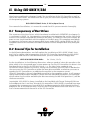
,,8VLQJ6&281,;9
After having explained in chapters B and C the installation of the ICP Controller as well as
that of the Host Drives, we would now like to give you a few hints regarding the installation
of the operating systems
SCO UNIX V/386 3.2v4.x, 3.2v5.x (Open Server)
For successful installation, it is essential to read the SCO system manuals thoroughly.
,,7UDQVSDUHQF\RI+RVW'ULYHV
The structure of the Host Drives, which have been installed with GDTSETUP (in chapter C),
is not known to UNIX. I.e., the operating system does not recognize that a given Host Drive
consists of a number of hard disks forming a disk array. To UNIX this Host Drive simply appears as one single hard disk with the capacity of the disk array. This complete transparency represents the easiest way to operate disk arrays under UNIX; neither UNIX nor the PCI
computer need to be involved in the administration of these complex disk array configurations.
,,*HQHUDO7LSVIRU,QVWDOODWLRQ
In the following description, we shall explain the installation of SCO UNIX V/386 3.2v4.x
and 3.2v5.x step by step in connection with the ICP Controller. Apart from the SCO UNIX
floppy disks and the SCO UNIX documentation, you also need the GDT floppy disks
GDT SCO UNIX BTLD-Disks
for 3.2v4.x, 3.2v5.x
for the installation. In the following discussion, when we speak of a boot drive we refer to the
drive which is first integrated upon system power up. For the ICP Controller this drive is the
first Host Drive in the list of GDT Host Drives, i. e., the Host Drive number 0 (see
GDTSETUP menu Configure Host-Drives). During the installation you will have to decide whether you want the ICP Controller to make the boot drive available, or whether you want to
operate the ICP Controller as an additional controller in the computer system.
If the ICP Controller is the only hard disk controller in the computer system, it will automatically make the boot drive available. If there are more hard disk controllers, the controller
which makes the first drive available (the drive containing the MS-DOS partition C:) will be
the boot controller.
In principle, SCO UNIX is always installed on the hard disk with Target ID 0 and LUN 0 on
host adapter 0, that is on Host Drive 0 of this controller. If SCO UNIX is installed from tape
(streamer) the streamer must have SCSI ID 2 and be connected to SCSI channel A of host
adapter 0. For an installation from CD-ROM, the CD-ROM device must have SCSI-ID 5 and
has to be connected with channel A of the ICP Controller.
17
When using 3.2v4.x or 3.2v5.x, you have the option to link the driver to the kernel before
starting the kernel (btld (ADM)). This will allow you to use the ICP Controller as the only
controller in the system. Use the GDT BTLD Disk. During the installation, whenever the N1
floppy disk is inserted and the message
Boot
:
is displayed, do not press <ENTER> immediately, but type in link <ENTER>. The system
will then prompt you for the name of the BTLD driver. Now type in gdth. It may be necessary
to type in the complete boot string. In this case, you have to add the following command:
link=gdth btld=fd(xx)
where xx is the "Minor Device Number" of the corresponding device file. xx = 60 for
fd0135ds18, 3,5" floppy as A,: or xx = 61 for fd1135ds18, 3,5" floppy as B: (see SCO UNIX
system Administrator's Reference, Hardware Dependence, floppy devices). When requested, enter the IRQ which has been assigned to the PCI INT of the ICP Controller (see chapter B, Hardware Installation). In addition, the GDT BIOS must not be disabled and the boot
drive must be connected with the ICP Controller having the lowest PCI slot number.
When the UNIX installation has been completed, the driver is installed, too, and you may
install further devices with mkdev hd (ADM).
If the ICP Controller is an additional controller, the installation of the driver is carried out
with installpkg.
,,,QVWUXFWLRQVRQPNGHY$'0IRUY[
Whenever the program mkdev hd (ADM) is started, you will be asked for the coordinates of
the device you wish to install. The driver does not automatically display all devices connected, so after the installation you will find a tool named GDTSCAN in the directory '/etc'.
The scanning can take up to several seconds, especially when there is more than one controller in the system. The devices are displayed together with their host adapter number,
target-ID and LUN. These values are to be used in mkdev (ADM). Let's have a brief look at
how the HA-no., target-ID and LUN are determined. Please note that the UNIX driver always maps the first detected Host Drive with target-ID 0, LUN 0. Exactly this drive would be
used as a boot drive when the ICP Controller is to make the boot drive available.
+RVWDGDSWHU1XPEHU+$
The host adapter number assigned to the ICP Controller is derived from the PCI slot number of the ICP Controller. Therefore, if there is only one ICP Controller installed in the PCI
bus computer system, the host adapter number=0. If there are two ICP Controllersinstalled,
the ICP Controller with the lower PCI Slot number is assigned host adapter number 0 and
the ICP Controller with the higher PCI slot number is assigned host adapter 1. (Note: After
a cold boot, the GDT BIOS displays a couple of messages, each beginning with the controller’s PCI slot number, e.g. "[PCI 0/3] 4 MB RAM detected". The number after the ‘/’ is the
slot number of the controller. This helps you to determine which is the order of the ICP
Controllers and and which host adapter number is assigned to them by UNIX. See also
chapter B, Hardware Installation).
18
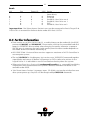
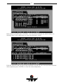
81,;7DUJHW,'DQG/81
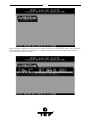
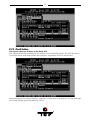
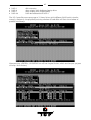
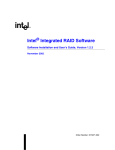
Target-IDs 0 and 1 with LUN 0 to 7 are reserved for "Direct Access Devices" (devices behaving like a hard disk or a removable hard and therefore configurable with GDTSETUP). There is a correlation between the Host Drive number GDTSETUP assigns (menu Configure Host
Drives), and the assigned target-ID and LUN:
Host-Drive Number = 8 * Target-ID + LUN
The Host Drive number is the number the drive is given in the list of available Host Drives
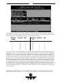
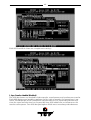
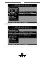
in the GDTSETUP program. The following exemplary screen shows a list of Host Drives. In
this example, there are two Host Drives installed.
Therefore, the first Host Drive has target-ID 0 / LUN 0 and the second target-ID 0 / LUN 1.
The formula for determining target ID and LUN from the existing Host Drive numbers yields
the following possible combinations for "Direct Access Devices":
+RVW'ULYH
QXPEHU
0
1
2
3
4
5
6
7
7DUJHW,'
/81
0
0
0
0
0
0
0
0
0
1
2
3
4
5
6
7
+RVW'ULYH
QXPEHU
8
9
10
11
12
13
14
15
7DUJHW,'
/81
1
1
1
1
1
1
1
1
0
1
2
3
4
5
6
7
This conversion is necessary because the single SCSI devices are not declared to the host
operating system in the order of their SCSI-IDs anymore, but according to the Host Drive
numbers they have in GDTSETUP. Host Drives are a prerequisite for the ICP Controller to
be able to link several SCSI devices to form a higher structure (i.e., RAID 5).
The sequence of the single Host Drives can be changed very easily by having GDTSETUP
sort them in its Configure Host Drives menu. In this way, it is also possible to change the boot
19
drive (it had previously been selected as boot drive because it has the lowest drive number,
that is, 0, and is therefore the first drive to be communicated to the system ).
Target ID and LUN of "Not Direct Access Devices" (devices such as streamers, tapes, CDROMS, etc., not configurable with GDTSETUP) are determined on the basis of the SCSI-ID
and the SCSI channel used by the ICP Controller. These devices can only be configured with
SCSI-IDs 2 to 6. SCSI-ID 0 and 1 are reserved for hard disks, SCSI-ID 7 for the ICP Controller.
If "Not Direct Access Devices" are configured on SCSI-ID 0 or 1, they are not recognized during the scanning process and can therefore not be used. The Target IDs of Not Direct Access
Devices are identical to their SCSI-ID, the LUN depends on the SCSI channel used (LUN 0 for
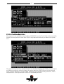
SCSI channel A and LUN 4 for SCSI channel B). Note: After a cold boot the GDT BIOS displays all connected devices with their physical coordinates, i. e. their SCSI-ID and SCSILUN, (see "Chapter B, ICP Controller Function Check").
6&6,,'RI1RW'LUHFW$FFHVV
'HYLFHV
2
3
4
5
6
8VHG*'7
6&6,FKDQQHO
A
A
A
A
A
81,;
7DUJHW,'
2
3
4
5
6
81,;
/81
0
0
0
0
0
2
3
4
5
6
B
B
B
B
B
2
3
4
5
6
4
4
4
4
4
Having to determine the Target ID and LUN in such a complicated manner might seem rather awkward. However, it is necessary to do so because the ICP Controllers have more than
one SCSI channel, whereas UNIX can only manage host adapters with one SCSI channel.
Therefore, the GDT UNIX driver has to make the appropriate transformations.
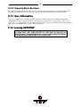
&RQILJXUDWLRQ([DPSOH
In the PCI computer are two ICP Controllers (HA 0 = 1st GDT, HA 1 = 2nd GDT), each with
two SCSI channels.
1 hard disk
as Host Drive no. 0 on HA0
1 hard disk
as Host Drive no. 0 on HA1
1 hard disk
as Host Drive no. 1 on HA1
1 Streamer
SCSI-ID 2, LUN 0 on SCSI channel A of HA0
1 CD-ROM
SCSI-ID 3, LUN 0 on SCSI channel A of HA0
1 DAT
SCSI-ID 2, LUN 0 on SCSI channel B of HA1
5HVXOW
HA
0
0
0
1
1
1
Target-ID
0
2
3
0
0
2
LUN
0
0
0
0
1
4
Device
1st hard disk, Host Drive no. 0 (boot- and
installation drive)
Streamer
CD-ROM
hard disk, Host Drive no. 0
hard disk, Host Drive no. 1
DAT
20
,,,QVWUXFWLRQVRQPNGHY$'0IRUY[2SHQ6HU
YHU
Whenever the program mkdev hd (ADM) is started, you will be asked for the coordinates of
the device you wish to install. The driver does not automatically display all devices connected, so after the installation you will find a tool named GDTSCAN in the directory '/etc'.
The scanning can take up to several seconds, especially when there is more than one controller in the system. The devices are displayed together with their host adapter number,
target-ID and LUN. These values are to be used in mkdev (ADM). Let's have a brief look at
how the HA-no., target-ID and LUN are determined. Please note that the UNIX driver always maps the first detected Host Drive with target-ID 0, LUN 0. Exactly this drive would be
used as a boot drive when the ICP Controller is to make the boot drive available. As an alternative for the following "new" mapping method of SCO UNIX V/386 3.2v5.x, you may also
use the mapping as described in section II.3 (for 3.2v2.0 & 3.2v4.x). To enable this ("old")
mapping, change in the
/etc/conf/pack.d/gdth/space.c
gdth_mapping=1
gdth_mapping=0
into
+RVWDGDSWHU1XPEHU+$
The host adapter number assigned to the ICP Controller is derived from the PCI slot number of the ICP Controller. Therefore, if there is only one ICP Controller installed in the PCI
bus computer system, the host adapter number=0. If there are two ICP Controllersinstalled,
the ICP Controller with the lower PCI Slot number is assigned host adapter number 0 and
the ICP Controller with the higher PCI slot number is assigned host adapter 1. (Note: After
a cold boot, the GDT BIOS displays a couple of messages, each beginning with the controller’s PCI slot number, e.g. "[PCI 0/3] 4 MB RAM detected". The number after the ‘/’ is the
slot number of the controller. This helps you to determine which is the order of the ICP
Controllers and and which host adapter number is assigned to them by UNIX. See also
chapter B, Hardware Installation).
81,;7DUJHW,'DQG/81
Target-IDs and LUNs for “Not Direct Access Devices“ (devices like streamers, tapes and
CD-ROMs and therefore not configurable via GDTSETUP), are directly assigned to the SCSIID and the channel of the ICP Controller. Host Drives are assigned in increasing order to
the free coordinates (bus number and target ID;LUN is always 0).
&RQILJXUDWLRQ([DPSOH
In the PCI computer are two ICP Controllers (HA 0 = 1st GDT, HA 1 = 2nd GDT), each with
two SCSI channels.
1 hard disk
as Host Drive no. 0 on HA0
1 hard disk
as Host Drive no. 0 on HA1
1 hard disk
as Host Drive no. 1 on HA1
1 Streamer
SCSI-ID 2, LUN 0 on SCSI channel A of HA0
1 CD-ROM
SCSI-ID 3, LUN 0 on SCSI channel B of HA0
1 DAT
SCSI-ID 2, LUN 0 on SCSI channel A of HA1
21
5HVXOW
HA
0
Bus
0
Target-ID
0
LUN
0
0
0
1
1
1
1
0
1
0
0
0
0
2
3
0
1
2
3
0
0
0
0
0
0
Device
1st hard disk, Host Drive no. 0
(boot drive)
Streamer
CD-ROM
hard disk, Host Drive no. 0
hard disk, Host Drive no. 1
DAT
hard disk, Host Drive no.2
Important Note: ‘Not Direct Access Devices’ must not be connected to Bus 0, Target-ID 0,
LUN 0. This is reserved for the boot device under SCO Unix 3.2V5.0
,,)XUWKHU,QIRUPDWLRQ
From version 4.x of SCO UNIX V/386 3.2, a media change can be made with the UNIX
commands MOUNT and UNMOUNT. Please make sure that the removable hard disk
keeps its GDTSETUP drive number when changing the media, otherwise a separate
ID/LUN entry is necessary for each single media (since the drive number depends on
the media and not the device containing it).
SCO UNIX V/386 3.2v4.x and later versions support a maximum of 4 ICP Controllers in
one computer system.
The tool GDTSYNC in the directory '/etc' carries out a UNIX SYNC command (update
super block) and causes all buffers still present in GDT's cache to be written to the
Logical Drives. It is advisable to use this tool before shutting down the system.
When using Direct Access Devices with exchangeable media (e.g., removable hard disks),
a media has to be inserted when the system is booted, otherwise the device is not
available under UNIX.
"Not Direct Access Devices" (streamer, tapes, CD-ROMs, etc) can be switched on even
after system power up, they will still be recognised by GDTSCAN afterwards.
22
23
&KDSWHU,,,
8VLQJ
J,,QWHUDFWLYH
H8
81,;
24
,,,8VLQJ,QWHUDFWLYH81,;
After having explained the installation of the GDT Host Drive in chapters B and C as well as
that of the Host Drives, we would now like to give you a few hints regarding the installation
of the operating systems
Interactive UNIX V/386 3.2v3 and 3.2v4.
For successful installation, it is essential to read the Interactive system manuals thoroughly. Besides the Interactive UNIX disks and documentation, the following GDT disks are
needed (they may be downloaded from our BBS or Website):
GDT Interactive UNIX 3.2v3&4 for sysadm
GDT Interactive UNIX 3.2v4 - for boot installation
(only for Interactive UNIX 3.2v4 and the boot installation)
,,,7UDQVSDUHQF\RI+RVW'ULYHV
The structure of the Host Drives, which have been installed with GDTSETUP (in chapter C),
is not known to UNIX. I.e., the operating system does not recognize that a given Host Drive
consists of a number of hard disks forming a disk array. To UNIX, this Host Drive simply
appears as one single hard disk with the capacity of the disk array. This complete transparency represents the easiest way to operate disk arrays under UNIX; neither UNIX nor the
PCI computer need to be involved in the administration of these complex disk array configurations.
,,,,QVWDOODWLRQDVDQDGGLWLRQDO&RQWUROOHU
Install the driver software with the help of sysadm, using the menu options Software, Install a
package. (The driver software for Interactive UNIX is on the GDT Interactive UNIX floppy
disk.). Now specify the drive containing the driver disk and select the floppy disk type
(720KB) (reading the floppy disk can take some time). During installation, a GDT driver corresponding to the IRQ used by the ICP Controller has to be selected. As discussed in chapter B of this user’s manual, the PCI System BIOS automatically assigns an IRQ to a PCI INT.
The IRQ used by a ICP Controller is displayed by the GDT BIOS after a cold boot.
After having successfully completed the installation of the GDT driver, you may introduce
another GDT Host Drive into the system by using kconfig and its menu options Configure,
HPDD, Reconfigure HPDD. In the next menu you enter the connected SCSI devices (type of
device, SCSI-ID and LUN). After this, link a new kernel in kconfig by using Build, Build a kernel,
then install with Install. At the next system reboot, the GDT displays a screen listing all its
connected devices. Connected tapes are instantly ready for use, they can be accessed immediately with programs such as mt for rewinding, deletion etc. Host Drives have to be
prepared with sysadm first, using the options Disk, Fixed Disk Management, Add a Fixed Disk to the
system (Partition Disk and Create UNIX Partitions), and mount to connect the file systems.
Please note that the hard disks must have been prepared (initialized) before with
GDTSETUP (the DOS configuration-program on the System Disk - DOS), and the Host
Drives must have been defined.
,,,,QVWDOODWLRQDV%RRW&RQWUROOHU
First initialize a hard disk connected to the ICP Controller (using GDTSETUP under DOS),
and install it as a Host Drive (see chapters C and I "Configure Host Drives"). The Host Drive
on which you wish to install the Interactive UNIX system must be assigned number 0
25
(GDTSETUP menu option Configure Host Drives). Now you can start the installation procedure. During installation, a GDT driver corresponding to the IRQ used by the ICP Controller
has to be selected. As discussed in chapter B of this user’s manual, the PCI System BIOS
automatically assigns an IRQ to a PCI INT. The IRQ used by a ICP Controller is displayed by
the GDT BIOS after a cold boot. After having successfully installed the basic Interactive system, use InstallPkg to install the software package OS File Management, kernel Configuration,
and afterwards the GDT driver software. After having installed other desired software, choose the menu option kconfig to configure the ICP Controller as boot controller and to enter
any other device connected to it. Then, a new kernel must be linked and installed (see above). After Exit and a system reboot, you can partition and mount Host Drives with sysadm
(see above). You can integrate the GDT driver into the kernel of the copy of the boot disks
in two different ways:
a) There is already a bootable system on another computer
In this case, the easiest method is to install the driver software for the ICP Controller on
this system and to link a kernel containing the ICP Controller as boot controller (see above). Then copy this kernel to the Interactive boot disk copy. This can be easily done since
this floppy disk contains a mountable file system. You can then start the installation with
this boot disk. Make sure that the controller's IRQ is set according to the entry in kconfig.
b) There is no bootable system available.
For Interactive UNIX 3.2v4, only.
When using this UNIX version, you have to use the GDT Interactive disk called GDT Interactive UNIX 3.2v4 - for boot installation. The installation is carried out according to the Interactive UNIX 3.2v4 documentation.
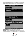
,,,81,;7DUJHW,'/81RID+RVW'ULYH1XPEHU
Target-IDs 0 and 1 with LUN 0 to 7 are reserved for "Direct Access Devices" (devices behaving like a hard disk or a removable hard disk and therefore configurable with GDTSETUP).
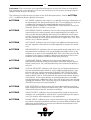
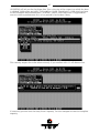
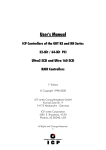
There is a fixed correlation between the Host Drive number in GDTSETUP (menu "Configure
Host Drives") and the target-ID and LUN. When a host-drive has been installed with
GDTSETUP, it has to be communicated to the UNIX system (in kconfig) by assigning a target-ID and LUN which are determined with the following formula:
Host-Drive Number = 8 * Target-ID + LUN
The host-drive number is the number the drive has in the list of available host drives in the
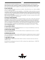
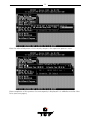
GDTSETUP program. The following exemplary screen shows a list of host drives in which
two host drives are installed.
26
Therefore, the first Host Drive has target-ID 0 / LUN 0 and the second target-ID 0 / LUN 1.
The formula for determining target ID and LUN from the existing host-drive numbers yields
the following possible combinations for "Direct Access Devices":
+RVW'ULYH
QXPEHU
0
1
2
3
4
5
6
7
7DUJHW,'
/81
0
0
0
0
0
0
0
0
0
1
2
3
4
5
6
7
+RVW'ULYH
1R
8
9
10
11
12
13
14
15
7DUJHW,'
/81
1
1
1
1
1
1
1
1
0
1
2
3
4
5
6
7
This conversion is necessary because the single SCSI devices are not declared to the host
operating system in the order of their SCSI-IDs, but according to the host-drive numbers of
GDTSETUP. The ICP Controller needs host-drives in order to be able to link several SCSI
devices to form a higher structure (i.e., RAID 5). The sequence of the single host-drives can
be changed very easily by having GDTSETUP sort them in its "Configure Host Drives" menu.
In this way, it is also possible to change the boot drive (it had previously been selected as
boot drive because it has the lowest drive number, that is, 0, and is therefore the first drive
to be communicated to the system ). There is one restriction that has to be observed with
Interactive UNIX: Even though gaps are allowed when numbering the host-drives, if there
are several Host Drives, a certain number for a device having a LUN greater than 0 may only
be selected if this number already exists for another device with LUN 0. In other words, a
certain number can only be assigned to a LUN >0 position if the LUN 0 position has also
been assigned.
Example: If a host-drive no. 13 exists (target-ID=1, LUN=5), there also has to be a hostdrive with number 8 (target-ID=1, LUN=0). Please keep this in mind when assigning the
27
numbers in GDTSETUP. Target ID and LUN of "Not Direct Access Devices" (devices such
as streamers, tapes, CD-ROMS, etc., not configurable with GDTSETUP) must be determined
on the basis of the SCSI-ID and the SCSI channel used by the ICP Controller. These devices
can only be configured with SCSI-IDs 2 to 6. SCSI-ID 0 and 1 are reserved for hard disks,
SCSI-ID 7 for the ICP Controller. If "Not Direct Access Devices" are configured on SCSI-ID 0
or 1, they are not recognized during the scanning process and can therefore not be used.
The Target IDs of Not Direct Access Devices are identical to their SCSI-IDs, the LUN depends on
the SCSI channel used (LUN 0 for SCSI channel A and LUN 4 for SCSI channel B). Note: After a cold boot, the GDT BIOS displays all connected devices with their physical coordinates, i.e., their SCSI-ID and SCSI-LUN, (see "Chapter B, ICP Controller Function Check").
6&6,,'RI1RW'LUHFW$FFHVV
'HYLFHV
2
3
4
5
6
8VHG*'7
6&6,FKDQQHO
A
A
A
A
A
81,;
7DUJHW,'
2
3
4
5
6
81,;
/81
0
0
0
0
0
2
3
4
5
6
B
B
B
B
B
2
3
4
5
6
4
4
4
4
4
Having to determine the Target ID and LUN in such a complicated manner might seem rather awkward. However, it is necessary to do so because the ICP Controllers have more than
one SCSI channel, whereas UNIX can only manage host adapters with one SCSI channel.
Therefore, the GDT UNIX driver has to make the appropriate transformations.
&RQILJXUDWLRQ([DPSOH
In the PCI computer are two ICP Controllers (HA 0 = 1st GDT, HA 1 = 2nd GDT), each having
two SCSI channels.
1 hard disk
as Host Drive no. 0 on HA0
1 hard disk
as Host Drive no. 0 on HA1
1 hard disk
as Host Drive no. 1 on HA1
1 Streamer
SCSI-ID 2, LUN 0 on SCSI channel A of HA0
1 CD-ROM
SCSI-ID 3, LUN 0 on SCSI channel A of HA0
1 DAT
SCSI-ID 2, LUN 0 on SCSI channel B of HA1
5HVXOW
HA
0
0
0
1
1
1
Target-ID
0
2
3
0
0
2
LUN
0
0
0
0
1
4
Device
1st hard disk, Host Drive no. 0 (boot- and
installation drive)
Streamer
CD-ROM
hard disk, Host Drive no. 0
hard disk, Host Drive no. 1
DAT
28
,,,)XUWKHU,QIRUPDWLRQ
During the installation of the GDT driver, additional tools are copied into the /etc directory. Before you can use them you have to create a special device file named
/dev/rgdth by means of "link"; this device file has to be placed on a device of a GDT
Host Drive.
For example, on ICP Controller 0 we have the Host Drive 1 which is HA 0, Target-ID 0,
LUN 1 under Interactive Unix. The corresponding special device file is
/dev/rdsk/c0t0dl1s0 (c0 = HA, t0 = Target-ID 0, d0 = LUN 0, s0 = Unix partition).
By means of "ln /dev/rdsk/c0t0d1s0 /dev/rgdth", the required special device file is generated.
A media change can be made with UNIX commands MOUNT and UNMOUNT. Please
make sure that the removable hard disk keeps its GDTSETUP drive number when
changing the media, otherwise a separate ID/LUN entry is necessary for each single
media (since the drive number depends on the media and not the device containing
it).
If you change the hardware configuration of your PCI computer system, it may happen
that the GDT is assigned to a different IRQ, as it was assigned during the installation
and operation of UNIX. In this case you need to run the installation again with a GDT
driver for the new IRQ, or change the hardware configuration so that the old IRQ is
available for the GDT again.
29
&KDSWHU,9
8VLQJ
J8
81,;:$5(
30
,98VLQJ8QL[:DUH
After having exposed the installation of the ICP Controller as well as that of the Host Drives
in chapters B and C, we would now like to give you some hints and pieces of advice on how
to install the operating system UnixWare version 2.x.
,97UDQVSDUHQF\RI+RVW'ULYHV
The structure of the Host Drives, which have been installed with GDTSETUP (in chapter C),
is not known to UNIX. I.e., the operating system does not recognize that a given Host Drive
consists of a number of hard disks forming a disk array. To UNIX, this Host Drive simply
appears as one single hard disk with the capacity of the disk array. This complete transparency represents the easiest way to operate disk arrays under UNIX; neither UNIX nor the
PCI computer need to be involved in the administration of these complex disk array configurations.
,9*HQHUDO,QVWDOODWLRQ1RWHV
In the following description, we shall explain the installation of UnixWare in connection
with the ICP Controller step by step. Apart from the UnixWare floppy disks, the CD-ROM
and the UnixWare documentation, you also need the GDT floppy disk:
UnixWare BTLD-Disk
In the following discussion, when we speak of a boot drive we refer to the drive which is first
integrated upon system power up. For the ICP Controller, this drive is the first Host Drive in
the list of GDT Host Drives, i. e. the Host Drive with number 0 (see GDTSETUP menu Configure Host-Drives). During the installation you will have to decide whether you want the ICP
Controller to make the boot drive available, or whether you want to operate the ICP Controller as an additional controller in the computer system. If the ICP Controller is the only
hard disk controller in the computer system, it will automatically make the boot drive available.
If there are more hard disk controllers, the controller which makes the first drive (the drive
containing the MS-DOS partition C:) available will be the boot controller. If the ICP Controller does not make the boot drive, you can skip the following paragraph.
,9*'7DV%RRW&RQWUROOHU
First initialize a hard disk connected to the ICP Controller (using GDTSETUP under DOS)
and install it as a Host Drive (see chapters C and M "Configure Host Drives"). If there are
several ICP Controllers in the system, this Host Drive must be connected to the first ICP
Controller found during a cold boot. In addition, the GDT BIOS must be enabled and the
SCSI-ID of the corresponding GDT SCSI channel must be set to 7.
Now you can begin the installation. Boot the system with the first UnixWare boot disk.
UnixWare scans the system for host adapters. When requested insert the GDT UnixWare
BTLD-Disk. The installation procedure which follows then has to be carried out as described
in the UnixWare documentation.
Important note: As already mentioned in chapter B “Hardware Installation”, the assignment
of an IRQ to an INT is made by the PCI System BIOS. The UnixWare versions 2.xy and higher
automatically recognize the IRQ of a PCI expansion card.
31
,9*'7DVDQDGGLWLRQDO&RQWUROOHU
We distinguish two cases.
a.) No ICP Controller has been configured for UnixWare yet.
In this case, the GDT driver must be installed from the GDT UnixWare BTLD-Disk by means
of the UnixWare desktop and the options "System Setup", "Application Setup". Alternatively, this procedure can be carried out from the UnixWare shell: "pkgadd -d /dev/dsk/f0t" (GDT
driver disk in drive 0).
b.) A ICP Controller has already been configured for UnixWare.
In this case, you only have to add an additional entry for the new ICP Controller. This is carried out by
/etc/scsi/pdiadd -d DRQ -v IRQ -m MEM gdth
for DRQ use 0 (not necessary for PCI boards), for IRQ write the IRQ number the ICP Controller uses. MEM corresponds with the DPMEM address of the ICP Controller (which is
displayed in the BIOS message of the ICP Controller after power up). In both cases, you
have to carry out a cold boot in order to use the new ICP Controller under UnixWare.
Example: /etc/scsi/pdiadd -d 0 -v 12 -m c8000 gdth.
After that, a reboot of the UnixWare system is necessary. No kernel link is required because
the driver will be dynamically loaded.
,9&RRUGLQDWHVRI6&6,GHYLFHV
D+RVWDGDSWHU1XPEHU+$
The host adapter number assigned to the ICP Controller is derived from the PCI slot number of the ICP Controller. Therefore, if there is only one ICP Controller installed in the PCI
bus computer system, the host adapter number=0. If there are two ICP Controllers installed, the ICP Controller with the lower PCI Slot number is assigned host adapter number 0
and the ICP Controller with the higher PCI slot number is assigned host adapter 1. (Note:
After a cold boot, the GDT BIOS displays a couple of messages, each beginning with the
controller’s PCI slot number, e.g. "[PCI 0/3] 4 MB RAM detected". The number after the ‘/’ is
the slot number of the controller. This helps you to determine which is the order of the ICP
Controllers and and which host adapter number is assigned to them by UNIX. See also
chapter B, Hardware Installation).
E8QL[:DUH%XVQXPEHU7DUJHW,'DQG/81
Target-IDs and LUNs for “Not Direct Access Devices“ (devices like streamers, tapes and
CD-ROMs and therefore not configurable via GDTSETUP), are directly assigned to the SCSIID and the channel of the ICP Controller. Host Drives are assigned in increasing order to
the free coordinates (bus number and target ID;LUN is always 0).
&RQILJXUDWLRQ([DPSOH
In the PCI computer are two ICP Controllers (HA 0 = 1st GDT, HA 1 = 2nd GDT), each with
two SCSI channels.
1 hard disk
as Host Drive no. 0 on HA0
1 hard disk
as Host Drive no. 0 on HA1
1 hard disk
as Host Drive no. 1 on HA1
1 Streamer
SCSI-ID 2, LUN 0 on SCSI channel A of HA0
1 CD-ROM
SCSI-ID 3, LUN 0 on SCSI channel B of HA0
1 DAT
SCSI-ID 2, LUN 0 on SCSI channel A of HA1
32
5HVXOW
HA
0
Bus
0
Target-ID
0
LUN
0
0
0
1
1
1
1
0
1
0
0
0
0
2
3
0
1
2
3
0
0
0
0
0
0
Device
1st hard disk, Host Drive no. 0
(boot drive)
Streamer
CD-ROM
hard disk, Host Drive no. 0
hard disk, Host Drive no. 1
DAT
hard disk, Host Drive no.2
,9)XUWKHU,QIRUPDWLRQ
During the installation of the GDT driver, additional tools are copied into the /etc directory. Before you can use them you have to create a special device file named /dev/rgdth
by means of "link"; this device file has to be placed on a device of a GDT Host Drive.
With ‘gdtsync’ from the /etc directory, you can determine the coordinates of a GDT Host
Drive. Usually the first Host Drive has the coordinates c0b0t0d0.
A special device file (character device) is ‘/dev/rdsk/c0b0t0d0s0. In this case, /dev/rgdth
can be generated with: ln /dev/rdsk/c0b0t0d0s0 /dev/rgdth.
(c0 = HA, b0 = Bus number, t0 = Target-ID 0, d0 = LUN 0, s0 = UnixWare partition).
All new SCSI devices will be automatically recognized and a corresponding specialdevice-file will be generated
Host Drives must be partitioned and a file system/file system(s) must be created. You
can do this with diskadd cCbBtTdD.
When using Direct Access Devices with exchangeable media (e.g., removable hard disks)
that are not reserved for the raw service, a media has to be inserted either when the
system is booted, or with GDTSETUP (mount/unmount), otherwise the device is not
available under UnixWare.
The GDT UnixWare driver supports Direct Access Devices (e.g., hard disks, removable hard-
disks) as SCSI-raw devices. This is especially important if you use removable hard disks
which you want to exchange with other controllers. How to reserve a device for the
SCSI-raw service is described in the file space.c on the GDT BTLD disk (example and
documentation).
Multi-processor support: The GDT device drivers for UnixWare 2.01 and UnixWare 2.1
support multi-processor systems.
33
&KDSWHU9
*'76(783
3LLQ
Q'
'HWDLO
34
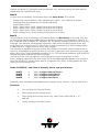
9*'76(783LQ'HWDLO
We refer to firmware as the operating system which controls the ICP Controller with all its
functions and capabilities. The firmware exclusively runs on the ICP Controller and is stored in the Flash-RAM on the ICP Controller PCB. The controlling function is entirely independent of the PCI computer and the host operating system installed (for example UNIX),
and does not "drain" any computing power or time from the PCI computer. According to the
performance requirements needed, the ICP Controllers are available with two firmware variants. The firmware is either already installed on the controller upon delivery, or can be
added as an upgrade: RAIDYNE upgrade.
Standard Firmware (installed on the GDT61x8RD controllers).
In addition to simple controlling functions regarding SCSI hard disks or removable
hard disks, this version allows disk chaining (several drives can be linked in order
to form a single "large" drive), and the configuration of Array Drives of the types
data striping (RAID 0) and disk mirroring or duplexing (RAID 1).
RAIDYNE Firmware (installed on the GDT65x8RD controllers). In addition to disk
chaining, RAID 0 and RAID 1, RAIDYNE allows you to install and control Array
Drives of the types RAID 4 (data striping with dedicated parity drive), RAID 5 (data
striping with distributed parity) and RAID10 (a combination between RAID 0 and 1)
RAIDYNE is the name of the ICP disk-array operating system for the ICP Controllers. Unlike
pure software solutions, RAIDYNE is totally independent of the host operating system, and
can therefore be accessed under MS-DOS, Windows, OS/2, SCO-UNIX, Interactive UNIX,
Novell NetWare, etc.. Special RAID drivers are not needed. The integration of a RAID Array
Drive into the host operating system is carried out with the same drivers used for the integration of a single SCSI hard disk. All ICP Controllers are equipped with a hardware which
is particularly well suited for Array Drives. RAIDYNE uses this hardware with extreme efficiency and therefore allows you to configure Array Drives that do not load the host computer (whereas all software-based RAID solutions more or less reduce the overall performance
of the host computer.).
97KHIRXU/HYHOVRI+LHUDUFK\LQWKH*'7)LUPZDUH
Both GDT firmware versions (Standard and RAIDYNE) are based on four fundamental levels
of hierarchy. Each level has its "own drives" ( = components). The basic rule is:
To build up a “drive“ on a given level of hierarchy, the “drives“ of the next lower level
of hierarchy are used as components.
/HYHO
Physical Drives = hard disks, removable hard disks, some MO drives are located on the
lowest level. This can be either devices with a SCSI interface, or devices with a Fibre Channel Arbitrated Loop (FCAL) port.
They are the basic components of all "drive constructions" you can set up. However, before
they can be used by the firmware, these hard disks must be "prepared", a procedure we call
initialization. During this initialization each hard disk receives information which allows a
univocal identification even if the SCSI-ID, FCAL-ID or the controller is changed. For
reasons of data coherency, this information is extremely important for any drive construction consisting of more than one physical drive.
/HYHO
On the next higher level are the Logical Drives. Logical Drives are introduced to obtain full
independence of the physical coordinates of a physical device. This is necessary to easily
35
change the whole ICP Controller and the channels, IDs, without loosing the data and the
information on a specific disk array.
/HYHO
On this level of hierarchy, the firmware forms the Array Drives. This can be:
Single Disks (one hard disk, some vendors call it JBOD - Just A Bunch Of Drives)
Chaining Sets (concatenation of several hard disks)
RAID 0 Array Drives
RAID 1 Array Drives, RAID 1 Array Drives plus hot fix drive
RAID 4 Array Drives, RAID 4 Array Drives plus hot fix drive
RAID 5 Array Drives, RAID 5 Array Drives plus hot fix drive
RAID 10 Array Drives, RAID 10 Array Drives plus hot fix drive
/HYHO
On the highest level of hierarchy, the firmware forms the Host Drives. In the end, only these Host Drives can be accessed by the host operating system of the computer. Drives C, D,
etc. under MS-DOS, Windows NT, NetWare, etc. are always referred to as Host Drives by the
firmware. The firmware automatically transforms each newly installed Logical Drive and
Array Drive into a Host Drive. This Host Drive is then assigned a Host Drive number which
is identical to its Logical Drive or Array Drive number.
The firmware is capable of running several Host Drives of the most various kinds at the same time. An example for MS-DOS: drive C is a RAID 5 type Host Drive (consisting of 5 hard
disks), drive D is a single hard disk, and drive E is a CD-ROM communicating with RAIDYNE
through corelSCSI and the GDT ASPI manager.
On this level the user may split an existing Array Drive into several Host Drives.
After a capacity expansion of a given Array Drive the added capacity appears as a new Host
Drive on this level. It can be either used as a separate Host Drive, or merged with the first
Host Drive of the Array Drive.
Within GDTSETUP, each level of hierarchy has its own special menu:
/HYHO
/HYHO
/HYHO
/HYHO
Ö
Ö
Ö
Ö
Menu: Configure Physical Devices
Menu: Configure Logical Drives
Menu: Configure Array Drives
Menu: Configure Host Drives
Generally, each installation procedure passes through these 4 menus, starting with level 1.
Therefore:
First initialize the Physical Drives.
Then configure the Logical Drives.
Then configure the Array Drives (e.g. Array Drives with RAID 0, 1, 4, 5
and 10).
Finally, configure the Host Drives.
36
9+RVW'ULYH7\SHVLQ5$,'<1(
The following summary gives you an overview of all Host Drive types you can create with
the GDT firmware. The ICP Controller can simultaneously control several Host Drives of
most various types.
For instance, MS-DOS drive C could be a Host Drive of the type disk (consisting of a single
hard disk), MS-DOS drive D is a type RAID 5 Array Drive, MS-DOS drive E is a Host Drive of
the type chain, and MS-DOS drive F is a CD-ROM which communicates with MS-DOS
through corelSCSI and the GDT ASPI manager.
$YDLODEOHZLWK
)LUPZDUHYDULDQW
7\SHRI+RVW
'ULYH
'HVFULSWLRQRI+RVW'ULYH
,QVWDOODWLRQ
RQ/HYHO
65
'LVN
65
&KDLQ
65
65
5
0LUURU5$,'
5$,'
5$,'
5
5$,'
5
5$,'
DVVLJQPHQW+RVW'ULYHWR
6&6,GHYLFH
&RQFDWHQDWLRQRIVHYHUDO6&6,
GHYLFHV
0LUURULQJRI/RJLFDO'ULYHV
'DWD6WULSLQJ
'DWD6WULSLQJZLWKSDULW\
GULYH
'DWD6WULSLQJZLWKVWULSHG
SDULW\
&RPELQHG5$,'DQG
0LQLPXP
QXPEHURI
6&6,GHYLFHV
S = Standard; R = RAIDYNE Firmware.
96&6,'HYLFHV:KLFKFDQEH&RQILJXUHG:LWK*'76(783
SCSI devices which can be configured with GDTSETUP are called Direct Access Devices (SCSI
devices such as hard disks or removable hard disks, or other devices behaving like a hard
disk). SCSI devices other than SCSI hard disks or removable hard disks, or devices that do
not behave like them, are called Not Direct Access Devices. They are not configured with
GDTSETUP and cannot form Host Drives. These SCSI devices are either run through the
ASPI interface (Advanced SCSI Programming Interface) (MS-DOS, Windows, Novell NetWare or OS/2), or they are directly accessed from the operating system (true for UNIX and
Windows NT). For details on how to operate these devices, please refer to the corresponding chapters of this manual.
9/RDGLQJ*'76(783
Any installation or maintenance procedures regarding the ICP Controller are carried out
with the configuration program GDTSETUP. The monitoring program GDTMON allows
continuous monitoring and maintenance of the ICP Controller and the connected Array
Drives. The GDTMON utility also include options to replace a defective drive with a new
one (Hot Plug) and is available for most of the operating systems supported by the ICP
Controllers. GDTSETUP allows you to set up single disks or complex Array Drives with
simple and user-friendly installation procedures. Little previous knowledge is needed to be
able to use GDTSETUP efficiently. It is only necessary to understand the hierarchy levels in
the ICP Controller firmware. For the user's convenience the GDTSETUP program is available
in two different variants:
37
GDTSETUP loaded from the ICP Controller's Flash-RAM after switching on the computer
GDTSETUP loaded from disk under MS-DOS.
The header of the GDTSETUP program indicates with a letter after the version number,
whether GDTSETUP was loaded from disk or from Flash-RAM:
"R" for GDTSETUP loaded from the Flash-RAM after switching on the computer
"D" for GDTSETUP loaded from Disk, i.e., under MS-DOS.
Loading GDTSETUP with <CTRL><G> from the Flash-RAM is very comfortable since no
operating system is required to carry out the configuration and setup works.
On the other side, loading GDTSETUP from disk (i.e., under MS-DOS) becomes necessary
for tasks like partitioning or enabling a totally disabled GDT BIOS (which includes
GDTSETUP).
96SHFLDO.H\VLQ*'76(783
&XUVRUNH\V n DQG p
Used to select a menu option or command.
(17(5!NH\
Confirms a choice, entry, warning or message in GDTSETUP.
(6&!NH\
Exits the current menu.
63$&(!EDU
Multiple selections, or toggling between a number of preset options.
)XQFWLRQNH\)!
This key has different functions, depending on the menu you are in:
a.
b.
Toggle between Express or Enhanced Setup.
Display drive configuration.
)XQFWLRQNH\)!
To Lock and Unlock removable media.
)XQFWLRQNH\)!
Refresh Information.
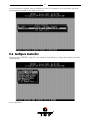
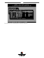
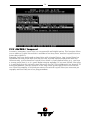
When GDTSETUP is loaded, the main menu appears as shown below:
9([SUHVV6HWXS
This function allows the easy setup of Array Drives and does not require any previous
knowledge. If you choose this function, GDTSETUP carries out the complete installation
entirely on its own, giving you, for example, a fully operational RAID 5 Array Drive with optimized settings (for instance, with all SCSI features of a given hard disk activated).
38
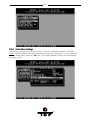
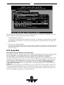
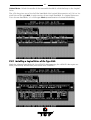
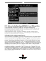
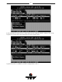
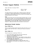
After selecting Configure Host Drives and Create new Host Drive, GDTSETUP scans the system for
ICP Controllers and "free" hard disks (i.e., drives which are not yet logical drives or Host
Drives or part of Array Drives).
39
Select with the <Space> bar the hard disks you want to integrate into the new Host Drive.
Depending on the number of selected drives in the Choose Type windows all possible Host
Drive configurations are high-lighted.
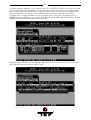
Press <ENTER> . You may select the desired Host Drive type. In our example select RAID5
and press <ENTER> .
40
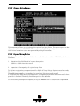
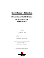
That's it!
As you can see from the next picture, the RAID5 Array Drive has been fully automatically
configured. It is in the build state.
Press several times <F2> to get detailed information on the Array Drive's configuration and
components.
41
Press several times <ESC> to leave GDTSETUP. A new screen comes up giving you detailed
progress information on the build process.
As you can see, there are already 6% of the build process completed.
If you press <ESC> GDTSETUP warns you that the array is not yet redundant.
42
Pressing again <ESC> brings up the following screen, telling you the system needs a reboot
to recognize the new Host Drive(s).
96HOHFW&RQWUROOHU
If there are more GDT RD Series controllers in the PCI computer, Select Controller lets you
select the controller where you can apply all of the following GDTSETUP choices to. The
currently selected controller is displayed on the lower left side of the screen. Below "Position", the PCI Slot number is displayed. The available features of the ICP Controller depend
43
on the firmware installed. After a cold boot of the PCI computer, the controllers are recognized and initialized in the order of this list.
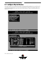
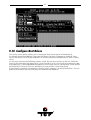
9&RQILJXUH&RQWUROOHU
After pressing <ENTER> and <F2> the Advanced Setup allows to select the Configure Controller
menu option.
Press <ENTER> .
44
9&RQWUROOHU6HWWLQJV
(To change a setting, move the cursor keys n and p to the field and press <ENTER> .
Note: In order to obtain the full performance of your ICP Controller, it is very important
that the Delayed Write function is 2Q, too. If you find a different setting, we recommend
changing it now.
45
Function
(*)
Cache On
(*)
Delayed Write On
BIOS
BIOS Warning Level
Supported BIOS drives
Memory Test
SCSI-ID
SCSI Termination
(*)
Possible Settings
On, Off
On, Off
Enabled, Disabled
All messages, Fatal errors
2, 7
No Test, Standard, Double Scan, Intensive
0,1,2,3,4,5,6,7
On, Off, Auto
Factory Setting
On
On
Enabled
Fatal errors
2
Standard
7
On
Can also be changed with the GDTMON online utility.
9)LUPZDUH8SGDWH
The firmware, the BIOS and the GDTSETUP program of the ICP Controller are stored in a
Flash-RAM which is part of the ICP Controller hardware. In contrast to EPROMs, FlashRAMs can be re-programmed many times and without the complicated UV-light erasing
procedure. Thus, both software modules can be easily updated without having to remove
the controller from its PCI slot. Firmware and BIOS are part of the *'7B53): file. The file
has an extension (e.g. GDT_RPFW.009) which indicates the version stepping. The latest version of the this file can be downloaded either from our 24h BBS (+49-(0)-7131-5972-15) or
from our Website http://www.icp-vortex.com. We recommend that you also download the
packed files which contain the latest programs/drivers for the operating system used on
your system. Observe the following order when carrying out the updating procedure:
1. Get the latest GDT_RPFW file for the ICP Controller (download it from our BBS, or our
Website, or ask for an upgrade disk if you do not have a modem). The file does NOT
need to be expanded !
2. Format a 3.5" HD disk (1.44MB) and copy the GDT_RPFW file on this disk.
3. After loading GDTSETUP (from Flash-RAM or from disk under MS-DOS) select the desired ICP Controller for the firmware update and press the <F2>-key to enter the Advanced Setup.
4. Select Configure Controller and thereafter Firmware Update. Insert the disk with the firmware
file into drive A. GDTSETUP loaded from the Flash-RAM will display a list of the valid
files found on the disk. If you have loaded GDTSETUP from disk you have to enter the
path "A:", first.
46
The update process starts as soon as the desired GDT_RPFW file has been selected. Strictly
observe the messages and instructions of GDTSETUP. It is extremely important that the
system is not switched off or reset during the update process. It is very likely that this
would cause the ICP Controller to become inoperable.
The new versions of the GDT Firmware, the BIOS and GDTSETUP are available after the next
cold-boot.
47
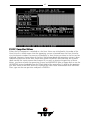
9&RQILJXUH3K\VLFDO'HYLFHV
This menu allows you to prepare hard disks and removable hard disks for use with the ICP
Controller (hierarchy level 1). You can scan the SCSI bus and the FCAL port(s) again for a
given ID (this may become necessary when another device is being connected during the
operating session).
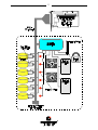
This screen tells you:
48
- the SCSI channel (SCSI) or FCAL port (FCAL)
- which a drive has (the entry I/O processor stands for the according I/O channel of the
ICP Controller. Its default setting is ID 7 for SCSI and ID 125 for FCAL.
- the state of initialization ("i" = initialized)
- the names of the drives
- the state, [RW] = Read + Write, [RO] = Read only, [RM] = Removable
- the gross capacity
- if component of a Logical Drive
Use the cursor keys n and p to highlight the drive you wish to initialize. When a hard disk is
selected with <ENTER>, a new screen is displayed.
You may select the high-lighted menu options. The other options are either not appropriate to the type of device (removable hard disk), or currently blocked because of security
reasons (e.g., the drive belongs to an Array Drive)
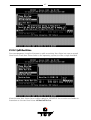
96&6,3DUDPHWHU,QLWLDOL]H
This option can destroy all data on the hard disk.
If a hard disk is not yet initialized, you have to initialize it first. GDTSETUP copies ICP specific configuration blocks on the hard disk, a primary block and a mirrored secondary block.
The possible settings are different if you select a SCSI hard disk or a Fibre Channel hard
disk.
With a FCAL hard disk there are only a few settings which are relevant. You should always
check that they are all "Enabled" or "On".
49
With SCSI hard disks there are a couple more settings:
6\QF7UDQVIHU(QDEOHG'LVDEOHG
The SCSI-bus knows two methods of data transfer: asynchronous and synchronous transfer.
Each SCSI device must be able to perform the first type of transfer, the second one is optional. The advantage of the synchronous transfer consists in a higher data transfer rate,
since the signal transfer times on the possibly long SCSI-cable have no influence on the
transfer rate anymore. Two SCSI-bus participants which want to exchange data between
50
each other have to check if and how (i.e., with which parameters) a synchronous data
transfer between them is possible. Therefore, the mere setting does not automatically enable synchronous data transfer; this mode is only effective if both devices support it and
after they have checked their capability of communicating with each other in this mode.
6\QF7UDQVIHU5DWH
This is the synchronous data transfer rate in MB/se. Ultra SCSI allows on a 8 Bit bus 20MB/s
and on a 16 bit bus 40MB/s.
If a given SCSI-cable does not allow 10.0 MB/s ( = FAST-SCSI), the data transfer rate can be
reduced to a value that allows a trouble-free data transfer. The reason for such a restriction
is not necessarily a "bad" SCSI-cable. Lowering the transfer rate may also become necessary when you set up a special configuration with a very long SCSI-cable whose length simply
does not allow 10.0 MB/s.
Even if you set the maximum speed to 10, 20 or 40 MB/s, this does not mean that the SCSI
device actually supports this transfer rate.
'LVFRQQHFW(QDEOHG'LVDEOHG
The concept of the SCSI-bus allows several participants (8 IDs with 8 LUNs each). All these
participants ought to be able to use the bus in a manner that causes the least reciprocal
disturbance or obstruction. A participant should therefore vacate the bus if he does not
need it. For reasons of performance, it is particularly important to guarantee a high degree
of action overlapping on the SCSI-bus. This high degree of overlapping becomes possible
when a SCSI device is enabled to be disconnected, thus leaving the bus to be used by
another participant. If there is only one SCSI device connected to the SCSI-bus, "Disconnect" should be disabled.
3URWRFRO6&6,,,6&6,,,,
If a drive supports a particular SCSI specification (II, or III) you should always use the highest protocol level the drive supports.
'LVN5HDG&DFKH2Q2II
This is the read ahead cache of the hard disk. Because of performance reasons it should
always be enabled (On).
'LVN:ULWH&DFKH2Q2II
This is the delayed write cache of the hard disk. Because of performance reasons it should
always be enabled (On), except during the installation of operating systems like Windows
95 and Windows NT.
7DJJHG4XHXHV2Q2II
Tagged Queues is a SCSI feature which allows the drive to execute more than one command at a time.
If you leave this configuration form with <ESC> and you have made changes , GDTSETUP
displays a security request.
51
The warning of the destruction of all data implies different evaluations, depending on the
device's current state and the options you selected:
1. First Initialization of the Device
In this case, the warning must be taken seriously. If the drive was previously connected
to a different controller (e.g. NCR etc.) and still contains important data, this data will
be lost now.
2. The Device was already initialized
If only internal parameters such as Disconnect, Synchronous Transfer, and SCSI Options
have been changed, the data on the drive remains intact. Only the function state of the
device changes.
9)RUPDW'LVN
This option destroys all data on the hard disk.
All manufacturers of hard disks deliver their products already formatted and surface-tested.
For new hard disks it is neither necessary, nor advisable to perform the Format Disk.
This procedure is only indicated if you have doubts on the hard disk's condition.
The time required for the Format Disk of a hard disk depends on the hard disk itself. It can
take quite a long time (up to days !). Often it seems that nothing happens and that the system hangs (no LED indication). If you put your ear on the hard disk you can hear the actuator stepping (with some drives one step per minute or longer). Never interrupt a
Format Disk procedure. This may lead with a very high probability to a non-functioning
hard disk.
Before the actual formatting, GDTSETUP asks you whether the "Grown Defect" table of the
hard disk should be deleted. Some users believe that this makes a hard disk with a lot of
grown defects like new. This is wrong. As soon as the bad sectors are accessed again, a reassign will happen, generating a new grown defect.
52
9&KHFN6XUIDFH
This option destroys all data on the hard disk.
This option allows the checking of the surfaces of the hard disk media. The GDT RD Series
Controller writes and reads certain data patterns and checks them for correctness.
After confirming the security request, a progress information is displayed. You can interrupt
the Check Surface option by pressing <ESC>.
53
99LHZ'HIHFWV6WDWXV
This option allows you to check the number of media defects the selected hard disk has.
Grown defects. Number of media defects that have occurred in addition to the media defects the hard disk already had upon delivery.
Primary defects. Number of media defects that the hard disk already had upon delivery.
54
Last status: The Last Status gives detailed information on the last failure of a hard disk.
The information is only present until the next hard reset of the system and may help for
deeper failure analysis or tracing.
The following listed messages are part of the SCSI documentation. Format: [""""\]
(???? = additional device specific messages)
[""""K
NO SENSE. Indicates that there is no specific sense key information to
be reported for the designated logical unit. This would be the case for
a successful command or a command that received CHECK
CONDITION or COMMAND TERMINATED status because one of the
filemark, EOM, or ILI bits is set to one.
[""""K
RECOVERED ERROR. Indicates that the last command completed
successfully with some recovery action performed by the target. Details may be determinable by examining the additional sense bytes
and the information field. When multiple recovered errors occur during one command, the choice of which error to report (first, last, most
severe, etc.) is device specific.
[""""K
NOT READY. Indicates that the logical unit addressed cannot be accessed. Operator intervention may be required to correct this condition.
[""""K
MEDIUM ERROR. Indicates that the command terminated with a non
recovered error condition that was probably caused by a flaw in the
medium or an error in the recorded data. This sense key may also be
returned if the target is unable to distinguish between a flaw in the
medium and a specific hardware failure (sense key 4h).
[""""K
HARDWARE ERROR. Indicates that the target detected a nonrecoverable hardware failure (for example, controller failure, device
failure, parity error, etc.) while performing the command or during a
self test.
[""""K
ILLEGAL REQUEST. Indicates that there was an illegal parameter in
the command descriptor block or in the additional parameters supplied as data for some commands (FORMAT UNIT, SEARCH DATA,
etc.). If the target detects an invalid parameter in the command descriptor block, then it shall terminate the command without altering
the medium. If the target detects an invalid parameter in the additional parameters supplied as data, then the target may have already
altered the medium. This sense key may also indicate that an invalid
IDENTIFY message was received (6.6.7).
[""""K
UNIT ATTENTION. Indicates that the removable medium may have
been changed or the target has been reset. See 7.9 for more detailed
information about the unit attention condition.
[""""K
DATA PROTECT. Indicates that a command that reads or writes the
medium was attempted on a block that is protected from this operation. The read or write operation is not performed.
[""""K
BLANK CHECK. Indicates that a write-once device or a sequential access device encountered blank medium or format-defined end-of-data
indication while reading or a write-once device encountered a nonblank medium while writing.
55
[""""K
VENDOR-SPECIFIC. This sense key is available for reporting vendor
specific conditions.
[""""$K
COPY ABORTED. Indicates a COPY, COMPARE, or COPY AND VERIFY
command was aborted due to an error condition on the source device,
the destination device, or both. (See 8.2.3.2 for additional information
on this sense key.)
[""""%K
ABORTED COMMAND. Indicates that the target aborted the command. The initiator may be able to recover by trying the command
again.
[""""&K
EQUAL. Indicates a SEARCH DATA command has satisfied an equal
comparison.
[""""'K
VOLUME OVERFLOW. Indicates that a buffered peripheral device has
reached the end-of-partition and data may remain in the buffer that
has not been written to the medium. A RECOVER BUFFERED DATA
command(s) may be issued to read the unwritten data from the buffer.
[""""(K
MISCOMPARE. Indicates that the source data did not match the data
read from the medium.
["""")K
RESERVED.
9'HLQLWLDOL]H'LVN
This menu option allows you to de-initialize a hard disk which has previously been initialized for use with the ICP Controller. By doing so, the specific GDT information present on
the device is removed. Obviously, the de-initialization cannot restore data that was lost
during initialization.
9/RFN8QORFN'LVN
This option is only high-lighted when you have selected a removable hard disk (e.g.,
Syquest, Iomega). Before you can initialize a cartridge you have to lock it. Before removing
it you have to unlock it.
9&RQILJXUDWLRQRI6$)7(6XEV\VWHPV
Before you can use the Auto Hot Plug with a SAF-TE subsystem, you first have to configure
the subsystem (more precisely it's intelligence, the so-called SEP - SAF-TE Enclosure
Processor).
In the following list of devices, the entry "ESG-SHV..." represents the SEP of the connected
SAF-TE subsystem. With the GDT6519RD and GDT6529RD SAF-TE is only supported on the
Ultra Wide SCSI channel.
56
The next page shows a block diagram of a SAF-TE subsystem.
57
58
After selecting the SEP press <ENTER> . You can either configure the SAF-TE Slots (i.e.,
the drive bays in the subsystem), or view the enclosure's status.
With the <SPACE>-bar you can assign hard disks to a SAF-TE slot. Once you have finished
the assignment press <ENTER> to save the new configuration.
59
In this example 1 of the 5 available slots in the subsystem is occupied with a hard disk.
The following screen shows you the enclosure's status. Features which are marked with
(Not available) are not implemented in the subsystem/SEP.
9&RQILJXUH/RJLFDO'ULYHV
Logical Drives (hierarchy level 2) are installed in this main menu option.
Selecting Configure Logical Drives leads you to the screen shown next. As you can see, there is
already one Logical Drive in the list. The drive's name has been assigned automatically and
60
contains the channel description and the ID after the underscore ("_"). This can serve as a
reminder when you install a complex system with many drives (naturally you can change
the name). After having selected a Logical Drive, you can carry out various operations.
Change Drive Name. Here you can enter a name for the selected drive.
Remove Drive. This menu option lets you remove a single Logical Drive from the list of
available Logical Drives. (Note: Logical Drives belonging to a RAID 0, 1, 4, 5 or 10 Host
Drive cannot be removed. To do so, the corresponding Host Drive has to be removed first.)
61
Unload Drive. Unlock the media of the removable hard disk, which belongs to the Logical
Drive.
The <F2>-key gives you a list of all the hard disks this Logical Drive consists of. If it is a Logical Drive of the type Disk, it only consists of one single hard disk. If a Logical Drive consists of more hard disks, it is of the type Chain (concatenation of several hard disks).
9,QVWDOOLQJD/RJLFDO'ULYHRIWKH7\SH'LVN
Mark the selected hard disk with the <SPACE>-bar (pressing the <SPACE>-bar again undoes your choice) and confirm your choice with <ENTER>.
62
A security request appears. If you confirm with <Y>, GDTSETUP allows you to limit the size
of the Logical Drive. This becomes interesting when you configure later on an Array Drive
with several identical Logical Drives and you want to make sure that you get appropriate
spare hard disks in the future. It would be bad luck if the new hard disk would have
8530MB, only. It simply wouldn't fit into the Array Drive. If you limit the capacity to e.g.,
8500MB from the beginning, you can be sure that all future 9GB hard disk will have at least
8500MB and thus can be used as spare hard disk.
After pressing <ENTER> the list appears again, but with a new entry. The <F2>-key shows
the hard disk forming the new Logical Drive.
63
9,QVWDOOLQJD/RJLFDO'ULYHRIWKH7\SH&KDLQ
In some literature Disk Chaining is also called Disk Spanning. You can picture the functioning mechanism of a type Chain Logical Drive as follows: all hard disks forming the Logical
Drive are linked together one by one in the exact same order in which they have been selected with the <SPACE>-bar. This concatenation can be compared with a chain. If, for example, the Logical Drive consists of 4 hard disks with 2000MB each, the Logical Drive will
have a capacity of 8000MB. When data is written to this Logical Drive, the first hard disk is
filled first, then the second, and so on.
Although it is not advisable, Logical Drives of the type Chain, can also be components of
Array Drives.
Select the hard disks with the <SPACE>-bar and then confirm with <ENTER>.
A security request appears. If you confirm with <Y >, GDTSETUP allows you to limit the size
of the Logical Drive. This becomes interesting when you configure later on an Array Drive
with several identical Logical Drives and you want to make sure that you get appropriate
spare hard disks in the future. If you limit from the beginning the capacity to e.g., 8500MB,
you can be sure that all future 9GB hard disk will have at least this capacity and thus can be
used as spare hard disk.
64
After pressing <ENTER> the list appears again, but with a new entry. The <F2>-key shows
the hard disk forming the new Logical Drive.
9&RQILJXUH$UUD\'ULYHV
This main menu option allows you to configure Array Drives (level of hierarchy 3).
Array Drives with the following listed RAID levels can be configured within this menu.
RAID 0
pure data striping without redundancy
65
RAID 1
RAID 4
RAID 5
RAID 10
disk mirroring
data striping with dedicated parity drive
data striping with striped parity
RAID 0 combined with RAID 1
The ICP Controller can manage up to 35 Array Drives (with different RAID levels) simultaneously. Obviously, the physically existing number of hard disks will limit the number of
parallel used Arrays.
After pressing <ENTER>, GDTSETUP lists all free Logical Drives, which are free (not yet part
of Array / Host Drives).
66
Move the selection-bar to the second entry and select Logical Drives No. 1, 3 and 4.
The "M" means Master. For a striping array (RAID 0, 4, 5, 10), this is the first Logical Drive in
the array. For a RAID 1 (mirroring) array this is the Logical Drive which contains the valid
data and which should be copied to the second Logical Drive. After pressing <ENTER>
GDTSETUP displays a list of possible RAID levels. The number of previously selected Logical Drives determines the high-lighted levels. In our case RAID 10 is not selectable, since it
requires at least 4 Logical Drives.
For this example we select RAID-5 and press <ENTER> .
67
GDTSETUP will ask you for the Stripe Size. This is the size of the stripes into which the data
is divided. Valid values are 16KB, 32KB, 64KB or 128KB. The default is 32KB which we leave
for this example and therefore press <ENTER>. (Note: 32KB stripe size is suggested because in various performance tests it has proved to be the best value.).
This security request has to be taken seriously. If you confirm with <Y> all data are lost.
If necessary you can limit the Array Drive's capacity. For this example we take the complete
capacity.
68
The Array Drive has entered the build state, i.e., the parity information is currently generated.
After completion of the build process, the Array Drive's state is ready, i.e., fault tolerant.
If you select the new Array Drive, you are offered various menu option:
69
91RWHVRQWKH&RQILJXUDWLRQRI5$,'DQG$UUD\V'ULYHV
(1) Use preferably Logical Drives of the type disk to build an Array Drive.
Of course, RAID Array Drives can be configured with Logical Drives of the type chain, too,
but the aspects of security should be taken into consideration as well. For regular RAID
Array Drives, type disk Logical Drives are used.
(2) The Logical Drives of an Array Drive should have the same storage capacity.
In order not to waste valuable storage capacity, you should only use Logical Drives that
have the same storage capacity for an Array Drive.
(3) The Hot Fix drive provides the utmost security.
One of the reasons for which RAID Array Drives are used definitely lies with the redundancy
they provide, that is, the data security you still have even in the event of a hard disk failure,
thus resting assured against loss of data and time. For the purpose of the following considerations, we define the term time without redundancy, TWR. Set apart the time needed to
set up the Array Drive (state build), the time without redundancy should be kept as short as
possible. Let us assume that one of the hard disks of a RAID 5 Array Drive fails. The Array
Drive is without redundancy. TWR starts to run. Any superfluous prolongation of the TWR
(because you have to get a replacement hard disk, or because you did not realize the failure
immediately since you didn't hear the ICP Controller's alarm signal, or because nobody
checked the file server) increases the risk of data loss which will occur if a second hard disk
should fail. Therefore, new redundancy should be created as soon as possible and in an
entirely automated manner. Integrating a Hot Fix drive as an immediately available and
auto-replacing hard disk is the only way to keep the TWR as short as possible. Only a Hot
Fix drive can ensure optimal Array Drive security and constant data availability. Of course a
Hot Fix drive is not mandatory. If you control the Array Drive at regular intervals and immediately replace a defective hard disk (by shutting down the system or Hot Plug), you can do
without a Hot Fix drive.
70
(4) States of a RAIDYNE Array Drive
An Array Drive under the RAIDYNE operation system can assume seven different operational modes. An Array Drive is fully operational when in the ready state. All redundant information is present, that is, a hard disk can fail without impairing the functionality of the
Array Drive. This is the normal state of an Array Drive.
idle
ready
fail
build
rebuild
expand
error
Idle state. This mode is characterized by the fact that the redundancy information of the
Array Drive has never been entirely created. An Array Drive assumes this state after its first
configuration and you exit GDTSETUP. If an error should occur while the array is in the build
state, the array returns to the idle state (exception: if during the build state the dedicated
drive of RAID 4 fails, the state changes to fail).
Build state. After the Array Drive has been configured for the first time, it changes from the
idle to the build state as soon as you quit GDTSETUP. While the array is in the build state,
redundancy information is calculated and stored to the hard disks of the array.
Ready state. The disk array is fully operational when in the ready state. All redundant information is present, that is, a hard disk can fail without impairing the functionality of the disk
array. This is the normal state of a disk array. The state ready/expand indicates that the RAID
level and/or capacity are currently migrated/expanded.
Fail state. The Array Drive changes to the fail state whenever a Logical Drive fails. Redundancy information is still present, thus allowing the remaining hard disks to continue to
work. This state should be eliminated as soon as possible by replacing the defective hard
disk. If a so-called Hot Fix drive has previously been assigned to an Array Drive with
GDTSETUP, the controller will automatically replace the defective drive and start the reconstruction of the data and the redundancy information. Under these circumstances the fail
state is only temporary and will be eliminated by the controller itself.
Rebuild state. The Array Drive will assume this state after the automatic activation of a Hot
Fix drive or after a manual replacement carried out with GDTSETUP. The data and the redundant information are reconstructed and stored to the new drive.
Expand state. If the capacity or RAID level of an existing Array Drive is changed, the Array
Drive changes its state into expand. As soon as the expansion or migration is completed, the
state changes back to ready.
Error state. If a second hard disk should fail while the Array Drive is in the fail or rebuild state, it is not possible to continue the working session without restrictions. The Array Drive is
still available for I/Os, but data loss and error messages on the host level are possible.
Some of these sates may become the addendum patch (e.g. build/patch, ready/patch).
This word indicates that the original Array Drive went through a significant procedure. I.e.,
the parity information was recalculated anew.
Or, the Array Drive has been patched from the error state into the fail state. This may become extremely helpful in a situation where two Logical Drives of an Array Drive fail at the
same time, but only one of the two Logical Drives is really defective and the other was
blocked out, since it was connected with the same I/O channel as the defective one. The
Array Drive's state is error and normally all data would be lost. RAIDYNE and GDTSETUP
include some functions, which allow the patch of this Array Drive from the error state into
the fail sate. Before the actual patch, the defective drive has to be physically removed from
the Array Drive. Such a patch-procedure is a real sheet-anchor and should only be used after a detailed consultation with a trained support person (a printout of the Save Information
file is extremely helpful).
71
9&KDQJH'ULYH1DPH
This command allows you to change the name of an Array Drive. The name serves to identify an Array Drive in GDTSETUP. This can be very helpful for configurations where several
Host Drives of various types are operated by a single controller.
9([SDQG$UUD\'ULYH
The Expand Array Drive option, which is also available online within GDTMON, includes two
functions:
1. Migration of the RAID level of a given Array Drive
RAID 0 -> RAID 4 and vice versa
RAID 0 -> RAID 5 and vice versa
2. Expansion of the capacity of a given Array Drive
To initiate a migration or expansion with a RAID 4/5 Array Drive, the state must be ready.
The data on the Array Drive remain intact and are not affected by the expansion.
The additional capacity is introduced as new Host Drive (see next pages).
If a Logical Drive fails during the expansion, the expansion process continues until the expansion is finished. The Array Drive changes into the fail state.
In the following example the capacity of a given 400MB RAID 5 Array Drive is expanded.
72
GDTSETUP displays a list with Logical Drives which are free and can be added to the existing Array Drive.
Here we select the first Logical Drive. We could have also added the first and the second
Logical Drive to expand the Array Drive's capacity in one step from 400MB to 800MB.
73
After the acknowledgement of the security request, the expansion process starts.
After completion of this process the new capacity is displayed. It is added as another Host
Drive (see next pages).
74
9$GG5$,'&RPSRQHQW
In certain "emergency" cases this is a very powerful and helpful option. This function allows
you to add to a Logical Drive which is member of an Array Drive, another Logical Drive as a
mirror drive (RAID-1).
Example: You have configured an Array Drive with 4 Logical Drives. One Logical Drive has
failed and the Array Drive went into the fail state. Another failure would cause data loss.
Unfortunately, you find another Logical Drive, which is shortly before failing (e.g., you hear
a strange noise from it, or it's grown defect counter explodes). If you now initiate a hot plug
it is very likely that this critical Logical Drive will also fail. This would result in a disaster. To
avoid that problem, you can mirror in a first step a new good Logical Drive to the critical
one. When the copying is finished you remove the critical Logical Drive (see over-next paragraph) and then carry out a hot plug procedure.
75
In this example the Array Drive is ready. Here you can select the RAID-1 Master. This is the
Logical Drive which data are mirrored to the new Logical Drive.
Logical Drive No. 4 is added as a RAID-1 component to No. 1.
76
Press <F2> to get detailed information of the Array Drive. If you think this flexibility
through to the end, you could add another RAID-1 Logical Drive to each Logical Drive
which is component of a RAID 4/5 Array Drive (double redundancy, but also double cost).
95HSODFH$UUD\&RPSRQHQW
If a Logical Drive of an Array Drive without a Hot Fix drive should fail (or is very likely to fail,
soon), you should replace the defective hard disk with a new one as soon as possible
because the Array Drive is without redundancy. The replacement Logical Drive has to have
at least the same capacity as the failed one. The replacement is carried out either interactively with GDTSETUP or online with the GDTMON utility program.
77
Before you replace the failed Logical Drive, you have to power off the computer system.
Then, after having installed the replacement hard disk as a new Logical Drive, you can add
it to the Array Drive. After selecting the Logical Drive which needs to be exchanged,
GDTSETUP offers a list of existing Logical Drives which can be used as replacement units.
The Array Drive's state is changing into rebuild and the missing data is automatically reconstructed on the new Logical Drive.
78
95HPRYH5$,'&RPSRQHQW
This option corresponds with the Add RAID-1 Component option. It allows you to remove a
previously configured RAID-1 combination.
Press <F2> to get details. As you can see, all Logical Drives have the type Disk, again.
79
95HPRYH$UUD\'ULYH
This command allows you to remove an existing Array Drive. All the data of the Array
Drive will be lost ! Before you confirm the security request with <Y>, you should be sure
about this choice.
Note: if an Array Drive has been removed, it can only be rebuilt without data loss if it is reconstructed in the exact same order it had been built before, and only if the components of
the Array Drive, that is the Host Drives, have not been modified in any kind whatsoever in
the meantime.
9$GG+RW)L['ULYH
This submenu option allows you to add a Hot Fix drive to an existing RAID 1, RAID 4, RAID
5, or RAID 10 Array Drive.
There are two different types of Hot Fix drives: Private and Pool Hot Fix drives.
A Pool Hot Fix Drive is a spare drive within the so-called Hot Fix Pool. A drive in a Hot Fix
Pool is available for several Array Drives as a Hot Fix drive. Thus, several Array Drives can
share one Hot Fix drive. Of course, once this drive has been used by one of the Array
Drives, it is no longer available for the others.
A Private Hot Fix drive is dedicated to one RAID 1, RAID 4, RAID 5 or RAID 10 Array Drive.
Only drives that meet the following requirements are suitable as Hot Fix drives:
1.
The Logical Drive that is to become a Hot Fix drive must not be an active component
of another Array Drive.
2.
The Logical Drive that is to become a Hot Fix drive must have a storage capacity
greater than or equal to the storage capacity of the smallest Logical Drive of the Array
Drive. Example: A type RAID 5 Array Drive consists of the following components:
Logical Drive 0
2000MB
Logical Drive 1
1500MB
Logical Drive 2
1100MB
Logical Drive 3
2000MB
80
This Array Drive has a usable storage capacity of 3300MB. A Hot Fix drive for this
array must have at least 1100MB of storage capacity. (Note: in order not to waste valuable storage capacity, it is strongly recommended that all Logical Drives forming an
Array Drive have the same storage capacity.)
Example of an Array Drive configuration with a Hot Fix drive (press the <F2>-key to display
the following screen). The Array Drive configuration sheet, shows the active Array Drive
members including the Private Hot Fix drive.
81
What happens after a drive failure ?
The controller will substitute a failed Logical Drive with a Hot Fix drive only if the Array
Drive was in the ready state before the failure, or, in other words, a Hot Fix drive can only be
activated if the corresponding Array Drive had a state of data redundancy at the moment of
failure.
1. After a short while, the controller's alarm turns on.
(Note: the alarm is activated only when the Array Drive is being accessed.)
2. The controller activates the fail operation mode. In this mode, the Array Drive remains
fully operational. The data located on the failed drive is generated by means of the redundancy information stored on the other drives, without causing any decrease in performance.
3. The controller starts the motor of the Hot Fix drive.
4. The controller integrates the Hot Fix drive into the Array Drive and starts to reconstruct
the data and redundancy information. The Array Drive is now in the rebuild operation
mode.
Obviously, no other hard disk may fail until all data has entirely been reconstructed on the
Hot Fix drive, because up to that moment, the system is operating without redundancy.
Notes: In some literature, Hot Fix drives are also called Hot-Spare drives.
You can add or remove Hot Fix drives also with the GDTMON utility program (see Chapter
K).
95HPRYH+RW)L['ULYH
This option allows you to remove a Hot Fix Drive from an existing Array Drive. Naturally,
the Hot Fix drive must not be used up so far.
9+RW)L[3RRO$FFHVV
By selecting the Hot Fix Pool Access option, the access of a specific Array Drive to the Hot Fix
pool can be enabled of disabled.
93DULW\9HULI\
The redundancy information which is calculated during an array build or rebuild is stored on
a dedicated Logical Drive (RAID 4), or is distributed over all Logical Drives of the Array
Drive (RAID 5). This information is often called parity data. The calculation is made with an
exclusive OR function (XOR). If a Logical Drive of an Array Drive fails, its data can be recalculated by means of the data present on the other Logical Drives of the Array Drive and
the parity data. The Parity Verify function allows you to check the consistency of an Array
Drive's parity data.
(Note: The diagnosis program GDTMON allows an online parity verify, that is a verification
during which the Array Drive continues to be fully operational. Further details are given in
chapter K).
The verification may take quite a long time, but you can terminate it by pressing <ESC>.
82
93DULW\5HFDOFXODWH
If the parity information of a given Array Drive is defective, this function may be used to
recalculate it anew.
9%XLOG5HEXLOG3URJUHVV
Whenever an Array Drive is in the build or rebuild state, you can select this option, to get
progress information and estimates for the required time.
83
9&RQILJXUH+RVW'ULYHV
This main menu option allows you to configure Host Drives (level of hierarchy 4).
As already mentioned before, these are the drives the Host Computer is aware of. Host
Drives can consist of a single hard disk, or of many hard disk combined to a RAID 5 Array
Drive.
As you can see from the following screen, there are two Host Drives in the list, which belong to the same physical Array Drive. Host Drive 6 (2 of 2) is the result of a previous capacity expansion. If you expanded the capacity of the Array Drive a second time, there would
be three Host Drives in that list, belonging to one and the same Array Drive.
Since there is currently no operating system, which supports "growing hard disks", this expansion method is the only safe way to introduce new capacity.
84
After selection of a Host Drive press <ENTER>.
9&KDQJH'ULYH1DPH
This command allows you to change the name of a Host Drive. The name serves to identify
a Host Drive with GDTSETUP.
85
96ZDS+RVW'ULYHV
When the PCI computer is switched on, the Host Drives are initialized in the order of the
Host Drive list, which means that the operating system is booted from the Host Drive having the lowest number. For reasons of flexibility, a Host Drive's position in the list can be
changed. However, the position of the Host Drive from which the operating system is booted and the position of the Host Drive from which GDTSETUP (disk version) was started
(both can be the same), cannot be changed. If you wish to change the position of these
drives, you have to boot the operating system and GDTSETUP from a floppy disk or use the
GDTSETUP version loadable from the Flash-RAM of the controller. To change the position
of a Host Drive in the Host Drive list, highlight the Host Drive and confirm with <ENTER>.
Then, type on the new position and press <ENTER> .
86
95HPRYH+RVW'ULYH
Removing a Host Drive is a serious action. All data will be lost after removal.
If you want to remove a Host Drive belonging to an Array Drive for which several Host
Drives exist (after capacity expansion, or after splitting), all other Host Drives will also be
removed.
87
96SOLW+RVW'ULYH
For some purposes it might of interest to split an existing Host Drive into two or several
Host Drives. Each Host Drives looks to the operating system just like a single hard disk.
Since the new Host Drives have smaller capacities GDTSETUP has to write new header information on the two Host Drives. All data will be lost.
88
90HUJH+RVW'ULYHV
This function reverses the Split Host Drive option. Only such Host Drives can be merged
which belong to the same Array Drive or Logical Drive. Since the new Host Drives has a larger capacity GDTSETUP has to write a new header information on the new Host Drives. All
data will be lost.
89
93DUWLWLRQ+RVW'ULYH
This option is not available, when loading GDTSETUP from the Flash-RAM of the controller.
Before you can partition a new Host Drive it may become necessary to reboot the system,
first.
The partitioning menu has similar functions as the MS-DOS program FDISK. You can create
and delete a partition and also change the active partition. MS-DOS can only be booted
from an active partition. Just like FDISK, GDTSETUP can handle primary partitions, extended partitions, and logical drives within the extended partitions.
90
92YHUZULWH0DVWHU%RRW&RGH
This option created a valid and consistent master boor record on the selected Host Drive
and should be carried out on any new Host Drive on which Windows NT is installed.
96DYH,QIRUPDWLRQ
This main menu saves all relevant configuration information of the selected controller
(controller settings, Physical Drives, Logical Drives, Array Drives, Host Drives, etc.) in an
ASCII file. You can choose the filename and path. This file is very helpful for deeper support
and is also a good basis for system documentation.
9/HDYLQJ*'76(783
Always end GDTSETUP by leaving the program in the regular way (do
not warm boot with CTRL-ALT-DEL or cold boot by pressing the
RESET button). Certain information is only transferred to the controller when you leave GDTSETUP in the regular way.
91
92
93
,QGH[
$FRXVWLFDO$ODUP
%DFNXS
%%60DLOER[
FRUHO6&6,
'HLQLWLDOL]H'LVNV
'LVN$UUD\V5$,'
'LVN$UUD\V5$,'
'LVN$UUD\V5$,'
'LVN$UUD\V5$,'
'LVN$UUD\V5$,'
'LVNV,QLWLDOL]DWLRQ
([SDQG$UUD\'ULYHRSWLRQ
([SUHVV6HWXS
)&&&RPSOLDQFH
)ODVK5$0
*'7B53):ILOH
*'76(783LQ'HWDLO
*'76(7835HQHZHG6FDQQLQJRIWKH
6&6,EXV
*'76(783&RQILJXUH6$)7(6XEV\VWHPV
*'7;$''&RPPDQGOLQHVZLWFKHV
*'7;$'''ULYHUIRU26
*URZQ'HIHFW/LVW
+LHUDUFK\/HYHO3K\VLFDO'HYLFHV
+LHUDUFK\/HYHO/RJLFDO'ULYHV
+LHUDUFK\/HYHO$UUD\'ULYHV
+LHUDUFK\/HYHO+RVW'ULYHV
+RVW'ULYH7\SHVLQ5$,'<1(
+RVW'ULYHV
NFRQILJ,QWHUDFWLYH81,;
PNGHY6&281,;Y[
1RW'LUHFW$FFHVV'HYLFHV
26$63,'0'
26$63,'0'26
266&6,'0'
266&6,'0'26
3ULPDU\'HIHFW/LVW
5HSODFH'ULYHZLWK*'76(783
6&281,;*'76<1&
6WULSH6L]H
6ZDS+RVW'ULYHV
V\VDGP,QWHUDFWLYH81,;
8QL[:DUH%7/''LVN
8VLQJ,%0269HUVLRQ[DQG:DUS
8VLQJ,QWHUDFWLYH81,;
8VLQJ6&281,;9
8VLQJ8QL[:DUH
:DUUDQW\