1
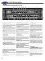
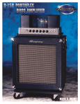
Owners
Owners Guide
Guide for
for the
the
Bass Amplifier
Made with Pride in the U.S.A. by Ampeg ®®
SVT-5 PRO Bass Amplifier
TABLE OF CONTENTS
Introductions . . . . . . . . . . . . . . . . . . . . . . . . . . . . . . . . . . .3
Features . . . . . . . . . . . . . . . . . . . . . . . . . . . . . . . . . . . . . .3
Important Safeguards and Precautions . . . . . . . . . . . . . . .3
The Front Panel Controls and Their Use . . . . . . . . . . . . . .4
The Rear Panel . . . . . . . . . . . . . . . . . . . . . . . . . . . . . . . . .5
Connections: Mono Bridged . . . . . . . . . . . . . . . . . . . . . .6
Dual Mono . . . . . . . . . . . . . . . . . . . . . . . . .6
Biamp - Full Range and Lows . . . . . . . . . .6
Biamp - Highs and Lows . . . . . . . . . . . . . .7
Biamp With a Second Amplifier . . . . . . . . .7
Some Suggested Settings . . . . . . . . . . . . . . . . . . . . . . . . .8
Rack Mounting . . . . . . . . . . . . . . . . . . . . . . . . . . . . . . . . .9
Troubleshooting . . . . . . . . . . . . . . . . . . . . . . . . . . . . . . . .9
System Block Diagram . . . . . . . . . . . . . . . . . . . . . . . . . .10
Technical Specifications . . . . . . . . . . . . . . . . . . .back cover
Declaration Of Conformity
#32, Effective 01-01-2001
Manufacturer’s Name:
Production Facility:
Production Facility:
Shipping Facility:
Office Facility:
SLM Electronics
11880 Borman Drive, St. Louis, MO 63146, USA
700 Hwy 202 W, Yellville, AR 72687, USA
1400 Ferguson Ave., St. Louis, MO 63133, USA
1400 Ferguson Ave., St. Louis, MO 63133, USA
Product Type:
Audio Amplifier
Complies with Standards:
LVD:
Safety:
EMC:
92/31/EEC, 93/68/EEC, & 73/23/EWG
EN60065
EN55013, EN55020, EN55022, EN61000-3-2,
& EN61000-3-3
Supplementary information provided by your local Sales & Services Office or:
SLM Electronics - R & D Engineering
1901 Congressional Drive, St Louis, MO 63146, USA
Tel.: 314-569-0141, Fax: 314-569-0175
CAUTION
PRECAUCION
ATTENTION
RISK OF ELECTRIC SHOCK
DO NOT OPEN
RIESGO DE CORRIENTAZO
NO ABRA
RISQUE D'ELECTROCUTION
NE PAS OUVRIR
WARNING: TO REDUCE THE RISK OF FIRE OR ELECTRIC SHOCK, DO NOT EXPOSE
THIS APPARATUS TO RAIN OR MOISTURE. TO REDUCE THE RISK OF ELECTRIC
SHOCK, DO NOT REMOVE COVER. NO USER-SERVICEABLE PARTS INSIDE. REFER
SERVICING TO QUALIFIED SERVICE PERSONNEL.
PRECAUCION: PARA REDUCIR EL RIESGO DE INCENDIOS O DESCARGAS ELECTRICAS, NO PERMITA QUE ESTE APARATO QUEDE EXPUESTO A LA LLUVIA O LA HUMEDAD. PARA DISMINUOIR EL
RIESGO DE CORRIENTAZO. NO ABRA LA CUBIERTA. NO HAY PIEZAS ADENTRO QUE EL USARIO
PUEDO REPARAR DEJE TODO MANTENIMIENTO A LOS TECHNICOS CALIFICADOS.
ATTENTION: PROTÉGEZ CET APPAREIL DE LA PLUIE ET DE L'HUMIDITÉ AFIN D'ÉVITER TOUT
RISQUE D'INCENDIE OU D'ÉLECTROCUTION. POUR REDUIRE D'ELECTROCUTION NE PAS ENLEVER
LE COUVERCLE. AUCUNE PIECE INTERNE N'EST REPRABLE PAR L'UTILISATEUR. POUR TOUTE
REPARATION, S'ADRESSER A UN TECHNICIEN QUALIFIE.
IMPORTANT SAFETY INSTRUCTIONS
• READ, FOLLOW, HEED, AND KEEP ALL INSTRUCTIONS AND WARNINGS.
• DO NOT OPERATE NEAR ANY HEAT SOURCE AND DO NOT BLOCK ANY VENTILATION OPENINGS ON THIS APPARATUS. FOR PROPER OPERATION, THIS UNIT REQUIRES 3”
(75CM) OF WELL VENTILATED SPACE AROUND HEATSINKS AND OTHER AIR FLOW PROVISIONS IN THE CABINET.
• DO NOT USE THIS APPARATUS NEAR SPLASHING, FALLING, SPRAYING, OR STANDING LIQUIDS.
• CLEAN ONLY WITH LINT-FREE DAMP CLOTH AND DO NOT USE CLEANING AGENTS.
• ONLY CONNECT POWER CORD TO A POLARIZED, SAFETY GROUNDED OUTLET WIRED TO CURRENT ELECTRICAL CODES AND COMPATIBLE WITH VOLTAGE, POWER, AND
FREQUENCY REQUIREMENTS STATED ON THE REAR PANEL OF THE APPARATUS.
•
•
•
•
•
•
PROTECT THE POWER CORD FROM DAMAGE DUE TO BEING WALKED ON, PINCHED, OR STRAINED.
UNPLUG THE APPARATUS DURING LIGHTNING STORMS OR WHEN UNUSED FOR LONG PERIODS OF TIME.
ONLY USE ATTACHMENTS, ACCESSORIES, STANDS, OR BRACKETS SPECIFIED BY THE MANUFACTURER FOR SAFE OPERATION AND TO AVOID INJURY.
WARNING: TO REDUCE THE RISK OF ELECTRIC SHOCK OR FIRE, DO NOT EXPOSE THIS UNIT TO RAIN OR MOISTURE.
SERVICE MUST BE PERFORMED BY QUALIFIED PERSONNEL.
OUR AMPLIFIERS ARE CAPABLE OF PRODUCING HIGH SOUND PRESSURE LEVELS. CONTINUED EXPOSURE TO HIGH SOUND PRESSURE LEVELS CAN CAUSE PERMANENT HEARING IMPAIRMENT OR LOSS. USER CAUTION IS ADVISED AND EAR PROTECTION IS RECOMMENDED IF UNIT IS OPERATED AT HIGH VOLUME.
EXPLANATION OF GRAPHICAL SYMBOLS:
EXPLICACION DE SIMBOLOS GRAFICOS:
EXPLICATION DES SYMBÔLES GRAPHIQUES:
2
"DANGEROUS VOLTAGE"
=
“VOLTAJE PELIGROSO”
"DANGER HAUTE TENSION"
"IT IS NECESSARY FOR THE USER TO REFER TO THE INSTRUCTION MANUAL"
=
“ES NECESARIO QUE EL USUARIO SE REFIERA AL MANUAL DE INSTRUCCIONES.”
"REFERREZ-VOUS AU MANUAL D'UTILISATION"
SVT-5 PRO Bass Amplifier
An Introduction to your new Ampeg SVT-5 PRO Bass Amplifier
Thank you for making one of the best choices you will ever make for your musical career – choosing one of the finest bass
amps available, the Ampeg SVT-5 PRO. This versatile and powerful bass amplifier delivers up to 1350 watts of unsurpassed
musical power, and offers several outstanding features.
All of the features and controls of your SVT-5 PRO are covered in detail in this owner’s guide. We recommend reading about
them prior to using the amplifier.
Features
In the world of high performance bass amps, Ampeg amplifiers stand alone. In true Ampeg tradition, the SVT-5 PRO offers
more power, performance and flexibility than any other bass amplifier in its class. The outstanding features which set your new
amplifier apart from the competition are listed below.
• 15dB PAD SWITCH: Use this to accommodate the input signal from an instrument with active electronics or very “hot” pickups
• MUTE SWITCH: Silences the output signal from the amplifier, allowing you to tune in private
• TWO SEPARATE CHANNELS: Choose between the clean channel, the overdrive channel, or both combined, for the widest variety of sounds possible
• COMPRESSOR SWITCH: Controls the dynamic range of the preamp, to even out your volume level
• ULTRA LOW, ULTRA HIGH AND GAIN BOOST SWITCHES: For additional tonal flexibility – allows
even greater sound control
• VARIABLE MIDRANGE SELECTOR: Custom select the center frequency point for the midrange control
for just the right “voice”
• GATE SWITCH: Keeps things quiet in between riffs
• FOOTSWITCH JACKS: Two jacks allow footswitch control of channel selection/channel combine and
octave/mute
• TWO EFFECTS LOOPS: Allow you to add effects to both channels
• THREE PREAMP OUTPUTS: One for each channel, plus one for the octave signal
• TRANSFORMER-BALANCED XLR OUTPUTS: For connection to a recording console, PA system or
external amplifier
• DUAL SEPARATE POWER AMPLIFIERS: For operation in true stereo or mono bridge mode for maximum power
• BIAMP CAPABILITIES: Low and high output jacks, crossover frequency control, and low to high balance
• TUNER OUT JACK: Allows use of an electronic tuner - active even when the amplifier is muted
• POWER AMP IN JACKS: Allow you to connect a preamp signal to either or both internal amplifiers
• CIRCUIT BREAKER PROTECTION: Provides protection against fault conditions
• OCTAVE CIRCUIT: Adds a signal to the input signal that is one octave lower than the original
• HEAVY DUTY SPEAKER JACKS: Speakon® jacks are provided for both channels and for mono bridge
Important Safeguards and Precautions:
All Ampeg products are designed for continuous safe operation, as long as common sense is used and steps are taken to help avoid certain problems. Abiding by the following rules can help prevent damage to your amplifier, yourself and others.
• The amplifier is equipped with a three-pronged AC power cord. To reduce the risk of electrical shock, NEVER remove or otherwise attempt to defeat the ground pin of the power cord.
• Connect the amplifier ONLY to a properly grounded AC outlet of the proper voltage for your amp.
• Avoid sudden temperature extremes, rain and moisture. Also, avoid sudden and intense impact. (If the unit has been subjected
to any of the preceding abuses, have it looked at by an authorized service center.)
• NEVER set the amplifier on a support that might give out under its weight.
• Always keep the total speaker impedance at or above the rated load.
• Unplug the amplifier before cleaning it. NEVER spray liquid cleaners onto the amplifier. Wipe it with a slightly dampened, lintfree cloth to remove dirt and film.
• Do not use the amplifier if it has sustained damage to the chassis, controls, or power cord. Refer the unit to an authorized service center for inspection.
• Amplifiers capable of producing high volume levels are also capable of inflicting permanent hearing loss or damage, if the exposure to such levels is prolonged. Such damage is progressive and irreversible! Consider using quality hearing protection devices.
Speakon® is a registered trademark of Neutrik USA
3
SVT-5 PRO Bass Amplifier
The Front Panel Controls and Their Use
14
1
4
2
3
4
15
5 6
16
17
18
19
7
8
9
10
20
11
12
21
13
30
22
1. INPUT: Connect your bass guitar here by means
of a shielded instrument cable.
2. -15dB: This switch, when depressed, will attenuate the input signal by 15dB. If your bass has
active pickups, depress this switch to better
accommodate its output signal level.
3. MUTE: This switch, when depressed, mutes all
outputs except the Tuner Out (#54). This allows you
to tune your bass with an electronic tuner without
having to adjust any levels or turn down your house
volume.
NOTE: A footswitch can also be used mute the outputs if this switch is in the “out” position. This switch
remains active when a footswitch is connected.
(See #43, rear panel.)
11. COMPRESSION: This switch, when depressed,
activates the compression circuit which evens out
your volume by governing the gain of the preamp.
The amount of compression is determined by the
setting of the Gain control (#4).
12. COMBINE: This switch, when depressed,
allows the clean channel to remain active when the
overdrive channel is selected, combining the two
channels to create a different-sounding “third channel.” A footswitch connected to the Ch/Combine
jack (#42) overrides this switch.
NOTE: The Channel Select switch (#25) must be
depressed for the Combine function to operate.
13. VOLUME: This control adjusts the output level
for the clean channel.
CLEAN CHANNEL:
4. GAIN: This control adjusts the level of the signal
going to the clean preamp. Adjust this control until
the Peak LED (#5) flashes on strong signal peaks
(but is not continuously illuminated while playing).
To obtain the best signal to noise ratio, set the Gain
control to the highest possible setting and adjust the
clean channel Volume (#13) and Master control
(#23) to obtain the desired volume level.
5. PEAK LED: This LED will illuminate when the
preamp signal approaches its clipping level, indicating optimum gain setting.
6. ULTRA HI: This switch, when depressed,
increases the high frequency output by 7dB at
15kHz.
7. ULTRA LO: This switch, when depressed,
increases the low frequency output by 5dB at 30Hz.
8. BASS: This control provides an adjustment
range of 20dB at 40Hz.
9. MID: This control provides an adjustment range
21dB at 300Hz.
10. TREBLE: This control provides an adjustment
range of 18dB at 10kHz.
OVERDRIVE CHANNEL:
14. GAIN: This control adjusts the level of the signal going to the overdrive preamp. As this control is
increased, so is the amount of overdrive distortion
added to your sound.
15. BOOST: This switch, when depressed, adds
gain and tone shaping to the overdrive channel signal for heavy distortion.
16. GATE: This switch, when depressed, activates
a noise gate which keeps the overdrive channel
silent when no input signal is present.
17. BASS: This control provides an adjustment of
12dB of cut or boost at 100Hz.
18. MID: This control provides an adjustment of
5dB of cut or 20dB of boost at 300Hz - 2kHz,
depending on the setting of the Frequency control
(#19).
19. FREQUENCY: This control adjusts the center
frequency of the Mid control (#18), from 300Hz at
the fully counterclockwise position to 1.5kHz at the
fully clockwise position.
20. TREBLE: This control provides an adjustment
of 12dB of cut or boost at 7kHz.
23 24 25 26 27
28
29
21. VOLUME: This control adjusts the output level
for the overdrive channel.
22. OCTAVE: This control adjusts the output level
for an added signal which is one octave lower than
the instrument’s original signal. This signal is
dependent on the clean channel’s Gain control (#4)
and can be switched on and off by means of a
footswitch connected to the Octave/Mute jack
(#43). The effectiveness of this signal depends on
playing style, pickup selection and neck position.
23. MASTER: This control adjusts the overall output level of the amplifier.
24. LIMIT: This LED illuminates when the internal
limit circuit is activated. This indicates that the
amplifier is nearing full output and the limiter is
keeping it from clipping the output signal.
25. CHANNEL SELECT: This switch selects the
clean channel in the out position and the overdrive
channel when depressed. A footswitch connected
to the Ch/Combine jack (#42) overrides this switch.
26. LIMIT DEFEAT: This switch, when depressed,
deactivates the internal limit circuit. This may allow
an increase in output power, but the signal may be
distorted. A distorted signal at high output levels
could damage the components of your speaker
system. Use discretion when playing with the limiter
deactivated to avoid damaging your speakers.
27. OD/CLEAN LEDS: These LEDs indicate which
channel is selected.
28. CROSSOVER FREQUENCY: This control
determines the crossover frequency between the
Biamp High and Biamp Low Output jacks (#44).
29. CROSSOVER BALANCE: This control adjusts
the relative levels between the Biamp High and
Biamp Low Output jacks (#44).
30. POWER: This switch applies power to the
amplifier: the amp is ON when the top of the switch
is depressed, OFF when the bottom of the switch is
depressed.
SVT-5 PRO Bass Amplifier
The Rear Panel
31
44
45
46
47
48
49
50
51
52
53
54
CLEAN POST
CLEAN PRE
OVERDRIVE
MIX
*
SVT5PRO
32
33
31. AC OUTLET: This unswitched outlet provides a
convenient source of AC power for effects units, an
electronic tuner, power amplifier, etc. The outlet is “live”
whenever the amplifier is plugged into an active AC
power outlet, regardless of the setting of the amplifier’s
Power switch. The total current draw of the components
connected to this outlet must not exceed 300 watts.
32. CIRCUIT BREAKER: The SVT-5 PRO employs an
AC line circuit breaker to help protect against damage
due to excessive current demands. If the amplifier stops
working, check the circuit breaker. If it has opened, the
button will protrude showing a contrasting color. Reset
the circuit breaker by depressing it until it latches. The
breaker must cool down for a short time before the button will latch. If the circuit breaker opens repeatedly, have
the amplifier checked by a qualified service person.
33. AC LINE IN: Firmly insert the female end of the supplied AC power cord into this socket. The grounded
power cord should only be plugged into a grounded
power outlet that meets all applicable electrical codes
and is compatible with the voltage, power, and frequency requirements stated on the rear panel. Do not
attempt to defeat the safety ground connection.
34. SPEAKER OUTPUTS: Connect the amplifier to
your speaker cabinet(s) using heavy gauge speaker
cables terminated with the appropriate connectors. The
Speakon® jacks are recommended when playing at full
output levels, and must be used in the Mono Bridge
mode. Refer to the text printed on the rear panel to the
left of the Speakon® jacks for pinout information.
35: FULL RANGE/BIAMP: This switch determines
how the input signal is routed to the internal amplifiers.
With the switch in the Full Range position (switch out) a
full range signal is sent to both internal amp channels.
With the switch in the Biamp position (switch depressed)
the low frequencies are routed to power amp A and the
high frequencies are routed to power amp B.
36. STEREO/MONO: This switch determines the operating mode of the internal amplifiers. With the switch in
the Stereo position (switch out) the two internal amplifiers operate independently from each other. With the
switch in the Mono position (switch depressed) the two
internal amplifiers are bridged together and operate as a
single amplifier with higher output power.
37. OVERDRIVE PREAMP OUTPUT: Use this jack to
send a direct preamp signal from the overdrive channel
to one of the internal amplifiers, an external power amplifier, a mixing console, or a recording device.
34
37
35 36
38
38. CLEAN/MIX / SEPARATE: This switch determines
the routing and mixing of the preamp output signals.
With the switch in the out position the signals are mixed
together and sent to the power amplifiers. When the
switch is depressed the outputs are separated: Clean to
Amp A and Overdrive to Amp B.
39. CLEAN/MIX PREAMP OUTPUT: Use this jack to
send the preamp signal from the clean channel or a mixture of the clean and overdrive channels (as determined
by the setting of the Clean/Mix / Separate switch) to one
of the internal amplifiers, an external power amplifier, a
mixing console, or a recording device.
40. OCTAVE PREAMP OUTPUT: Use this jack to send
a direct preamp signal from the octave circuit to one of
the internal amplifiers, an external power amplifier, mixing console, or recording device. Using this jack will
remove the Octave signal from the Clean/Mix output
(#39). You may also use this jack as a patch point into
the octave circuit, as if it were an Insert jack. Use a
stereo Y-cable: tip = send, ring = return, sleeve = ground.
41. POWER AMP INPUTS: Use these jacks to connect
the signal from an external source directly into one of the
internal power amps. The preamp outputs are disconnected from the power amps when these jacks are
used. In the Mono Mode, Amp A = Input. In the Biamp
mode, Amp A = Low Input, Amp B = High Input. (See
pages 6 and 7.)
42. CH/COMBINE FOOTSWITCH: This jack allows
you to use a two-button footswitch (such as the Ampeg
AFP-2) or 1/2 of a four-button foot-switch (such as the
Ampeg AFP-4B) to control channel selection and combination. The jack is wired as follows: Tip = channel
select, Ring = combine. The front panel Channel Select
(#25) and Combine (#12) controls are bypassed when
a footswitch is connected to this jack.
43. OCTAVE/MUTE FOOTSWITCH: This jack allows
you to use a two-button footswitch (such as the Ampeg
AFP-2) or 1/2 of a four-button foot-switch (such as the
Ampeg AFP-4B) to control the octave signal and mute
function. The jack is wired as follows: Tip = octave, Ring
= mute. The front panel Mute (#3) control remains active
when a footswitch is connected to this jack.
44. BIAMP HIGH, BIAMP LOW OUTPUTS: These
jacks provide separate low and high frequency preamplified signals for use in the biamp mode. (See
pages 6 and 7.)
39
41
40
42
43
45. LIFT/GND: With this switch in the out position the
ground pins of the Balanced Line Output jacks (#46,
#49) is interrupted. This may help reduce residual hum
and buzz which is sometimes picked up by line out signal cables.
46. OD/MIX LINE OUT: Use this jack to send a transformer balanced line output signal from the overdrive
channel to an external amplifier, mixing console or
recording equipment. When the Overdrive/Mix switch
(#48) is depressed, this jack sends a line out signal from
both channels.
47. CLEAN POST/CLEAN PRE: This switch determines whether the signal at the Clean Line Out jack
(#49) is post EQ (switch out) or pre EQ (switch
depressed). The pre EQ signal may be used as a Direct
Input signal.
48. OVERDRIVE/MIX: This switch determines whether
the signal at the OD/Mix Line Out jack (#46) is the
Overdrive channel (switch out) or a combination of both
channels (switch depressed).
49. CLEAN OUT: Use this jack to send a transformer
balanced line output signal from the clean channel to an
external amplifier, mixing console or recording equipment. The source is determined by the setting of the
Clean Post/Clean Pre switch (#47).
50. OVERDRIVE EFFECTS LOOP RETURN: When
using an external effect on the Overdrive channel, connect the effect’s output into this jack by means of a
shielded signal cable.
51. OVERDRIVE EFFECTS LOOP SEND: When
using an external effect on the Overdrive channel, connect this jack to the effect’s input by means of a shielded signal cable.
52. CLEAN EFFECTS LOOP RETURN: When using
an external effect on the Clean channel, connect the
effect’s output into this jack by means of a shielded signal cable.
53. CLEAN EFFECTS LOOP SEND: When using an
external effect on the Clean channel, connect this jack to
the effect’s input by means of a shielded signal cable.
54. TUNER OUT: Use this jack to connect an electronic tuner to the amplifier. The signal at this jack is always
present, even when the Mute is engaged, allowing for
silent tuning as well as a non-interrupted monitor feed.
5
SVT-5 PRO Bass Amplifier
Connections
MONO BRIDGED: The SVT-5 PRO’s two internal amplifiers are bridged together to produce maximum output power.
• Full Range/Biamp switch out (full range), Stereo/Mono switch depressed (mono)
• Connect a heavy duty speaker cable () from the SVT-5 PRO’s Mono Bridge/Biamp Speakon® jack to the input of a full range speaker cabinet
• Speakon® pin 1 + = signal “+,” pin 2+ = signal “–”
SVT-5 PRO
FULL RANGE
CABINET(S)
Mono
Bridged
MONO
BRIDGE
1
OUT (FULL
RANGE)
IN
(MONO)
TO
INPUT
JACK
NOTE: BE
ABSOLUTELY
CERTAIN THAT
THE CABINET(S)
ARE ABLE TO
HANDLE THE
EXTREMELY
HIGH OUTPUT
POWER OF THE
AMP IN THIS
MODE!
DUAL MONO: The SVT-5 PRO’s two internal amplifiers will each power a full range cabinet.
• Full Range/Biamp switch out (full range), Stereo/Mono switch out (stereo)
• Connect a heavy duty speaker cable () from the SVT-5 PRO’s Power Amp A jack to the input of a full range speaker cabinet
• Connect a heavy duty speaker cable () from the SVT-5 PRO’s Power Amp B jack to the input of a full range speaker cabinet
SVT-5 PRO
Dual
Mono
PWR
AMP B
2
PWR
AMP A
FULL RANGE
CABINET(S)
1
OUT (FULL
RANGE)
TO
INPUT
JACK
OUT
(STEREO)
FULL RANGE
CABINET(S)
TO
INPUT
JACK
BIAMP - Full Range / Lows: One of the SVT-5 PRO’s internal amplifiers will power a full range cabinet, the other will power a low frequency cabinet.
• Full Range/Biamp switch out (full range), Stereo/Mono switch out (stereo)
• Connect a signal cable () from the SVT-5 PRO’s Biamp Low Output jack to its Amp A Power Amp Input jack
• Connect a heavy duty speaker cable () from the SVT-5 PRO’s Power Amp A jack to the input of a low frequency speaker cabinet
• Connect a heavy duty speaker cable () from the SVT-5 PRO’s Power Amp B jack to the input of a full range speaker cabinet
SVT-5 PRO
Biamp - Full
Range / Lows
BIAMP
LO OUT
PWR
AMP B
3
PWR
AMP A
2
OUT
OUT
(STEREO)
(FULL
RANGE)
AMP A
PWR
AMP
INPUT
1
FULL RANGE
CABINET(S)
TO
INPUT
JACK
LOW FREQ.
CABINET(S)
Use the Crossover Frequency control (#28)
to set the crossover point for the low output.
6
TO
INPUT
JACK
SVT-5 PRO Bass Amplifier
Connections
BIAMP - Highs / Lows: One of the SVT-5 PRO’s internal amplifiers will power a high frequency cabinet, the other will power a low frequency cabinet.
• Full Range/Biamp switch depressed (biamp), Stereo/Mono switch out (stereo)
• Connect a heavy duty speaker cable () from the SVT-5 PRO’s Power Amp A jack to the input of a low frequency speaker cabinet
• Connect a heavy duty speaker cable () from the SVT-5 PRO’s Power Amp B jack to the input of a high frequency speaker cabinet
– OR –
• Connect a heavy duty four-conductor speaker cable () from the SVT-5 PRO’s Mono Bridge/Biamp Speakon® jack to the input of a biamp-equipped speaker cabinet
• Speakon® pin 1 + = low “+,” pin 1– = low “–,” pin 2+ = high “+,” pin 2– = high “–”
SVT-5 PRO
Biamp Highs / Lows
PWR
AMP B
2
BIAMP
PWR
AMP A
3
HIGH FREQ.
CABINET(S)
1
IN (BIAMP)
TO
INPUT
JACK
OUT
(STEREO)
Use the Crossover Frequency control (#28)
to set the crossover point for the high and
low outputs.
LOW FREQ.
CABINET(S)
BIAMPEQUIPPED
CABINET
TO
INPUT
JACK
TO
"BIAMP MODE"
SPEAKON® JACK
BIAMP WITH A SECOND AMP: The SVT-5 PRO’s two internal amplifiers will each power a low frequency cabinet. A second amplifier will power a
high frequency cabinet.
• Full Range/Biamp switch out (full range), Stereo/Mono switch depressed (mono)
• Connect a signal cable () from the SVT-5 PRO’s Biamp High Output jack to the input jack of the second power amp
• Connect a signal cable () from the SVT-5 PRO’s Biamp Low Output jack to its Amp A Power Amp Input jack
• Connect a heavy duty speaker cable () from the second power amp’s Speaker Output jack jack to the input of a high frequency speaker cabinet
• Connect a heavy duty speaker cable () from the SVT-5 PRO’s Mono Bridge jack to the input of a low frequency speaker cabinet
• Speakon® pin 1 + = signal “+,” pin 2+ = signal “–”
Biamp with a
Second Amp
SVT-5 PRO
BIAMP
HI OUT
BIAMP
LO OUT
1
MONO
BRIDGE
2
4
OUT
(FULL
RANGE)
IN
SVT-5 PRO
OR OTHER
POWER AMP
AMP A
PWR
AMP
INPUT
(MONO)
HIGH FREQ.
CABINET(S)
MONO
BRIDGE
3
OUT
IN
AMP A
PWR
AMP
INPUT
TO
INPUT
JACK
(FULL
RANGE)
LOW FREQ.
CABINET(S)
(MONO)
TO
INPUT
JACK
Use the Crossover Frequency control (#28)
to set the crossover point for the high and
low outputs.
7
SVT-5 PRO Bass Amplifier
Some Suggested Settings
OUT
"SVT"
OUT
"SMOOTH"
OUT
IN
OUT
OUT
IN
OUT
"METAL"
IN
"SLAPPIN'"
IN
OUT
IN
OUT
OUT
OUT
"EDGE"
OUT
OUT
IN
IN
OUT
IN
OUT
IN
"SYNTH"
IN
OUT
IN
IN
OUT
IN
OUT
IN
"THREE GUYS
JAMMIN'"
IN
8
OUT
IN
IN
OUT
IN
OUT
SVT-5 PRO Bass Amplifier
Rack Mounting
When mounting the SVT-5 PRO into a rack, the four
bottom feet should be removed to maintain the three
rack space height of the amplifier. Be sure to keep the
feet and their attachment bolts for future use. If the feet
are reinstalled, never use screws which will protrude
farther into the amplifier than the original hardware.
The rack must be a high quality enclosure capable of
securely supporting the weight of the amplifier. Tighten
the mounting screws securely through the amplifier’s
face plate, into the rack rails. Check the rack and
mounting screws occasionally to ensure a continually
safe and secure installation.
Troubleshooting
In the unlikely event that your SVT-5 PRO should malfunction, take a few minutes to troubleshoot it before you
call for service. You can save yourself time and money by doing it yourself, and often the cure for the problem is
something quite simple.
NO SOUND
POOR SOUND
LEDs LIGHT
LEDs DON'T LIGHT
Check bass, cables
Check amp controls, check
for signal from bass
Check AC outlet
POOR SOUND
OUTLET OK NO POWER
Check speaker(s)
NO SOUND
SOUND OK
SOUND OK
Listen for hum
NO HUM
HUM
Check speaker
Unplug bass,
touch tip of cable
Check amp's power Check house fusebox
cord, circuit breaker, or circuit breaker
power switch
OK
SPEAKER(S) OK,
POOR SOUND
SPEAKER(S)
DEFECTIVE
Replace speaker(s)
POOR SOUND
SOUND OK
Speaker OK
NO CHANGE
SOUND OK
Replace cable
NO CHANGE
SEE BELOW
SEE BELOW
If the problem isn’t covered above, or if the steps lead you here, then contact your Ampeg dealer for service information. Also, you should refer your amp for servicing if it gets dropped, has liquid spilled into it, or sustains damage
to its power cord (see page 3).
9
10
INPUT
MUTE
OUT
MIX/SEP.
FOOTSWITCH
-15dB PAD
TUNER
OUT
TONES
BAL
BOOST
GAIN
LOW
HIGH
BASS MID TREBLE
BIAMP
XOVER
FREQ
TUBE
STAGE
PEAK/
MUTE
FULL RANGE/
BIAMP
OUT
BASS
TREBLE
ULTRA
LOW ULTRA
HIGH
GAIN
STEREO/
MONO
OUT
MID
FREQ.
ON
CMPRSN
PWR
AMP B
IN
PWR
AMP A
IN
GATE
EFFECTS
LOOP
EFFECTS
LOOP
OCTAVE
VOLUME
LIMITER
LIMIT
LIMITER
LIMIT
DEFEAT
COMBINE
CH. SELECT
VOLUME
OCTAVE
FOOTSWITCH
LOGIC
OCTAVE
POWER
AMP B
POWER
AMP A
MASTER
SPKR
OUT
(B)
SPKR
OUT
(B)
SPKR
OUT
(A)
SPKR
OUT
(A)
1-
1-
1-
2+
1+
2+
1+
2+
1+
SPEAKON
JACK
(MONO
BRDG/
BIAMP)
SPEAKON
JACK
(A)
OD/MIX
OUT
OD
MIX
OUT
2- SPEAKON
JACK
(B)
2-
2-
OVERDRIVE
PREAMP
OUT
SWITCHING
JACK
PRE/POST
PRE IN
CLEAN (POST)
CLEAN/MIX
PREAMP
OUT
OCTAVE
PREAMP
OUT
GND LIFT
OUT
OD/MIX
BAL. OUT
CLEAN
BAL. OUT
SVT-5 PRO Bass Amplifier
System Block Diagram
SVT-5 PRO Bass Amplifier
11
SVT-5 PRO Bass Amplifier
Technical Specifications
OUTPUT POWER RATING
TONE CONTROL RANGE
Clean Channel
Bass:
Midrange:
Treble:
Ultra Low:
Ultra High:
Overdrive Channel
Bass:
Midrange:
Treble:
SIGNAL TO NOISE RATIO
COMPRESSION RATIO
FOOTSWITCH JACKS
Ch/Combine:
Octave/Mute:
POWER REQUIREMENTS
Domestic:
Export:
SIZE AND WEIGHT
1350 Watts Mono-Bridged @ 4 Ohms (1000 Watts Continuous)
840 Watts Mono-Bridged @ 8 Ohms (680 Watts Continuous)
2 x 675 Watts @ 2 Ohms (500 Watts Continuous)
2 x 420 Watts @ 4 Ohms (340 Watts Continuous)
2 x 255 Watts @ 8 Ohms (205 Watts Continuous)
20dB range @ 40Hz
21dB range @ 300Hz
18dB range @ 10kHz
+5dB @ 30Hz
+7dB @ 15kHz
±12dB @ 100Hz
+20dB, -5dB @ 300 – 1.5kHz
±12dB @ 7kHz
75dB typical
4:1 (1dB change in output for 4dB change in input)
Tip = channel select, Ring = combine
Tip = Octave, Ring = Mute
120VAC, 60Hz, 800VA
100/115VAC 50/60Hz, 800VA
230VAC, 50/60Hz, 800VA
19/17.4”W x 5.6”H (with feet) x 15.5”D; 40 lbs
Ampeg reserves the right to change specifications without notice.
Ampeg – The Power of Bass
www.ampeg.com
Made with Pride in the U.S.A. by Ampeg • ©2001 AMPEG, 1400 Ferguson Avenue, St. Louis, MO 63133 U.S.A.
P/N 47-618-51 • 012703