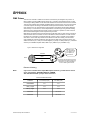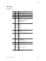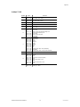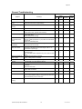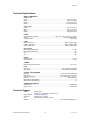
1
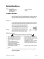
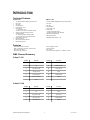
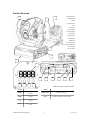
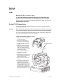
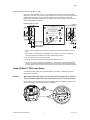
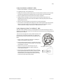
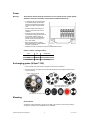
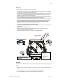
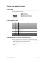
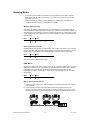
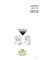
Q-SPOT250 Q-Spot™ 250 Q-WASH250 Q-Wash™ 250 USER MANUAL Q-Spot™ 250 Q-Wash™ 250 CHAUVET, 3000 N 29th Ct, Hollywood, FL 33020 U.S.A (800) 762-1084 – (954) 929-1115 FAX (954) 929-5560 www.chauvetlighting.com 2005-10-09/22:09 Table of Content BEFORE YOU BEGIN....................................................................................................................................................... 3 WHAT IS INCLUDED .......................................................................................................................................................................................................... 3 UNPACKING INSTRUCTIONS .............................................................................................................................................................................................. 3 AC POWER ..................................................................................................................................................................................................................... 3 SAFETY INSTRUCTIONS .................................................................................................................................................................................................... 3 INTRODUCTION ............................................................................................................................................................... 4 TECHNICAL FEATURES ..................................................................................................................................................................................................... 4 FEATURES ....................................................................................................................................................................................................................... 4 DMX CHANNEL SUMMARY ............................................................................................................................................................................................... 4 Q-Spot™ 250 ........................................................................................................................................................................................................... 4 Q-Wash™ 250 ......................................................................................................................................................................................................... 4 PRODUCT OVERVIEW....................................................................................................................................................................................................... 5 SETUP .............................................................................................................................................................................. 6 LAMP ............................................................................................................................................................................................................................. 6 Maximizing the life of your lamp......................................................................................................................................................................... 6 (Q-SPOT™ 250) LAMP SETUP ......................................................................................................................................................................................... 6 Lamp Installation (Q-Spot™ 250)....................................................................................................................................................................... 6 Lamp Alignment How-To (Q-Spot™ 250) .......................................................................................................................................................... 7 LAMP (Q-WASH™ 250) LAMP SETUP ............................................................................................................................................................................... 7 Lamp Installation (Q-Wash™ 250)..................................................................................................................................................................... 8 Lamp Alignment How-To (Q-Wash™ 250) ........................................................................................................................................................ 8 POWER ........................................................................................................................................................................................................................... 9 EXCHANGING GOBOS (Q-SPOT™ 250)............................................................................................................................................................................. 9 MOUNTING ...................................................................................................................................................................................................................... 9 OPERATING INSTRUCTIONS ........................................................................................................................................ 11 CONTROL PANEL ........................................................................................................................................................................................................... 11 CONTROL PANEL FUNCTIONS......................................................................................................................................................................................... 11 APPLYING CHANGES TO FUNCTIONS (QUICK INSTRUCTIONS) .......................................................................................................................................... 11 OPERATING MODES ....................................................................................................................................................................................................... 12 Master/Stand Alone.......................................................................................................................................................................................... 12 Setting Slave Fixtures ...................................................................................................................................................................................... 12 DMX Mode........................................................................................................................................................................................................ 12 Daisy Chain Connection................................................................................................................................................................................... 12 DMX-512 addressing ............................................................................................................................................................................................. 13 Setting the starting address ............................................................................................................................................................................. 13 User Configurations ............................................................................................................................................................................................... 13 Pan Invert & Tilt Invert...................................................................................................................................................................................... 13 Color Wheel (split colors) ................................................................................................................................................................................. 13 Service Functions .................................................................................................................................................................................................. 13 Fixture Reset (all motors)................................................................................................................................................................................. 13 APPENDIX ...................................................................................................................................................................... 14 DMX PRIMER ................................................................................................................................................................................................................ 14 Fixture Linking .................................................................................................................................................................................................. 14 DMX VALUES ................................................................................................................................................................................................................ 15 Q-Spot™ 250 ......................................................................................................................................................................................................... 15 Q-Wash™ 250 ....................................................................................................................................................................................................... 16 MAINTENANCE ............................................................................................................................................................................................................... 17 RETURNS PROCEDURE .................................................................................................................................................................................................. 17 CLAIMS ......................................................................................................................................................................................................................... 17 GENERAL TROUBLESHOOTING ....................................................................................................................................................................................... 18 TECHNICAL SPECIFICATIONS .......................................................................................................................................................................................... 19 TECHNICAL SUPPORT .................................................................................................................................................................................................... 19 Q-Wash & Q-Spot 250 User Manual 2 2005-10-09/22:09 BEFORE YOU BEGIN What is included Q-SPOT250, Q-Spot™ 250 or Q-WASH250, Q-Wash™ 250 5 extra gobos (Q-Spot™) Power cord with plug HSD-250 Discharge lamp Manual Warranty Card Unpacking Instructions Immediately upon receiving a fixture, carefully unpack the carton, check the contents to ensure that all parts are present, and have been received in good condition. Notify the shipper immediately and retain packing material for inspection if any parts appear damaged from shipping or the carton itself shows signs of mishandling. Save the carton and all packing materials. In the event that a fixture must be returned to the factory, it is important that the fixture be returned in the original factory box and packing. AC Power To determine the power requirements for a particular fixture, see the label affixed to the back plate of the fixture or refer to the fixture’s specifications chart. A fixture’s listed current rating is its average current draw under normal conditions. All fixtures must be powered directly off a switched circuit and cannot be run off a rheostat (variable resistor) or dimmer circuit, even if the rheostat or dimmer channel is used solely for a 0% to 100% switch. Before applying power to a fixture, check that the source voltage matches the fixture’s requirement. Check the fixture or device carefully to make sure that if a voltage selection switch exists that it is set to the correct line voltage you will use. Warning! Verify that the internal multi-tap transformer is set to match the line voltage applied. All fixtures must be connected to circuits with a suitable Earth Ground. Safety Instructions Please read these instructions carefully, which includes important information about the installation, usage and maintenance? Please keep this User Guide for future consultation. If you sell the unit to another user, be sure that they also receive this instruction booklet. Always make sure that you are connecting to the proper voltage and that the line voltage you are connecting to is not higher than that stated on decal or rear panel of the fixture. This product is intended for indoor use only! To prevent risk of fire or shock, do not expose fixture to rain or moisture. Make sure there are no flammable materials close to the unit while operating. The unit must be installed in a location with adequate ventilation, at least 50cm (20in) from adjacent surfaces. Be sure that no ventilation slots are blocked. Always disconnect from power source before servicing or replacing lamp or fuse and be sure to replace with same lamp source. Caution! Secure fixture to fastening device using a safety chain. Never carry the fixture solely by its head. Use its carrying handles. Maximum ambient temperature is Ta: 40°. Do not operate fixture at temperatures higher than this. In the event of serious operating problem, stop using the unit immediately. Never try to repair the unit by yourself. Repairs carried out by unskilled people can lead to damage or malfunction. Please contact the nearest authorized technical assistance center. Always use the same type spare parts. Don’t connect the device to a dimmer pack. Make sure power cord is never crimped or damaged. Never disconnect power cord by pulling or tugging on the cord. Avoid direct eye exposure to lamp while it is on. There are no user serviceable parts inside the unit. Do not open the housing or attempt any repairs yourself. In the unlikely event your unit may require service, please contact CHAUVET. Q-Wash & Q-Spot 250 User Manual 3 2005-10-09/22:09 INTRODUCTION Technical Features Q-Spot™ 250 Q-Wash™ 250 13 channel DMX Intelligent Moving Yoke Pan: 530° Tilt: 280° Pan/Tilt speed Lamp on/off, reset Color Wheel - 7 colors plus white - Rainbow color spin at variable speeds 3-facet high speed rotating prism Rotating Gobos - 5 interchangeable rotating gobos - Gobo wheel spin at variable speeds Gobo rotation channel Motorized focus Mechanical Shutter/Strobe Mechanical Dimmer 10 channel DMX Intelligent Moving Yoke Color Wash Pan: 530° Tilt: 280° Pan/Tilt speed Lamp on/off, reset Color Wheel - 8 dichroic colors plus white - Rainbow color spin in both directions Mechanical Shutter/Strobe Mechanical Dimmer Adjustable beam angle 8° ~ 22° Features - Automatic Pan/Tilt correction Built in automatic programs (stand-alone) Pan/Tilt invert option 16 bit Pan/Tilt resolution - Micro-stepping motors Thermal switch Fan cooled Free extra gobos (Q-Spot™ ) 4 Metal, 1 Glass DMX Channel Summary Q-Spot™ 250 CHANNEL FUNCTION CHANNEL FUNCTION 1 Pan 8 Prism 2 Tilt 9 Rotating Gobos 3 Pan (Fine) 16 bit 10 Gobo rotation 4 Tilt (Fine) 16 bit 11 Focus 5 Pan/Tilt Speed 12 Shutter/Strobe 6 Lamp on/off & reset 13 Dimmer 7 Colors CHANNEL FUNCTION CHANNEL FUNCTION 1 Pan 6 Lamp on/off & reset 2 Tilt 7 Colors 3 Pan (Fine) 16 bit 8 No Function 4 Tilt (Fine) 16 bit 9 Shutter/Strobe 5 Pan/Tilt Speed 10 Dimmer Q-Wash™ 250 Q-Wash & Q-Spot 250 User Manual 4 2005-10-09/22:09 Product Overview 2 2 1. Moving yoke arm 1 2. Projector head 3. Base 4. Carrying handle 5. Fan 7. LED display 8. [Enter] button 9. [Choose] button 10. [Up] button 11. [Down] button 12. DMX output 13. DMX input 14. Carrying handle 15. AC input IEC 60320 C14 16. Fuse holder 4 17. Power switch 5 3 7 12 8 9 10 13 14 15 16 17 11 SEGMENT BUTTONS I/O PANEL OVERVIEW BUTTONS I/O PANEL MODE Toggles programming functions DMX Out & In DMX-512 connectors DOWN Steps backward through menu functions Power AC input IEC 60320 C14 and fuse holder UP Steps forward through menu functions ENTER Confirms selected menu function Q-Wash & Q-Spot 250 User Manual 5 2005-10-09/22:09 SETUP LAMP M axim iz in g t h e li f e o f you r l a mp To ensure the longest and most efficient use of the lamp always wait between 10 and 15 minutes before re-applying power after a shutdown. Failure to do so could result in premature aging of the lamp and failure to the electronics that drive it. (Q-Spot™ 250) Lamp Setup You will need to install a lamp prior to the initial operation of the fixture. A HSD250 high intensity discharge lamp is included. Warning! When replacing the lamp, please wait 15 minutes after powering down to allow the unit to cool down! Always disconnect from main power prior to lamp replacement. Do not touch the envelope (glass area) of the bulb with bare hands. If this happens, clean the lamp with alcohol and wipe it with a lint free cloth before installation. L am p In st a ll at io n ( Q - Spot ™ 2 5 0) Top Cover 1. Remove all 3 screws located on the top cover of the fixture. 2. Remove the 2 thumbscrews to remove lamp cover as illustrated. Lamp cover thumbscrews 3. If replacing the lamp, remove old lamp first. 4. Holding the new lamp by its base, align the pins on the lamp with the holes in the socket and insert the lamp squarely until the lamp socket secures the lamp tightly. 5. Clean the glass/envelope of the bulb with an alcohol wipe or equivalent. 6. Replace lamp cover, align the screw holes and fasten the thumbscrews back onto the lamp cover. 7. Replace top cover and fasten with screws. 8. Turn the fixture on and adjust the lamp alignment screws until the brightest most even area of the beam is in the center of your spot. It may be necessary for you to use a controller in order to command the fixture to display a white beam on a flat surface with no gobos or colors. Q-Wash & Q-Spot 250 User Manual 6 2005-10-09/22:09 Setup Lamp Alignment How-To (Q-Spot™ 250) Often, after a new installation of a lamp, you will find that there is an uneven field of light or what is referred to as a hot spot. This is due to the most intense point of the lamp source not being positioned optimally within the reflector. There are two lamp alignment screws provided at the rear of the projector head. Turning these screws allow you to optimize the projection quality of the spot as well as the overall intensity of the beam. Optimum distance 1 to 1.5mm Incorrect! Keep optimum distance 1-1,5mm WARNIN G! La mp is hot! Ris k of fire P rotec hands and eyes. Wait a l eas 15min B efore o pening the covers and removing lamp from the fi xtur e. Minimum distance to li ght ed object: M axim um room temperature t=45 Minimum distance f rom flammabl e material d=0.5m. Ex terior surf ace tem perature T =80 . No for domestic us e. A djust lamp posit ion by turning screws and Be sure t hat the lamp bulb never to uch the lens B A Screw B Di sconnect t he fixture from AC power be fore re-lam ping. Screw A 1. Project a white spot against any flat surface. Preferably the surface should be white or pastel in color. 2. Adjust screw A to achieve optimum lamp distance from reflector of 1 to 1.5mm as illustrated above. If the hotspot is too defined, turn screw A to distribute light evenly. 3. You can center the hot spot by turning screw B. 4. It may be necessary to jump back and forth between step 2 and step 3. 5. As you move in and out of optimum lamp alignment, you will see the hot spot either get wider or narrower. The goal is to either totally diminish the hot spot by having it widen and spread across the entire spot or moving the hot spot so that it covers as much of the beam spot area as possible. Lamp (Q-Wash™ 250) Lamp Setup You will need to install a lamp prior to the initial operation of the fixture. A HSD250 high intensity discharge lamp is included. Warning! When replacing the lamp, please wait 15 minutes after powering down to allow the unit to cool down! Always disconnect from main power prior to lamp replacement. Do not touch the envelope (glass area) of the bulb with bare hands. If this happens, clean the lamp with alcohol and wipe it with a lint free cloth before installation. B X Z WARNING! Wait at least 15 min. before opening the covers and removing Screws X,Y, Z A C Ex Q-Wash & Q-Spot 250 User Manual 7 te r io rs Y urfa c e tem p e r a tu re T =8 C 0° 2005-10-09/22:09 Setup L am p In st a ll at io n ( Q - W as h™ 2 5 0) 1. Remove screws labeled X, Y and Z and pull out lamp socket plate. 2. If replacing the lamp, remove old lamp first. 3. Holding the new lamp by its base, align the pins on the lamp with the small hole in the socket and insert the lamp squarely until the retaining clips on the lamp socket secure the lamp tightly. 4. Clean the glass/envelope of the bulb with an alcohol wipe or equivalent. 5. Holding the lamp socket plate, insert the tip of the lamp into the fixture with extreme care. Navigate the lamp all the way until it reaches the reflector and the lamp base plate touches the bottom plate of the fixture. 6. Align the screw holes and fasten the screws back onto the lamp socket plate. 7. Turn the fixture on and adjust the lamp alignment screws until the brightest most even area of the beam is in the center of your spot. It may be necessary for you to use a controller in order to command the fixture to display a white beam on a flat surface with no colors. L am p Al i g n men t How - T o ( Q - W a sh ™ 2 50) Often, after a new installation of a lamp, you will find that there is an uneven field of light or what is referred to as a hot spot. This is due to the most intense point of the lamp source not being positioned optimally within the reflector. There are three lamp alignment screws provided at the base of the projector head. Turning these screws allow you to optimize the projection quality of the spot as well as the overall intensity of the beam. X Z WARNING! Wait at least 15 min. before opening the covers and removing 1. Project a white spot against any flat surface. Preferably the surface should be white or pastel in color. A 2. Turning the lamp alignment screws, try to position the hot spot in the center of the beam as best as possible. This could require many attempts on your part. 3. Once the hot spot is in the center of the spot, do your best to turn all screws equally as to affect movement up or down within the reflector. B C Ex te r io rs Y u rf a c e tem p e r a tu re T =8 C 0° Lamp Alignment Screws, A, B & C 4. As you move in and out of optimum lamp focus, you will see the hot spot either gets wider or narrower. The goal is to either totally diminish the hot spot by having it widen and spread across the entire spot or moving the hot spot so that it covers as much of the beam spot area as possible. Q-Wash & Q-Spot 250 User Manual 8 2005-10-09/22:09 Power Warning! Verify that the internal multi-tap transformer is set to match the line voltage applied. All fixtures must be connected to circuits with a suitable Earth Ground. To determine the power requirements for a particular fixture, see the label affixed to the back plate of the fixture or refer to the fixture’s specifications chart. A fixture’s listed current rating is its average current draw under normal conditions. All fixtures must be powered directly off a switched circuit and cannot be run off a rheostat (variable resistor) or dimmer circuit, even if the rheostat or dimmer channel is used solely for a 0% to 100% switch. Before applying power to a fixture, check that the source voltage matches the fixture’s requirement. All fixtures must be connected to circuits with a suitable Earth Ground. Po w e r Ca b l e Co nf igu ra t io n CABLE PIN BROWN Live INTERNATIONAL L BLUE Neutral N YELLOW/GREEN Earth EG (Ground) Exchanging gobos (Q-Spot™ 250) 1. Press both tips of the gobo tension ring together and remove from aperture. 2. Push the gobo with your finger from the back side following the same direction that the tension ring was removed. Q-Spot™ 250 Gobo Wheel Gobo outside diameter: 37.2 mm Gobo Image diameter: 31 mm Extra Gobos for the Q-Spot™ 250 Mounting O ri en t at io n The Q-Spot™ 250 and Q-Wash™ 250 can sit on stage or be mounted on a truss using a clamp in any position, provided, there is adequate room for ventilation. Q-Wash & Q-Spot 250 User Manual 9 2005-10-09/22:09 Setup W ar n in g It is important never to obstruct the fan or vents pathway. The installation of the projector has to be built and constructed in a way that it can hold 10 times the weight for 1 hour without any harming deformation. The installation must always be secured with a secondary safety attachment, e.g. an appropriate catch net. This secondary safety attachment must be constructed in a way that no part of the installation can fall down if the main attachment fails. When rigging, derigging or servicing the fixture staying in the area below the installation place, on bridges, under high working places and other endangered areas is forbidden. IMPORTANT! OVERHEAD RIGGING REQUIRES EXTENSIVE EXPERIENCE, including (but not limited to) calculating working load limits, installation material being used, and periodic safety inspection of all installation material and the projector. If you lack these qualifications, do not attempt the installation yourself, but instead use a professional structural rigger. Improper installation can result in bodily injury and or damage to property. The projector should be installed out of the reach of people. When selecting installation location, take into consideration lamp replacement access and routine maintenance. Safety cables should always be used. Never mount in places where the fixture will be exposed to rain, high humidity, extreme temperature changes or restricted ventilation. The fixture must have a minimum of 1 meter from combustible materials. 3 Safety Cable Mounting Bracket 4 5 1 2 1. Clamp 2. Eye bolt 3. Safety cable 4. Mounting plate Safety Cable & Clamp sold separately! 5. Bracket Rig g in g Both the Q-Spot™ 250 and Q-Wash™ 250 include a mounting plate to which 2 rigging clamps can be bolted. 1. Align the mounting plate with the screws at the bottom of the base, insert base plate screws and tighten. 2. Verify the structure can hold 10 times the weight of all to-be installed fixtures. 3. From a stable platform, attach two clamps as illustrated on drawing above. Q-Wash & Q-Spot 250 User Manual 10 2005-10-09/22:09 OPERATING INSTRUCTIONS Control Panel On the control panel you can set the DMX address, set the fixture to Master/Slave mode, reset the fixture and change fixture personality trait. [MODE] Confirms selection [ENTER] Access to main menu [Up] Toggle menu items in a forward direction [Down] Toggle menu items in a reverse direction Control Panel Functions FUNCTION OPTIONS PAN NO/YES Pan Invert NOTES Tilt NO/YES Tilt Invert Addr A001 DMX Channel Address rESt YES Fixture reset COLI NO/YES Linear progression of color wheel (split colors) RUN dn.Co. Pr6.I SLAE SOUd DMX-512 Mode Automatic Programs Slave Mode Music Active LAMP ON OFF Lamp on Lamp off VEr 1.X Software version HEAt Status Too hot to strike or no lamp LA.Er Status Lamp error Applying changes to Functions (Quick Instructions) Unless other wise stated changes in the control panel can be applied in the following manner. 1. Press [MODE] button repeatedly until the display reads the menu function you wish to change as illustrated in the table above in section “Control Panel Functions” 2. Press the [ENTER] key to confirm the selection 3. Press the [Up] or [Down] button to toggle between the options available for that particular menu function. 4. Press the [Enter] button to store your selection. Q-Wash & Q-Spot 250 User Manual 11 2005-10-09/22:09 Operating Modes A stand-alone mode will listen to sound and run through its diverse range of built in programs. Master/Slave mode will allow the command of up to as many units you want in a synchronized light show to the sound. DMX control mode will provide the greatest flexibility and creativity. Each fixture trait can be controlled individually using any universal DMX-512 controller. M ast e r/ St an d Al on e Two options are available, a sound-active mode or an automatic mode. In sound-active mode the internal programs are triggered by the beat of the sound. In automatic mode the internal programs run at the chase time pre-recorded. It is your choice to enable each fixture to run in Stand Alone mode by activating either of the two functions below or to proceed to enable slave fixtures as described in the following section. MENU RUN SET TO Pr6.I SOUd NOTES Automatic mode Music active mode S et t i n g S lav e F i xt u re s The Master/Slave mode will allow you to link multiple units in a daisy chain fashion. In this mode, the first unit in the daisy chain, the master, will automatically command all other units following. The first unit will operate in a Stand/Alone mode and all units following will synchronize to the first unit. MENU RUN SET TO SLAE NOTES Slave mode You can Invert the Pan and Tilt settings freely. DM X M o d e Operating in a DMX Control mode environment gives the user the greatest flexibility when it comes to customizing or creating a show. You can tailor your programming to suit a specific event. Whether it is a wedding where a spot light may be required or a lead singer requiring a color solo, the opportunities are endless. In this mode you will be able to control each individual trait of the fixture independently. MENU RUN SET TO NOTES dn.Co. DMX-512 mode Da is y Ch ai n Co nn e ct i on 1. Connect the (male) 3 pin connector side of the DMX cable to the output (female) 3 pin connector of the first fixture. 2. Connect the end of the cable coming from the first fixture which will have a (female) 3 pin connector to the input connector of the next fixture consisting of a (male) 3 pin connector. Then, proceed to connect from the output as stated above to the input of the following fixture and so on. Daisy Chain Connection Q-Wash & Q-Spot 250 User Manual 12 2005-10-09/22:09 Operating Instructions DMX-512 addressing This mode enables the use of a universal DMX controller device. Each fixture requires a "start address" from 1 to 511. A fixture requiring one or more channels for control begins to read the data on the channel indicated by the start address. For example, a fixture that occupies or uses 6 channels of DMX and was addressed to start on DMX channel 100, would read data from channels: 100, 101, 102, 103, 104, and 105. Choose start addresses so that the channels used do not overlap and notate the start address selected for future reference. If this is your first time addressing a fixture using the DMX-512 control protocol than I suggest jumping to the Appendix Section and read the heading “DMX Primer”. It contains very useful information that will help you understand its use. S et t i n g t h e s t a rt ing a ddr e ss 1. Press the [MENU] button until the display reads “Addr”. 2. Press the [ENTER] button confirm selection. 3. Press the [Up] and [Down] buttons to increase or decrease values until the desired value is achieved. 4. Press the [Enter] button to activate selection. User Configurations P an In v e rt & T ilt Inv e rt It is possible to invert the pan and tilt head movement from within the fixture itself. This could be helpful in situations where the positioning or rigging of a fixture led to a reverse orientation of the fixture in relation to all or most other fixtures installed. When choosing to command the pan or tilt of all fixtures at the same time you will notice that the fixtures whose orientation is different from the others will most likely move opposite of the rest. You can apply a pan and tilt Invert by following the settings in the table below. FUNCTION PAN tiLt SET TO YES YES NOTES Pan Invert Tilt Invert Co lo r W h ee l ( sp lit co lor s) Linear progression or advancement of the color wheel will enable you to stop anywhere in between two adjacent colors. FUNCTION SET TO COLI YES NOTES With linear progression or advancement of the color wheel split colors will be achieved. Service Functions F ix t u re R e set ( al l m o t or s) This function will re-initialize the fixture by returning all motors to its startup positions or otherwise known as (home position). FUNCTION rESt Q-Wash & Q-Spot 250 User Manual SET TO NOTES [ENTER] Reset fixture 13 2005-10-09/22:09 APPENDIX DMX Primer There are 512 channels in a DMX-512 connection. Channels may be assigned in any manner. A fixture capable of receiving DMX-512 will require one or a number of sequential channels. The user must assign a starting address on the fixture that indicates the first channel reserved in the controller. There are many different types of DMX controllable fixtures and they all may vary in the total number of channels required. Choosing a start address should be planned in advance. Channels should never overlap. If they do, this will result in erratic operation of the fixtures whose starting address is set incorrectly. You can however, control multiple fixtures of the same type using the same starting address as long as the intended result is that of unison movement or operation. In other words, the fixtures will be slaved together and all respond exactly the same. DMX fixtures are designed to receive data through a serial Daisy Chain. A Daisy Chain connection is where the DATA OUT of one fixture connects to the DATA IN of the next fixture. The order in which the fixtures are connected is not important and has no effect on how a controller communicates to each fixture. Use an order that provides for the easiest and most direct cabling. Connect fixtures using shielded two conductor twisted pair cable with three pin XLR male to female connectors. The shield connection is pin 1, while pin 2 is Data Negative (S-) and pin 3 is Data positive (S+). CHAUVET carries 3-pin XLR DMX compliant cables, DMX-10 (33’), DMX-4.5 (15’) and DMX-1.5 (5’) Figure 1 - DMX connector configuration 1 3 2 COMMON 1 3 INPUT 1 3 DMX + 2 2 DMX - Resistance 120 ohm 1/4w between pin 2 (DMX -) and pin 3 (DMX +) of the last fixture. OUTPUT Termination reduces signal errors and to avoid signal transmission problems and interference, it is always advisable to connect a DMX signal terminator. F ix t u re L i n k in g Note! If you use a controller with a 5 pin DMX output connector, you will need to use a 5 pin to 3 pin adapter. CHAUVET Model No: DMX5M. The chart below details a proper cable conversion: 3 PIN TO 5 PIN CONVERSION CHART Conductor 3 Pin Female (output) 5 Pin Male (Input) Ground/Shield Pin 1 Pin 1 Data ( - )signal Pin 2 Pin 2 Data ( + ) signal Pin 3 Pin 3 Do not use Do not use Do not use Do not use Q-Wash & Q-Spot 250 User Manual 14 2005-10-09/22:09 Appendix DMX Values Q-Spot™ 250 CHANNEL VALUE FUNCTION 1 000 255 Pan Left > Right ( 128 = center) 2 000 255 Tilt Up > Down (128 = center) 3 000 255 Pan (Fine) 16 bit 4 000 255 Tilt (Fine) 16 bit 5 000 255 Pan/Tilt Speed Fast > Slow 000 127 128 139 140 229 230 239 240 255 Lamp on/off & Reset No Function Lamp on after 3 seconds when lamp is off Fixture reset when lamp is on No Function Lamp off after 3 seconds No Function 7 000 015 016 031 032 047 048 063 064 079 080 095 096 111 112 127 128 255 Color Wheel White (Open) Cyan Green Yellow Magenta Pink Orange Dark Blue Rainbow effect: Fast > Slow (clockwise) 8 000 004 005 127 128 132 133 255 Prism No rotation Clockwise rotation: Fast > Slow No rotation Counter-clockwise rotation: Slow > Fast 9 000 031 032 063 064 095 096 127 128 159 160 223 224 255 Rotating Gobo Wheel Open (White) Gobo 1 Gobo 2 Gobo 3 Gobo 4 Gobo 5 Gobo Spin: Slow > Fast 10 000 040 041 060 061 158 159 255 Gobo Rotation & Index Gobo Incremental rotation Constant rotation Clockwise rotation: Slow > Fast Counter-clockwise rotation: Slow > Fast 11 000 255 Focus Proportional: Far > Near 12 000 031 032 063 064 095 096 127 128 159 160 191 192 223 224 225 Shutter/Strobe Closed Open Strobe: Slow > Fast (max 10fps) Open Pulse Strobe: Slow > Fast Open Random Strobe: Slow > Fast Open 13 000 255 Dimmer Intensity: 0 – 100% 6 Q-Wash & Q-Spot 250 User Manual 15 2005-10-09/22:09 Appendix Q-Wash™ 250 CHANNEL VALUE FUNCTION 1 000 255 Pan Left > Right ( 128 = center) 2 000 255 Tilt Up > Down (128 = center) 3 000 255 Pan (Fine) 16 bit 4 000 255 Tilt (Fine) 16 bit 5 000 255 Pan/Tilt Speed Fast > Slow 000 127 128 139 140 229 230 239 240 255 Lamp on/off & Reset No Function Lamp on after 3 seconds when lamp is off Fixture reset when lamp is on No Function Lamp off after 3 seconds No Function 7 000 015 016 029 030 043 044 057 058 071 072 085 086 099 100 113 114 127 128 190 191 192 193 255 Color Wheel White (Open) Red Yellow Magenta Green Orange Blue Pink UV Rainbow effect: Fast > Slow (clockwise) No rotation Rainbow effect: Slow > Fast (counter-clockwise) 8 Reserved No Function 9 000 031 032 063 064 095 096 127 128 159 160 191 192 223 224 225 Shutter/Strobe Closed Open Strobe: Slow > Fast (max 10fps) Open Pulse Strobe: Slow > Fast Open Random Strobe: Slow > Fast Open 10 000 255 Dimmer Intensity: 0 – 100% 6 Q-Wash & Q-Spot 250 User Manual 16 2005-10-09/22:09 Appendix Maintenance To maintain optimum performance and minimize wear fixtures should be cleaned frequently. Usage and environment are contributing factors in determining frequency. As a general rule, fixtures should be cleaned at least twice a month. Dust build up reduces light output performance and can cause overheating. This can lead to reduced lamp life and increased mechanical wear. Be sure to power off fixture before conducting maintenance. Unplug fixture from power. Use a vacuum or air compressor and a soft brush to remove dust collected on external vents and internal components. Clean all glass when the fixture is cold with a mild solution of glass cleaner or Isopropyl Alcohol and a soft lint free cotton cloth or lens tissue. Apply solution to the cloth or tissue and drag dirt and grime to the outside of the lens. Gently polish optical surfaces until they are free of haze and lint. Do not to touch the lamp glass when cleaning fixture. Oil and dirt can cause damage and premature aging of the lamp. In the event that the lamp is touched or becomes dirty, clean the lamps with an alcohol wipe. The cleaning of internal and external optical lenses and/or mirrors must be carried out periodically to optimize light output. Cleaning frequency depends on the environment in which the fixture operates: damp, smoky or particularly dirty surrounding can cause greater accumulation of dirt on the unit’s optics. Clean with soft cloth using normal glass cleaning fluid. - Always dry the parts carefully. - Clean the external optics at least every 20 days. Clean the internal optics at least every 30/60 days. Returns Procedure Returned merchandise must be sent prepaid and in the original packing, call tags will not be issued. Package must be clearly labeled with a Return Merchandise Authorization Number (RA #). Products returned without an RA # will be refused. Call CHAUVET and request RA # prior to shipping the fixture. Be prepared to provide the model number, serial number and a brief description of the cause for the return. Be sure to properly pack fixture, any shipping damage resulting from inadequate packaging is the customer’s responsibility. CHAUVET reserves the right to use its own discretion to repair or replace product(s). As a suggestion, proper UPS packing or double-boxing is always a safe method to use. Claims Damage incurred in shipping is the responsibility of the shipper; therefore the damage must be reported to the carrier upon receipt of merchandise. It is the customer's responsibility to notify and submit claims with the shipper in the event that a fixture is damaged due to shipping. Any other claim for items such as missing component/part, damage not related to shipping, and concealed damage, must be made within seven (7) days of receiving merchandise. Q-Wash & Q-Spot 250 User Manual 17 2005-10-09/22:09 Appendix General Troubleshooting Applies to Symptom Solution(s) Lights Controllers Dimmers & Chaser Auto shut off Check fan thermal switch reset Beam is very dim or not bright Clean optical system or replace lamp Check 220/110v switch for proper setting Breaker/Fuse keeps blowing Check total load placed on device Chase is too slow Check users manual for speed adjustment Device has no power Check for power on Mains. Check device’s fuse. (internal and/or external) Fixture is not responding Check DMX Dip switch settings for correct addressing Check DMX cables Check polarity switch settings Fixture is on but there is no movement to the audio Make sure you have the correct audio mode on the control switches. If audio provided via ¼” jack, make sure a live audio signal exists Adjust sound sensitivity knob Lamps cuts off sporadically Possible bad lamp or fixture is overheating. Lamp may be at end of its life. Light will not come on after power failure Some discharge lamps require a cooling off period before the electronics in the fixture can kick start it again, wait 5 to 10 minutes before powering up Loss of signal Use only DMX cables Install terminator Note: Keep DMX cables separated from power cables or black lights. Motor movements are jerky or jumpy Possible bad motor driver or sensors Check polarity switch on controller Moves slow Check 220/110v switch for proper setting No flash Re-install bulb, may have shifted in shipping No light output Check slip ring & brushes for contact Install bulb Call service technician Relay will not work Check reset switch Check cable connections Remote does not work Make sure connector is firmly connected to device Stand alone mode All CHAUVET lighting fixtures featuring stand-alone functions do not require additional settings, simply power the fixture and it will automatically enter into this mode Unit wobbles when rotating Check for damages possibly incurred during shipping Q-Wash & Q-Spot 250 User Manual Foggers & Snow 18 2005-10-09/22:09 Appendix Technical Specifications WEIGHT & DIMENSIONS Q-Wash™ 250 Length...................................................................................................................... 379 mm (14.92 in) Width........................................................................................................................ 428 mm (16.85 in) Height ...................................................................................................................... 476 mm (18.74 in) Weight................................................................................................................... 25.5 Kgs (56.22 lbs) Q-Spot™ 250 Length...................................................................................................................... 400 mm (15.75 in) Width........................................................................................................................ 400 mm (15.75 in) Height ...................................................................................................................... 476 mm (18.74 in) Weight...................................................................................................................... 25 Kgs (55.12 lbs) POWER Internal multi-tap transformer ................................................100V, 115V, 200V, 230V / 50 Hz or 60Hz AC input .........................................................................................................3 prongs IEC 60320 C14 European version ............................................................................................................... 240V 50 Hz LAMPS Osram™ HSD-250 ............................................................................................ 2000 hr, 6000K, 250W Philips™ MSD-250/2......................................................................................... 2000 hr, 6500K, 250W Philips™ MSD-200............................................................................................ 2000 hr, 5600K, 200W PHOTO OPTIC Beam Angle (Q-WASH250)......................................................................................................8° ~ 22° Beam Angle (Q-SPOT250).............................................................................................................. 21° Pan ............................................................................................................................................... 530° Tilt................................................................................................................................................. 280° GOBOS Outside diameter.....................................................................................................................37.2 mm Image diameter ..........................................................................................................................31 mm THERMAL Maximum ambient temperature ......................................................................................... 45° (113° F) FUSE Main (115V) ............................................................................................. 20mm Glass 6.3A Fast Blow Main (230V) .............................................................................................. 20mm Glass 10A Fast Blow CONTROL & PROGRAMMING Data input ............................................................................................. locking 3-pin XLR male socket Data output ........................................................................................ locking 3-pin XLR female socket Data pin configuration ............................................................................pin 1 shield, pin 2 (-), pin 3 (+) Protocols.....................................................................................................................DMX-512 USITT DMX Channels (Q-WASH250) ..........................................................................................................10 DMX Channels (Q-SPOT250) ...........................................................................................................13 ORDERING INFORMATION Q-Wash™ 250 ................................................................................................................. Q-WASH250 Q-Spot™ 250 .................................................................................................................... Q-SPOT250 Technical Support Address: Service Dept. 3000 N 29th Ct, Hollywood, FL 33020 (U.S.A.) Support (Email): [email protected] Telephone: (954) 929-1115 - (Press 4) Fax: (954) 929-5560 - (Attention: Service) Website:............................................................................................... http://www.chauvetlighting.com Q-Wash & Q-Spot 250 User Manual 19 2005-10-09/22:09