1
LEG-3000
Legend™ 3000X (250W)
USER MANUAL
CHAUVET, 3000 N 29th Ct, Hollywood, FL 33020 U.S.A
(800) 762-1084 – (954) 929-1115
FAX (954) 929-5560
www.chauvetlighting.com
Revision: 2006-01-20/16:03
TABLE OF CONTENT
TABLE OF CONTENT ...................................................................................................................................................... 2
WHAT IS INCLUDED..........................................................................................................................................................................................................3
UNPACKING INSTRUCTIONS .............................................................................................................................................................................................3
AC POWER .....................................................................................................................................................................................................................3
SAFETY INSTRUCTIONS ...................................................................................................................................................................................................3
INTRODUCTION............................................................................................................................................................... 4
CONTROL FEATURES.......................................................................................................................................................................................................4
FEATURES ......................................................................................................................................................................................................................4
DMX CHANNEL SUMMARY...............................................................................................................................................................................................5
PRODUCT OVERVIEW ......................................................................................................................................................................................................6
SETUP .............................................................................................................................................................................. 7
LAMP ..............................................................................................................................................................................................................................7
POWER ...........................................................................................................................................................................................................................8
REPLACING GOBOS .........................................................................................................................................................................................................9
MOUNTING ....................................................................................................................................................................................................................10
Orientation .............................................................................................................................................................................................................10
OPERATING INSTRUCTIONS........................................................................................................................................ 11
CONTROL BOARD ..........................................................................................................................................................................................................11
CONTROL BOARD FUNCTIONS .......................................................................................................................................................................................11
APPLYING CHANGES TO FUNCTIONS (QUICK INSTRUCTIONS) ..........................................................................................................................................12
OPERATING MODES ......................................................................................................................................................................................................12
MENU FUNCTIONS .........................................................................................................................................................................................................13
DMX-512 addressing.............................................................................................................................................................................................13
User Configurations...............................................................................................................................................................................................13
Segment Display Configurations...........................................................................................................................................................................14
Service Functions..................................................................................................................................................................................................15
Self Demonstration & Master/Slave ......................................................................................................................................................................16
APPENDIX...................................................................................................................................................................... 17
DMX PRIMER ................................................................................................................................................................................................................17
DMX CHANNEL VALUES ................................................................................................................................................................................................18
16 Bit Movement....................................................................................................................................................................................................18
8 Bit Movement......................................................................................................................................................................................................19
DIP SWITCHES (SETTINGS EXPLAINED)...........................................................................................................................................................................19
MAINTENANCE ..............................................................................................................................................................................................................20
RETURNS PROCEDURE..................................................................................................................................................................................................20
CLAIMS .........................................................................................................................................................................................................................20
GENERAL TROUBLESHOOTING .......................................................................................................................................................................................21
TECHNICAL SPECIFICATIONS .........................................................................................................................................................................................22
TECHNICAL SUPPORT ....................................................................................................................................................................................................22
LEG-3000 Manual
2
Revision: 2006-01-20/16:03
Before You Begin
What is included
LEG-3000, Legend™ 3000X or
9 additional metal gobos
Power cord with plug
HSD250 Discharge lamp
2 Clamp mounting brackets
Manual
Warranty Card
Unpacking Instructions
Immediately upon receiving a fixture, carefully unpack the carton, check the contents to ensure that
all parts are present, and have been received in good condition. Notify the shipper immediately and
retain packing material for inspection if any parts appear damaged from shipping or the carton itself
shows signs of mishandling. Save the carton and all packing materials. In the event that a fixture
must be returned to the factory, it is important that the fixture be returned in the original factory box
and packing.
AC Power
To determine the power requirements for a particular fixture, see the label affixed to the back plate of
the fixture or refer to the fixture’s specifications chart. A fixture’s listed current rating is its average
current draw under normal conditions. All fixtures must be powered directly off a switched circuit and
cannot be run off a rheostat (variable resistor) or dimmer circuit, even if the rheostat or dimmer
channel is used solely for a 0% to 100% switch. Before applying power to a fixture, check that the
source voltage matches the fixture’s requirement. Check the fixture or device carefully to make sure
that if a voltage selection switch exists that it is set to the correct line voltage you will use.
Warning!
Verify that the power select switch on your unit matches the line voltage applied. All
fixtures must be connected to circuits with a suitable Earth Ground.
Safety Instructions
Please read these instructions carefully, which includes important
information about the installation, usage and maintenance?
Please keep this User Guide for future consultation. If you
sell the unit to another user, be sure that they also receive
this instruction booklet.
Always make sure that you are connecting to the proper
voltage and that the line voltage you are connecting to is
not higher than that stated on decal or rear panel of the
fixture.
This product is intended for indoor use only!
To prevent risk of fire or shock, do not expose fixture to
rain or moisture. Make sure there are no flammable
materials close to the unit while operating.
The unit must be installed in a location with adequate
ventilation, at least 50cm from adjacent surfaces. Be sure
that no ventilation slots are blocked.
Always disconnect from power source before servicing or
replacing lamp or fuse and be sure to replace with same
lamp source.
LEG-3000 Manual
3
Secure fixture to fastening device using a safety chain.
Never carry the fixture solely by its head. Use its carrying
handles.
Maximum ambient temperature is Ta: 40°. Do not operate
fixture at temperatures higher than this.
In the event of serious operating problem, stop using the
unit immediately. Never try to repair the unit by yourself.
Repairs carried out by unskilled people can lead to
damage or malfunction. Please contact the nearest
authorized technical assistance center. Always use the
same type spare parts.
Don’t connect the device to a dimmer pack.
Make sure power cord is never crimped or damaged.
Never disconnect power cord by pulling or tugging on the
cord.
Avoid direct eye exposure to lamp while it is on.
Revision: 2006-01-20/16:03
INTRODUCTION
Control Features
Legend™ 3000X (250W)
Mechanical dimmer
Variable shutter/strobe (7fps)
Color wheel
- 11 colors plus open
- Rainbow color spin, both directions
Static gobo wheel
- 9 interchangeable gobos plus open
- All interchangeable
- Gobo wheel spin, both directions
Indexing rotating gobos
- 6 interchangeable rotating gobos
- 5 metal, 1 dichroic gobo
- Additional gobos: 9 metal
- Gobos fully indexed
- Rotating gobo wheel spin, both directions
3-facet high speed rotating prism
Motorized focus
Remote fixture reset
Remote lamp ON/OFF
HSD250 (250W) lamp source
Features
Automatic Pan & Tilt correction
Micro-stepping motors
LED display
Fixture time counter
Lamp time counter
Thermal switch
Fan cooled
User selectable 16-bit or 8-bit Pan/Tilt resolution
OPTIONS
CA-14 Wired remote controller for stand-alone operation
LEG-3000 Manual
4
Revision: 2006-01-20/16:03
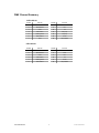
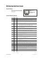
DMX Channel Summary
16- Bi t M o d e
CHANNEL
FUNCTION
CHANNEL
FUNCTION
1
Dimmer
8
Focus
2
Shutter/Strobe
9
Pan
3
Colors
10
Tilt
4
Static Gobos
11
Pan (Fine)
5
Rotating Gobos
12
Tilt (Fine)
6
Gobo Rotation
13
Control
7
Prism
14
Lamp ON/OFF
FUNCTION
CHANNEL
FUNCTION
1
Dimmer
7
Prism
2
Shutter/Strobe
8
Focus
3
Colors
9
Pan
4
Static Gobos
10
Tilt
5
Rotating Gobos
11
Control
6
Gobo Rotation
12
Lamp ON/OFF
8- B it M o d e
CHANNEL
LEG-3000 Manual
5
Revision: 2006-01-20/16:03
Introduction
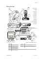
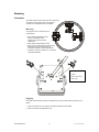
Product Overview
2
2
1. Moving yoke arm
1
2. Projector head
3. Base
4. Carrying handle
5. Fan or Vent
6. LED display
5
7. [Menu] button
4
8. [Menu] button
9. [Down] button
10. [Up] button
11. DMX output
12. DMX input
13. Carrying handle
14. AC input IEC 60320 C14
15. Fuse holder
16. Power switch
See Appendix Section;
Dip Switches (settings explained)
5
3
13
DMX signal indicator
6
11
5
12
15
14
7
8
9
16
10
SEGMENT BUTTONS I/O PANEL OVERVIEW
BUTTONS
I/O PANEL
MENU◄
Toggles Menu Functions
DMX Out & In
DMX-512 connectors
MENU►
Toggles Menu Functions
Power
AC input IEC 60320 C14 and fuse holder
SELECT▼
Steps backwards through
selections or addressing
SELECT▲
Steps forward through
selections or addressing
LEG-3000 Manual
6
Revision: 2006-01-20/16:03
SETUP
Lamp
You will need to install a lamp prior to the initial operation of the fixture. A MSD250 high intensity
discharge lamp is included.
Warning!
When replacing the lamp, please wait 15 minutes after powering down to allow the
unit to cool down! Always disconnect from main power prior to lamp replacement.
Do not touch the envelope (glass area) of the bulb with bare hands. If this happens, clean the lamp
with alcohol and wipe it with a lint free cloth before installation.
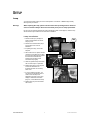
L am p In st a ll at io n
S1
1. Remove screws (S1) and (S2) as
shown in the illustration to remove
lamp top cover.
2. Remove the 2 thumbscrews (S3) to
remove lamp lower cover as
illustrated.
1
3. If replacing the lamp, remove old
lamp first.
4. With a clean cloth or napkin, hold the
new lamp by the glass top end, align
the pins on the lamp with the holes in
the socket and insert the lamp
squarely until the lamp socket
secures the lamp tightly.
S2
2
S3
1
5. Clean the glass/envelope of the bulb
with an alcohol wipe or equivalent.
6. Replace lamp lower cover, align the
screw holes and fasten the
thumbscrews back onto the lamp
lower cover.
7. If you are replacing the lamp, you
may want to log the fixture hours in
order to track the lamps use.
Navigate to the {LPti} on the menu
display to obtain this information.
(Page 11, Control Board Functions)
3,4
8. Replace lamp top cover and fasten
with screws.
LEG-3000 Manual
7
Revision: 2006-01-20/16:03
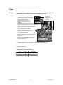
Power
Your product is equipped with an internal input-voltage select switch.
Warning!
Verify that the power select switch on your unit matches the line voltage applied. All
fixtures must be connected to circuits with a suitable Earth Ground.
To determine the power requirements for
cover panel as
a particular fixture, see the label affixed to
illustrated here to gain
the back plate of the fixture or refer to the
access to the switch
shown below.
fixture’s specifications chart.
A fixture’s listed current rating is its
average current draw under normal
conditions.
All fixtures must be powered directly off a
switched circuit and cannot be run off a rheostat (variable
resistor) or dimmer circuit, even if the rheostat or dimmer
channel is used solely for a 0% to 100% switch.
Before applying power to a fixture, check that the
source voltage matches the fixture’s
requirement.
Input Voltage Switch
All fixtures must be connected to circuits
with a suitable Earth Ground.
2
Remove the right base
3
3,4,5
1. Make sure the fixture is not connected to power, if
so disconnect.
2. Remove the right base access cover panel as
illustrated on the right.
3. Locate the power selection switches and dial.
4. Rotate the voltage dial to the setting that most closely matches the local AC voltage. If your
voltage falls halfway between two settings, select the higher voltage on the dial.
5. Move the frequency switch to the setting that matches the local AC frequency; 50 or 60 Hz.
6. Replace access cover.
Po w e r Ca b l e Co nf igu ra t io n
LEG-3000 Manual
CABLE
PIN
BROWN
Live
INTERNATIONAL
L
BLUE
Neutral
N
YELLOW/GREEN
Earth
EG (Ground)
8
Revision: 2006-01-20/16:03
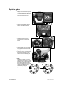
Replacing gobos
1. Begin to remove the fixture top cover
by loosening the screws labeled (S1)
on the lamp heat plate located at the
rear of the head of the fixture.
S1
1
S2
2. Remove the heat plate to expose
reflector and additional screws.
3. Remove screws labeled (S2).
2
S3
4. Rotate the head and remove
screw (S3) from the front of the
fixture.
4
Cover removed
5. Press both tips of the gobo tension
ring together and remove from the
gobo aperture.
6. Push the gobo with your finger from
the back side following the same
direction that the tension ring was
removed.
NOTE!
Replacing the gobos on the static
gobo wheel of the Legend™ 3000X is
achieved using the same method as
the rotating gobo wheel. However,
the spring needs to be removed first
using a small flat head screw
driver before pushing the
gobo out of the aperture.
LEG-3000 Manual
9
5,6
Gobo tension ring
Revision: 2006-01-20/16:03
Mounting
Orientation
All models described in this manual can sit on stage or be
mounted on a truss using a clamp in any position,
provided, there is adequate room for ventilation.
W ar n in g
It is important never to obstruct the fan or
vents pathway.
When selecting installation location,
take into consideration lamp
replacement access and routine
maintenance.
Safety cables should always be used.
Never mount in places where the fixture will be
exposed to rain, high humidity, extreme
temperature changes or restricted ventilation.
The fixture must have a minimum of 1 meter from
combustible materials.
d
a. Clamp brackets
b. Clamps
c. Safety cable channel
a
a
d. Safety cable
Rig g in g
All models described include 2 clamp mounting brackets to which a half-coupler pipe clamp can be
bolted.
1. Verify the structure can hold 10 times the weight of all fixtures to-be installed.
2. Attach two clamps as illustrated above (b).
LEG-3000 Manual
10
Revision: 2006-01-20/16:03
OPERATING INSTRUCTIONS
Control Board
On the control panel you can set the DMX
address, reset the fixture and change fixture
personality trait.
[MENU] Toggles menu
functions.
[SELECT] Changes menu
function status and is used to
set DMX address.
Control Board Functions
FUNCTION
OPTIONS
NOTES
000~512 DMX channel addressing
Lamp use timer
Pressing ▲▼ simultaneously zeroes lamp counter.
Off/On
Off: Normal
On: Shutter closes during the changing of color, gobos
or prism. Shutter will open after color, gobo or
prism is in position.
Off/On
Off: Color wheel gradually advances to the next color
allowing the user to stop between colors.
On: Color wheel will jump to the next color.
Off/On
Off: Normal
On: Focus adjustment
Off/On
Off: Left to right head movement (Pan Normal)
On: Right to left head movement (Pan Inverted)
Off/On
Off/On
Off: 8 bit control mode
On: 16 bit control mode
Off/On
Off: Normal
On: Self-demo
Off/On
Off: Quick paced function demonstration
On: Slow paced function demonstration
Note: Only works with = On
Off/on
Off: Display off, press any key to turn on display
On: Display On
Off/On
Off: Normal
On: Reset all motors at once
Off/On
Off: Normal
On: Reset entire unit, defaults to Off
Off/On
Off/On
Off/On
Off: Lamp Off
On: Lamp On
Off: Normal
On: Reverse LED display
Off: Assign Pan & Tilt’s DMX address to channel 8-1
On: Assign Pan & Tilt’s DMX address to channel 1-4
to zero the timer. Unit: hour
Off/On
Off/On
LEG-3000 Manual
Off: Down to up head movement (Tilt Normal)
On: Up to Down head movement (Tilt Inverted)
Fixture use timer. Press ▼▲ simultaneously for 3 seconds
Off: Normal, please be sure to disconnect DMX console
On: Sound-activated (Slow),see full instructions pg.16
Off: Normal, please be sure to disconnect DMX console
On: Sound-activated (Fast) ,see full instructions pg.16
11
Revision: 2006-01-20/16:03
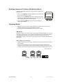
Applying changes to Functions (Quick Instructions)
Unless other wise stated changes in the control board can be applied in the
following manner.
1. Press any of the [MENU] arrow buttons repeatedly until the display reads
the menu function you wish to change.
2. Press any one of the [SELECT] arrow buttons to activate menu function.
The display will show the current state of the function, either “Off” or “On”
with exception for DMX addressing and Lamp Time.
3. Press any one of the [SELECT] arrow buttons again to change the
currently selected setting.
Operating Modes
DMX control mode will provide the greatest flexibility and creativity. Each fixture trait can be
controlled individually using any universal DMX-512 controller.
Stand-alone mode using the optional CA-14 Wired Remote Controller.
DM X M o d e
Operating in a DMX Control mode environment gives the user the greatest flexibility when it comes to
customizing or creating a show. You can tailor your programming to suit a specific event. Whether it
is a wedding where a spot light may be required or a lead singer requiring a color solo, the
opportunities are endless. In this mode you will be able to control each individual trait of the fixture
independently.
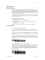
Da is y Ch ai n Co nn e ct i on
1. Connect the (male) 3 pin connector side of the DMX cable to the output (female) 3 pin connector
of the first fixture.
2. Connect the end of the cable coming from the first fixture which will have a (female) 3 pin
connector to the input connector of the next fixture consisting of a (male) 3 pin connector. Then,
proceed to connect from the output as stated above to the input of the following fixture and so on.
Daisy Chain Connection
LEG-3000 Manual
12
Revision: 2006-01-20/16:03
Appendix
Menu Functions
DMX-512 addressing
DMX mode enables the use of a universal DMX controller device. Each fixture requires a "start
address" from 1 to 511. A fixture requiring one or more channels for control begins to read the data
on the channel indicated by the start address. For example, a fixture that occupies or uses 6 channels
of DMX and was addressed to start on DMX channel 100, would read data from channels: 100, 101,
102, 103, 104, and 105. Choose start addresses so that the channels used do not overlap and notate
the start address selected for future reference.
If this is your first time addressing a fixture using the DMX-512 control protocol than I suggest jumping
to the Appendix Section and read the heading “DMX Primer”. It contains very useful information that
will help you understand its use.
S et t i n g t h e s t a rt ing a ddr e ss
1. Press the [MENU] arrow button until the display reads “” .
2. Press the [SELECT] arrow buttons to increase or decrease values until the desired value is
achieved.
3. Press the [MENU] button to activate selection.
Note! Make sure “Aud.S” and “Aud.F” is set to OFF, otherwise it will not allow DMX control.
User Configurations
{ } 8/ 16 b it Cont rol Cha nn el
In the 16 bit Control Channel mode you gain a higher degree of resolution in both Pan and Tilt
movement. One extra channel for both the Pan and the Tilt are added and they perform as the “Fine”
movement.
The primary Pan or Tilt channel is known as the MSB “Most Significant Bit”. This is the channel that
controls the course or broader range of movement. On a DMX signal stream, there are 255 values for
one channel.
The “Fine” Pan or Tilt channel is known as the LSB “Least Significant Bit”. This channel gives you
control of the space between any two MSB values. In other words, it increases the resolution of both
the Pan and Tilt movement, by providing the control of 255 additional values in between each Primary
channel value.
FUNCTION
SET TO
NOTES
Off
On
8 bit Control Channel
16 bit Control Channel
{ } P an r ev e r se / { } T ilt r ev e r se
It is possible to invert the pan and tilt mirror movement from within the fixture itself. This could be
helpful in situations where the positioning or rigging of a fixture led to a reverse orientation of the
fixture in relation to all or most other fixtures installed. When choosing to command the pan or tilt of
all fixtures at the same time you will notice that the fixtures whose orientation is different from the
others will most likely move opposite of the rest. You can apply a pan and tilt Invert by following the
settings in the table below.
FUNCTION
SET TO
Off
On
Off
On
LEG-3000 Manual
NOTES
Left to Right
Right to Left
Down to Up
Up to Down
13
Revision: 2006-01-20/16:03
Appendix
{ } – P an /T ilt co n t ro l ch ann el re- a ss ig n
This function will re-position the pan & tilt control channels to start at DMX value number 1.
FUNCTION
SET TO
On
Off
NOTES
Default
Pan/Tilt re-assign to channel
1-4
{ } - Sh u t t e r aut o - cl os e
The shutter will close momentarily during the color, gobo or prism changes. The shutter will re-open
once the color, gobo or prism has reached its position.
FUNCTION
SET TO
NOTES
Off
On
Normal
Shutter auto-close
{ } - Co lo r w h ee l lin e ar / st e p b eh av io r
This function set to “Off” will allow the linear or gradual progression for the selection of a color on the
color wheel. It gives the user the ability to stop the wheel in between colors. The default “On” setting
advances the color wheel full or complete steps.
FUNCTION
SET TO
Off
On
NOTES
Linear progression
Step advance
{ } – M an u al f o cu s
The user can use this function to manually adjust the focus. This feature can be used in conjunction
with operating the demo show or during maintenance and alignment.
FUNCTION
SET TO
Off
On
NOTES
Normal
Adjust focus
Segment Display Configurations
{ } - Di sp l a y Au t o- of f
The led display can be set to automatically turn off during normal operations.
FUNCTION
SET TO
Off
On
NOTES
Display Auto-Off, press any
key to turn on display
Always on
{ } - R ev e r se t h e dis pl a y
You can rotate the display 180° so that it becomes easier to read when the fixture is positioned
upside down.
FUNCTION
LEG-3000 Manual
SET TO
NOTES
Off
On
Normal display view
Reverse the display
14
Revision: 2006-01-20/16:03
Appendix
Service Functions
{ } - F i xt u r e R es e t ( a ll mo t o rs)
This function will re-initialize the fixture by returning all motors to its startup positions or otherwise
known as (home position).
FUNCTION
SET TO
NOTES
Off
On
Normal
Reset all motors
{ } - F i xt u r e Re s et ( e xc lud e s P an & T ilt )
This function will re-initialize the fixture with exception of the Pan and Tilt motors.
FUNCTION
SET TO
NOTES
Off
On
Normal
Reset unit
{ } – L am p T im e
The (lamp time) readout displays the number of hours the lamp has been in use. It is not uncommon
to find new fixtures with a few logged hours. This means the fixture was thoroughly tested prior to
delivery.
1. Press the [◄ MENU] button until the display reads “”.
2. Press [▼SELECT] button to read the number of hours used.
3. Press both [▼▲ SELECT] buttons at the same time to reset the lamp counter to zero if changing
a lamp.
{ } – F i xt u re T im er
The (Fixture Timer) readout displays the total number of operating hours of the fixture. It is not
uncommon to find new fixtures with a few logged hours.
LEG-3000 Manual
15
Revision: 2006-01-20/16:03
Appendix
Self Demonstration & Master/Slave
{ } – S elf - d e mo
This function will execute the built-in program in the fixture.
FUNCTION
SET TO
NOTES
Off
On
Normal
Run self-demonstration
{ } – De mo s pe ed
You can set the pace of the demo to either quick or fast.
FUNCTION
SET TO
NOTES
Off
On
Quick paced
Slow paced
{ } – So u n d - Ac t i v e ( M ast e r/ S lav e)
In this mode the fixture can be set to run in a sound-activated mode in either a fast or slow pace.
Additionally, slave fixtures can all also be set to synchronize to the first fixture or in this case Master.
Please disconnect from the controller before enabling this function.
Requirements:
In the Legend 3000X the default 16-bit channel mode is required to be set. The Legend 3000X is
controlled using 14 channels.
FUNCTION
SET TO
Off
On
Normal “Off”
Sound-active slow pace
FUNCTION
SET TO
NOTES
Off
On
NOTES
Normal “Off”
Sound-active fast pace
M ast e r F i xt u re Se t t in gs
1.
2.
DMX address Ch 001
Set Aud.S or Aud.F to “On”
Sl av e F ixt u r e Set t ing s
In a Master/Slave setup all slave fixtures following the master would be addressed the same. Please
follow the following instructions for all slave fixtures.
Legend 2000X: DMX address Ch 014, Aud.S or Aud.F set to OFF
Legend 3000X: DMX address Ch 015, Aud.S or Aud.F set to OFF
Important!
All Slave fixtures must have “Aud.S” or “Aud.F” set to off.
You must set “Aud.S” and “Aud.F” to off to regain DMX control of the fixture.
LEG-3000 Manual
16
Revision: 2006-01-20/16:03
APPENDIX
DMX Primer
There are 512 channels in a DMX-512 connection. Channels may be assigned in any manner. A
fixture capable of receiving DMX-512 will require one or a number of sequential channels. The user
must assign a starting address on the fixture that indicates the first channel reserved in the controller.
There are many different types of DMX controllable fixtures and they all may vary in the total number
of channels required. Choosing a start address should be planned in advance. Channels should
never overlap. If they do, this will result in erratic operation of the fixtures whose starting address is
set incorrectly. You can however, control multiple fixtures of the same type using the same starting
address as long as the intended result is that of unison movement or operation. In other words, the
fixtures will be slaved together and all respond exactly the same.
DMX fixtures are designed to receive data through a serial Daisy Chain. A Daisy Chain connection is
where the DATA OUT of one fixture connects to the DATA IN of the next fixture. The order in which
the fixtures are connected is not important and has no effect on how a controller communicates to
each fixture. Use an order that provides for the easiest and most direct cabling. Connect fixtures
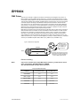
using shielded two conductor twisted pair cable with three pin XLR male to female connectors. The
shield connection is pin 1, while pin 2 is Data Negative (S-) and pin 3 is Data positive (S+). CHAUVET
carries 3-pin XLR DMX compliant cables, DMX-10 (33’), DMX-4.5 (15’) and DMX-1.5 (5’)
Figure 1 - DMX connector configuration
1
3
2
COMMON
INPUT
1
3
1
3
DMX +
2
2
DMX -
Resistance 120
ohm 1/4w between
pin 2 (DMX -) and
pin 3 (DMX +) of
the last fixture.
OUTPUT
Termination reduces signal errors and to
avoid signal transmission problems and
interference, it is always advisable to
connect a DMX signal terminator.
F ix t u re L i n k in g
Note!
If you use a controller with a 5 pin DMX output connector, you will need to use a 5
pin to 3 pin adapter. CHAUVET Model No: DMX5M.
The chart below details a proper cable conversion:
3 PIN TO 5 PIN CONVERSION CHART
LEG-3000 Manual
Conductor
3 Pin Female (output)
5 Pin Male (Input)
Ground/Shield
Pin 1
Pin 1
Data ( - )signal
Pin 2
Pin 2
Data ( + ) signal
Pin 3
Pin 3
Do not use
Do not use
Do not use
Do not use
17
Revision: 2006-01-20/16:03
Appendix
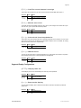
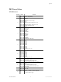
DMX Channel Values
16 Bit Movement
CHANNEL
VALUE
FUNCTION
1
000 255
Dimmer
Closed > Open (0-100%)
2
000 001
002 007
008 063
064 071
072 127
128 135
136 191
192 199
200 253
254 255
Shutter/Strobe
Blackout
Open
Strobe: Slow > Fast (max 7fps)
Open
Pulse Strobe: Dark > Bright & Slow > Fast
Open
Pulse Strobe: Bright > Dark & Slow > Fast
Open
Random Strobe: Slow > Fast
Open
3
000 013
014 027
028 041
042 055
056 069
070 083
084 097
098 111
112 125
126 139
140 153
154 167
168 255
Color Wheel
White (Open)
Steel Blue
Orange
Green Blue
Bright Blue
Bright Pink
Red
Deep Blue
Yellow
Dark Pink
Moss Green
Light Blue
Rainbow effect: Slow > Fast
4
000 015
016 031
032 047
048 063
064 079
080 095
096 111
112 127
128 143
144 159
160 255
Fixed Gobo Wheel
Open
Gobo 1
Gobo 2
Gobo 3
Gobo 4
Gobo 5
Gobo 6
Gobo 7
Gobo 8
Gobo 9
Gobo Spin: Slow > Fast
5
000 023
024 047
048 071
072 095
096 119
120 143
144 167
168 255
Rotating Gobo
Open
Gobo 1
Gobo 2
Gobo 3
Gobo 4
Gobo 5
Gobo 6
Gobo Spin: Slow > Fast
5
000 127
128 191
192 255
Gobo Rotation & Indexing
Gobo Index (0° ~ 360°)
Clockwise gobo rotation: Slow > Fast
Counter clockwise gobo rotation: Fast > Slow
6
000 001
002 007
008 131
132 253
254 255
Prism
Open
Prism (static)
Prism clockwise rotation: Slow > Fast
Prism counter-clockwise rotation: Fast > Slow
Prism (static)
8
000 255
Focus
Near > Far
000 255
Pan
Right (0°) > Left (570°) ( 128 = half way point)
9
Continued on the next page…
LEG-3000 Manual
18
Revision: 2006-01-20/16:03
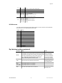
Appendix
10
11
000 255
000 255
Tilt
Down (0°) > Up (270°) (128 = half way point)
Pan (Fine)
12
000 255
Tilt (Fine)
13
000 007
008 063
064 127
128 255
Control
Pan/Tilt Tracking Mode
Pan/Tilt Vector Mode: Slow > Fast
Reserved
Mechanical reset after 3 seconds
14
000 047
048 095
096 159
160 207
208 255
Lamp ON/OFF
Standby
Hold 3 seconds for Lamp ON
Standby
Hold 3 seconds for Lamp OFF
Standby
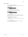
8 Bit Movement
In the 8 bit Pan/Tilt resolution setting both (FINE) channels is removed. All other channel parameters
remain the same as in the “DMX Channel Values” table.
CHANNEL
FUNCTION
1
Dimmer
2
Shutter
3
Color
4
Static Gobo
5
Rotating Gobo
6
Gobo Rotation
7
Prism
8
Focus
9
Pan
10
Tilt
11
Control
12
Lamp ON/OFF
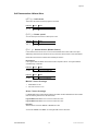
Dip Switches (settings explained)
LEG-3000 Manual
DIP SWITCH
EVENT
NOTES
All Off
The lamp will strike first. If striking of the lamp succeeds, in
approximately 15 seconds the fixture’s motors will be powered
and initialized. If the lamp does not strike, the remainder of the
fixture will not initialize and you will not have control of the
fixture. Please wait 15 minutes before re-starting the
fixture, otherwise perform a service check.
This is the default
setting on the fixture
and helps in reducing
the amount of striking or
inrush current used by
the fixture upon startup.
1-On
Lamp and motors are powered at the same time.
Will consume the most
amount of inrush current
in the startup phase.
2-On
Only the lamp will turn on in the fixture.
1-On, 2-On
Only the lamp will turn on in the fixture
3-On
This switch will terminate the dmx connection.
19
Use only at the end of a
DMX daisy chain.
Revision: 2006-01-20/16:03
Appendix
Maintenance
To maintain optimum performance and minimize wear fixtures should be cleaned frequently. Usage
and environment are contributing factors in determining frequency. As a general rule, fixtures should
be cleaned at least twice a month. Dust build up reduces light output performance and can cause
overheating. This can lead to reduced lamp life and increased mechanical wear. Be sure to power off
fixture before conducting maintenance.
Unplug fixture from power. Use a vacuum or air compressor and a soft brush to remove dust
collected on external vents and internal components. Clean all glass when the fixture is cold with a
mild solution of glass cleaner or Isopropyl Alcohol and a soft lint free cotton cloth or lens tissue. Apply
solution to the cloth or tissue and drag dirt and grime to the outside of the lens. Gently polish optical
surfaces until they are free of haze and lint. Do not to touch the lamp glass when cleaning fixture. Oil
and dirt can cause damage and premature aging of the lamp. In the event that the lamp is touched or
becomes dirty, clean the lamps with an alcohol wipe.
The cleaning of internal and external optical lenses and/or mirrors must be carried out periodically to
optimize light output. Cleaning frequency depends on the environment in which the fixture operates:
damp, smoky or particularly dirty surrounding can cause greater accumulation of dirt on the unit’s
optics. Clean with soft cloth using normal glass cleaning fluid. - Always dry the parts carefully. - Clean
the external optics at least every 20 days. Clean the internal optics at least every 30/60 days.
Returns Procedure
Returned merchandise must be sent prepaid and in the original packing, call tags will not be issued.
Package must be clearly labeled with a Return Merchandise Authorization Number (RA #). Products
returned without an RA # will be refused. Call CHAUVET and request RA # prior to shipping the
fixture. Be prepared to provide the model number, serial number and a brief description of the cause
for the return. Be sure to properly pack fixture, any shipping damage resulting from inadequate
packaging is the customer’s responsibility. CHAUVET reserves the right to use its own discretion to
repair or replace product(s). As a suggestion, proper UPS packing or double-boxing is always a safe
method to use.
Claims
Damage incurred in shipping is the responsibility of the shipper; therefore the damage must be
reported to the carrier upon receipt of merchandise. It is the customer's responsibility to notify and
submit claims with the shipper in the event that a fixture is damaged due to shipping. Any other claim
for items such as missing component/part, damage not related to shipping, and concealed damage,
must be made within seven (7) days of receiving merchandise.
LEG-3000 Manual
20
Revision: 2006-01-20/16:03
Appendix
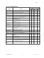
General Troubleshooting
Applies to
Symptom
Solution(s)
Lights
Controllers
Dimmers
& Chaser
Auto shut off
Check fan thermal switch reset
Beam is very dim or not
bright
Clean optical system or replace lamp
Check 220/110v switch for proper setting
Breaker/Fuse keeps
blowing
Check total load placed on device
Chase is too slow
Check users manual for speed adjustment
Device has no power
Check for power on Mains.
Check device’s fuse. (internal and/or external)
Fixture is not responding Check DMX Dip switch settings for correct addressing
Check DMX cables
Check polarity switch settings
Fixture is on but there is
no movement to the
audio
Make sure you have the correct audio mode on the control
switches. If audio provided via ¼” jack, make sure a live audio
signal exists
Adjust sound sensitivity knob
Lamps cuts off
sporadically
Possible bad lamp or fixture is overheating.
Lamp may be at end of its life.
Light will not come on
after power failure
Some discharge lamps require a cooling off period before the
electronics in the fixture can kick start it again, wait 5 to 10
minutes before powering up
Loss of signal
Use only DMX cables
Install terminator
Note: Keep DMX cables separated from power cables or black
lights.
Motor movements are
jerky or jumpy
Possible bad motor driver or sensors
Check polarity switch on controller
Moves slow
Check 220/110v switch for proper setting
No flash
Re-install bulb, may have shifted in shipping
No light output
Check slip ring & brushes for contact
Install bulb
Call service technician
Relay will not work
Check reset switch
Check cable connections
Remote does not work
Make sure connector is firmly connected to device
Stand alone mode
All CHAUVET lighting fixtures featuring stand-alone functions
do not require additional settings, simply power the fixture and
it will automatically enter into this mode
Unit wobbles when
rotating
Check for damages possibly incurred during shipping
LEG-3000 Manual
Foggers
& Snow
21
Revision: 2006-01-20/16:03
Appendix
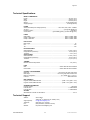
Technical Specifications
WEIGHT & DIMENSIONS
Length........................................................................................................................... 381 mm (15 in)
Width............................................................................................................................. 406 mm (16 in)
Height ........................................................................................................................... 635 mm (25 in)
Weight................................................................................................................... 27.44 Kgs (60.5 lbs)
Shipping Weight....................................................................................................... 30.84 Kgs (68 lbs)
POWER
Switch-selectable power settings (Internal).................................... 115V, 220V, 230V, 240V – 50/60Hz
AC input .........................................................................................................3 prongs IEC 60320 C14
European Version ............................................................................................................... 230V/240V
Current draw ................................................................. (peak 388W @ 120V), (inrush 678W @ 120V)
LAMPS
HSD-250/80 ...................................................................................................... 3000 hr, 8000K, 250W
Philips™ MSD-250/2......................................................................................... 2000 hr, 6500K, 250W
Philips™ MSD-200............................................................................................ 2000 hr, 5600K, 200W
PHOTO OPTIC
Beam Angle .................................................................................................................................... 15°
Pan ............................................................................................................................................... 570°
Tilt................................................................................................................................................. 270°
ROTATING GOBOS
Outside diameter.......................................................................................................... 31 mm (1.22 in)
Image diameter (maximum)............................................................................................24 mm (.94 in)
Thickness.........................................................................................................................3 mm (.12 in)
STATIC GOBOS
Outside diameter.......................................................................................................... 31 mm (1.22 in)
Image diameter (maximum)............................................................................................24 mm (.94 in)
Thickness......................................................................................................................(.2) mm (.01 in)
THERMAL
Maximum ambient temperature ......................................................................................... 40° (104° F)
FUSE
Main ................................................................................................... 20mm Glass 8A 250V Fast Blow
Internal PCB....................................................................................... 20mm Glass 5A 250V Fast Blow
CONTROL & PROGRAMMING
Data input ...................................................................................... non-locking 3-pin XLR male socket
Data output ................................................................................. non-locking 3-pin XLR female socket
Data pin configuration ............................................................................pin 1 shield, pin 2 (-), pin 3 (+)
Protocols.....................................................................................................................DMX-512 USITT
DMX CHANNELS
Legend™ 2000X, DMX Channels ............................................................. (16bit = 13ch), (8bit = 11ch)
Legend™ 3000X, DMX Channels.............................................................. (16bit = 14ch), (8bit = 12ch)
ORDERING INFORMATION
Legend™ 3000X ...................................................................................................................LEG-3000
Fuse 8A 250V ............................................................................................................... P170FUSE008
Fuse 5A 250V ............................................................................................................... P170FUSE005
OPTIONS
Wired Remote Controller for stand-alone ....................................................................................CA-14
Technical Support
Address:
Support (Email):
Telephone:
Fax:
Website:
LEG-3000 Manual
Service Dept.
3000 N 29th Ct, Hollywood, FL 33020 (U.S.A.)
[email protected]
(954) 929-1115 - (Press 4)
(954) 929-5560 - (Attention: Service)
http://www.chauvetlighting.com
22
Revision: 2006-01-20/16:03