1
Pilot’s Guide
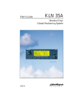
KLX 135
Bendix/King®
GPS/COMM
ORS 01
A
AlliedSignal General Aviation Avionics
400 North Rogers Road
Olathe, Kansas 66062-1212
TELEX 669916 KINGRAD • FAX 913-791-1302
TELEPHONE (913) 768-3000
© 1994 AlliedSignal Inc.
6/95 006-08751-0000
1K
Printed in USA
A
KLX 135 Pilot’s Guide
INTRODUCTION
Table of Contents
.........................................................................i
KLX 135 SNEAK PREVIEW ..........................................................ii
HOW-TO INDEX
.......................................................................iv
1. KLX 135 SYSTEM COMPONENTS .......................................1-1
2. DATA BASE
.....................................................................2-1
2.1. Data Basics .......................................................................2-1
2.2. Data Base Contents and Coverage Areas .......................2-1
2.3. ICAO Identifiers .................................................................2-3
2.4. Updating the Data Base ....................................................2-3
2.5. User Defined Data Base ...................................................2-6
2.6. Data Base Update Service Options ..................................2-7
3. COMM OPERATION ..............................................................3-1
3.1. Entering Frequencies ........................................................3-1
3.1.1. Frequency Selection ................................................3-1
3.1.2. Standby Frequency Entry ........................................3-1
3.1.3. Active Frequency Entry ...........................................3-2
3.1.4. 25 Kilohertz Channel Spacing Operation ................3-2
3.1.5. Using QuickTune™ Frequency Selection ...............3-3
3.2. Receive/Transmit Annunciation ........................................3-4
3.3. Volume Adjustment and Automatic Squelchb Override ...3-4
3.4. Stuck Microphone Protection ............................................3-4
3.5 Blind Tuning Feature ..........................................................3-5
4. BASIC GPS OPERATION ......................................................4-1
4.1. Coverage Area ..................................................................4-1
4.2. Turn-on and Self Test .......................................................4-1
4.3. Display Format ..................................................................4-7
4.4. Basic Operation of Panel Controls ....................................4-9
4.4.1. Page Selection ......................................................4-10
4.4.2. Data Entry ..............................................................4-11
4.4.3. The Duplicate Waypoint Page ..............................4-14
4.4.4. Cyclic Fields ..........................................................4-15
4.5. Message Page ................................................................4-16
4.6. Initialization and Time to First Fix ...................................4-17
4.7. Selecting and Scanning Waypoints ................................4-20
4.7.1. Selecting Waypoints by Identifier ..........................4-20
4.7.2. Selecting Waypoints by Scanning .........................4-22
4.7.3. “Nearest” and “Complete” Waypoint Scan Lists ...4-23
4.7.4. Selecting Waypoints by Name or City ..................4-25
006-08751-0000 Rev 0
Effective Date 3/94
Table of Contents
4.8. Direct to Operation ..........................................................4-28
4.8.1. Initiating a Direct To ..............................................4-28
4.8.2. Canceling a Direct To ............................................4-30
4.8.3. Waypoint Alerting for Direct To Operation ............4-31
4.9. Creating and Modifying Flight Plans ...............................4-31
4.9.1. Creating a Flight Plan ............................................4-32
4.9.2. Viewing Distance and Desired Track Between
Stored Flight Plan Waypoints ............................4-34
4.9.3. Activating a Numbered Flight Plan ........................4-34
4.9.4. Adding a Waypoint to a Flight Plan .......................4-35
4.9.5. Deleting a Waypoint from a Flight Plan ................4-36
4.9.6. Deleting Flight Plans .............................................4-37
4.9.7. Storing FPL 0 as a Numbered Flight Plan ............4-37
4.10. Operating from the Active Flight Plan ...........................4-38
4.10.1. General Procedures ............................................4-38
4.10.2. Turn Anticipation and Waypoint Alerting .............4-39
4.10.3. Viewing the Waypoint Pages for the
Active Flight Plan Waypoints .............................4-41
4.10.4. Combining Direct To and Flight Plan Operation .4-41
4.10.5. Viewing Distance, ETE, ETA, or Desired
Track to Flight Plan Waypoints ..........................4-43
4.11. Navigation Pages ..........................................................4-44
4.11.1. The Navigation 1 (NAV 1) Page ..........................4-44
4.11.2. The Navigation 2 (NAV 2) Page ..........................4-47
4.11.3. The Navigation 3 (NAV 3) Page ..........................4-48
4.11.4. The Navigation 4 (NAV 4) Page ..........................4-48
4.12. Waypoint Pages ............................................................4-49
4.12.1. Airport Pages .......................................................4-49
4.12.1.2. The Airport 2 (APT 2) Page .............................4-50
4.12.1.3. The Airport 3 (APT 3) Page .............................4-51
4.12.1.4. The Airport 4 (APT 4) Page ............................4-52
4.12.2. VOR Pages .........................................................4-53
4.12.3. NDB Pages ..........................................................4-54
4.12.4. Supplemental Waypoint Pages ...........................4-55
4.13. Viewing and Setting the Date and Time .......................4-58
4.14. The Other (OTH) Pages ...............................................4-60
4.14.1. Determining the Status of the GPS Signals ........4-60
4.14.2. Viewing and Deleting User Waypoints and
Waypoint Remarks ............................................4-62
4.14.3. Viewing the KLX 135 Software Status and
Time of Operation ..............................................4-64
4.15. Remote Mounted Annunciators ....................................4-64
Effective Date 3/94
006-08751-0000 Rev 0
KLX 135 Pilot’s Guide
Table of Contents
5. ADVANCED GPS OPERATION .............................................5-1
5.1. Calculator Pages ...............................................................5-1
5.1.1. The Calculator (CAL) 1 Page ..................................5-1
5.1.2. The Calculator (CAL) 2 Page ..................................5-3
5.2. Creating User-defined Waypoints ....................................5-5
5.2.1. Creating a Waypoint at Your Present Position .......5-5
5.2.2. Creating a Waypoint at a Certain Latitude/
Longitude .............................................................5-6
5.2.3. Creating a Waypoint Referenced from
Another Waypoint ................................................5-8
5.3. Navigation Modes .............................................................5-9
5.3.1. Selecting the Leg Mode or the OBS mode ...........5-10
5.3.2. The En route-Leg Mode ........................................5-10
5.3.3. The En route-OBS Mode ......................................5-11
5.3.4. Effects of Switching From En route-OBS
Mode to En route-Leg Mode ..............................5-11
5.3.5. Activating a Waypoint While in the
En route-OBS Mode ..........................................5-12
5.4. Operation Outside the Primary Coverage Area ..............5-13
5.5. Using the Take-home Mode ...........................................5-14
APPENDIX A - NAVIGATION TERMS ......................................A-1
APPENDIX B - MESSAGE PAGE MESSAGES ........................B-1
APPENDIX C - SCRATCHPAD MESSAGES ............................C-1
APPENDIX D - ABBREVIATIONS .............................................D-1
STATE ABBREVIATIONS .......................................................D-1
CANADIAN PROVINCE ABBREVIATIONS ...........................D-2
COUNTRY ABBREVIATIONS ................................................D-2
OTHER ABBREVIATIONS USED ON KLX 135 PAGES .......D-8
APPENDIX E - LAT/LON CONVERSIONS ................................E-1
006-08751-0000 Rev 0
Effective Date 6/95
Table of Contents
This page intentionally left blank
Effective Date 3/94
006-08751-0000 Rev 0
KLX 135 Pilot’s Guide
Introduction
INTRODUCTION
Welcome to the world of GPS flying! Your Bendix/King KLX 135
GPS/COMM is sure to make your flying more efficient and more fun.
After all, isn't that why you got into flying in the first place? Now when
you're flying VFR, you probably won't need to be constantly figuring
or looking up VOR radials and distances.
The convenient QuickTune™ feature will allow you to easily look up
the frequency for the appropriate airport, then transfer it to the
KLX 135 COMM transceiver.
This Pilot's Guide should be of great help to you. It is written in plain,
simple English and it assumes you are not an experienced user of
GPS or other type of long range navigation equipment. If you are
experienced, so much the better. This Pilot's Guide also includes
hundreds of sample screen figures and other illustrations to make
your learning easier. It is designed so that you can start at the front
and progress in the order presented; however, you may want to skip
around and learn things in your own order. Also, on page iv, there is
an index of frequently used procedures which will help you find the
page that describes how to do exactly what you want to do. There
are also several appendices in the back of the manual that you may
find useful from time to time.
Be sure to keep this Pilot's Guide handy with you in the airplane. It is
designed to fit easily in the glove box, or in the seat pocket. The
KLX 135 is very simple to operate, but the Pilot's Guide can sure be
of help to you.
One last thing. Don't get so involved in learning to use the KLX 135
that you forget to fly the airplane. Be careful, and remember to keep
a close eye out for other aircraft.
NOTE: A “whiskers” border is used around
data on some of the figures in this Pilot's Guide
to indicate that the data inside the border is
flashing.
006-08751-0000 Rev 0
i
122.90
ZBV
123.12 BIMINI
#>Leg
N 2
VOR 1
W 7
Effective Date 3/94
Introduction
KLX 135 SNEAK PREVIEW
If you absolutely can't wait to use your KLX 135 until you've read this
Pilot's Guide, this section is for you. This page will teach you just
enough to get going and then learn by doing. This operational preview assumes the KLX 135 has been properly installed, the unit was
previously operational in the same general geographical location, and
that no peripheral equipment interfaced with the KLX 135 (such as
external HSIs, CDIs, autopilots, moving map display, etc.) is to be
used at this time. If you are using this operational preview in flight, do
so only in good VFR conditions and only with an alternate means of
navigation (including pilotage) available to cross-check position.
1. Turn the unit on with the On/Off/Volume knob (the small knob in
upper left hand corner). Adjust the COMM audio volume as
desired by pulling this knob out, turning it to an appropriate level
and pushing it back in.
2. For a few seconds, the Turn On Page is displayed while the unit
runs a self-test. Afterwards, the Self-test Page is displayed. If
the KLX 135 is receiving an altitude from an encoding altimeter,
the present pressure altitude will be displayed on line 3. The bottom line should display Self-test Pass and a flashing Ok?.
Press the F button to approve the Self-test Page.
3. The Initialization Page will now be displayed. If the date and time
are incorrect by more than 10 minutes, refer to section 4.2 of this
Pilot's Guide. The right side of the screen should show the
identifier of the nearest airport to the initial position, along with a
radial and distance from that airport waypoint. Press F with
the cursor flashing over Ok? to approve the Initialization Page.
4. The VFR page will now be displayed to notify you that the GPS is
for VFR use only. Press F to approve this page.
5. A Data Base Page is now displayed showing the date the data
base expires or the date it expired. Press F to acknowledge
the information displayed on this page.
Effective Date 3/94
ii
006-08751-0000 Rev 0
KLX 135 Pilot’s Guide
Introduction
6. The next page displayed will probably be a page showing the
VHF communication frequencies for the airport you are at. For
now, use the right outer knob to turn to the NAV page type
(watch the lower left corner of the screen and the small bar at the
bottom to know when you are there). Then use the right inner
knob to select the NAV 2 page if not already there. The NAV 2
page shows your present position relative to a nearby VOR.
Verify that this position is correct before proceeding.
7. Press the D button. A page with the words DIRECT TO is now
displayed on the screen.
In step 8 you will enter the ICAO identifier of the airport. The
identifier will have a "K" prefix for a Continental U.S. airport, a "C"
prefix for a Canadian airport, or a "P" prefix (in some cases) for
an Alaskan airport if the identifier is all letters. For example, LAX
becomes KLAX. For these countries if the identifier contains any
numbers, there is no prefix. For example, TX04 is entered TX04.
For other areas of the world the airport identifier should be
entered identically to how it is charted.
8. Rotate the right inner knob until the first character of the airport
identifier is displayed. Turn the right outer knob one step clockwise to move the flashing segment to the second character
position. Rotate the right inner knob to select the second character of the identifier. Use this procedure to enter the complete
airport identifier.
9. Press F. The display will change to a page showing the identifier, name, city, and state/country of the airport just entered.
Confirm that the correct airport is displayed. Press F a second
time to approve the airport data.
10. A Navigation page is now on the screen. It displays the distance,
groundspeed, bearing, and ETE to the destination airport. In
addition, it displays a course deviation indicator (CDI).
See--wasn't that easy?
006-08751-0000 Rev 0
iii
Effective Date 3/94
Introduction
HOW-TO INDEX
This index will help you quickly find important procedures at a glance.
The list is alphabetized by action words.
TO:
SEE PAGE:
Activate a waypoint in OBS mode without changing the
selected course ................................................................................5-12
Activate one of the previously created numbered flight plans ............4-34
Add a waypoint to a flight plan ............................................................4-35
Calculate distance and time for a flight plan .........................................5-2
Calculate distance, bearing, and time from waypoint to waypoint........5-1
Calculate fuel requirements for a flight plan..........................................5-4
Calculate fuel requirements from waypoint to waypoint .......................5-3
Cancel Direct To operation .................................................................4-30
Change a cyclic field ...........................................................................4-15
Change navigation modes ..................................................................5-10
Change the default first waypoint character........................................4-13
Change the NAV 2 page present position reference waypoint...........4-47
Create a flight plan ..............................................................................4-32
Create a user-defined waypoint at your present position .....................5-5
Create a user-defined waypoint using the radial/distance method.......5-8
Create a user-defined waypoint with latitude/longitude ........................5-6
Cycle between distance and desired track display on a
numbered flight plan page ...............................................................4-34
Cycle between distance, ETE, ETA, and desired track on the
FPL 0 page.......................................................................................4-43
Delete a flight plan which is no longer required ..................................4-37
Delete a user-defined waypoint from the OTH 3 page .......................4-62
Delete a waypoint from a flight plan ....................................................4-36
Delete a waypoint remark from the OTH 4 page ................................4-63
Display the nearest airport continuously..........................................4-24
Display the nearest airports in an emergency ....................................4-24
Effective Date 6/95
iv
006-08751-0000 Rev 1
KLX 135 Pilot’s Guide
Introduction
TO:
SEE PAGE:
Enter a user-defined waypoint remark on the SUP 3 page ................4-57
Enter a waypoint identifier ...................................................................4-12
Enter an airport remark on the APT 3 page ........................................4-51
Enter the local magnetic variation manually on the SET 2 page ........5-14
Fly Direct To a waypoint......................................................................4-28
Fly direct to a waypoint in the active flight plan (FPL 0) .....................4-42
Initialize the position from the SET 1 page .........................................4-18
Recenter the D-Bar by going direct to the active waypoint.................4-30
Select a VOR or NDB by navaid name ...............................................4-25
Select a waypoint by identifier from a waypoint page.........................4-20
Select a waypoint by scanning with the cursor off ..............................4-22
Select a waypoint by scanning with the cursor on ..............................4-22
Select an airport by scanning the airport name ..................................4-26
Set the date on the SET 2 page..........................................................4-58
Set the time on the SET 2 page ..........................................................4-59
Store the active flight plan as a numbered flight plan .........................4-37
Tune a COMM frequency......................................................................3-1
Tune a COMM frequency from the data base ......................................3-3
Tune a COMM frequency using the active frequency
entry mode .........................................................................................3-2
Tune a COMM frequency using the standby frequency
entry mode .........................................................................................3-1
Tune a 25 kHz COMM frequency .........................................................3-2
Turn on and initialize the KLX 135 ........................................................4-2
Update the KLX 135 data base .............................................................2-3
View a message ..................................................................................4-16
View the Nearest airports, VORs, or NDBs ........................................4-24
View the waypoints in the flight plan that are not the
active waypoint.................................................................................4-41
006-08751-0000 Rev 0
v
Effective Date 3/94
REQUIRED
OPTIONAL
HSI
GS
3
W
W
24
24
15
S
21
21
S
118®00
∂∆ KOSH
136.97 > ««««∑∏π««««
>Leg
89.6nm
105kt
NAV 1
>345°To
0:51
APT VOR NDB SUP ACT NAV FPL CAL SET OTH
MSG
D
CLR
ENT
AUTOPILOT
YD
CRSR
ALT HDG
GS
NAV
APR
NAV
APR
AP
BC
DN
KC 193
GPS
UP
ALT
ı
Pull
SCAN
RN
HDG
RC
BC
PC
TEST
AP
ENG
1-0
Pull
25k
KI 206
KLX 135
Pull
TEST
COMM
12
12
FR
ı
KI 525A
VOL
OFF
TO
E
E
OBS
ALTITUDE GRAY CODE
3
N
A
V
GS
ı
B
N
6
OR
GS
30
33
33
6
AIRCRAFT 14V
POWER
CDI
HDG
N
30
NAV
15
COMM
ANTENNA
GPS ANTENNA
006-08751-0000 Rev 0
KLX 135 SYSTEM
REMOTE ANNUNCIATORS
WPT ALERT
MESSAGE
MOVING MAP
DISPLAYS
MKR
A
SPEAKER
T
S
T
HI
O
M
LO
S
E
N
S
TEL
1 COM 2
1 NAV 2
DME
PHONE
MKR
COM 1 COM 2
HF
INT
OFF
EXT
ADF AUTO
MIC KMA 24 TSO
AUDIO PANEL
OR
AND/
OR
SPEAKER
HEADPHONES
ARTEX
ELS-10
Effective Date 3/94
RS-232
OUTPUT
AUDIO
MIC
System Components
Chapter 1
System Components
MIC KEY
KLX 135 Pilot’s Guide
System Components
A basic KLX 135 system consists of a panel mounted KLX 135
GPS/COMM and a GPS antenna. An altitude input is required to
obtain full navigation and operational capabilities. Additional system
components may be added or interfaced to the KLX 135 which
increase its features and capabilities. Some of these optional components include an external course deviation indicator (CDI) or
horizontal situation indicator (HSI), ARTEX ELS-10 emergency locator transmitter (ELT), autopilot, and external annunciators.
The KLX 135 panel mounted unit contains the GPS sensor, the navigation computer, a COMM transceiver, a liquid crystal display (LCD),
and all controls required to operate the unit.
Installation of an appropriate VHF communication antenna (capable
of receiving 118.000 to 136.975 MHz) is required. However, the VHF
COMM antenna is not included as part of the KLX 135 system.
The GPS “patch” antenna is available for use with the KLX 135. It is
designed to always be mounted on the top of the aircraft.
The KLX 135 has analog outputs to drive the left-right deviation bar of
most mechanical CDIs and HSIs. In addition, the NAV mode of the
Bendix/King KFC 150, KAP 150, KAP 150H, KAP 100, KFC 200,
KAP 200, KFC 250, KFC 275, KFC 300, and KFC 325 flight control
systems may be coupled to the KLX 135. Many other autopilots may
also be coupled to the KLX 135. Actual autopilot performance and
capability when coupled to the KLX 135 may vary significantly from
one autopilot model to another.
Altitude may be provided to the KLX 135 from an encoding altimeter
or blind encoder. Altitude is used as an aid in position determination
when not enough satellites are in view.
Some installations may require remote annunciators to be mounted
in the aircraft panel in order to indicate the status of certain KLX 135
functions, namely waypoint alert and message.
006-08751-0000 Rev 0
1-1
Effective Date 3/94
System Components
Chapter 1
1. KLX 135 SYSTEM COMPONENTS
45°
45°
USA
30°
15°
30°
MID EAST
PACIFIC
PACIFIC
LATIN AM
0°
15°
0°
AFRICA
15°
15°
SOUTH AM
30°
45°
30°
SOUTH PAC
SOUTH PAC
60°
165°150° 135° 120°105° 90° 75° 60° 45° 30° 15° 0° 15° 30° 45° 60° 75° 90° 105° 120°135° 150° 165°180°
North American Data Base primary area
Data Base
Chapter 2
Data Base
60°
45°
International Data Base primary area
006-08751-0000 Rev 0
60°
EAST EUR
CANADA
2-0
EUROPE
60°
Figure 2-1 KLX 135 Data Base Geographical Region
75°
Effective Date 3/94
75°
KLX 135 Pilot’s Guide
Data Base
2. DATA BASE
2.1. DATA BASICS
The second function of the data base is that it serves as a very convenient means to store and easily access aeronautical information.
Want to know the name of the airport, the nearest city, or the airport
altitude? Just unleash the power of the KLX 135 and display the
information right on the screen.
2.2. DATA BASE CONTENTS AND COVERAGE AREAS
There are two data base coverage areas available for the KLX 135.
One is referred to as the “North American” data base and the other is
referred to as the “International” data base.
The International Civil Aviation Organization (ICAO) and Aeronautical
Radio, Inc. (ARINC) break the world into the ten geographic regions
shown in figure 2-1. The KLX 135 North American data base contains aeronautical information for the group of ICAO regions
consisting of Canada, USA, and Latin America. Likewise, the
International data base also provides information for the group of
ICAO regions consisting of Europe, East Europe, Africa, Mid East,
Pacific, South Pacific, and South America.
Both data bases contain complete information for all VORs and
NDBs in their respective coverage area. The data base also contains
public use and military airports which have any runway at least 1000
feet in length.
006-08751-0000 Rev 0
2-1
Effective Date 3/94
Data Base
Chapter 2
The data base provides two primary functions. First, it makes pilot
interface with the GPS sensor much easier. Rather than having to
manually look up and then enter the latitude and longitude for a specific waypoint, it allows you to merely enter a simple waypoint
identifier. The data base automatically looks up and displays the latitude and longitude associated with the identifier. It should be obvious
that the data base saves a lot of tedious latitude/longitude entry and
also greatly reduces the potential for data input mistakes.
Data Base
The following is a listing of the KLX 135 North American and
International data base contents:
AIRPORTS
Identifier
Name
City, State or Country
Use type (if military)
Data Base
Chapter 2
Latitude and Longitude
Elevation
Communication frequencies
VORs
Identifier
Name
Frequency
Latitude and Longitude
Magnetic variation
NDBs
Identifier
Name
Frequency
Latitude and Longitude
(Note - Outer Compass Locators are not included in the data base)
250 USER DEFINED WAYPOINTS
Identifier
Latitude and Longitude
Effective Date 3/94
2-2
006-08751-0000 Rev 0
KLX 135 Pilot’s Guide
Data Base
2.3. ICAO IDENTIFIERS
Waypoints are stored in the KLX 135 database almost exclusively by
their ICAO identifiers. ICAO (International Civil Aviation
Organization) is an internationally accepted reference for the data. In
almost all cases the proper ICAO identifiers may be taken directly
from Jeppesen Sanderson or government aeronautical charts.
NOTE: There are several exceptions in Alaska. In many cases, airports with three letter identifiers receive the prefix “P”, but there are
many that don’t. The most reliable method of determining an Alaska
airport identifier is to look it up from the airport name or city. See section 4.7.4, “Selecting Waypoints by Name or City”.
Incidentally, you can program the KLX 135 to default to a certain
letter (such as “K”) when you are entering a waypoint identifier. See
section 4.4.2, “Data Entry” to learn about this handy feature.
Not all airport identifiers receive the prefix letter. Airport identifiers
which are combinations of letters and numbers do not apply to the
prefix rule. Examples of airport identifiers not using the prefix are
3C2, 7TX6, and M33.
So remember, if you are entering or looking for an airport
identifier that is all letters (no numbers) then it will begin with a
“K” prefix in the contiguous U.S., a “P” in Alaska (in some
cases), or a “C” in Canada. If there are numbers in the identifier
then a prefix is not used. For other areas of the world the airport
identifier stored in the KLX 135 data base is identical to how it is
charted.
2.4. UPDATING THE DATA BASE
The information stored in the data base would eventually become
obsolete if there wasn’t some means to update it. For example, new
airports open, navaids can move or change frequency,
communication frequencies can change, and on and on.
006-08751-0000 Rev 0
2-3
Effective Date 3/94
Data Base
Chapter 2
Airport identifiers in the contiguous United States, Alaska, and
Canada are special cases in the ICAO system. Many airport identifiers for these areas have four letters beginning with a prefix letter
that corresponds to the geographic area in which it is located. The
prefix letter for the contiguous U.S. is “K”. Thus, the identifier for
Dallas/Fort Worth International Airport is KDFW, not DFW (which
would be identical to the VOR identifier). Likewise, the identifier for
Orlando Executive Airport is KORL while the VOR identifier if ORL.
The prefix letter for Canada is “C” and for Alaska is “P”.
Data Base
Data Base
Chapter 2
The data base is updated by means of a 3.5-inch diskette supplied by
AlliedSignal and an IBM-compatible personal computer. This method
does not have to involve removing the KLX 135 from the aircraft’s
instrument panel. A jack, usually mounted in the aircraft’s instrument
panel, provides a means of interfacing the KLX 135 with the computer via an interface cable. The diskettes are not returned to
AlliedSignal.
Every 28 days, AlliedSignal receives new NavData information from
Jeppesen Sanderson. This information is processed and downloaded onto diskettes. AlliedSignal makes the update service
available to you in a choice of several subscription or random update
programs. See section 2.6 for details on these programs.
NOTE: AlliedSignal sends the update so that it arrives prior to the
next effective date. The new update may be installed any time prior
to the effective date and the KLX 135 will use the previous data up to
the effective date and automatically begin using the new data on the
effective date.
In order to use the update program you must have access to a computer having a disk drive capable utilizing 3.5-inch 1.44 megabyte
high density diskettes. If you wish to perform updates in the cockpit,
an optional PC Interface kit must be used. Included in the kit is an
interface cable that plugs into both the computer and into the data
loader jack. The data loader jack is included with the KLX 135
installation kit and is typically installed in the aircraft’s instrument
panel.
CAUTION: The data base must be updated only while the aircraft is on the ground. The KLX 135 does not perform any
navigation function while the data base is being updated. Since
a data base update takes approximately 10 minutes it is a good
idea to turn off all electrical equipment on the aircraft except for
the KLX 135 to avoid running down the aircraft battery.
NOTE: The diskettes sent to you can only be used to update one
KLX 135, although they can update that specific unit numerous times.
The first time the diskettes are used in an update operation, a unique
identification code from the KLX 135 being used is uploaded to the
diskettes. These diskettes may be used in this specific KLX 135 an
unlimited number of times which could be required if you switch back
and forth between the North American and International data bases
during one update cycle. These diskettes may not, however, be used
to update other KLX 135s. This update protection ensures that
Jeppesen Sanderson is properly compensated for the use of their
NavData.
Effective Date 3/94
2-4
006-08751-0000 Rev 0
KLX 135 Pilot’s Guide
Data Base
To update the KLX 135 data base:
2. If you are using the PC interface kit in the cockpit, plug the other
end of the interface cable (4 conductor male connector) into the
data loader jack that is mounted in the aircraft panel.
3. Insert the diskette into the computer’s disk drive. Turn on the
computer being used for the data base update. The program on
the disk will automatically “boot” (load) and the computer screen
will display “Ready” when the computer is ready to continue with
the data base update operation.
4. Turn on the KLX 135. Press F
as required to approve the Self
Test, Initialization, VFR, and Data
Base pages. Use the right outer
knob to select the Setup (SET)
type pages and the right inner
knob to select the SET 3 page
(figure 2-2).
5. Press B. Update Pub DB? will
now be inverse video as in
figure 2-3.
6. Press F. The estimated load
time in minutes is now displayed
(figure 2-4).
NOTE: In step 6, repeated pressing
E will terminate the update process
and bring the display back to the original SET 3 page shown in figure 2-2.
127.00
Update data
119.40
base on
>Leg
ground only:
SET 3
Update pub DB?
APT VOR NDB SUP ACT NAV FPL CAL SET OTH
Figure 2-2
127.00
Update data
119.40
base on
#>Leg
ground only:
CRSR Update pub DB?
APT VOR NDB SUP ACT NAV FPL CAL SET OTH
Figure 2-3
127.00 Estimated load
119.40 time:
5 min
#>Leg
CRSR
Approve?
APT VOR NDB SUP ACT NAV FPL CAL SET OTH
Figure 2-4
7. Press F to acknowledge the estimated load time and begin the
erasing of the existing data base. The unit will now display
006-08751-0000 Rev 0
2-5
Effective Date 3/94
Data Base
Chapter 2
1. Plug the 9 pin female connector end of the interface cable into a
COM serial port of the computer. If the computer has COM 1
and COM 2 serial ports, either may be used. Some computers
use a 9 pin COM serial port connector while other computers use
a 25 pin connector. If the computer being used has a 9 pin connector, the interface cable connector will plug directly into the
computer’s 9 pin connector. If the computer’s COM serial port
uses a 25 pin connector, use the 25 pin to 9 pin adapter included
in the PC interface kit to adapt the interface cable’s connector to
the computer’s connector.
Data Base
Data Base
Chapter 2
Erasing data base. After the
data base has been erased, the
loading of the new data automatically begins. As the new data is
being loaded, the percentage of
transfer is displayed (figure 2-5).
8. The KLX 135 will indicate when
the data base update is complete
as shown in figure 2-6. You may
either turn the KLX 135 off at this
point or press F to restart the
KLX 135.
127.00
119.40
>Leg
CRSR
Programming
data base
95% complete
APT VOR NDB SUP ACT NAV FPL CAL SET OTH
Figure 2-5
127.00 Published data
119.40
base update
#>Leg
complete
CRSR
Acknowledge?
APT VOR NDB SUP ACT NAV FPL CAL SET OTH
Figure 2-6
9. Remove the interface cable. Remove the disk from the computer. Turn off the computer.
The chances are small of having difficulty updating the data base
but—
If you have a problem:
•
First check that the interface cable is properly connected and that
the computer is turned on. If there is a problem with the
connection or the computer the KLX 135 will display Data
Loader Not Ready. When the problem is corrected this prompt
is removed and the update operation can continue from where it
left off.
•
If an internal test fails after the data has been loaded, the
KLX 135 will display Checksum Error, Data Base Invalid.
Press F to acknowledge. The KLX 135 will then display Data
Base Update Failed, Retry? Use the right outer knob to position the cursor over the desired choice and press F.
•
There are other error messages that may be displayed. If you
have a problem that you can’t resolve, write down any error
messages to aid your AlliedSignal Service Center in identifying
the problem.
2.5. USER DEFINED DATA BASE
In addition to the published data base of airports, VORs, and NDBs
stored in the Jeppesen data base, you may create up to 250 other
user-defined waypoints. Section 5.2.1, “Creating User-defined
waypoints” describes this further.
Effective Date 3/94
2-6
006-08751-0000 Rev 0
KLX 135 Pilot’s Guide
Data Base
The KLX 135 contains an internal lithium battery that is used to
“keep-alive” the user-defined data base as well as flight plans. This
battery has a typical life of three to five years. It is highly
recommended that the battery be replaced every three years at an
authorized AlliedSignal Service Center.
2.6. DATA BASE UPDATE SERVICE OPTIONS
006-08751-0000 Rev 0
2-7
Effective Date 3/94
Data Base
Chapter 2
The following tear-out page can be used for ordering the North
American and International data base update services from
AlliedSignal. The forms may be mailed or FAXed for your
convenience.
Data Base
Data Base
Chapter 2
This page intentionally left blank
Effective Date 3/94
2-8
006-08751-0000 Rev 0
KLX 135 Data Base Diskette Update Service Options
AlliedSignal GAA offers several update
service options to suit your requirements.
Please select the service desired, then
fill out and mail the attached order form
below. Credit card orders may be faxed.
North American Data Base
or
International Data Base
Complete Update Service.
Provides 13 updates–one
every 28 days for one year.
Six-time Update Service.
Provides six updates–one
every 56 days for one year.
Note: Updates are current for 28 days
after effective date on diskette. If you
select any service other than the complete 13-time service, your KLX 135 will
begin alerting you after 28 days that
your data base is out of date.
Please set up the service under:
My Company's name.
My name.
Name:
Company:
Price: Address:
$395*
City:
State:
Price: Telephone: (
$260*
FAX: (
)
Zip Code:
)
Aircraft Make:
Four-time Update Service.
Provides four updates–one
during each quarter for one
year.
Price: Aircraft Model:
$195*
Single Update. Provides one
update upon receipt of order.
Price:
$95*
______
Method of Payment
Check/Money order enclosed
Wire Transfer:
Chase Manhattan Bank, NY
Acct #910-2-538734
MasterCard
VISA
Number
Expires
Signature
*Please include tax if you are subscribing from the
following states: CA, FL, KS, MO, MN, NM, TX.
Send to:
A
AlliedSignal GAA
Data Base Update Service
Mail Drop #45
400 N. Rogers Road
Olathe KS 66062-1212
Telephone: (913) 768-3020
FAX: (913) 791-1335
Tape here
Fold here
NO POSTAGE
NECESSARY
IF MAILED
IN THE
UNITED STATES
BUSINESS REPLY MAIL
FIRST-CLASS MAIL PERMIT NO. 121 OLATHE, KANSAS
POSTAGE WILL BE PAID BY ADDRESSEE
ALLIEDSIGNAL GENERAL AVIATION AVIONICS
M D 45
400 NORTH ROGERS ROAD
OLATHE KS 66062-9987
KLX 135 Pilot’s Guide
COMM Operation
3. COMM OPERATION
This section describes the use of the VHF Communication
Transceiver portion of the KLX 135. If you are not yet familiar with
the procedure of turning on and initializing the KLX 135, see section
4.2, “Turn-on and Self Test”.
3.1. ENTERING FREQUENCIES
3.1.1. FREQUENCY SELECTION
The KLX 135 is capable of tuning VHF communication frequencies
from 118.000 MHz (megahertz) to 136.975 MHz.
B
To tune a COMM frequency:
1. Use the left outer knob to select the
desired number of megahertz between
118 and 136. In figure 3-1, the
frequency 122.90 MHz is desired.
Pull
TEST
VOL
OFF
119.00
122.75
>Leg
NAV 1
COMM
Pull
25K
APT VOR NDB S
Figure
MSG 3-1 D
3.1.2. STANDBY FREQUENCY ENTRY
The default frequency entry mode is standby frequency entry. In the
standby frequency entry mode, both the active and standby communication frequencies are displayed, and any frequency tuning is
performed on the standby frequency.
To tune a COMM frequency using the standby frequency entry
mode:
1. Use the left knobs to tune the standby COMM frequency, such as
122.90 MHz (figure 3-2 above).
2. To exchange the active and standby frequencies,
press the A (flip-flop) button (figure 3-3).
122.90
119.00
>Leg
Figure 3-3
006-08751-0000 Rev 0
3-1
Effective Date 3/94
COMM Operation
Chapter 3
2. Make sure the left inner knob is pushed in, and use it to complete
the desired frequency. In this case, the left inner
knob changes the frequency in increments of 0.05 119.00
MHz (50 kHz) (figure 3-2). Note that the left inner 122.90
>Leg
knob must be rotated three clicks clockwise to go
Figure
3-2
from 122.75 MHz to 122.90 MHz.
COMM Operation
3.1.3. ACTIVE FREQUENCY ENTRY
You can also tune the KLX 135 active frequency directly.
To tune a COMM frequency using the active frequency entry
mode:
1. Press and hold the A button for approximately 2
seconds. The standby frequency will disappear and
the active frequency will be the same as before you
pressed the A button (figure 3-4).
122.90
>Leg
Figure 3-4
2. You can now use the left knobs to tune the active COMM
frequency.
3. To change back to standby frequency entry mode, press the A
button momentarily.
COMM Operation
Chapter 3
3.1.4. 25 KILOHERTZ CHANNEL SPACING OPERATION
Some communication frequencies are multiples of 25 kilohertz (for
example 125.975 MHz). KLX 135 allows you to easily tune these
frequencies.
To tune a 25 kHz COMM frequency:
1. Pull the left inner knob out.
2. Use the left knobs to tune the frequency. Notice
119.00
that the KLX 135 only displays two digits after the 123.12
>Leg
decimal point, so it has to cut off the last digit. For
example, in figure 3-5 the standby frequency is Figure 3-5
123.125 MHz and the KLX 135 displays 123.12.
3. When you’re ready to go back to 50 kHz tuning, push the left
inner knob back in. This will allow you to select frequencies with
fewer turns of the knob.
Effective Date 3/94
3-2
006-08751-0000 Rev 0
KLX 135 Pilot’s Guide
COMM Operation
3.1.5. USING QuickTune™ FREQUENCY SELECTION
The KLX 135 gives you the ability to look up an airport VHF
communication frequency from the navigation data base and load it
directly into to COMM transceiver. That way, you don’t have the risk
of getting the wrong frequency or making a tuning error. The
QuickTune™ function is accessible on the Airport 4 (APT 4) page.
You may also use the Active 4 (ACT 4) page, if the active waypoint is
an airport (see section 4.10.3).
To tune a COMM frequency from the data base:
APT VOR NDB SUP ACT NAV FPL CAL SET OTH
3. When you have the cursor over
the desired frequency, press F
and that frequency will become the
standby frequency in the COMM
transceiver (figure 3-8). The
cursor turns off automatically.
Figure 3-7
119.00
KCOU
119.30 CTR *
>Leg CTAF*
APT+4
PCL *
118.40
119.30
119.30
APT VOR NDB SUP ACT NAV FPL CAL SET OTH
Figure 3-8
006-08751-0000 Rev 0
3-3
Effective Date 3/94
COMM Operation
Chapter 3
1. Use the right outer and inner knobs to locate the APT 4
(or ACT 4, if the active waypoint is an airport) page for the facility
you desire to communicate with (figure 3-6). The APT 4 page
displays the frequency type (TWR
= Tower Frequency, GRND = 119.00 KCOU
ATIS*
128.45
Ground Control, PCL = Pilot-con- 121.60
>Leg GRND*
121.60
119.30
trolled Lighting, etc.) and APT+4 TWR *
frequency.
APT VOR NDB SUP ACT NAV FPL CAL SET OTH
Figure 3-6
2. Press the B button to turn the
cursor on and use the right outer
knob to scan through all the
119.00
KCOU
airport’s frequencies (figure 3-7). 121.60 CTR *
118.40
119.30
There may be more frequencies #>Leg CTAF*
CRSR
PCL *
119.30
than can be displayed at one time.
COMM Operation
3.2. RECEIVE/TRANSMIT ANNUNCIATION
The KLX 135 display tells you when it is receiving and transmitting!
When you key the mic and the KLX 135 COMM transmits, a small “T”
is displayed above the active frequency (figure 3-9). 119ß00
One instance where this is nice is if you have multiple 121.60
>Leg
COMM transmitters in the aircraft, it tells you when you
Figure
3-9
are transmitting on the KLX 135. Whenever the
KLX 135’s receiver breaks the squelch, an “R” is
displayed in the same spot (figure 3-10). If the volume 119®00
happens to be turned down low on the KLX 135, your 121.60
>Leg
audio panel, or your headphones, you may not hear the Figure 3-10
audio, but you will see the “R” annunciation. Note that
you can’t receive and transmit at the same time.
COMM Operation
Chapter 3
3.3. VOLUME ADJUSTMENT AND AUTOMATIC SQUELCH
OVERRIDE
The small knob in the upper left corner of the KLX 135 is not only the
ON/OFF switch, it is used to adjust the COMM audio volume. By
pulling this knob out you can override the automatic squelch, either to
receive a distant, weak signal or to give you a noise reference to
adjust the volume by.
3.4. STUCK MICROPHONE PROTECTION
Occasionally, a microphone switch can get stuck in the “on” position.
When this happens, you can jam the frequency. To prevent this, the
KLX 135 automatically shuts down the transmitter whenever it is
keyed for more than 35 seconds at a time. When this Stuck
happens, the COMM frequency display area is
Mic
>Leg
replaced with a flashing Stuck Mic message
Figure 3-11
(figure 3-11) until the microphone key is turned off.
When this is the case, tuning the COMM with the left knobs or pressing the flip-flop button will cause the words Stuck Mic to be removed,
allowing you to see what you are tuning. This is helpful if you desire
to listen to a different frequency than you were when the microphone
got stuck. Five seconds after you stop adjusting the frequency in any
way, the Stuck Mic message will reappear.
If you are intentionally making a lengthy transmission and Stuck Mic
is displayed, simply release the microphone key for an instant and
then resume your transmission.
Effective Date 3/94
3-4
006-08751-0000 Rev 0
KLX 135 Pilot’s Guide
COMM Operation
3.5 BLIND TUNING FEATURE
Turning the unit on while holding the flip-flop (A) button will bring
the KLX 135 up in the active frequency entry mode, 120.00
loading 120.00 MHz into the active COMM frequency
>Leg
(figure 3-12). This allows the pilot to “blind-tune” the
Figure
3-12
radio in the event of a display failure.
The COMM standby frequency will also be 120.00 MHz, although it is
not displayed during active entry.
To accurately tune the active frequency on the COMM, count up 1
MHz for each clockwise click of the left outer knob, and down 1 MHz
for each counterclockwise click of the knob. Similary, count up or
down 50 kHz or 25 kHz per click of the left inner knob, depending on
whether it is pushed in or pulled out.
IMPORTANT NOTE: In order to have the ability to change the
COMM frequency, the pages of the turn-on sequence (Self-Test,
Initialization, VFR, and Data Base) must be approved. Hold the A
button down for about two seconds after appliying power to the
KLX 135. Then, wait about 20 seconds and press the F button four
times to approve these pages.
006-08751-0000 Rev 0
3-5
Effective Date 3/94
FLIP-FLOP
BUTTON
CURSOR
BUTTON
ON/OFF/VOLUME
SQUELCH TEST KNOB
B
KLX 135
Pull
TEST
VOL
OFF
118®00
∂∆ KOSH
136.97 > ««««∑∏π««««
∫
>Leg
89.6nm
105kt
NAV 1
>345°To
0:51
CRSR
GPS
COMM
Pull
25k
APT VOR NDB SUP ACT NAV FPL CAL SET OTH
MSG
D
CLR
ENT
RIGHT INNER
KNOB
LEFT INNER
KNOB
LEFT OUTER
KNOB
Pull
SCAN
MESSAGE
BUTTON
DIRECT-TO
BUTTON
ENTER
BUTTON
CLEAR
BUTTON
Figure 4-1 KLX 135 Controls
RIGHT OUTER
KNOB
Basic GPS Operation
Effective Date 3/94
4-0
006-08751-0000 Rev 0
KLX 135 Pilot’s Guide
Basic GPS Operation
4. BASIC GPS OPERATION
4.1. COVERAGE AREA
The KLX 135 was designed to provide worldwide navigation coverage from North 74° latitude to South 60° Latitude (figure 4-2).
Outside this area, magnetic variation must be manually entered as
discussed in section 5.4, “Operation Outside the Primary Coverage
Area”. See section 2.2 for the data base geographical regions.
74°
74°
60°
60°
45°
45°
30°
30°
15°
15°
0°
0°
15°
15°
30°
30°
45°
45°
60°
60°
Figure 4-2 KLX 135 Navigation Coverage Area
Well, it’s time to get down to business and actually use the KLX 135!
Figure 4-1 can be folded out and used as a reference during the
following procedures. This is especially handy if you’re learning while
away from your GPS. The steps below take a lot of words to explain,
but before you know it, you will be “flying” through them.
NOTE: When power is applied to the KLX 135 it always “wakes up”
in the En route-Leg mode. Only the En route-Leg mode is described
in this chapter. In this mode the KLX 135 performs great circle
navigation (the shortest distance between two points located on the
earth’s surface). The course deviation output displayed on the unit’s
internal course deviation indicator (CDI) and provided to an external
horizontal situation indicator (HSI) or CDI is five nautical miles (full
scale sensitivity) left and right. The other mode is En route-OBS and
is described in section 5.3.3.
006-08751-0000 Rev 0
4-1
Effective Date 3/94
Basic GPS Operation
Chapter 4
4.2. TURN-ON AND SELF TEST
Basic GPS Operation
To turn on and initialize the KLX 135:
1. Turn on the KLX 135 by turning the small power/volume knob
clockwise. Be conscious of how far you turn it, for you are also
adjusting the COMM volume.
ORS 01
The Turn-On page (figure 4-3) will KLX 135
GPS/COMM
be displayed for a few seconds.
with QuickTune¶µ
During this time, the KLX 135 ©1994 King Radio Corp
performs an extensive internal APT VOR NDB SUP ACT NAV FPL CAL SET OTH
test. The operational revision
Figure 4-3
status (ORS) level number in the
upper right corner of the display should match the ORS level
indicated on the cover of this Pilot’s Guide .
When the internal test is complete, the Turn-On page will
automatically be replaced by the
Self Test page (figure 4-4).
Basic GPS Operation
Chapter 4
NOTE: If the KLX 135 is operating in
the Take-Home Mode, the TakeHome Warning Page (figure 4-5) is
displayed first and must be
acknowledged by pressing F. See
section 5.5 for more information on
the Take-Home mode.
∫
««««“‘”««««
Prs Alt 1130ft
Self-test Pass
Ok?
APT VOR NDB SUP ACT NAV FPL CAL SET OTH
Figure 4-4
WARNING
System in Take-home
Mode: DO NOT USE FOR
NAVIGATION
Ok?
APT VOR NDB SUP ACT NAV FPL CAL SET OTH
Figure 4-5
2. Verify that the data displayed on the Self Test page is the same
as is being displayed on the appropriate indicator (if any) in the
aircraft which is interfaced to the KLX 135. If the KLX 135 is not
connected to any other equipment in the aircraft, you may skip to
step 3.
If the KLX 135 is interfaced with a NAV indicator such as an HSI
or a course deviation indicator (CDI), the deviation bar (D-bar)
should be indicating a half scale deviation to the right. The
TO/FROM indicator should be showing FROM.
If any of the above checks fail, do not use the associated
indicator with the KLX 135.
3. If the KLX 135 has passed the internal self test, the bottom left
side of the Self Test page will display Self-test Pass and all
external annunciators should be illuminated. If instead, Self-test
Effective Date 3/94
4-2
006-08751-0000 Rev 0
KLX 135 Pilot’s Guide
Basic GPS Operation
Fail is displayed, recycle power to the KLX 135. If the Self Test
page still displays Self-test Fail, the KLX 135 requires repair and
should not be used for navigation.
4. When you are ready to approve the Self-test page, press the F
button while the Ok? is flashing. If it happens not to be flashing,
press the B button and use the right outer knob to move the
cursor there.
20 DEC 93
1415 UTC
5. The next page displayed will be WPT:
Ref KIXD
330°Fr
the Initialization page (figure 4-6). N 38°49.91'
Verify that the date displayed in W 94°53.38' Ok? 0.8nm
the top left corner of the APT VOR NDB SUP ACT NAV FPL CAL SET OTH
Figure 4-6
Initialization page is correct. The
KLX 135 has an internal battery
powered calendar/clock, so the date and time normally don’t
require setting. The battery has a life of approximately 3 years.
In addition, the KLX 135’s system date and time are automatically updated very precisely when at least one satellite is being
received. However, if for some reason the date or time are incorrect, it is necessary to enter the correct date or time so that the
KLX 135 can reach the navigation mode. The date must be correct and the time must be correct within ten minutes so that the
KLX 135 will start looking for the
20 DEC 93
1415 UTC
correct satellites.
6. Verify that the time displayed in
the upper right corner of the
Initialization page is correct to
006-08751-0000 Rev 0
4-3
WPT:
Ref KIXD
N 38°49.91'
330°Fr
W 94°53.38' Ok? 0.8nm
APT VOR NDB SUP ACT NAV FPL CAL SET OTH
Figure 4-7
07 --- -1415 UTC
WPT:
Ref KIXD
N 38°49.91'
330°Fr
W 94°53.38' Ok? 0.8nm
APT VOR NDB SUP ACT NAV FPL CAL SET OTH
Figure 4-8
07 JAN 94
1415 UTC
WPT:
Ref KIXD
N 38°49.91'
330°Fr
W 94°53.38' Ok? 0.8nm
APT VOR NDB SUP ACT NAV FPL CAL SET OTH
Figure 4-9
Effective Date 3/94
Basic GPS Operation
Chapter 4
If the date is incorrect, rotate the
right outer knob counterclockwise
until the cursor is over the entire
date field (figure 4-7). Rotate the
right inner knob until the correct
day of the month is displayed
(figure 4-8). Then, move the cursor to the month field by rotating
the outer knob one click
clockwise and change the month
as necessary. Use the same
methods to select the correct
year (figure 4-9). When the date
is correct, press F.
Basic GPS Operation
Basic GPS Operation
Chapter 4
within ten minutes of the actual
time. Remember, once the
KLX 135 receives the first
satellite, it will automatically be
very accurately updated by the
satellite to the correct time.
However, you are responsible for
assuring the desired time zone is
selected on the KLX 135. If it is
necessary to reset the time,
position the cursor over the time
zone field
(figure 4-10) and
select the desired time zone
(figure 4-11).
07 JAN 94
1415 UTC
WPT:
Ref KIXD
N 38°49.91'
330°Fr
W 94°53.38' Ok? 0.8nm
APT VOR NDB SUP ACT NAV FPL CAL SET OTH
Figure 4-10
07 JAN 94
0615 EST
WPT:
Ref KIXD
N 38°49.91'
330°Fr
W 94°53.38' Ok? 0.8nm
APT VOR NDB SUP ACT NAV FPL CAL SET OTH
Figure 4-11
The following are the time zones which the KLX 135 is capable of
displaying:
UTC
Coordinated Universal Time (Zulu)
GST
Greenland Standard Time (UTC - 3)
GDT
Greenland Daylight Time (UTC - 2)
ATS
Atlantic Standard Time (UTC - 4)
ATD
Atlantic Daylight Time (UTC - 3)
EST
Eastern Standard Time (UTC - 5)
EDT
Eastern Daylight Time (UTC - 4)
CST
Central Standard Time (UTC - 6)
CDT
Central Daylight Time (UTC - 5)
MST
Mountain Standard Time (UTC - 7)
MDT Mountain Daylight Time (UTC - 6)
PST
Pacific Standard Time (UTC - 8)
PDT
Pacific Daylight Time (UTC - 7)
AKS
Alaska Standard Time (UTC - 9)
AKD Alaska Daylight Time (UTC - 8)
HAS
Hawaii Standard Time (UTC - 10)
HAD Hawaii Daylight Time (UTC - 9)
SST
Samoa Standard Time (UTC - 11)
SDT
Samoa Daylight Time (UTC - 10)
You will be able to change the time zone any time you desire on
several other pages, so don’t worry if you’re not sure which time
zone to choose. UTC—Coordinated Universal Time (also called
“Zulu”) is always a safe choice.
Effective Date 3/94
4-4
006-08751-0000 Rev 0
KLX 135 Pilot’s Guide
Basic GPS Operation
Once you have selected the desired time zone, position the cursor over the entire time field and
select the correct hour with the 07 JAN 94
14-- EST
Ref KIXD
right inner knob (figure 4-12). WPT:
N 38°49.91'
330°Fr
Since 24 hour time is used, be W 94°53.38' Ok? 0.8nm
sure to add 12 if the time is after APT VOR NDB SUP ACT NAV FPL CAL SET OTH
1:00 P.M. (2:30 P.M. becomes
Figure 4-12
1430). Now move the cursor to
the tens of minutes position and select the desired value, and
repeat this process for the last digit of the time field. When the
correct time has been entered
(figure 4-13), press F to start 07 JAN 94
1430 EST
Ref KIXD
the clock running. Don’t worry WPT:
N 38°49.91'
330°Fr
that you can’t update the W 94°53.38' Ok? 0.8nm
seconds. The KLX 135 system APT VOR NDB SUP ACT NAV FPL CAL SET OTH
time will automatically be correctFigure 4-13
ed very precisely once a satellite
is received.
006-08751-0000 Rev 0
4-5
Effective Date 3/94
Basic GPS Operation
Chapter 4
7. To aid the GPS receiver in acquiring your position, it is vital that it
have a reasonable idea of where you are, and the Initialization
page is where you have the chance to set this initial position.
Check to see if the displayed initial position is where you actually
are. This latitude/longitude is the last known position before the
power was shut down the last time. Unless the unit has been
moved since its last use, this position should be correct. On the
right side of the screen will be the identifier of the nearest airport
in the database, with a radial and
1430 EST
distance from that airport. If you 07 JAN 94
WPT: K
Ref KIXD
need to change the initial position N 38°49.91'
330°Fr
to—let’s say—John F. Kennedy W 94°53.38' Ok? 0.8nm
International (KJFK), move the APT VOR NDB SUP ACT NAV FPL CAL SET OTH
cursor to the WPT: field and use
Figure 4-14
the right inner knob to select a K
as the first character of the 07 JAN 94
1430 EST
Ref KIXD
identifier (figure 4-14). Move the WPT: KJFK
38°49.91'
330°Fr
cursor to the right one character N
W 94°53.38' Ok? 0.8nm
and select a J and then right
APT VOR NDB SUP ACT NAV FPL CAL SET OTH
again to select an F. The final K
Figure 4-15
should be filled in by the data
base (figure 4-15). When you
1430 EST
press F, the latitude and 07 JAN 94
WPT: KJFK
Ref KJFK
longitude fields will change to N 40°38.41'
---°Fr
W
73°46.67'
Ok?
0.0nm
those of KJFK (figure 4-16). If
necessary, the latitude and longi- APT VOR NDB SUP ACT NAV FPL CAL SET OTH
tude may be entered manually.
Figure 4-16
Basic GPS Operation
8. When all information on the Initialization page is correct, move
the cursor to Ok? and press F to move on.
9. The VFR page will be displayed to notify you that the GPS is for
VFR use only.
10. The Data Base page will now be displayed with the cursor over
Acknowledge?. Line 1 indicates whether a North American or
International data base is being
NORTH AMERICAN
used. If the data base is current,
Data Base Expires
line 3 will show the date when the
12 OCT 1994
Acknowledge?
data base expires (figure 4-17).
If, on the other hand, the data APT VOR NDB SUP ACT NAV FPL CAL SET OTH
base is out of date, line 3 shows
Figure 4-17
the date that it expired
(figure 4-18). The KLX 135 will
INTERNATIONAL
still function with an out of date
Data Base Expired
data base; however, you must
12 OCT 1994
Acknowledge?
exercise extreme caution and
APT
VOR
NDB
SUP ACT NAV FPL CAL SET OTH
always verify that the data base
Figure
4-18
information is correct before using
information from an out-of-date
data base. Press F to acknowledge the information on the
Data Base page.
Basic GPS Operation
Chapter 4
WARNING: The accuracy of the data base information is
assured only if the data base is current. Operators using an outof-date data base do so entirely at their own risk.
A waypoint page for the waypoint which was active when the
KLX 135 was last turned off will be displayed on the screen. If the
last active waypoint was an airport, the APT 4 page showing the
airport’s communications frequencies
will be displayed (figure 4-19). We 121.40 KORL
ATIS*
127.25
thought you’d like that! Almost 123.12
>Leg CLR *
128.45
always, the waypoint which was APT+4 GRND*
121.40
active when you last turned the APT VOR NDB SUP ACT NAV FPL CAL SET OTH
KLX 135 off is the airport where you
Figure 4-19
landed. Therefore, when you get
ready to depart, the airport communication frequencies for that airport
will automatically be displayed for you! If you wish to select one or
two of the airport frequencies to QuickTune™ the COMM, see section 3.1.5, “Using QuickTune™ Frequency Selection”.
Effective Date 3/94
4-6
006-08751-0000 Rev 0
KLX 135 Pilot’s Guide
Basic GPS Operation
After you get your COMM frequencies ready to go, you’ll probably
want to check the NAV 2 page to see your present position. Use the
right outer knob to select the NAV page type and then the right inner
knob, if necessary, to select the NAV
2 page. It is quite likely that the 127.25 >Present Posn
present position will be dashed at first 121.40
>Leg
Ref:
----(figure 4-20). It takes the KLX 135 NAV 2
---°Fr ----nm
several minutes to acquire the GPS APT VOR NDB SUP ACT NAV FPL CAL SET OTH
satellites and to make its initial
Figure 4-20
calculation of your position. When
the KLX 135 reaches a NAV ready
status and is able to navigate, the 127.25 >Present Posn
NAV 2 page will display your present 121.40
>Leg
Ref:
ORL
position relative to the nearest VOR NAV
2
030°Fr
0.4nm
(figure 4-21). Verify that the present
APT VOR NDB SUP ACT NAV FPL CAL SET OTH
position shown on the NAV 2 page is
Figure 4-21
correct.
NOTE: In order to reach a Nav ready status, the aircraft must be
away from obstructions blocking the GPS antenna’s view of required
satellites. If the KLX 135 fails to reach a Nav ready status within five
minutes refer to section 4.6, “Initialization And Time To First Fix”.
4.3. DISPLAY FORMAT
Aeronautical information (or data) is presented on the screen in the
form of “pages”. A page is a presentation of specific data in an
organized format. Various page “types” are used to display related
kinds of data. For example, one page type is NAV (navigation). NAV
pages show information such as distance, groundspeed, bearing,
course, and other data relating to navigation. Another page type is
APT (airport). APT pages contain information pertinent to a specific
airport such as name, city, State, elevation, and direction and distance relative to the aircraft’s present position.
In normal operation, the aeronautical data is displayed on the right
side of the screen. The active and standby COMM frequencies
appear in the upper left corner of the display. The active frequency is
006-08751-0000 Rev 0
4-7
Effective Date 3/94
Basic GPS Operation
Chapter 4
The KLX 135 uses a Liquid Crystal Display (LCD). In normal operation, the display screen is divided into two segments by a vertical line,
called the page divider. In some cases, such as the display of
system messages or the turn-on and self test sequence, the page
divider disappears and you have a “full-screen” page.
Basic GPS Operation
always on the top line. The bottom
line on the left side of the page divider
indicates the page type that is being
displayed on the right side of the page
divider. In figure 4-22, the APT 1
(airport 1) page is being displayed.
126.50
KISM
129.12 KISSIMMEE MUN
>Leg ORLANDO
APT 1
FL
APT VOR NDB SUP ACT NAV FPL CAL SET OTH
Figure 4-22
You might think of the page types as the chapters in a book and the
page numbers as the pages within a chapter. Just as a chapter in a
book may have from one to many pages, a KLX 135 page type may
have from two to 10 pages associated with it. There are, for
example, 10 flight plan pages (FPL 0, FPL 1, FPL 2, ..., FPL 9) in the
flight plan page type and four airport pages (APT 1, APT 2, APT 3,
APT 4) in the airport page type.
Basic GPS Operation
Chapter 4
Figure 4-23 shows an example of an 125.15 KICT
125.15
APT 4 page. Notice the “+” sign in 125.70 ATIS
>Leg CLR
125.70
the page identification. Whenever a APT+4
GND
121.90
“+” sign is part of a page identifier APT VOR NDB SUP ACT NAV FPL CAL SET OTH
there will be two or more pages, all
Figure 4-23
having the same page number, used
to present all of the required information. That is, all of the information associated with a particular page number doesn’t fit on the page
being viewed. In this case the “+”
sign indicates that there are two or 125.15 KICT
125.70 TWR
118.20
more APT 4 pages. Figure 4-24
>Leg UNIC
122.95
126.70
shows the second APT 4 page for APT+4 CL C
KICT (Wichita Mid-Continent Airport).
APT VOR NDB SUP ACT NAV FPL CAL SET OTH
Figure 4-24
The third line of the left side has three
purposes: (1) If the KLX 135 is ready
for you to approve something, such 122.90 ZBV
116.70
as a selected waypoint, the “Ent” 123.12 BIMINI
N 25°42.10'
prompt will flash (figure 4-25), #>Leg
VOR 1
W 79°17.10'
indicating you should press the F
APT VOR NDB SUP ACT NAV FPL CAL SET OTH
button to continue. (2) If the KLX 135
Figure 4-25
has a new message for you which
must be viewed on a message page,
a large “M” will flash in the same area 118.00 ZBV ∂∆ KSEA
(figure 4-26) telling you to press the 124.62 > ««««∑∏∫««««
62.1nm
112kt
C button and view the new {>Leg
NAV 1
>262°To
0:33
message. (3) Immediately to the right APT VOR NDB SUP ACT NAV FPL CAL SET OTH
of the “message/enter” display area,
Figure 4-26
the navigation mode (see section
5.3.1 for details) is displayed. If the KLX 135 is in the En route-Leg
mode (the normal mode of operation), “Leg” will be displayed here.
Effective Date 3/94
4-8
006-08751-0000 Rev 0
KLX 135 Pilot’s Guide
Basic GPS Operation
The lower left corner of the display, where the page type and number
are usually displayed, can also display short operational messages to
the user called “scratchpad messages”. These messages are
displayed for approximately five seconds, then this area returns to the
page type and number. Figure 4-27
H
276
shows an example of a scratchpad 122.90
123.12 HOTEL
message indicating a duplicate
Dup
N 55°49.90'
W 55°45.70'
identifier. A complete listing of Ident
scratchpad messages is available in APT VOR NDB SUP ACT NAV FPL CAL SET OTH
Appendix C of this Pilot’s Guide.
Figure 4-27
4.4. BASIC OPERATION OF PANEL CONTROLS
The KLX 135 controls are very easy to use. Most of the page selection and data entry is done with the knobs on the right side of the
front panel and the cursor (B) button immediately above them.
The knobs on the left side and the flip-flop (A) button above them
control the communication transceiver. There are four buttons
across the bottom: C (Message), D (Direct To), E (Clear), and
F (Enter). The operation of these four buttons will be described on
the next few pages.
There are times when the cursor is
flashing. Figure 4-29 shows an
example of how “whiskers” are used
in this Pilot’s Guide to depict a flashing cursor (over ATIS 125.15) in
addition, it shows an example of how
“whiskers” around normal text is used
to depict normal (non-inverse) characters flashing. The letters Ent are
flashing but are not in inverse video.
006-08751-0000 Rev 0
4-9
APT VOR NDB SUP ACT NAV FPL CAL SET OTH
Figure 4-28
121.90
KICT
125.60 ATIS
#>Leg CLR
CRSR
GND
125.15
125.70
121.90
APT VOR NDB SUP ACT NAV FPL CAL SET OTH
Figure 4-29
Effective Date 3/94
Basic GPS Operation
Chapter 4
The cursor is an area of inverse video (light characters on a dark
background) on the screen. Many pages allow you to add, delete, or
change data on the screen by first pressing the B button to turn the
cursor function on and bring the cursor on the screen. The right
knobs are then used to enter or change data. When the cursor is on
the screen, the lower left corner of the screen will show CRSR in
inverse video rather than the page
name for that particular page (figure 131.30 >Present Posn
124.50
4-28). The cursor is over Present
>Leg
N 39°43.20'
CRSR
W 86°17.21'
Posn.
Basic GPS Operation
4.4.1. PAGE SELECTION
It is now time to learn to select a desired page.
NOTE: The cursor function is not used in selecting pages and the
B button should not be pressed at this time. If CRSR is annunciated in the lower left corner of the display, press the B button to turn
the cursor function off.
The right outer knob is rotated to select one of ten page types for the
display. These ten page types are the following:
Basic GPS Operation
Chapter 4
Chapter Name/
Page # Range Page Type
Page Functions
APT 1-4
Airport
Directory of published
airports
VOR 1-2
VOR
Directory of published
VOR stations
NDB 1-2
NDB
Directory of published
non-directional beacons
(NDB)
SUP 0-3
Supplemental Wpt
Directory of user-defined
waypoints
ACT 1-3
Active Waypoint
Information about the
active waypoint
NAV 1-4
Navigation
Navigation data
FPL 0-9
Flight Plan
Active and stored flight
plans
CAL 1-2
Calculator
Distance, bearing, time
and fuel calculator
SET 1-5
Setup
Setting initial position and
date/time, updating the
data base, and selecting
certain features
OTH 1-5
Other
Status reports, and
deleting user wpts and
remarks
Effective Date 3/94
4-10
006-08751-0000 Rev 0
KLX 135 Pilot’s Guide
Basic GPS Operation
Remember that the page type is displayed at the lower left corner of
the screen. The first three letters of the page type are always used
for annunciation on the screen, for example, CAL represents
Calculator page. The page type is also annunciated by means of a
bar on the display, which moves as you turn the right outer knob. All
the page types are listed across the front panel directly under the display, and the bar will always be over one of them. For example, let’s
say you were on a NAV page
KABQ
∆ KELP
(figure 4-30) and you wanted to turn 120.00
122.00
Dtk
177°
to a SET page. You would look at the
>Leg
Track
181°
NAV
4
Brg
178°
list and see that the SET pages are
APT
VOR
NDB
SUP
ACT
NAV
FPL
CAL
SET OTH
three places to the right of the NAV
pages. Therefore, turning the right
Figure 4-30
outer knob three clicks clockwise will
get you to the SET pages (figure 4-31). The annunciator bar and the
page labels work kind of like a map to
TURN
get you from one page type to 123.50
121.50
ANTICIPATION
>Leg
>ENABLE
another. The page type selection
wraps around from Other (OTH) to SET 4
Airport (APT); that is, the knob has no APT VOR NDB SUP ACT NAV FPL CAL SET OTH
mechanical stops.
Figure 4-31
NOTE: In this Pilot’s Guide the right smaller knob is assumed to be
in the “in” position unless it specifically states that he knob should be
in the “out” position. Therefore, the words “rotate the right inner
knob” mean to turn the right inner knob while the knob is in the “in”
position.
4.4.2. DATA ENTRY
Now that you’ve learned how to select the desired page, you’re ready
to learn the means of entering data. It is necessary to enter data, for
example, in order to specify a waypoint of your choice to go Direct
To. The general procedure for entering a waypoint identifier is
described below and is shown in figures 4-32 through 4-40 for entering a waypoint (in this case, First Flight airport in North Carolina,
identifier KFFA) on the Calculator (CAL) 1 page.
006-08751-0000 Rev 0
4-11
Effective Date 3/94
Basic GPS Operation
Chapter 4
Once you have selected the desired page type using the right outer
knob, you may select the page number by rotating the right inner
knob. Let’s use an example to make sure you understand. You are
presently viewing the APT 2 page and you wish to view the NAV 3
page. Rotating the right outer knob 5 (five) clicks clockwise will
display the NAV page that you last viewed—we’ll say the NAV 2
page. Turning the right inner knob one click clockwise or three clicks
counterclockwise will bring you to the NAV 3 page. Got it?
Basic GPS Operation
To enter a waypoint identifier:
1. If the cursor is not on the screen
(figure 4-32), press B to turn on
the cursor function (figure 4-33).
122.90 >Wpt
132.50
>Leg 255nm
CAL 1
121kt
Fr>KRDU
To>KSAV
Brg 209°
ETE 2:06
APT VOR NDB SUP ACT NAV FPL CAL SET OTH
Figure 4-32
122.90 >Wpt
132.50
>Leg 255nm
CRSR
121kt
Fr>KRDU
To>KSAV
Brg 209°
ETE 2:06
APT VOR NDB SUP ACT NAV FPL CAL SET OTH
2. If required, rotate the right outer
knob to position the cursor
(figure 4-34).
3. Rotate the right inner knob to
select the first character of the
waypoint identifier (figure 4-35).
Basic GPS Operation
Chapter 4
4. Turn the right outer knob one
click clockwise to move the cursor
to the second character position
(figure 4-36).
5. Rotate the right inner knob to
select the second character
(figure 4-37).
6. Use the right outer and inner
knobs in this manner until the
complete waypoint identifier is
displayed (figure 4-38). Note that
you may not have to enter the last
characters of the identifier
because each time you enter a
character, the KLX 135 offers you
the first identifier in the data base
beginning with the characters you
have entered.
Effective Date 3/94
4-12
Figure 4-33
122.90 >Wpt
132.50
>Leg 255nm
CRSR
121kt
Fr>KRDU
To>KSAV
Brg 209°
ETE 2:06
APT VOR NDB SUP ACT NAV FPL CAL SET OTH
Figure 4-34
122.90 >Wpt
132.50
>Leg 255nm
CRSR
121kt
Fr>K
To>KSAV
Brg 209°
ETE 2:06
APT VOR NDB SUP ACT NAV FPL CAL SET OTH
Figure 4-35
122.90 >Wpt
132.50
>Leg 255nm
CRSR
121kt
Fr>K
To>KSAV
Brg 209°
ETE 2:06
APT VOR NDB SUP ACT NAV FPL CAL SET OTH
Figure 4-36
122.90 >Wpt
132.50
>Leg 255nm
CRSR
121kt
Fr>KF2
To>KSAV
Brg 209°
ETE 2:06
APT VOR NDB SUP ACT NAV FPL CAL SET OTH
Figure 4-37
122.90 >Wpt
132.50
#>Leg 255nm
CRSR
121kt
Fr>KFFA
To>KSAV
Brg 209°
ETE 2:06
APT VOR NDB SUP ACT NAV FPL CAL SET OTH
Figure 4-38
006-08751-0000 Rev 0
KLX 135 Pilot’s Guide
Basic GPS Operation
7. If Ent is flashing on the left side
of the screen, then press F.
This will prompt the KLX 135 to
display a waypoint page for the
waypoint identifier you just
entered (figure 4-39).
8. Verify the waypoint information
displayed, and then press F
again to approve the waypoint
page. The display will return to
the page previously displayed
(figure 4-40).
122.90
KFFA
10ft
132.50 FIRST FLIGHT
#>Leg KILL DEVIL HIL
APT 1
NC
APT VOR NDB SUP ACT NAV FPL CAL SET OTH
Figure 4-39
122.90 >Wpt
132.50
>Leg 361nm
CRSR
121kt
Fr>KFFA
To>KSAV
Brg 231°
ETE 2:59
APT VOR NDB SUP ACT NAV FPL CAL SET OTH
Figure 4-40
Often, you will find yourself entering airports that begin with the same
character over and over again. In section 2.3, you learned how the
KLX 135 uses ICAO identifiers, which means that many U.S. airport
identifiers begin with the letter K. Also, many airport identifiers in
Europe begin with the letter E or the letter L. Especially when flying
VFR, you will mostly want to enter airports as Direct To or Flight Plan
waypoints. The KLX 135 has a great feature that will save you turns
of the knob when you know that the first character will probably be a
K, E, L, or other letter that is commonly used in your part of the world.
You can set the default first waypoint identifier character on the
SET 5 page.
To change the default first waypoint identifier character:
APT VOR NDB SUP ACT NAV FPL CAL SET OTH
Figure 4-41
118.85 Default First
132.50
Character of
>Leg Wpt Identifier
CRSR
Entry: A
APT VOR NDB SUP ACT NAV FPL CAL SET OTH
Figure 4-42
2. Use the right inner knob to select
the
desired
character
(figure 4-43), such as a K in the
U.S., a C in Canada, a P in
Alaska, an E or an L in Europe,
etc.
006-08751-0000 Rev 0
4-13
118.85 Default First
132.50
Character of
>Leg Wpt Identifier
CRSR
Entry: K
APT VOR NDB SUP ACT NAV FPL CAL SET OTH
Figure 4-43
Effective Date 3/94
Basic GPS Operation
Chapter 4
1. Select the SET 5 page
(figure 4-41) and turn on the
cursor (B) (figure 4-42).
118.85 Default First
132.50
Character of
>Leg Wpt Identifier
SET 5
Entry: A
Basic GPS Operation
3. Turn off the cursor. To try it out, proceed to the SET 1 page
(initial position). Turn the cursor
(B) on (it will come on over the 128.10 INIT POS:K
N 39°36.91'
waypoint field). Try turning the 119.97
#>Leg
W 78°45.71'
right inner knob clockwise
CRSR
(figure 4-44).
There’s the APT VOR NDB SUP ACT NAV FPL CAL SET OTH
character you just selected on the
Figure 4-44
SET 5 page!
4.4.3. THE DUPLICATE WAYPOINT PAGE
There are some waypoints in the data base whose identifiers are not
unique. That is, more than one waypoint has the same identifier.
When a waypoint identifier has been entered which is not unique to a
single waypoint, a Duplicate Waypoint page appears on the screen.
The Duplicate Waypoint page is used to select which of the
waypoints having the same identifier is actually desired. The
waypoint identifier is displayed on the top left of the page. To the
right of the identifier is the number of waypoints in the data base
having the identifier. Below the identifier is a list of the waypoint
types (APT, VOR, NDB, USR) and the associated countries which
use the identifier.
To see an example of a Duplicate Waypoint page, try entering the
identifier “D” as a Direct To waypoint or a Flight Plan Waypoint:
Basic GPS Operation
Chapter 4
1. Press D.
2. Select the letter “D” as the
waypoint identifier (figure 4-45). D
is the full identifier of several
waypoints in the KLX 135 data
base.
118.90
130.10
#>Leg
CRSR
DIRECT TO:
D
APT VOR NDB SUP ACT NAV FPL CAL SET OTH
Figure 4-45
3. Press F. The Duplicate
Waypoint page will be displayed 118.90 D
Typ Area
on the screen (figure 4-46). At 130.10 3 1 NDB CAN?
#>Leg
2 NDB CUB?
the time of this writing, there were
CRSR
3 NDB USA?
three waypoints in the North APT VOR NDB SUP ACT NAV FPL CAL SET OTH
American data base having the
Figure 4-46
identifier D. If there are more
than four waypoints having the same identifier, only the first three
are initially shown. The list includes an NDB in Canada, an NDB
in Cuba, and an NDB in the U.S. The cursor will be over the first
waypoint listed. They are listed with the waypoint closest to the
aircraft’s present position displayed first and the waypoint farthest
Effective Date 3/94
4-14
006-08751-0000 Rev 0
KLX 135 Pilot’s Guide
Basic GPS Operation
from the aircraft displayed last. To view the rest of the choices,
rotate the right outer knob clockwise. Doing so will move the
flashing cursor over waypoints two, three and then will cause the
waypoint list to “scroll” so that the other waypoints in the list may
be seen.
4. To select the desired waypoint,
move the cursor over the
appropriate choice (figure 4-47).
118.90 D
130.10
3
#>Leg
CRSR
Typ Area
1 NDB CAN?
2 NDB CUB?
3 NDB USA?
APT VOR NDB SUP ACT NAV FPL CAL SET OTH
5. Press F and the display will
change to the waypoint page for
the
selected
waypoint
(figure 4-48).
6. Press F again to approve the
waypoint page.
Figure 4-47
118.90
D
295
130.10 FIVE FINGER
#>Leg
N 57°16.28'
NDB 1
W133°37.80'
APT VOR NDB SUP ACT NAV FPL CAL SET OTH
Figure 4-48
4.4.4. CYCLIC FIELDS
On many of the KLX 135 pages, there are cyclic fields, which are preceded by a carat (>). A cyclic field is
one that you as the pilot can select 121.00 AUS
Mag Var
E
7°
from two or more options. For exam- 120.20
>Leg
ple, in figure 4-49, the field >135°To VOR 2 >135°To 13.3nm
(magnetic bearing to Austin VOR) is a APT VOR NDB SUP ACT NAV FPL CAL SET OTH
cyclic field. In this case, the second
Figure 4-49
option is the magnetic radial from
Austin VOR to present position.
121.00
AUS
1. Turn on the cursor by pressing
the B button (figure 4-50).
2. Using the right outer knob, move
the cursor over the cyclic field
you wish to change (figure 4-51).
APT VOR NDB SUP ACT NAV FPL CAL SET OTH
Figure 4-50
121.00
AUS
120.20 Mag Var
E
7°
>Leg
CRSR
>135°To 12.8nm
APT VOR NDB SUP ACT NAV FPL CAL SET OTH
3. Press the E button to change
the cyclic field (figure 4-52).
Notice that repeated E presses
“cycle” you through the choices.
In this case there are only two, so
E works like a toggle switch.
Figure 4-51
121.00
AUS
120.20 Mag Var
E
7°
>Leg
CRSR
>315°Fr 12.5nm
APT VOR NDB SUP ACT NAV FPL CAL SET OTH
Figure 4-52
006-08751-0000 Rev 0
4-15
Effective Date 3/94
Basic GPS Operation
Chapter 4
120.20 Mag Var
E
7°
>Leg
CRSR
>135°To 13.3nm
To change a cyclic field:
Basic GPS Operation
NOTE: The cyclic field which always appears on the left side of the
display is the navigation mode selector/annunciator. In most cases, it
will display >Leg indicating en route-leg mode (figure 4-52). The
other choice is the en route-OBS
mode, in which the magnetic selected 121.00 AUS
course is displayed here (figure 4-53). 120.20 Mag Var E 7°
>142
You can move the cursor to this cyclic VOR 2 >315°Fr 12.4nm
field by turning the cursor all the way APT VOR NDB SUP ACT NAV FPL CAL SET OTH
counterclockwise. See section 5.3 for
Figure 4-53
more details on navigation modes.
4.5. MESSAGE PAGE
Whenever the KLX 135 wants to get your attention, the message
prompt (a large “M” on the left side of the screen, just below the
COMM frequencies) begins flashing
(figure 4-54). If you have a remote 125.05 Time CST 1537
126.90 Depart
1301
message annunciator in your aircraft, {>Leg ETA KSTJ 1557
2:36
it will also begin flashing at that time. NAV 3 Flight
You should view the message at your APT VOR NDB SUP ACT NAV FPL CAL SET OTH
earliest opportunity because the unit
Figure 4-54
may be alerting you to some situation
of immediate concern to its condition or to your flight. A description of
each possible message is included in Appendix B of this Pilot’s
Guide.
Basic GPS Operation
Chapter 4
To view a message:
1. Press the C button. The MSG
page will appear and show the
new message (figure 4-55).
*Data Base Outdated
All Data Must be
Confirmed Before Use
APT VOR NDB SUP ACT NAV FPL CAL SET OTH
Figure 4-55
NOTE: Appendix B of this Pilot’s Guide contains a list of all the
Message page messages and their meanings. It is possible that
several messages are displayed at one time on the Message page.
The newest message appears first and the rest in reverse
chronological order.
2. After reading the message, press C again to return to the page
previously in view. If all of the messages cannot be displayed on
one Message page, repeated presses of C will show the other
messages before returning to normal operation. If a message
condition exists which requires a specific action by you, the
message prompt will remain on but will not flash.
Effective Date 3/94
4-16
006-08751-0000 Rev 0
KLX 135 Pilot’s Guide
Basic GPS Operation
4.6. INITIALIZATION AND TIME TO FIRST FIX
Since the KLX 135 stores its position and other required parameters
in memory when power to the unit is removed, it is seldom necessary
to aid the unit in reaching a NAV ready condition. The time required
from power on until the KLX 135 determines its present position and
is therefore ready to navigate is called “time to first fix.” The time to
first fix is normally a few minutes or less. In order for the KLX 135 to
reach a NAV ready condition, it is necessary to meet the following
conditions:
*Search the Sky
Acquisition Started
Press C again to return to the previous page. The message
will remain active while the almanac data is being collected.
2. The aircraft must be located such that the GPS antenna has an
unobstructed view of the sky so that required satellite signals are
not being blocked. If possible, position the aircraft away from
hangars or other obstructions.
3. The date and time displayed on the Initialization page or SET 2
page should be within 10 minutes of actual time. Date and time
are seldom a practical concern because the KLX 135 contains a
battery backed up calendar/clock. In addition, once a satellite is
006-08751-0000 Rev 0
4-17
Effective Date 3/94
Basic GPS Operation
Chapter 4
1. The KLX 135’s “almanac” data must be current. Almanac data is
orbital information for all the satellites and is used for initial
acquisition when the KLX 135 is first turned on. This data is
stored in the KLX 135’s non-volatile memory and is considered
current for up to six months. Each satellite sends almanac data
for all satellites. Since the KLX 135 routinely updates the
almanac data during normal operation, the almanac data will
become out of date only if the KLX 135 hasn’t been used for the
previous six months or longer. Collecting new almanac data
takes place automatically if the data is more than six months old.
The process of acquiring new almanac data is called a “Search
The Sky” start-up. The Search The Sky process requires that the
KLX 135 be turned on for a period of from 12.5 to 20 minutes and
that at least one satellite be in view. The Self Test, Initialization,
and Data Base pages should be approved. Almanac data is
being collected as long as the Other 1 (OTH 1) page displays
SRCH in the upper right corner. In addition, the message alert
will flash indicating there is a message to be viewed. If you press
the C button the message page will display a message stating:
Basic GPS Operation
being tracked, the KLX 135’s system time is automatically updated to UTC (Zulu) time. However, if the time displayed on the Self
Test page or the SET 2 page is in error by more than 10 minutes
it is necessary to enter a correct time. See section 4.2, “Turn-On
And Self Test.”
4. The aircraft’s position should be within 60 nm of where the
KLX 135 last had a valid position. If the distance is greater than
60 nm the KLX 135’s position should be “initialized” on either the
Initialization Page (section 4.2), or the SET 1 page. Since the
KLX 135 stores its position when power is removed, it is usually
not necessary to initialize the position when power is later reapplied. However, initialization may be required, for example, if the
KLX 135 was not turned on for a flight or if it stopped navigating
somewhere along the last flight due to a lack of adequate satellite
coverage. If there is any doubt about whether or not to initialize,
go ahead and do it! It’s no big deal and it takes just a moment.
To initialize the position from the SET 1 page:
Basic GPS Operation
Chapter 4
1. If the cursor is not on the screen
(figure 4-56), press the B
button to bring it on the page over
the INIT POS field (figure 4-57).
122.80 INIT POS:
126.00
N 51°12.00'
>Leg
W115°51.11'
SET 1
APT VOR NDB SUP ACT NAV FPL CAL SET OTH
Figure 4-56
2. Using the right inner and outer
knobs, enter the identifier for the
airport where you are presently 122.80 INIT POS:
N 51°12.00'
located or the identifier of a 126.00
>Leg
W115°51.11'
navaid or other airport which is
CRSR
close to your present position (fig- APT VOR NDB SUP ACT NAV FPL CAL SET OTH
ure 4-58). Any waypoint in the
Figure 4-57
data base which is within 60 miles
is acceptable, but the closer the 122.80 INIT POS:CYYC
N 51°12.00'
better. Remember, if you are 126.00
W115°51.11'
entering an airport identifier that #>Leg
CRSR
is all letters (no numbers), then it APT VOR NDB SUP ACT NAV FPL CAL SET OTH
will begin with a “K” prefix in the
Figure 4-58
contiguous U.S., a “P” in Alaska
(in some cases; in others, the prefix is not added), or a “C” in
Canada. If there are numbers in the identifier then a prefix is not
used. Outside the contiguous U.S., Alaska, and Canada, use the
airport identifiers as they are charted.
Effective Date 3/94
4-18
006-08751-0000 Rev 0
KLX 135 Pilot’s Guide
Basic GPS Operation
3. Once you have entered the
complete identifier, press F.
The display will change to the
waypoint page for the waypoint
you entered (figure 4-59).
122.80
CYYC
3560ft
126.00 CALGARY INTL
#>Leg CALGARY
APT 1
AB
APT VOR NDB SUP ACT NAV FPL CAL SET OTH
Figure 4-59
4. If this is the waypoint you intended to enter, press F again.
The display will change back to the SET 1 page.
NOTE: As an alternative, you can also enter the approximate latitude and longitude of your present position directly on the SET 1
page instead of entering a waypoint.
5. With the right inner knob, position
the cursor over Ok?, if it is not
already there (figure 4-60).
122.80 INIT POS:CYYC
126.00
N 51°06.83'
#>Leg
W114°01.22'
CRSR
Ok?
APT VOR NDB SUP ACT NAV FPL CAL SET OTH
Figure 4-60
6. Press F to approve the initial position. The cursor will
automatically be removed from the screen.
7. Select the NAV 2 page. When the KLX 135 reaches the NAV
ready status and is therefore able to navigate, the NAV 2 page
will display the present position. Verify that the latitude and
longitude or the waypoint, radial, and distance display of present
position are correct.
006-08751-0000 Rev 0
4-19
Effective Date 3/94
Basic GPS Operation
Chapter 4
NOTE: If the KLX 135 is in the Take-Home mode, you are allowed to
enter the groundspeed (kt) and heading (°) fields in order to simulate
flight (figure 4-61). They are not used
for actual initialization in an aircraft. 122.80 INIT POS:
N 51°06.83'
However, entering a ground speed 126.00
>Leg
W114°01.22'
will allow the KLX 135 to “fly” along SET 1 200kt 43°
the active flight plan (or to a direct to APT VOR NDB SUP ACT NAV FPL CAL SET OTH
waypoint) starting from the
Figure 4-61
initialization waypoint. A heading
may be entered in the initial heading field while in the Take-Home
mode if the one offered is not desired. See section 5.5 for more
details on the Take-Home mode.
Basic GPS Operation
4.7. SELECTING AND SCANNING WAYPOINTS
There are four types of waypoints: airports, VORs, NDBs, and user
waypoints. Waypoints in the published data base fall into one of the
first three types. You can create up to 250 user waypoints to
supplement the waypoints in the database (see section 5.2.1 to
create a user waypoint).
There are three methods you may use to select a specific waypoint
for viewing. You may enter the waypoint’s identifier directly, you may
scan through the waypoint identifiers in alphabetical order, or you
may enter the waypoint’s name. If the waypoint is an airport, you
may also select it by entering the city where the airport is located.
4.7.1. SELECTING WAYPOINTS BY IDENTIFIER
The most direct way of selecting a specific waypoint is to simply enter
the waypoint’s identifier directly on the appropriate waypoint page
type (APT, for example). Let’s use Chicago O’Hare International
Airport whose identifier is KORD as an example.
Basic GPS Operation
Chapter 4
To select a waypoint by identifier from a waypoint page:
1. Use the right outer and inner
knobs to select the Airport 1 (APT
1) page (figure 4-62). (Actually,
the airport identifier can be
entered on any of the three
Airport pages but we’ll use the
APT 1 since it displays the airport
name and city).
2. Turn on the cursor (B) and
make sure the right inner knob is
pushed in. The cursor will appear
over the first character of the airport identifier (figure 4-63).
3. Turn the right inner knob to select
a “K” as the first character (figure
4-64). You may turn the knob
either clockwise or counterclockwise, and the letters and numbers
wrap around with a blank character separating the “9” and the “A”.
Effective Date 3/94
4-20
118.00
Y78
690ft
136.97 RAINBOW
>Leg MILWAUKEE
APT 1
WI
APT VOR NDB SUP ACT NAV FPL CAL SET OTH
Figure 4-62
118.00
Y78
690ft
136.97 RAINBOW
>Leg MILWAUKEE
CRSR
WI
APT VOR NDB SUP ACT NAV FPL CAL SET OTH
Figure 4-63
118.00
K00
136.97 HALL
>Leg KAUFMAN
CRSR
TX
440ft
APT VOR NDB SUP ACT NAV FPL CAL SET OTH
Figure 4-64
006-08751-0000 Rev 0
KLX 135 Pilot’s Guide
Basic GPS Operation
Notice that as you turn through letters, the KLX 135 automatically
fills in the identifier of the first waypoint in alphanumeric order in
the database which matches what you’ve entered so far (in this
case, Hall Airport in Kaufman, Texas). Go ahead and experiment a little bit.
4. Use the right outer knob to move
the cursor to the second
character and select an “O”
(figure 4-65).
5. Use the same process to select
an “R” and then a “D”
(figure 4-66). You are now viewing the APT 1 page for KORD.
118.00
KOAJ
90ft
136.97 ELLIS
>Leg JACKSONVILLE
CRSR
NC
APT VOR NDB SUP ACT NAV FPL CAL SET OTH
Figure 4-65
118.00
KORD
670ft
136.97 CHICAGO-O HARE
>Leg CHICAGO
CRSR
IL
APT VOR NDB SUP ACT NAV FPL CAL SET OTH
Figure 4-66
The KLX 135 feature of filling in characters of the identifier can be a
time saver! For a second example, let’s select Bloomington VOR
whose identifier is BMI.
More selecting a waypoint by identifier:
1. Make sure you have turned the
cursor off from the previous
example. With the right knobs,
select the VOR 1 page
(figure 4-67).
118.00
ABA
112.50
136.97 ARUBA
>Leg
N 12°30.53'
VOR 1
W 69°56.47'
APT VOR NDB SUP ACT NAV FPL CAL SET OTH
3. Change the first character to a
“B” (figure 4-68).
118.00
BAE
116.40
136.97 BADGER
>Leg
N 43°07.01'
CRSR
W 88°17.06'
4. Move the cursor to the second APT VOR NDB SUP ACT NAV FPL CAL SET OTH
character and select “M”
Figure 4-68
(figure 4-69). Eureka! When you
entered the “M”, the KLX 135 118.00 BMI
108.20
searched its data base for the 136.97 BLOOMINGTON
>Leg
N 40°28.85'
first VOR identifier beginning with
CRSR
W 88°55.87'
the letters “BM” and found BMI.
APT VOR NDB SUP ACT NAV FPL CAL SET OTH
Many times you will only have to
Figure 4-69
enter two or three characters of
the waypoint identifier and the KLX 135 will furnish the rest.
5. Turn off the cursor (B).
006-08751-0000 Rev 0
4-21
Effective Date 3/94
Basic GPS Operation
Chapter 4
Figure 4-67
2. Turn the cursor (B) on.
Basic GPS Operation
4.7.2. SELECTING WAYPOINTS BY SCANNING
You may also select waypoints by scanning through them. This may
be done with the cursor either on or off.
To select a waypoint by scanning with the cursor off:
1. Select the page type for the waypoint you are looking for (APT,
VOR, NDB, or SUP).
2. Pull the right inner knob to the “out” position.
3. Turn the right inner knob clockwise to scan through the
waypoints in alphabetical order, or counterclockwise to scan in
reverse alphabetical order. Remember that numbers are
considered lower in order than letters. Thus, the airport identifier
KA2 comes before KAAF.
NOTE: The faster you turn the knob while scanning, the larger the
step through the waypoints. This variable rate scanning allows you to
get from one end of the list to the other very quickly. When the knob
is turned slowly, you will go through the waypoints one at a time.
You may also want to scan waypoints with the cursor on. This is
especially useful if you remember the first part of the identifier, or if
you wanted to scan all airports that start with a KL, for example.
Let’s give it a try.
Basic GPS Operation
Chapter 4
To select a waypoint by scanning with the cursor on:
1. Select the page type for the waypoint you are looking for (APT,
VOR, NDB, or SUP). In this case, we want the APT 1 page.
2. Turn on the cursor (B). It will appear over the first character of
the waypoint identifier. Select a K with the right inner knob.
3. Move the cursor one place to the
right and select an L (figure 4-70).
4. Move the cursor one place to the
right and pull the right inner knob
out. The last two characters of
the waypoint identifier will be in
reverse video (figure 4-71).
5. Use the right inner knob to leaf
through all the data base airports
whose identifiers begin with KL.
118.00
KL3
850ft
136.97 WUNNUMMIN LAKE
>Leg WUNNUMMIN LAKE
CRSR
ON
APT VOR NDB SUP ACT NAV FPL CAL SET OTH
Figure 4-70
118.00
KL3
850ft
136.97 WUNNUMMIN LAKE
>Leg WUNNUMMIN LAKE
CRSR
ON
APT VOR NDB SUP ACT NAV FPL CAL SET OTH
Figure 4-71
Effective Date 3/94
4-22
006-08751-0000 Rev 0
KLX 135 Pilot’s Guide
Basic GPS Operation
You will see KL6, Little Bear
Lake Airport in Saskatchewan
(figure 4-72), and KLAS,
McCarran International in Las
Vegas, Nevada among others.
118.00
KL6
2100ft
136.97 LITTLE BEAR LK
>Leg LITTLE BEAR LK
CRSR
SK
APT VOR NDB SUP ACT NAV FPL CAL SET OTH
Figure 4-72
4.7.3. “NEAREST” AND “COMPLETE” WAYPOINT SCAN LISTS
There are actually two waypoint scan lists for airports, VORs, and
NDBs. These two lists are the “complete” list and the “nearest” list.
The complete list contains all of the waypoints in the data base for a
waypoint type (all the airports, for example). The nearest list consists
of the nine nearest waypoints (of that type) to your present position.
Therefore, if you are in the nearest airport list, it will contain the nine
nearest airports relative to your location. There is no “nearest” list for
supplemental waypoints (SUP).
Waypoint pages displayed in the nearest list do not contain a latitude
and longitude position as they do in the complete list. Instead, the
bearing and distance to the waypoint (or the radial and distance from
the waypoint) are displayed.
Once the nearest waypoint is being displayed, the other waypoint
pages (for example, APT 2 and APT 3) for that airport are available
for display by making sure the right inner knob is pushed in and then
turning it to select the desired airport page.
006-08751-0000 Rev 0
4-23
Effective Date 3/94
Basic GPS Operation
Chapter 4
The nearest list is positioned in front of the complete list. That is, you
must scan backwards (turn the knob counterclockwise) through the
complete list to reach the nearest list. You will know when you have
reached the nearest list because the
top middle portion of the waypoint 118.00 KPAO 1 1370ft
PALO ALTO-S CL
page will flash the relative position of 136.97
>Leg
the waypoint to your position. “1” APT 1 >126°To 1.2nm
indicates nearest (figure 4-73) while APT VOR NDB SUP ACT NAV FPL CAL SET OTH
“9” indicates the ninth nearest (figure
Figure 4-73
4-74). As you scan clockwise with
the right inner knob “1, 2, 3, ..., 9”, the 118.00 KOAK 9
10ft
next scan position is the beginning of 136.97 METRO OAKLAND
>Leg
the complete list. The nearest list can APT
1
>327°To 16.4nm
only be reached by scanning backAPT VOR NDB SUP ACT NAV FPL CAL SET OTH
wards. It does not wrap around after
Figure 4-74
the last waypoint in the complete list.
Basic GPS Operation
4.7.3.1. Nearest Airports in an Emergency
In the event of an emergency, a special feature is provided to very
quickly display the nearest airport to your present position and the
rest of the nearest airport list.
To display the nearest airports in an emergency:
1. Press C, then press F.
2. The waypoint page for the nearest airport is now displayed on
the screen. The right inner knob (in the “out” position), may now
be used in the normal manner to scan the other nearest airports.
With the right inner knob in the “in” position, you may view all
three airport pages for a specific airport. Figures 4-73 and 4-74
show examples of nearest APT 1 pages.
4.7.3.2. Continuous Display of Nearest Airport
Basic GPS Operation
Chapter 4
When the nearest airport page is initially displayed, “1” is displayed in
the upper right hand corner of the page to designate this airport as
the nearest airport. However, if you continue to fly along your flight
plan with this page selected, the same airport will be displayed and
its position in the nearest airport list will change from 1 to 2, 3, 4 ... 9
until finally it won’t be in the nearest airport list at all. The reason for
this is that in the event of an actual emergency once you have
determined which airport you are heading for, you don’t want the
nearest airport list to update while you are maneuvering or looking up
data on the other airport pages for that airport.
There may be times, however, when you’re flying over “unfriendly”
terrain when you wish to always have the nearest airport displayed
on the screen.
To display the nearest airport continuously:
1. Display the nearest airport page by pressing C followed by
pressing F.
2. Turn on the cursor (B).
3.
Rotate the right outer knob
clockwise to position the cursor
over “1” (figure 4-75). As long as
the cursor is left in this position,
this page will update so that the
nearest airport is always shown
as the flight progresses.
Effective Date 3/94
4-24
118.00
KPAO 1 1370ft
136.97 PALO ALTO-S CL
>Leg
CRSR
>127°To
3.2nm
APT VOR NDB SUP ACT NAV FPL CAL SET OTH
Figure 4-75
006-08751-0000 Rev 0
KLX 135 Pilot’s Guide
Basic GPS Operation
4.7.4. SELECTING WAYPOINTS BY NAME OR CITY
When you know the identifier of the desired waypoint you will use one
of the two methods just described to select it. However, what if you
know the name but you don’t know the identifier of your desired
waypoint? You’re in luck because the KLX 135 will allow you to enter
the first few characters of the name to help you find it in the data
base. We will use a couple of examples to illustrate how this is done.
For VORs and NDBs, you may use the navaid name. For airports,
you may use the airport name or the city name (where the airport is
located).
In this first example we want to view the information in the KLX 135
data base for Napoleon VOR (located just east of Kansas City) but
we don’t remember the identifier for it.
To select a VOR or NDB by navaid
name:
1. With the cursor off, use the right
knobs to select the VOR 1 page
(figure 4-76). The VOR waypoint
in view is not important.
2. Press B and then make sure
the right inner knob is pushed to
the “in” position.
4. Change this first character to an
“N” in this case (figure 4-78).
5. Move the cursor one space to the
right and select the second character, “A” (figure 4-79).
6. Select the third character, “P”
(figure 4-80). Up pops Napoleon
and its identifier, ANX!
7. Turn off the cursor (B) so you
can view other pages.
APT VOR NDB SUP ACT NAV FPL CAL SET OTH
Figure 4-76
118.00
CJS
116.70
136.97 JUAREZ CIUDAD
>Leg
N 31°38.16'
CRSR
W106°25.58'
APT VOR NDB SUP ACT NAV FPL CAL SET OTH
Figure 4-77
118.00
PNE
112.00
136.97 N PHILADELPHIA
>Leg
N 40°04.92'
CRSR
W 75°00.57'
APT VOR NDB SUP ACT NAV FPL CAL SET OTH
Figure 4-78
118.00
ABB
112.40
136.97 NABB
>Leg
N 38°35.33'
CRSR
W 85°38.16'
APT VOR NDB SUP ACT NAV FPL CAL SET OTH
Figure 4-79
118.00
ANX
114.00
136.97 NAPOLEON
>Leg
N 39°05.73'
CRSR
W 94°07.73'
APT VOR NDB SUP ACT NAV FPL CAL SET OTH
Figure 4-80
006-08751-0000 Rev 0
4-25
Effective Date 3/94
Basic GPS Operation
Chapter 4
3. With the right outer knob, move
the cursor over the first character
in the VOR name which is being
displayed (figure 4-77).
118.00
CJS
116.70
136.97 JUAREZ CIUDAD
>Leg
N 31°38.16'
VOR 1
W106°25.58'
Basic GPS Operation
We will now use another example to show how we may enter a few
characters and then scan through all the waypoints in the data base
beginning with those characters. Let’s use this method to find
La Guardia Airport in New York City.
To select an airport by scanning the airport name:
1. With the cursor off and the right inner knob in the “in” position,
select the APT (Airport) 1 page. The airport displayed at this
time is not important.
2. Turn on the cursor (B).
3. Move the cursor over the first
character in the airport name
(figure 4-81).
Basic GPS Operation
Chapter 4
4. Change the first character to an
“L”.
118.00
KPAE
610ft
136.97 SNOHOMISH CO
>Leg EVERETT
CRSR
WA
APT VOR NDB SUP ACT NAV FPL CAL SET OTH
Figure 4-81
5. Move the cursor one place to the
right, and select an “A”
(figure 4-82).
118.00
MGGT
4950ft
136.97 LA AURORA INTL
>Leg GUATEMALA CITY
CRSR
GTM
6. Now, move the cursor one place
to the right and pull the right inner
knob out. The rest of the airport
name field will appear in inverse
video (figure 4-83).
APT VOR NDB SUP ACT NAV FPL CAL SET OTH
Figure 4-82
118.00
MGGT
4950ft
136.97 LA AURORA INTL
>Leg GUATEMALA CITY
CRSR
GTM
7. Turn the right inner knob clock- APT VOR NDB SUP ACT NAV FPL CAL SET OTH
wise,
scanning
through
Figure 4-83
La Crosse Municipal, La
Grande/Union airport, and 118.00 KLGA
20ft
several others. Eventually, you 136.97 LA GUARDIA
>Leg NEW YORK
will arrive at “LA GUARDIA”
CRSR
NY
(figure 4-84). By pushing the
APT VOR NDB SUP ACT NAV FPL CAL SET OTH
right inner knob in and turning it,
Figure 4-84
you can leaf through the
remainder of the pages for La Guardia.
NOTE: This same method may be used with the name of the city
where the airport is located.
Effective Date 3/94
4-26
006-08751-0000 Rev 0
KLX 135 Pilot’s Guide
Basic GPS Operation
There are a few changes made to names in order to accommodate
the KLX 135 display and to make the names easier to find.
1. Names which are too long to fit on the display are abbreviated.
The first six characters are usually exactly correct, but the follow
ing are exceptions:
North, Northern, East, Eastern, etc.—uses N, E
Southeast, Northwest, etc.—uses SE, NW
Point—uses PT
Port—uses PT
Fort—uses FT
Saint—uses ST
General—Deleted, or uses GEN
Person’s name—uses initials for other than last name unless
very well known (Will Rogers World airport)
Delete “City of” (City of Colorado Springs Municipal)
Delete “Greater” (Greater Buffalo Int’l)
Delete “The” (The Hartsfield Atlanta Int’l)
2. Unless the first word is greater than eight characters, it is usually
not abbreviated.
3. Delete most punctuation such as periods and apostrophes.
4. Abbreviations for International are INTL, INT, and IN.
5. Abbreviations for Regional are REGL and REG.
Basic GPS Operation
Chapter 4
006-08751-0000 Rev 0
4-27
Effective Date 3/94
Basic GPS Operation
4.8. DIRECT TO OPERATION
The D button is used to initiate Direct To operation (navigation from
your present position direct to your destination). When D is
pressed, the Direct To page will be
DIRECT TO:
displayed with a flashing cursor over 118.00
a waypoint identifier (figure 4-85). 136.97
#>Leg
KPWA
CRSR
The waypoint identifier which appears
on the Direct To page is chosen by APT VOR NDB SUP ACT NAV FPL CAL SET OTH
the KLX 135 according to the
Figure 4-85
following rules:
1. If the Flight Plan 0 (FPL 0) page is displayed on the screen and
the cursor is over one of the waypoint identifiers in FPL 0 when
D is pressed, then that waypoint identifier will appear on the
DIR page. You will appreciate this feature when you learn to use
flight plans in section 4.10.
OR . . .
2. If there is any waypoint page (APT, VOR, NDB, SUP, or ACT
page) in view when D is pressed, then the DIR page will
contain the identifier for the waypoint just viewed.
If neither condition above is occurring, then:
3. When D is pressed, the waypoint identifier for the current
active waypoint will be displayed on the DIR page.
Basic GPS Operation
Chapter 4
If there is no active waypoint when D is pressed, then:
4. The Direct To page displays blanks in the waypoint identifier
field. In order for there not to be an active waypoint, there is no
Direct To waypoint and there are no waypoints in Flight Plan 0.
Now that you know the ground rules, let’s go ahead and try some
practical examples. First, let’s say we wanted to fly directly to
Wexford County Airport in Cadillac, Michigan. Its ICAO identifier is
KCAD.
4.8.1. INITIATING A DIRECT TO
To fly Direct To a waypoint
(procedure 1):
1. Press D. The Direct To page is
displayed (figure 4-86). The
cursor will already be on. A
Effective Date 3/94
4-28
118.00
136.97
#>Leg
CRSR
DIRECT TO:
KDTW
APT VOR NDB SUP ACT NAV FPL CAL SET OTH
Figure 4-86
006-08751-0000 Rev 0
KLX 135 Pilot’s Guide
Basic GPS Operation
waypoint identifier may or may not be displayed, it doesn’t matter
at this point.
2. Rotate the right inner knob to
select the first character of the
desired waypoint’s identifier, in
this case, a “K” (figure 4-87).
Remember to enter the “K”, “C”,
or “P” prefix for certain airports in
North America, if required (see
section 2.3, “ICAO Identifiers”).
3. Turn the right outer knob one
click clockwise to move the flashing portion of the cursor over the
second character position
(figure 4-88).
4. Rotate the right inner knob to
select the second character of
the identifier (figure 4-89).
DIRECT TO:
K
APT VOR NDB SUP ACT NAV FPL CAL SET OTH
Figure 4-87
118.00
136.97
#>Leg
CRSR
DIRECT TO:
K
APT VOR NDB SUP ACT NAV FPL CAL SET OTH
Figure 4-88
118.00
136.97
#>Leg
CRSR
DIRECT TO:
KC2
APT VOR NDB SUP ACT NAV FPL CAL SET OTH
Figure 4-89
118.00
136.97
#>Leg
CRSR
DIRECT TO:
KCAD
APT VOR NDB SUP ACT NAV FPL CAL SET OTH
Figure 4-90
6. Press F to display the
waypoint page for the selected
waypoint (figure 4-91).
118.00
KCAD
1310ft
136.97 WEXFORD CO
#>Leg CADILLAC
APT 1
MI
APT VOR NDB SUP ACT NAV FPL CAL SET OTH
7. Press F again to approve the
displayed waypoint page. The
screen will change to the NAV 1
page, and the selected waypoint
will now be the active Direct To
waypoint (figure 4-92).
Figure 4-91
118.00
D∆ KCAD
∫
136.97 > ««««∑∏π««««
>Leg
76.8nm
112kt
NAV 1
>167°To
0:41
APT VOR NDB SUP ACT NAV FPL CAL SET OTH
Figure 4-92
006-08751-0000 Rev 0
4-29
Effective Date 3/94
Basic GPS Operation
Chapter 4
5. Use right outer and inner knobs
as in the previous steps until the
desired identifier is completely
displayed (figure 4-90).
118.00
136.97
#>Leg
CRSR
Basic GPS Operation
To fly Direct To a waypoint (procedure 2):
1. Select the desired waypoint page
(APT, VOR, NDB, or SUP) on the
screen (figure 4-93) using one of
the three procedures explained in
section 4.8.
2. Press D. The Direct To page is
displayed and it contains the
desired waypoint identifier
(figure 4-94).
118.00
JJC
396
136.97 MOUNTAIN CITY
>Leg
N 36°24.99'
CRSR
W 81°49.46'
APT VOR NDB SUP ACT NAV FPL CAL SET OTH
Figure 4-93
118.00
136.97
#>Leg
CRSR
DIRECT TO:
JJC
APT VOR NDB SUP ACT NAV FPL CAL SET OTH
3. Press F. The display will revert
Figure 4-94
to the NAV 1 page with the
selected waypoint as the Direct To waypoint.
If you get off course and wish to recenter the left/right deviation bar
(D-Bar) to proceed to the same waypoint, use the following
procedure:
To recenter the D-Bar by going direct to the active waypoint:
1. Select a non-waypoint page (NAV, FPL, CAL, SET, or OTH) on
the screen.
2. Press D. The Direct To page is displayed on the left, containing the active waypoint identifier.
Basic GPS Operation
Chapter 4
3. Press F.
4.8.2. CANCELING A DIRECT TO
To cancel Direct To operation:
The primary reason for wanting to cancel Direct To operation is to
return to flight plan operation which is described later in section
4.10.4 “Combining Direct To and Flight Plan Operation”.
1. Press D.
2. Press E to blank out the waypoint identifier field (figure 4-95).
3. Press F.
Effective Date 3/94
118.00
136.97
>Leg
CRSR
DIRECT TO:
_____
APT VOR NDB SUP ACT NAV FPL CAL SET OTH
Figure 4-95
4-30
006-08751-0000 Rev 0
KLX 135 Pilot’s Guide
Basic GPS Operation
4.8.3. WAYPOINT ALERTING FOR DIRECT TO OPERATION
Approximately 36 seconds prior to reaching a Direct To waypoint, the
arrow preceding the waypoint identifier on the waypoint page for the
active waypoint will begin flashing. This arrow will also be flashing on
any NAV or FPL page displaying the active waypoint identifier. This
is called “waypoint alerting”. If an external waypoint alert annunciator
is mounted in the aircraft, this annunciator will begin flashing at the
same time.
4.9. CREATING AND MODIFYING FLIGHT PLANS
The following rules and considerations apply to KLX 135 flight plans:
The KLX 135 is capable of storing in its memory nine flight plans
plus an active flight plan.
•
Each of the flight plans may contain up to 20 waypoints. The
waypoints may consist of any combination of published
waypoints from the data base or user created waypoints.
•
The flight plans are numbered 0 through 9 (FPL 0, FPL 1, FPL 2,
. . . , FPL 9).
•
The active flight plan is always FPL 0. The standard procedure
is to create a flight plan in one of the flight plans numbered as
FPL 1, FPL 2, etc. When one of these numbered flight plans is
activated, it becomes FPL 0, the active flight plan. This Pilot’s
guide will refer to FPL 0 as the “active flight plan” and FPL 1
through FPL 9 as the “numbered flight plans.” If desired, a flight
plan can be created directly in the active flight plan. This avoids
creating the flight plan in a numbered flight plan and then having
to activate it. The disadvantage is that if a numbered flight plan
is subsequently made active, the one programmed directly into
FPL 0 will be lost.
•
Modifications may be made to FPL 0 without affecting the way it
is stored as a numbered flight plan.
•
Unless Direct To operation is being used, the active flight plan
(FPL 0) must contain at least two waypoints. Otherwise, the
KLX 135 navigation system will be flagged.
006-08751-0000 Rev 0
4-31
Effective Date 3/94
Basic GPS Operation
Chapter 4
•
Basic GPS Operation
4.9.1. CREATING A FLIGHT PLAN
A flight plan for a flight from Lakefront airport in New Orleans, LA. to
St. Petersburg/Clearwater, FL. International airport will be used as an
example of how to create a flight plan. The waypoints making up the
flight plan are: KNEW (Lakefront airport), GPT (Gulfport VOR), SJI
(Semmes VOR), CEW (Crestview VOR), MAI (Marianna VOR), TLH
(Tallahassee VOR), CTY (Cross City VOR), and KPIE
(St. Petersburg/Clearwater International airport).
To create a flight plan:
1. Select the flight plan (FPL) pages with the right outer knob.
2. Select a flight plan page
(preferably other than FPL 0)
which does not contain a flight
plan (figure 4-96). If all of the
flight plan pages contain flight
plans, refer to section 4.9.6,
“Deleting Flight Plans”.
118.00 Copy FPL 0?
136.97
1:
>Dis
>Leg
FPL 7
APT VOR NDB SUP ACT NAV FPL CAL SET OTH
Figure 4-96
3. Turn on the cursor (B).
Basic GPS Operation
Chapter 4
NOTE: The KLX 135 flight plan operation is designed so that the first
waypoint in the flight plan should always be the departure point.
Remember to enter the K, P, or C prefix for certain airports in the
United States, Alaska (some, but not all cases), or Canada, respectively. See section 2.3, “ICAO Identifiers”.
4. Use the right inner knob to select
the first character of the departure
waypoint identifier (figure 4-97).
If you have set the default first
waypoint character to K on the
SET 5 page, you will just need
one turn clockwise (see section
4.4.2, “Data Entry”)
118.00 Copy FPL 0?
136.97
1:K
>Dis
#>Leg
CRSR
APT VOR NDB SUP ACT NAV FPL CAL SET OTH
Figure 4-97
5. Turn the right outer knob to move the flashing part of the cursor
over the second character, then select the desired character.
6. Use the above procedure to
select the entire identifier for the
first waypoint (figure 4-98).
118.00 Copy FPL 0?
136.97
1:KNEW
>Dis
#>Leg
CRSR
APT VOR NDB SUP ACT NAV FPL CAL SET OTH
Figure 4-98
Effective Date 3/94
4-32
006-08751-0000 Rev 0
KLX 135 Pilot’s Guide
Basic GPS Operation
7. Press F. A waypoint page for the identifier just entered will be
displayed on the screen
(figure 4-99). If a mistake was
118.00
KNEW
10ft
136.97 LAKEFRONT
made and the wrong waypoint
#>Leg NEW ORLEANS
identifier was entered, press E
APT 1
LA
and begin again. If no mistake
APT VOR NDB SUP ACT NAV FPL CAL SET OTH
was made but the waypoint
Figure 4-99
identifier just entered isn’t in the
data base, a page allowing creation of a user defined waypoint
will appear on the screen. Refer to section 5.2.1 for instructions
on how to create a user-defined waypoint.
8. Press F again to approve the
waypoint page being displayed.
The
cursor
will
move
automatically to the second waypoint position (figure 4-100).
9. Use the same procedure to enter
the rest of the waypoints in the
flight plan (figure 4-101). If the
flight plan consists of three or
more waypoints, the waypoints
will automatically scroll as
necessary to allow entry of the
next waypoint.
118.00 Use? Inverted?
136.97
1:KNEW
>Dis
>Leg
2:
CRSR
APT VOR NDB SUP ACT NAV FPL CAL SET OTH
Figure 4-100
118.00 Use? Inverted?
136.97
6:TLH
>Dis
#>Leg
7:CTY
394
CRSR
8:KPIE
---APT VOR NDB SUP ACT NAV FPL CAL SET OTH
Figure 4-101
11. Turn off the cursor (B). Additional flight plans may now be
created in the same manner.
006-08751-0000 Rev 0
4-33
Effective Date 3/94
Basic GPS Operation
Chapter 4
10. When all of the waypoints have been entered in the flight plan,
the right outer knob may be rotated to move the cursor up and
down and manually “scroll” through the waypoints making up this
flight plan. This is useful if the flight plan contains four or more
waypoints since not all of the waypoints can be displayed at one
time. When the right outer knob is rotated counterclockwise, the
cursor may be positioned over Use?. If there are more than
three waypoints in the flight plan, the first two waypoints will then
be displayed followed by the last waypoint in the flight plan.
Rotate the right outer knob to move the cursor and manually
scroll to see the missing intermediate waypoints.
Basic GPS Operation
4.9.2. VIEWING DISTANCE AND DESIRED TRACK BETWEEN
STORED FLIGHT PLAN WAYPOINTS
The stored flight plan (FPL 1-9) pages have a field to the right of each
waypoint in the flight plan. This field may be used to display the
cumulative distance (Dis) to each waypoint or the magnetic desired
track (Dtk) from the previous waypoint.
If you have more than three waypoints in the stored flight plan, you
may wish to view flight data for waypoints which are not displayed on
the screen. If this is the case, turn on the cursor (B) and use the
right outer knob to scroll down the flight plan until the waypoint of
interest is on the screen.
This display will default to the distance presentation at power-on.
The area in the upper right hand corner of the screen is a cyclic field.
To cycle between distance and desired track display on a numbered flight plan page:
1. Turn on the cursor (B); it will
come up over the cyclic field,
which in this case is displaying
distance (Dis) in nautical miles
(figure 4-102).
2. Press E. The cyclic field will
change to magnetic desired track
(Dtk) (figure 4-103). An additional
E press cycles back to Dis.
118.00 Use? Inverted?
136.97
1:KNEW
>Dis
>Leg
2:GPT
54
CRSR
8:KPIE
497
APT VOR NDB SUP ACT NAV FPL CAL SET OTH
Figure 4-102
118.00 Use? Inverted?
136.97
1:KNEW
>Dtk
>Leg
2:GPT
66°
CRSR
8:KPIE
169°
Basic GPS Operation
Chapter 4
APT VOR NDB SUP ACT NAV FPL CAL SET OTH
Figure 4-103
4.9.3. ACTIVATING A NUMBERED FLIGHT PLAN
To activate one of the previously
created numbered flight plans:
1. Use the right outer and inner
knobs to select the desired flight
plan page (figure 4-104).
118.00 Use? Inverted?
136.97
1:KORL
>Dis
>Leg
2:KATL
344
FPL 4
4:KIXD
977
APT VOR NDB SUP ACT NAV FPL CAL SET OTH
Figure 4-104
Use? Inverted?
2. Press B to turn on the cursor. 118.00
136.97
1:KORL
>Dis
It will appear over Use? #>Leg
2:KATL
344
CRSR
4:KIXD
977
(figure 4-105). If you haven’t left
the numbered flight plan since APT VOR NDB SUP ACT NAV FPL CAL SET OTH
Figure 4-105
creating this flight plan, rotate the
outer knob counterclockwise to position the cursor over Use?
Effective Date 3/94
4-34
006-08751-0000 Rev 0
KLX 135 Pilot’s Guide
Basic GPS Operation
3. Press F to activate the flight
plan in the order shown
(figure 4-106). To activate the
flight plan in inverse order (first
waypoint becomes last and last
waypoint becomes first), rotate
the outer knob one step clockwise to position the cursor over
Use? Inverted? before pressing
F (figure 4-107).
118.00 ≤ 1:KORL
136.97 ≥ 2:KATL
>Leg
3:KSTL
FPL 0
4:KIXD
>Dis
344
764
977
APT VOR NDB SUP ACT NAV FPL CAL SET OTH
Figure 4-106
118.00 ≤ 1:KIXD
136.97 ≥ 2:KSTL
>Leg
3:KATL
FPL 0
4:KORL
>Dis
213
633
977
4. The selected flight plan is now APT VOR NDB SUP ACT NAV FPL CAL SET OTH
Figure 4-107
displayed as FPL 0, the active
flight plan. Any changes made to FPL 0 will not affect how this
flight plan is stored as the numbered flight plan.
4.9.4. ADDING A WAYPOINT TO A FLIGHT PLAN
A waypoint may be added to any flight plan containing fewer than 20
waypoints
To add a waypoint to a flight plan:
1. Turn on the cursor with the B button.
3. Use the inner knob to enter the first character of the waypoint
being inserted. As you begin to turn the knob, the existing
waypoint in this position
118.00 Use? Inverted?
automatically jumps down to the
136.97
1:KNEW
>Dis
next position. In this case, SJI
#>Leg
2:G
---CRSR
8:KPIE
---automatically moves to waypoint
3 and KPIE changes to waypoint
APT VOR NDB SUP ACT NAV FPL CAL SET OTH
8 (figure 4-109).
Figure 4-109
006-08751-0000 Rev 0
4-35
Effective Date 3/94
Basic GPS Operation
Chapter 4
2. With the outer knob, position the cursor over the waypoint identifier which you desire to follow the waypoint being added.
Another way to think of this is to position the cursor over the
location in the flight plan you wish
the new waypoint to be added. 118.00 Use? Inverted?
1:KNEW
>Dis
For example, if SJI is presently 136.97
>Leg
2:SJI
96
the second waypoint in the flight
CRSR
7:KPIE
497
plan and you wish to insert GPT APT VOR NDB SUP ACT NAV FPL CAL SET OTH
in the number 2 position in front
Figure 4-108
of SJI, move the cursor over SJI
(figure 4-108).
Basic GPS Operation
4. Complete the waypoint entry
operation (figure 4-110).
5. Press F to display the waypoint
page on the right side for the
identifier
just
entered
(figure 4-111).
6. Press F again to approve the
waypoint page (figure 4-112).
118.00 Use? Inverted?
136.97
1:KNEW
>Dis
#>Leg
2:GPT
---CRSR
8:KPIE
---APT VOR NDB SUP ACT NAV FPL CAL SET OTH
Figure 4-110
118.00
GPT
109.00
136.97 GULFPORT
#>Leg
N 30°24.41'
VOR 1
W 89°04.61'
APT VOR NDB SUP ACT NAV FPL CAL SET OTH
Figure 4-111
118.00 Use? Inverted?
136.97
2:GPT
>Dis
>Leg
3:SJI
96
CRSR
8:KPIE
497
7. Turn off the cursor (B).
APT VOR NDB SUP ACT NAV FPL CAL SET OTH
Figure 4-112
4.9.5. DELETING A WAYPOINT FROM A FLIGHT PLAN
To delete a waypoint from a flight plan:
1. Press B to enable the cursor if
it is not on already.
Basic GPS Operation
Chapter 4
2. Move the cursor over the
waypoint you wish to delete
(figure 4-113).
3. Press E. The letters Del
(delete) will appear to the left of
the identifier and a question mark
will appear to the right of the
identifier (figure 4-114). If a mistake was made and you do not
wish to delete this waypoint,
press E.
4. Press F and the waypoint will
be deleted from the flight plan.
The other waypoints in the flight
plan will be correctly repositioned
(figure 4-115).
118.00 Use? Inverted?
136.97
3:SJI
>Dis
>Leg
4:CEW
183
CRSR
8:KPIE
497
APT VOR NDB SUP ACT NAV FPL CAL SET OTH
Figure 4-113
118.00 Use? Inverted?
136.97
3:SJI
>Dis
#>Leg Del CEW
183
CRSR
8:KPIE
497
APT VOR NDB SUP ACT NAV FPL CAL SET OTH
Figure 4-114
118.00 Use? Inverted?
136.97
3:SJI
>Dis
>Leg
4:MAI
263
CRSR
8:KPIE
497
APT VOR NDB SUP ACT NAV FPL CAL SET OTH
Figure 4-115
5. Turn off the cursor (B).
Effective Date 3/94
4-36
006-08751-0000 Rev 0
KLX 135 Pilot’s Guide
Basic GPS Operation
4.9.6. DELETING FLIGHT PLANS
To delete a flight plan which is no longer required:
1. Display the flight plan (FPL 0,
FPL 1, . . ., or FPL 9) which is to
be cleared (figure 4-116).
2. Make sure that the cursor is
turned off, and use the B
button if it is not.
3. Press E. The words Delete
FPL? will appear at the top of the
page (figure 4-117). If a mistake
was made and you do not wish to
clear this flight plan, press E
again.
4. Press F to clear the flight plan
(figure 4-118).
118.00 Use? Inverted?
136.97
1:KNEW
>Dis
>Leg
2:GPT
54
FPL 7
7:KPIE
497
APT VOR NDB SUP ACT NAV FPL CAL SET OTH
Figure 4-116
118.00 Delete FPL?
136.97
1:KNEW
>Dis
#>Leg
2:GPT
54
CRSR
7:KPIE
497
APT VOR NDB SUP ACT NAV FPL CAL SET OTH
Figure 4-117
118.00 Copy FPL 0?
136.97
1:
>Dis
>Leg
FPL 7
APT VOR NDB SUP ACT NAV FPL CAL SET OTH
4.9.7.
Figure 4-118
STORING FPL 0 AS A NUMBERED FLIGHT PLAN
The active flight plan may be loaded into a numbered flight plan so
that it can be recalled for later use. This may be desirable, for
example, if the active flight plan was originally created on the FPL 0
page and not as a numbered flight plan.
1. Select a numbered flight plan page which does not contain any
waypoints (figure 4-118). If none exist, use the procedure
described in section 4.9.6, “Deleting Flight Plans,” to clear a flight
plan which is no longer required.
2. Turn on the cursor (B). It will
appear over the blank first
waypoint position (figure 4-119).
118.00 Copy FPL 0?
136.97
1:
>Dis
>Leg
CRSR
APT VOR NDB SUP ACT NAV FPL CAL SET OTH
Figure 4-119
3. Rotate the right outer knob counterclockwise to position the
cursor over Copy FPL 0?
(figure 4-120).
118.00 Copy FPL 0?
136.97
1:
>Dis
#>Leg
CRSR
APT VOR NDB SUP ACT NAV FPL CAL SET OTH
Figure 4-120
006-08751-0000 Rev 0
4-37
Effective Date 3/94
Basic GPS Operation
Chapter 4
To store the active flight plan as a numbered flight plan:
Basic GPS Operation
4. Press F to load the active flight
plan into this numbered flight plan
(figure 4-121).
118.00 Use? Inverted?
136.97
1:KORL
>Dis
>Leg
2:KATL
344
FPL 7
4:KIXD
977
APT VOR NDB SUP ACT NAV FPL CAL SET OTH
Figure 4-121
4.10. OPERATING FROM THE ACTIVE FLIGHT PLAN
4.10.1. GENERAL PROCEDURES
Basic GPS Operation
Chapter 4
Everything you have learned in this Pilot’s Guide thus far is
applicable to using the KLX 135 for flight plan operation. The
following rules and considerations apply for flight plan operation while
the KLX 135 is in the En route-Leg mode:
•
Always verify that you are viewing the active flight plan page
(FPL 0) and not one of the other numbered flight plan pages.
•
The active leg of the flight plan is designated with a ≤≥ symbol.
A leg is defined as the course line between a pair of waypoint (a
“from” waypoint and a “to” waypoint). The head of the arrow is
positioned to the left of and points to the active “to” waypoint. In
figure 4-122, SLC (Salt Lake City
VOR) is the “to” waypoint. The 118.00 ≤ 1:KPVU >Dis
136.97 ≥ 2:SLC
40
tail of the ≤≥ symbol is positioned
>Leg
3:OGD
63
6:KPIH
168
to the left of the “from” waypoint. FPL 0
KPVU (Provo Municipal) is the APT VOR NDB SUP ACT NAV FPL CAL SET OTH
“from” waypoint in figure 4-122.
Figure 4-122
The ≤≥ symbol is not displayed
unless the KLX 135 is actually receiving GPS signals suitable for
navigation. (Note: If the unit is in the take-home mode, it has
been “tricked” into thinking it is receiving signals and therefore
the ≤≥ symbol can be displayed).
∂∆ SLC
Also, the ≤≥ symbol 118.00
> ««««∑∏∫««««
will not be displayed if Direct To 136.97
>Leg
26.1nm
109kt
0:14
navigation is occurring and the NAV 1 >338°To
Direct To waypoint is not in FPL APT VOR NDB SUP ACT NAV FPL CAL SET OTH
0. If in doubt as to whether or not
Figure 4-123
Direct To operation is occurring,
view the NAV 1 or NAV 4 page. 118.00 KPVU ∆ SLC
If the top line shows the D➙ 136.97 > ««««∑∏∫««««
>Leg
26.1nm
109kt
symbol (figure 4-123) instead of a NAV
1
>338°To
0:14
“from” waypoint (figure 4-124),
APT VOR NDB SUP ACT NAV FPL CAL SET OTH
then Direct To navigation is
Figure 4-124
Effective Date 3/94
4-38
006-08751-0000 Rev 0
KLX 135 Pilot’s Guide
Basic GPS Operation
occurring. If it is desired to cancel the Direct To operation and
operate from the active flight plan, press D, E, and then F.
•
As flight plan waypoints are reached, the active leg symbol automatically shifts to the next leg.
•
If the flight plan contains more
waypoints than can be displayed
on the screen at one time, the
page will automatically scroll as
progress is made along the flight
plan so that the active leg is
always displayed (figure 4-125).
•
118.00
2:SLC
136.97 ≤ 3:OGD
>Leg ≥ 4:MLD
FPL 0
6:KPIH
>Dis
59
104
APT VOR NDB SUP ACT NAV FPL CAL SET OTH
Figure 4-125
The last waypoint in the flight plan is always displayed at the bottom of the FPL 0 page, even if all of the waypoints in the flight
plan can’t be displayed on the page at one time. To view intermediate waypoints, turn the cursor on and use the right outer
knob to manually scroll through all of the waypoints, as desired.
If scrolling is performed all the
>Dis
way to the end of the flight plan, a 118.00 ≥ 4:MLD
5:PIH
94
blank waypoint position will exist 136.97
>Leg
6:KPIH
97
CRSR
7:
so that a waypoint may be added
to the end of the flight plan APT VOR NDB SUP ACT NAV FPL CAL SET OTH
(figure 4-126).
Figure 4-126
4.10.2. TURN ANTICIPATION AND WAYPOINT ALERTING
006-08751-0000 Rev 0
4-39
WPT 3
WPT 2
WPT 1
Figure 4-127
Effective Date 3/94
Basic GPS Operation
Chapter 4
Prior to reaching a waypoint in the active flight
plan, the KLX 135 will provide navigation along a
curved path segment to ensure a smooth transition between two adjacent legs in the flight plan.
That is, the CDI or HSI left/right deviation will be
referenced to the dashed line in figure 4-127.
This feature is called turn anticipation. The transition course is based upon the aircraft’s actual
groundspeed and the amount of course angle
change between the two legs. The KLX 135
automatically sequences to the next leg after
passing the midpoint in the transition segment.
Basic GPS Operation
Approximately 20 seconds prior to the
beginning of turn anticipation, the
arrow preceding the active waypoint
identifier will begin flashing on the
FPL 0 page and on any Navigation
page or waypoint page displaying the
active waypoint identifier (figures
4-128 and 4-129). This is called
“waypoint alerting”. If an external
waypoint alert annunciator is mounted
in the aircraft, this annunciator will
begin flashing at the same time.
118.00
1:SLC
136.97 ≤ 2:OGD
>Leg ≥ 3:MLD
FPL 0
7:KPIH
>Dis
2
47
APT VOR NDB SUP ACT NAV FPL CAL SET OTH
Figure 4-128
118.00
PIH
∆
KPIH
136.97 > ««««∑∏∫««««
>Leg
1.6nm
109kt
NAV 1
>338°To
0:01
APT VOR NDB SUP ACT NAV FPL CAL SET OTH
Figure 4-129
To utilize the turn anticipation feature, start the turn transition to the
next leg in the flight plan at the very beginning of turn anticipation.
This occurs when the external waypoint alert annunciator stops
flashing and goes on steady. At this time, the KLX 135 will notify you
with a message on the Message page of the new desired track to
select on your HSI or CDI.
Adj Nav Ind Crs to 123°
A message will not be given if the change in desired track (course
change) is less than 5°.
Basic GPS Operation
Chapter 4
The desired track (Dtk) displayed on the NAV 4 page also changes
to the value for the next leg at the beginning of turn anticipation. Turn
anticipation becomes inactive when transition to the next leg has
been made.
If desired, turn anticipation may be
disabled (or enabled) on the Setup
(SET) 4 page by pressing the B
button and then the E button to
toggle back and forth between
ENABLE (figure 4-130) and
DISABLE (figure 4-131). If turn anticipation is disabled, navigation is
provided all the way to the waypoint,
and waypoint alerting occurs
approximately 36 seconds prior to
actually reaching the waypoint.
Effective Date 3/94
4-40
118.00
136.97
>Leg
SET 4
TURN
ANTICIPATION
>ENABLED
APT VOR NDB SUP ACT NAV FPL CAL SET OTH
Figure 4-130
118.00
136.97
>Leg
CRSR
TURN
ANTICIPATION
>DISABLED
APT VOR NDB SUP ACT NAV FPL CAL SET OTH
Figure 4-131
006-08751-0000 Rev 0
KLX 135 Pilot’s Guide
Basic GPS Operation
4.10.3. VIEWING THE WAYPOINT PAGES FOR THE ACTIVE
FLIGHT PLAN WAYPOINTS
The waypoint pages for each of the waypoints in the active flight plan
may be easily displayed by selecting the Active (ACT) Waypoint page
type. When the ACT page type is
first selected, the waypoint page for 118.00 ∆ 6 KPIH A
136.97 POCATELLO REGL
the active waypoint will be displayed
>Leg POCATELLO
(figure 4-132). The location of the ACT 1 ID
waypoint in the flight plan (waypoint APT VOR NDB SUP ACT NAV FPL CAL SET OTH
1, waypoint 2, etc.) is annunciated
Figure 4-132
with a number to the left of the
identifier. In addition, an arrow to the left of the waypoint number
designates the active waypoint. If there is a letter to the far right of
the identifier, it designates the type of
waypoint: A = airport, U = user- 118.00 ∆ 5 PIH 112.60
136.97 POCATELLO
defined waypoint. If the waypoint is a
>Leg
N 42°52.22'
W112°39.13'
VOR or an NDB, the navaid ACT 1
frequency is displayed in this area APT VOR NDB SUP ACT NAV FPL CAL SET OTH
(figure 4-133).
Figure 4-133
To view the waypoints in the flight plan that are not the active
waypoint:
1. Pull the right inner knob to the
“out” position and turn it to view
each of the waypoints in the
order they are contained in the
flight plan (figure 4-134).
APT VOR NDB SUP ACT NAV FPL CAL SET OTH
Figure 4-134
118.00
1 KPVU
A
136.97 UNIC
123.05
>Leg UNIC
122.80
ACT+4
CTAF
122.80
APT VOR NDB SUP ACT NAV FPL CAL SET OTH
Figure 4-135
3. Pulling the knob back out will allow further scanning of the
waypoint pages in the active flight plan.
4.10.4. COMBINING DIRECT TO AND FLIGHT PLAN
OPERATION
It is very common when using flight plan operation to use the Direct
To function to proceed directly to a waypoint which exists in the
active flight plan. For example, after takeoff on an IFR flight plan, it is
006-08751-0000 Rev 0
4-41
Effective Date 3/94
Basic GPS Operation
Chapter 4
2. Once the desired waypoint is
found, the right inner knob may
be pushed back to the “in”
position and rotated to display
any of the other waypoint pages
(figure 4-135).
118.00
1 KPVU
A
136.97 PROVO MUN
>Leg PROVO
ACT 1
UT
Basic GPS Operation
common to receive vectors in the terminal area and then be given a
clearance direct to the first point in the flight plan that was filed. The
KLX 135, as an advisory navigation source, makes this kind of
operation very easy to accomplish. Whenever you do a Direct To
operation to a waypoint which is in the active flight plan (FPL 0), the
system will provide navigation to the waypoint and then automatically
resume navigation along the flight plan when the Direct To waypoint
is reached. Waypoints which exist prior to the Direct To waypoint in
the active flight plan are bypassed. Of course, the active flight plan
will never be resumed if the Direct To operation is to a waypoint
which is not in the active flight plan.
Any of the several methods previously described for initiating Direct
To operation may be used, although the one below is the easiest for
this application.
To fly direct to a waypoint in the active flight plan (FPL 0):
1. Select the FPL 0 page.
2. Turn on the cursor (B) and use
the left outer knob to position the
cursor over the desired waypoint
(figure 4-136).
3. Press D. The display will
change to the Direct To Page
(figure 4-137), with the identifier
of the selected waypoint.
118.00 ≤ 1:KZZV
136.97 ≥ 2:APE
>Leg
3:DQN
CRSR
5:KIND
>Dis
34
118
217
APT VOR NDB SUP ACT NAV FPL CAL SET OTH
Figure 4-136
118.00
136.97
#>Leg
CRSR
DIRECT TO:
DQN
Basic GPS Operation
Chapter 4
APT VOR NDB SUP ACT NAV FPL CAL SET OTH
4. Press F to approve the Direct
To. The NAV 1 page will be
displayed (figure 4-138) reflecting
the new active waypoint.
5. If you now turn back to the FPL 0
page, you will see that the active
waypoint is now preceded by an
arrow only, instead of the ≤≥
symbol (figure 4-139). This is
because there is no “from”
waypoint in the flight plan.
Figure 4-137
118.00
∂∆ DQN
136.97 > ««««∑∏π««««
∫
>Leg
115nm
128kt
NAV 1
>273°To
0:54
APT VOR NDB SUP ACT NAV FPL CAL SET OTH
Figure 4-138
118.00
2:APE
136.97 ∆ 3:DQN
>Leg
4:VHP
FPL 0
5:KIND
>Dis
115
207
214
If it is desired to cancel the Direct To APT VOR NDB SUP ACT NAV FPL CAL SET OTH
Figure 4-139
operation prior to reaching the Direct
To waypoint in order to proceed along the flight plan leg, press D,
then press E, then F.
Effective Date 3/94
4-42
006-08751-0000 Rev 0
KLX 135 Pilot’s Guide
Basic GPS Operation
4.10.5. VIEWING DISTANCE, ETE, ETA, OR DESIRED TRACK
TO FLIGHT PLAN WAYPOINTS
The active flight plan (FPL 0) page has a data field to the right of
each waypoint in the flight plan. This field may be used to display the
cumulative distance (Dis) from the present position to each waypoint,
the estimated time en route (ETE), the estimated time of arrival (ETA,
for which the time zone abbreviation is displayed), or the magnetic
desired track (Dtk) between each waypoint.
If you have more than four waypoints in FPL 0, you may wish to view
flight data for waypoints which are not displayed on the screen. If this
is the case, turn on the cursor (B) and use the right outer knob to
scroll down the flight plan until the waypoint of interest is on the
screen.
This display will default to the distance presentation at power-on
(figure 4-139). The area in the upper right hand corner of the screen
is a cyclic field, which means that . . .
To cycle between distance, ETE, ETA, and desired track on the
FPL 0 page:
1. Turn on the cursor (B); it will
come up over the cyclic field,
which in this case is displaying
distance (Dis) in nautical miles
(figure 4-140).
>Dis
22
106
204
APT VOR NDB SUP ACT NAV FPL CAL SET OTH
Figure 4-140
118.00 ≤ 1:KZZV
136.97 ≥ 2:APE
>Leg
3:DQN
CRSR
5:KIND
>ETE
0:08
0:44
1:27
APT VOR NDB SUP ACT NAV FPL CAL SET OTH
Figure 4-141
118.00 ≤ 1:KZZV
136.97 ≥ 2:APE
>Leg
3:DQN
CRSR
5:KIND
>UTC
1535
1612
1654
APT VOR NDB SUP ACT NAV FPL CAL SET OTH
Figure 4-142
118.00 ≤ 1:KZZV
136.97 ≥ 2:APE
>Leg
3:DQN
CRSR
5:KIND
>Dtk
291°
265°
147°
APT VOR NDB SUP ACT NAV FPL CAL SET OTH
Figure 4-143
006-08751-0000 Rev 0
4-43
Effective Date 3/94
Basic GPS Operation
Chapter 4
2. Press E. Subsequent presses
of the E button will cycle
through ETE in hours:minutes
(figure 4-141), ETA in terms of
the
system
time
zone
(figure 4-142), magnetic Dtk
(figure 4-143), then back to Dis.
118.00 ≤ 1:KZZV
136.97 ≥ 2:APE
>Leg
3:DQN
CRSR
5:KIND
Basic GPS Operation
NOTE: When the cursor is over the
cylic field and it is displaying the ETA
time zone, turning the right inner knob
changes the system time zone
(figure 4-144).
118.00 ≤ 1:KZZV
136.97 ≥ 2:APE
>Leg
3:DQN
CRSR
5:KIND
>EST
1035
1112
1154
APT VOR NDB SUP ACT NAV FPL CAL SET OTH
Figure 4-144
NOTE: When the KLX 135 is in OBS
1:KZZV
>OBS
mode, the FPL 0 page will present 118.00
∆ 2:APE
270°
OBS selected course (OBS) as an 136.97
>270
3:DQN
---CRSR
5:KIND
---option instead of magnetic desired
track (Dtk). The selected course will APT VOR NDB SUP ACT NAV FPL CAL SET OTH
be displayed to the right of the active
Figure 4-145
waypoint, and the OBS fields for all
other waypoints will be dashed (figure 4-145).
4.11. NAVIGATION PAGES
As you would expect, the NAV (navigation) pages contain information
relating specifically to the KLX 135’s navigation capabilities. The
KLX 135 has four NAV pages. The procedure for selecting specific
pages, including the NAV pages, was described in section 4.4.1,
“Page Selection”.
Basic GPS Operation
Chapter 4
4.11.1. THE NAVIGATION 1 (NAV 1) PAGE
The NAV 1 page is the primary
navigation display, and is shown in
figure 4-146. In normal flight, you will
probably want to view this page more
often than any other. A NAV 1 page
displays the following information:
118.00
∂∆ KAUG
∫
136.97 > ««««∑∏π««««
>Leg
66.1nm
132kt
NAV 1
>047°To
0:30
APT VOR NDB SUP ACT NAV FPL CAL SET OTH
Figure 4-146
Line 1: The active navigation leg. For Direct To operation this consists of the Direct To symbol, D➙, followed by the active Direct To
waypoint identifier (figure 4-146). For
the leg of a flight plan this consists of 118.00 KBGR ∆ KAUG
∫
> ««««∑∏π««««
the “from” waypoint identifier and the 136.97
>Leg
49.8nm
132kt
0:22
active “to” waypoint identifier NAV 1 >234°To
(figure 4-147). An arrow ➙ precedes APT VOR NDB SUP ACT NAV FPL CAL SET OTH
the active waypoint identifier.
Figure 4-147
Line 2: A cyclic field which can either be (1) a course deviation
indicator (CDI) that graphically displays left and right deviation from
desired track (figure 4-147), or (2) The direction to fly to intercept the
Effective Date 3/94
4-44
006-08751-0000 Rev 0
KLX 135 Pilot’s Guide
Basic GPS Operation
desired track and the crosstrack 118.00 KBGR ∆ KAUG
0.4nm
distance (figure 4-148). In either 136.97 >Fly L
>Leg
49.8nm
132kt
case, the same information is NAV
1
>234°To
0:22
displayed. This is a cyclic field, so APT VOR NDB SUP ACT NAV FPL CAL SET OTH
you can change back and forth from
Figure 4-148
the two options by turning on the cursor (B) over the second line and pressing the E button.
The CDI’s vertical bar operates like a navigation deviation needle on
a conventional CDI or HSI using VOR/Localizer navigation. An oncourse indication is displayed when the vertical deviation bar is
centered on the triangle in the middle of the CDI. In both modes (en
route and OBS, see section 5.3), each dot represents one nautical
mile deviation from the desired track. Therefore, the CDI shows
course deviation five nautical miles left and right of course. A vertical
deviation bar positioned two dots to the right of the center triangle
indicates the aircraft is two nautical miles to the left of course
(figure 4-149). The center triangle also serves as the CDI’s
KAUG
KBGR
∆ KAUG
> ««««∑∏π∫«««
5.1nm
132kt
>234°To
0:02
2N
M
KBGR
Figure 4-149
The numerical crosstrack distance
display is especially handy when
more than five nautical miles off of
course (naturally, you yourself would
never deviate more than five nm off
course, but not everyone is as good a
pilot as you are!) If your crosstrack
006-08751-0000 Rev 0
4-45
118.00
136.97 > ««F«L A«G««
>Leg
--.-nm
---kt
NAV 1
>---°To
--:-APT VOR NDB SUP ACT NAV FPL CAL SET OTH
Figure 4-151
Effective Date 3/94
Basic GPS Operation
Chapter 4
TO/FROM indicator and operates in the same manner as a
conventional CDI TO/FROM indicator; a triangle pointing up indicates
“to” the active waypoint while a
“down” triangle (figure 4-150) 118.00 KBGR ∆ KAUG
136.97 > ««««“‘∫««««
indicates “from” the active waypoint.
>Leg
5.1nm
132kt
0:02
The word FLAG is displayed over the NAV 1 >234°To
CDI when the KLX 135 is not usable APT VOR NDB SUP ACT NAV FPL CAL SET OTH
for navigation (figure 4-151).
Figure 4-150
Basic GPS Operation
distance was 13.1 nautical miles left
of course, the graphic CDI needle will
be pegged on the right side (which
doesn’t tell you much). But this
presentation will show you exactly
how far off course you are
(figure 4-152). When the KLX 135 is
not usable for navigation, the
crosstrack distance will be dashed out
(figure 4-153).
118.00
KBGR
∆ KAUG
136.97 >Fly R
13.1nm
>Leg
49.8nm
132kt
NAV 1
>234°To
0:22
APT VOR NDB SUP ACT NAV FPL CAL SET OTH
Figure 4-152
118.00
136.97 >Fly --.-nm
>Leg
--.-nm
---kt
NAV 1
>---°To
--:-APT VOR NDB SUP ACT NAV FPL CAL SET OTH
Figure 4-153
Line 3: Distance from present
position to the active waypoint and the calculated groundspeed.
Line 4: A cyclic field which can display either bearing to the active
waypoint (To) or radial from the active waypoint (Fr) relative to the
present position. By placing the cursor over this field and pressing
the E button, you may toggle between the two options.
Basic GPS Operation
Chapter 4
NOTE: Due to “great circle” courses and magnetic variation differences between present position and the active waypoint, the To
bearing and From radial may not be exactly 180° different from each
other when the system is in the Leg mode. This condition is most
likely to occur when long distances are involved, and/or you are
operating in very northerly or southerly latitudes. See figure 4-154 for
an example depicting a case like this. The aircraft is somewhere over
Georgia, and the active waypoint is KPHX. The bearing to steer is
269°, and radial is 72°. Generally, you will want to use bearing (not
radial) when long distances are involved.
N
N
72°
KPHX
269°
Figure 4-154
Line 4 also displays the estimated time en route (ETE) from present
position to active waypoint.
Effective Date 3/94
4-46
006-08751-0000 Rev 0
KLX 135 Pilot’s Guide
Basic GPS Operation
4.11.2. THE NAVIGATION 2 (NAV 2) PAGE
The NAV 2 pages in figures 4-155
and 4-156 display the aircraft’s
present position in one of two
formats. The first line is a cyclic field
which allows you to toggle between
formats. When the KLX 135 is first
powered up, it defaults to present
position in terms of the radial and
distance from a nearby VOR. You
can change the reference waypoint
from the nearby VOR to any
waypoint.
118.00
136.97
>Leg
NAV 2
>Present Posn
N 38°53.74'
W 94°53.39'
APT VOR NDB SUP ACT NAV FPL CAL SET OTH
Figure 4-155
118.00
136.97
>Leg
NAV 2
>Present Posn
Ref:
OJC
310°Fr
9.5nm
APT VOR NDB SUP ACT NAV FPL CAL SET OTH
Figure 4-156
To change the NAV 2 page present position reference waypoint:
1. With the NAV 2 page on the
radial and distance from a
reference waypoint format, turn
on the cursor (B) and move it
to the Ref: field (figure 4-157).
118.00
136.97
>Leg
NAV 2
>Present Posn
Ref:
OJC
346°Fr 28.6nm
APT VOR NDB SUP ACT NAV FPL CAL SET OTH
Figure 4-157
2. Use the right inner and outer knobs to enter the waypoint you
wish to use as a reference.
3. Press F. The waypoint page for the identifier just entered will
be displayed.
118.00
136.97
>Leg
NAV 2
>Present Posn
Ref:
KMKC
219°Fr 22.2nm
APT VOR NDB SUP ACT NAV FPL CAL SET OTH
Figure 4-158
NOTE: If you change the reference waypoint, change to a page
other than the NAV 2 page, then turn back to the NAV 2 page, the
reference waypoint will revert back to a nearby VOR.
By turning on the cursor (B) over the first line and pressing E,
you can change to the latitude and longitude format.
006-08751-0000 Rev 0
4-47
Effective Date 3/94
Basic GPS Operation
Chapter 4
4. If this is the waypoint you intended, press F again. The display
will return to the NAV 2 page
(figure 4-158).
Basic GPS Operation
4.11.3. THE NAVIGATION 3 (NAV 3) PAGE
The Navigation (NAV) 3 page shows
you several important times pertaining
to your flight (figure 4-159).
118.00
136.97
>Leg
NAV 3
Time
CDT
Depart
ETA KIXD
Flight
1605
1343
1710
2:22
Line 1: The current system time zone APT VOR NDB SUP ACT NAV FPL CAL SET OTH
Figure 4-159
and time. The time zone may be
changed by turning the cursor (B) on over it and turning the right
inner knob. All times shown on the NAV 3 page are in terms of the
system time zone (except for the flight time, which is an elapsed
time).
Line 2: The time of departure. This is the time when a valid groundspeed was first greater than 30 knots (typically during takeoff).
Line 3: Estimated time of arrival at your destination. If the active
waypoint is not part of the active flight plan, the active waypoint will
be the destination. Otherwise, the last waypoint in your active flight
plan will be the destination.
Line 4: The elapsed flight time, which will be the hours and minutes
since the departure time.
4.11.4. THE NAVIGATION 4 (NAV 4) PAGE
Basic GPS Operation
Chapter 4
The NAV 4 page (figure 4-160) shows
some supplemental navigation data.
Line 1: The active waypoint or leg,
just like the NAV 1 page.
118.00
136.97
>Leg
NAV 4
KICT
∆ KMCI
Dtk
051°
Track
046°
Brg
050°
APT VOR NDB SUP ACT NAV FPL CAL SET OTH
Figure 4-160
Line 2: The present desired track (Dtk). This is the great circle
course between two waypoints. Any CDI or HSI driven by the
KLX 135, including the CDI displayed on the NAV 1 page, is
referenced to this desired track. You may wish to look at the
navigation terminology diagram in Appendix A at this time if you are
unfamiliar with terms like desired track and actual track.
NOTE: If the KLX 135 is in the OBS
mode, the selected course (Obs) is
displayed instead of the desired track
on the NAV 4 page (figure 4-161).
118.00
136.97
>045
NAV 4
KICT
∆ KMCI
Obs
045°
Track
046°
Brg
050°
APT VOR NDB SUP ACT NAV FPL CAL SET OTH
Figure 4-161
Effective Date 3/94
4-48
006-08751-0000 Rev 0
KLX 135 Pilot’s Guide
Basic GPS Operation
Line 3: Actual track (Track) — the aircraft’s present track over the
ground. If you are trying to establish a heading on a new leg of your
flight, it is very helpful to look at the difference between the actual
track and the desired track, and adjust your heading accordingly to
allow for crosswind.
Line 4: Bearing (Brg) — the magnetic bearing from present position
to the active waypoint.
4.12. WAYPOINT PAGES
NOTE: Each of the waypoint page types includes a cyclic field which
displays present magnetic bearing to or magnetic heading from the
waypoint. Due to “great circle” courses and magnetic variation
differences between present position and the active waypoint, the To
bearing and From radial may not be exactly 180° different from each
other. This condition is most likely to occur when long distances are
involved, and/or you are operating in very northerly or southerly
latitudes. See section 4.11.1 and figure 4-154 for more details.
4.12.1. AIRPORT PAGES
4.12.1.1. The Airport 1 (APT 1) Page
See figure 4-162A.
118.00
KLIT
260ft
136.97 ADAMS
>Leg LITTLE ROCK
APT 1
AR
APT VOR NDB SUP ACT NAV FPL CAL SET OTH
Figure 4-162A
Line 2: The name of the airport.
Line 3: The city where the airport is located.
Line 4: The State if the airport is
located in the US., the Province if
located in Canada, or the country if
outside the US. and Canada. A listing of the abbreviations used for
States, Provinces, and countries is
contained in Appendix D. The right
side of line 4 will read MILITARY if it
is a military airport (Figure 4-162B).
006-08751-0000 Rev 0
4-49
118.00
KSZL
870ft
136.97 WHITEMAN AFB
>Leg KNOB NOSTER
APT 1
MO
MILITARY
APT VOR NDB SUP ACT NAV FPL CAL SET OTH
Figure 4-162B
Effective Date 3/94
Basic GPS Operation
Chapter 4
Line 1: The ICAO identifier (see
section 2.3) of the airport; an arrow
precedes the identifier if it is the
active waypoint. The airport elevation
above MSL in feet, which is rounded
to the nearest 10 feet.
Basic GPS Operation
If the airport is being viewed as part of
the nearest airports list (see section
4.7.3, “Nearest and Complete
Waypoint Scan Lists”), the APT 1
page format will differ as follows (see
figure 4-163):
118.00
KLIT 3
260ft
136.97 ADAMS
>Leg
APT 1
>103°To 14.5nm
APT VOR NDB SUP ACT NAV FPL CAL SET OTH
Figure 4-163
Line 1: After the airport identifier, the number designating the airport’s position in the nearest airport list is displayed. In figure 4-163,
KSZL is the third nearest airport.
Line 2: Same as a normal APT 1 page.
Line 3: Blank
Line 4: The magnetic bearing to or the magnetic radial from the
airport and the distance in nautical miles. Placing the cursor over the
radial/bearing field and pressing E toggles between radial from and
bearing to the airport.
4.12.1.2. THE AIRPORT 2 (APT 2) PAGE
See figure 4-164.
Line 1: The ICAO identifier (see
section 2.3) of the airport; an arrow
precedes the identifier if it is the active
waypoint.
118.00
KLIT
136.97
N 34°43.74'
>Leg
W 92°13.47'
APT 2
>103°To 14.5nm
APT VOR NDB SUP ACT NAV FPL CAL SET OTH
Figure 4-164
Basic GPS Operation
Chapter 4
Lines 2-3: The latitude and longitude of the airport reference point
(the “official” location of the airport).
Line 4: The magnetic bearing to or the magnetic radial from the airport and the distance in nautical miles. Placing the cursor over the
radial/bearing field and pressing E toggles between radial from and
bearing to the airport.
If the airport is being viewed as part of
the nearest airports list (see section
4.7.4, “‘Nearest’ and ‘Complete’
Waypoint Scan Lists”), the APT 2
page format will differ as follows (see
figure 4-165):
118.00
KLIT 3
136.97 LITTLE ROCK
>Leg AR
APT 2
>103°To 14.5nm
APT VOR NDB SUP ACT NAV FPL CAL SET OTH
Figure 4-165
Line 1: After the airport identifier, the number designating the airport’s position in the nearest airport list is displayed.
Line 2: The city where the airport is located.
Effective Date 3/94
4-50
006-08751-0000 Rev 0
KLX 135 Pilot’s Guide
Basic GPS Operation
Line 3: The State if the airport is located in the US., the Province if
located in Canada, or the country if outside the US. and Canada. A
listing of the abbreviations used for States, Provinces, and countries
is contained in Appendix D. The right side of line 4 displays
MILITARY if it is a military airport.
Line 4: The magnetic bearing to or the magnetic radial from the airport and the distance in nautical miles. Placing the cursor over the
radial/bearing field and pressing E toggles between radial from and
bearing to the airport.
4.12.1.3. THE AIRPORT 3 (APT 3) PAGE
See figure 4-166.
Line 1: The ICAO identifier (see
section 2.3) of the airport; an arrow
precedes the identifier if it is the
active waypoint.
118.00
136.97
>Leg
APT 3
KLIT
[Remarks]
APT VOR NDB SUP ACT NAV FPL CAL SET OTH
Figure 4-166
Lines 2-4: The pilot-entered remarks for the airport. Three lines of 14
characters each are available for the remarks. These remarks might
include information on lodging, dining, airport services, etc. Up to 100
waypoints may include remarks. Letters, numbers, hyphens, and
spaces may be used in the remark. If no remarks have been entered
for the airport, line 2 will display “[Remarks]”.
To enter an airport remark on the
APT 3 page:
2. With the right inner knob, select
the desired character, if any, and
move the cursor to the next character on the line (figure 4-168).
3. Repeat step 2 as necessary.
4. Press F to approve each line
of remarks. The cursor will automatically move to the next line
(see figure 4-169).
5. Turn the cursor off when you are
KLIT
[Remarks]
APT VOR NDB SUP ACT NAV FPL CAL SET OTH
Figure 4-167
118.00
KLIT
136.97 G
#>Leg
CRSR
APT VOR NDB SUP ACT NAV FPL CAL SET OTH
Figure 4-168
118.00
KLIT
136.97 GREEN CAB CO
>Leg
CRSR
APT VOR NDB SUP ACT NAV FPL CAL SET OTH
Figure 4-169
006-08751-0000 Rev 1
4-51
Effective Date 6/95
Basic GPS Operation
Chapter 4
1. Turn on the cursor and move it
until the cursor fills line 2 of the
screen (figure 4-167).
118.00
136.97
>Leg
CRSR
Basic GPS Operation
finished creating the remark
(figure 4-170).
118.00
KLIT
136.97 GREEN CAB CO
>Leg
555-9999
APT 3
The Other 4 (OTH 4) page is a list of
waypoints with associated remarks. APT VOR NDB SUP ACT NAV FPL CAL SET OTH
Figure 4-170
Sometimes these are deleted if there
are more than 100 waypoints with remarks, or if the remarks are no
longer relevant. If you wish to delete a waypoint remark for an airport, see section 4.14.2.
4.12.1.4. THE AIRPORT 4 (APT 4) PAGE
See figure 4-171.
Line 1: The ICAO identifier (see
section 2.3) of the airport; an arrow
precedes the identifier if it is the active
waypoint.
118.00
KLIT
136.97 ATIS
>Leg PTX
APT+4
TWR *
125.60
118.95
121.90
APT VOR NDB SUP ACT NAV FPL CAL SET OTH
Figure 4-171
Basic GPS Operation
Chapter 4
Lines 2-4: The VHF communication frequencies associated with the
airport. The type and frequency is listed. The abbreviations are:
AAS
AFIS
ARVL
APR
ATF
AWOS
ATIS
CL B
CL C
CLR
CTA
CTAF
CTR
DEP
DIR
GRND
MCOM
MF
PCL
PTAX
RAMP
RDR
TMA
TWR
UNIC
aeronautical advisory service
aerodrome flight information service
arrival
approach
aerodrome traffic frequency
automatic weather observing station
automatic terminal information service
class B airspace (formerly terminal control area)(VFR frequency)
class C airspace (formerly airport radar service area) (VFR frequency)
clearance delivery
control area (VFR frequency used outside the U.S.)
common traffic advisory frequency
center (when center is used for approach/departure control)
departure
director (approach control/radar)
ground control
multicom
mandatory frequency
pilot-controlled lighting
pre-taxi clearance
ramp/taxi control
radar-only frequency
terminal area (VFR frequency used outside the U.S.)
control tower
unicom
Effective Date 3/94
4-52
006-08751-0000 Rev 0
KLX 135 Pilot’s Guide
Basic GPS Operation
Part-time operation, such as for a control tower, is indicated with an
asterisk (*) to the right of an airport frequency.
The frequencies associated with class B or C airspace, CTA or TMA
are VFR frequencies. Airports which have one of these categories of
frequencies also have APR and DEP which are IFR frequencies.
If there are more than three frequencies of the same frequency type
for a given airport, only three will be listed. An example might be for
approach (APR) frequencies. There can be several approach
frequencies for different sectors and altitudes around the airport.
4.12.2. VOR PAGES
Two pages of information may be displayed for each VOR in the
KLX 135. Sample VOR pages are shown in figures 4-172 through
4-174.
4.12.2.1. The VOR 1 Page
See figure 4-172.
Line 1: The VOR identifier, preceded
by an arrow if it is the active waypoint.
To the right of the identifier is the
frequency of the VOR in megahertz.
118.00
MEX
117.00
136.97 MEXICO CITY
>Leg
N 19°26.22'
VOR 1
W 99°04.17'
APT VOR NDB SUP ACT NAV FPL CAL SET OTH
Figure 4-172
Line 2: The name of the VOR.
Lines 3-4: The latitude and longitude of the VOR
Line 1: After the VOR identifier, the
number designating the VOR’s
position in the nearest VOR list is
displayed. In figure 4-173, MEX is
the second nearest VOR.
118.00
MEX
2 117.00
136.97 MEXICO CITY
>Leg
VOR 1
>359°To 97.7nm
APT VOR NDB SUP ACT NAV FPL CAL SET OTH
Figure 4-173
Lines 3-4: In place of the latitude/longitude, line 3 is blank and line 4
displays the magnetic bearing to or the magnetic radial from the VOR
and the distance in nautical miles. Placing the cursor over the
radial/bearing field and pressing E toggles between radial from and
bearing to station.
006-08751-0000 Rev 0
4-53
Effective Date 3/94
Basic GPS Operation
Chapter 4
If the VOR is being viewed as part of the nearest VORs list (see section 4.7.3), the VOR 1 page format will differ as follows
(see figure 4-173):
Basic GPS Operation
4.12.2.2. The VOR 2 Page
See figure 4-174.
Line 1: The
VOR
identifier,
preceded by an arrow if it is the
active waypoint.
118.00
MEX
136.97 Mag Var
E
8°
>Leg
VOR 2
>359°To 97.7nm
APT VOR NDB SUP ACT NAV FPL CAL SET OTH
Figure 4-174
Line 2: The published magnetic station declination of the VOR.
Magnetic station declination is another way to say the published
magnetic variation for the VOR.
Line 4: The magnetic bearing to or the magnetic radial from the
VOR and the distance in nautical miles. Placing the cursor over the
radial/bearing field and pressing E toggles between radial from
and bearing to station.
4.12.3. NDB PAGES
Two pages of information may be displayed for each NDB in the
KLX 135. Sample NDB pages are shown in figures 4-175 through
4-177.
4.12.3.1. The NDB 1 Page
Basic GPS Operation
Chapter 4
See figure 4-175.
Line 1: The
NDB
identifier,
preceded by an arrow if it is the
active waypoint. To the right of the
identifier is the frequency of the
NDB in kilohertz.
118.00
DFI
246
136.97 DEFIANCE
>Leg
N 41°20.07'
NDB 1
W 84°25.62'
APT VOR NDB SUP ACT NAV FPL CAL SET OTH
Figure 4-175
Line 2: The name of the NDB.
Lines 3-4: The latitude and longitude of the NDB
If the NDB is being viewed as part of the nearest NDBs list (see
section 4.7.3), the NDB 1 page format will differ as follows (see
figure 4-176):
Line 1: After the NDB identifier, the
number designating the NDB’s
position in the nearest NDB list is
displayed. In figure 4-176, DFI is
the nearest NDB.
Effective Date 3/94
4-54
118.00
DFI
1
246
136.97 DEFIANCE
>Leg
NDB 1
>021°To
2.3nm
APT VOR NDB SUP ACT NAV FPL CAL SET OTH
Figure 4-176
006-08751-0000 Rev 0
KLX 135 Pilot’s Guide
Basic GPS Operation
Lines 3-4: In place of the latitude/longitude, line 3 is blank and line 4
displays the magnetic bearing to or the magnetic radial from the NDB
and the distance in nautical miles. Placing the cursor over the
radial/bearing field and pressing E toggles between radial from and
bearing to station.
4.12.3.2. The NDB 2 Page
118.00
DFI
136.97
>Leg
NDB 2
>021°To
See figure 4-177.
Line 1: The NDB identifier, preceded
by an arrow if it is the active waypoint.
2.3nm
APT VOR NDB SUP ACT NAV FPL CAL SET OTH
Figure 4-177
Line 4: The magnetic bearing to or the magnetic radial from the NDB
and the distance in nautical miles. Placing the cursor over the
radial/bearing field and pressing E toggles between radial from and
bearing to station.
4.12.4. SUPPLEMENTAL WAYPOINT PAGES
The Supplemental waypoint pages (SUP 0, SUP 1, SUP 2, and
SUP 3) allow you to create “custom” waypoints for use in navigation.
A crop sprayer might want to create a waypoint on a field that is
sprayed regularly, for instance. Another candidate might be a small
airport which is not included in the KLX 135 database. To learn how
to create a user-defined waypoint, see section 5.2.1.
4.12.4.1. The Supplemental 0 (SUP 0) Page
NOTE: The SUP 0 page is only displayed for waypoint identifiers that do
not have a previously defined
position.
118.00
136.97
>Leg
SUP 0
MYWPT USR at:
User Pos L/L?
User Pos R/D?
Present Pos?
APT VOR NDB SUP ACT NAV FPL CAL SET OTH
Figure 4-178
Line 1: The identifier for the as-yet-undefined waypoint.
Lines 2-4: Cursor fields for the three possible user-defined waypoint
creation methods. For information on creating user-defined waypoints, see section 5.2.1.
006-08751-0000 Rev 0
4-55
Effective Date 3/94
Basic GPS Operation
Chapter 4
See figure 4-178.
Basic GPS Operation
4.12.4.2. The Supplemental 1 (SUP 1) Page
See figure 4-179.
Line 1: The user-defined waypoint
identifier, preceded by an arrow if it is
the active waypoint. To the right of
the identifier are the letters “USR” to
signify that this is a user-defined
waypoint.
118.00
MYWPT
USR
136.97
N 40°05.48'
>Leg
W102°57.95'
SUP 1
>134°To
2.3nm
APT VOR NDB SUP ACT NAV FPL CAL SET OTH
Figure 4-179
Lines 2-3: The latitude and longitude of the user-defined waypoint.
Line 4: The magnetic bearing to or the magnetic radial from the
user-defined waypoint and the distance in nautical miles. Placing the
cursor over the radial/bearing field and pressing E toggles between
radial from and bearing to station.
4.12.4.3. The Supplemental 2 (SUP 2) Page
See figure 4-180.
Basic GPS Operation
Chapter 4
Line 1: The user-defined waypoint
identifier, preceded by an arrow if it is
the active waypoint. To the right of
the identifier are the letters “USR” to
signify that this is a user-defined
waypoint.
118.00
136.97
>Leg
SUP 2
MYWPT
Ref:
Rad:
Dis:
USR
AKO
101°
10.6nm
APT VOR NDB SUP ACT NAV FPL CAL SET OTH
Figure 4-180
Line 2: The identifier of the user-defined waypoint’s reference
waypoint. When this page is first viewed, the reference waypoint is
the nearest VOR to the user waypoint. The reference waypoint may
be changed by the pilot. However, once you leave this page and
come back, the reference waypoint reverts back to a nearby VOR.
Line 3: The magnetic radial from the reference waypoint to the user
waypoint.
Line 4: The distance in nautical miles from the reference waypoint to
the user waypoint.
Effective Date 3/94
4-56
006-08751-0000 Rev 0
KLX 135 Pilot’s Guide
Basic GPS Operation
4.12.4.4. The Supplemental 3 (SUP 3) Page
See figure 4-181.
Line 1: The identifier of the userdefined waypoint; an arrow precedes
the identifier if it is the active
waypoint.
118.00
WPTX
USR
136.97 GRASS STRIP
>Leg SOFT NORTH END
SUP 3
APT VOR NDB SUP ACT NAV FPL CAL SET OTH
Figure 4-181
Lines 2-4: The pilot-entered remarks for the user waypoint. Three
lines of 14 characters each are available for the remarks. Up to 100
waypoints may include remarks. Letters, numbers, hyphens, and
spaces may be used in the remark. If no remarks have been entered
for the user-defined waypoint, line 2 will display [Remarks].
To enter a user-defined waypoint remark on the SUP 3 page:
1. Turn on the cursor and move it
until the cursor fills line 2 of the
screen (figure 4-182).
118.00
136.97
>Leg
CRSR
WPTX
USR
[Remarks]
APT VOR NDB SUP ACT NAV FPL CAL SET OTH
2. Select the desired character, if
any, and move the cursor to the
next character on the line
(figure 4-183).
3. Repeat step 2 as necessary.
5. Turn the cursor off when you are
finished creating the remark.
118.00
WPTX
136.97 G
#>Leg
CRSR
USR
APT VOR NDB SUP ACT NAV FPL CAL SET OTH
Figure 4-183
118.00
WPTX
USR
136.97 GRASS STRIP
>Leg
CRSR
APT VOR NDB SUP ACT NAV FPL CAL SET OTH
Figure 4-184
The Other 4 (OTH 4) page is a list of waypoints with associated
remarks. Sometimes these are deleted if there are more than 100
waypoints with remarks, or if the remarks are no longer relevant. If
you wish to delete a waypoint remark for a user-defined waypoint,
see section 4.14.2.
006-08751-0000 Rev 1
4-57
Effective Date 6/95
Basic GPS Operation
Chapter 4
4. Press F to approve each line
of remarks. The cursor will
automatically move to the next
line (see figure 4-184).
Figure 4-182
Basic GPS Operation
4.13. VIEWING AND SETTING THE DATE AND TIME
The KLX 135 system time and date should seldom, if ever, require
updating because they are automatically updated when at least one
satellite is received. In addition, the KLX 135 contains an internal
battery powered calendar/clock to keep system time and date when
the unit is not being used. You will normally check to make sure the
KLX 135 is set to the correct time and date shortly after you turn the
unit on while you verify the Self Test Page. You can, however, also
check the time and date on the Setup (SET) 2 page anytime you
desire. There are several pages as well as some internal functions of
the KLX 135, such as magnetic variation and proper use of data base
information, that depend on having the proper time and date.
NOTE: You will not be able to update
the time or date if the KLX 135 is
receiving a time and date from a
satellite.
118.00
136.97
>Leg
SET 2
DATE/TIME
18 NOV 94
1536:03 MST
Mountain Std
APT VOR NDB SUP ACT NAV FPL CAL SET OTH
To set the date on the SET 2 page:
1. Select the
(figure 4-185).
SET
2
page
2. Turn on the cursor. The cursor
will be over the entire date field
(figure 4-186).
Basic GPS Operation
Chapter 4
3. Select the correct day of the
month with the right inner knob.
4. Move the flashing part of the
cursor to the month field (middle
three dashes) with the right outer
knob, and select the proper
month (figure 4-187).
5. Move the flashing part of the
cursor to the tens digit of the year
field, and select the proper number (figure 4-188).
6. Repeat step 5 for the ones digit of
the year field.
7. Press F to start the KLX 135
using the newly entered date
(figure 4-189).
Effective Date 3/94
4-58
Figure 4-185
118.00
136.97
>Leg
CRSR
DATE/TIME
18 NOV 94
1536:10 MST
Mountain Std
APT VOR NDB SUP ACT NAV FPL CAL SET OTH
Figure 4-186
118.00
136.97
#>Leg
CRSR
DATE/TIME
08 DEC __
1536:15 MST
Mountain Std
APT VOR NDB SUP ACT NAV FPL CAL SET OTH
Figure 4-187
118.00
136.97
#>Leg
CRSR
DATE/TIME
08 DEC 9_
1536:22 MST
Mountain Std
APT VOR NDB SUP ACT NAV FPL CAL SET OTH
Figure 4-188
118.00
136.97
>Leg
CRSR
DATE/TIME
08 DEC 94
1536:26 MST
Mountain Std
APT VOR NDB SUP ACT NAV FPL CAL SET OTH
Figure 4-189
006-08751-0000 Rev 0
KLX 135 Pilot’s Guide
Basic GPS Operation
To set the time on the SET 2 page:
1. Select the SET 2 page if it is not already selected.
2. Turn on the cursor and move it to
the time zone field (figure 4-190).
3. Change the time zone with the
right inner knob, if desired
(figure 4-191). A listing of the
time zones and their abbreviations is contained in section 4.2,
“Turn-on and Self Test”.
118.00
136.97
>Leg
CRSR
DATE/TIME
08 DEC 94
1536:30 MST
Mountain Std
APT VOR NDB SUP ACT NAV FPL CAL SET OTH
Figure 4-190
118.00
136.97
>Leg
CRSR
DATE/TIME
08 DEC 94
1536:31 MDT
Mountain Day
APT VOR NDB SUP ACT NAV FPL CAL SET OTH
4. Move the cursor to the time field.
The hours and minutes will
appear in inverse video.
5. Select the correct hour
(figure 4-192). Remember, the
KLX 135 uses 24 hour time. If it
is 1:00 P.M. or later, add 12
hours (for example, 2:30 P.M.
becomes 14:30).
7. Press F to start the clock
running (figure 4-194). Note that
the seconds will reset to zero
when you do this.
006-08751-0000 Rev 0
4-59
118.00
136.97
#>Leg
CRSR
DATE/TIME
08 DEC 94
14__:42 MDT
Mountain Day
APT VOR NDB SUP ACT NAV FPL CAL SET OTH
Figure 4-192
118.00
136.97
#>Leg
CRSR
DATE/TIME
08 DEC 94
143_:42 MDT
Mountain Day
APT VOR NDB SUP ACT NAV FPL CAL SET OTH
Figure 4-193
118.00
136.97
>Leg
CRSR
DATE/TIME
08 DEC 94
1430:00 MDT
Mountain Day
APT VOR NDB SUP ACT NAV FPL CAL SET OTH
Figure 4-194
Effective Date 3/94
Basic GPS Operation
Chapter 4
6. Move the flashing part of the
cursor to the tens of minutes,
select the proper number
(figure 4-193), then move on to
the last digit and set it.
Figure 4-191
Basic GPS Operation
4.14.
THE OTHER (OTH) PAGES
4.14.1. DETERMINING THE STATUS OF THE GPS SIGNALS
The Other (OTH) 1 and OTH 2 pages may be viewed at any time to
determine the status of the GPS receiver and the GPS satellites
being received. This includes which satellites are being tracked, the
satellites’ health, the signal-to-noise ratio for each of these satellites,
the elevation of each satellite above the horizon, and the estimated
position error.
Basic GPS Operation
Chapter 4
The GPS receiver in the KLX 135 is capable of using signals from up
to eight satellites to determine its position. A valid position may be
determined using as few as four satellites alone or three satellites
with a valid altitude input. However, four satellites alone or three
satellites with an altitude input do not necessarily ensure that
navigation can take place. The satellites must be positioned relative
to your location such that sufficient “geometry” exists to determine an
accurate position. the satellite constellation geometry is continually
changing as each satellite, “rises”, travels across the sky, and
eventualy “sets” relative to your position. The GPS satellites are not
in geosynchronous orbits positioned over the same spot on earth at
all times like some television communication satellites with which you
may be familiar. Rather, the GPS satellites are in orbits that allow
them to circle the earth about two times each day.
A representative OTH 1 page is
shown in figure 4-195. The OTH 1
page displays the GPS receiver state
and the system’s estimate of the position error expressed in nautical miles.
118.00 State
NAV D
136.97
>Leg Estimated Posn
OTH 1
Error
0.02nm
APT VOR NDB SUP ACT NAV FPL CAL SET OTH
Figure 4-195
The GPS state is indicated on line 1.
The possibilities are:
INIT
initialization
SRCH
search the sky
ACQ
acquisition
TRAN
transition
NAV
navigation
NAV A
navigation with altitude aiding
NAV D
navigation with data collection
DEGRD
navigation with position degradation
FAILR
receiver failure
Effective Date 3/94
4-60
006-08751-0000 Rev 0
KLX 135 Pilot’s Guide
Basic GPS Operation
In the initialization state the GPS receiver is in the process of
initializing itself, collecting information such as the date, time, and last
present position. Next, the receiver collects data from its own
memory to determine which satellites should be visible. After
completing the initialization process the receiver begins the
acquisition process. During this time, the visible satellites are being
acquired and data is obtained from them.
If the KLX 135 is not used for a period of six months or more, the
satellite orbital data stored in the GPS receiver’s memory is too old to
use. When this occurs, the receiver will enter the search the sky
state to acquire the required data. This data, called almanac data,
can be acquired by receiving just one satellite. A search the sky
operation takes 20 minutes to complete.
The transition state indicates an adequate number of satellites for
navigation has been acquired and is being tracked but no position
data can yet be produced.
Normal navigation is indicated by a NAV, NAV A, or NAV D GPS
state. NAV A indicates that the altitude input is being used in the
position solution. NAV D indicates that besides calculation position,
the receiver is collecting and storing in its memory additional data
from the satellites (called ephemeris and almanac data).
Figures 4-196, 4-197 and 4-198 show
a representative example of a set of
OTH 2 pages. There will be three
OTH 2 pages if more than six
satellites are being received as in this
example. The following information is
displayed for each satellite on the
OTH 2 pages:
•
The specific GPS satellites or
“space vehicles” (SV) being
received are displayed in the left
column. Each satellite has its
own identification number. A *
symbol to the left of the satellite
006-08751-0000 Rev 0
4-61
>Leg 11 Good 32 07°
OTH+2
16*Weak 31 76°
APT VOR NDB SUP ACT NAV FPL CAL SET OTH
Figure 4-196
122.90
123.12
>Leg
OTH+2
SV Hlt SNR
18 Good 39
20 Good 47
23*Good 34
Ele
21°
88°
09°
APT VOR NDB SUP ACT NAV FPL CAL SET OTH
Figure 4-197
122.90 SV Hlt SNR Ele
123.12 25 Good 41 52°
>Leg
OTH+2
APT VOR NDB SUP ACT NAV FPL CAL SET OTH
Figure 4-198
Effective Date 3/94
Basic GPS Operation
Chapter 4
Lines 3 and 4 of the OTH 1 page display the KLX 135’s estimated
position error. The KLX 135’s position error depends upon such
factors as the number of satellites being received, the strength of the
GPS signals, and the geometry of the
satellites presently being used for 122.90 SV Hlt SNR Ele
123.12 02 Good 41 43°
navigation.
Basic GPS Operation
number indicates this particular satellite is not presently being
used in the navigation position solution.
•
The satellite’s “health” (Hlt) is indicated to the right of the satellite
number. This health information is transmitted by the satellites.
•
The signal-to-noise ratio (SNR in decibels) for each satellite is
displayed in the middle column and indicates the signal strength
for each satellite. The higher the SNR value the stronger the
signal. Values usable for navigation will be in the mid 30s to mid
50s; however, typical values are in the middle of this range.
•
The elevation (Ele) above the horizon for each satellite is
provided in the right column and will range from 5° to 90°.
4.14.2. VIEWING AND DELETING USER WAYPOINTS AND
WAYPOINT REMARKS
The OTH 3 and OTH 4 pages list the user-defined waypoints and
waypoint remarks, respectively, which are currently stored in the
KLX 135’s memory.
Basic GPS Operation
Chapter 4
4.14.2.1.The OTH 3 Page
An example of an OTH 3 page is 118.00 User Waypoints
LAKE
shown in figure 4-199. All currently 136.97
>Leg
MYRWY 0
stored user-defined waypoints are OTH+3
WPTX
5
listed in alphanumeric order. If the APT VOR NDB SUP ACT NAV FPL CAL SET OTH
user-defined waypoint is the active
Figure 4-199
waypoint, an arrow (∆) follows the
identifier. If the waypoint is used in one or more flight plans, then the
number of the first flight plan in which it is used is displayed on the
right side. If there are more than three user waypoints in storage,
you can see the rest of the list by turning on the cursor (B) and
turning the right outer knob to scroll through the list.
To delete a user-defined waypoint from the OTH 3 page:
1. Turn on the cursor and position it
over the desired waypoint
(figure 4-200). If there are more
than three user-defined waypoint,
you will have to scroll the cursor
down the list.
Effective Date 3/94
4-62
118.00 User Waypoints
136.97
LAKE
>Leg
MYRWY 0
CRSR
WPTX
5
APT VOR NDB SUP ACT NAV FPL CAL SET OTH
Figure 4-200
006-08751-0000 Rev 0
KLX 135 Pilot’s Guide
Basic GPS Operation
2. Press E. The KLX 135 will ask
if you wish to delete that userwaypoint (figure 4-201). If the
waypoint is active or used in a
flight plan, the deletion will not be
allowed and you will receive a
scratchpad message telling you
this (figure 4-202).
3. Press F to approve the
deletion (figure 4-203).
118.00 User Waypoints
136.97
Del LAKE
?
#>Leg
MYRWY 0
CRSR
WPTX
5
APT VOR NDB SUP ACT NAV FPL CAL SET OTH
Figure 4-201
118.00 User Waypoints
136.97
LAKE
Used
MYRWY 0
In Fpl
WPTX
5
APT VOR NDB SUP ACT NAV FPL CAL SET OTH
Figure 4-202
4.14.2.2. The OTH 4 Page
User Waypoints
An example of an OTH 4 page is 118.00
136.97
MYRWY 0
shown in figure 4-204. All waypoints
>Leg
WPTX
5
ZIPPY
with remarks are listed in OTH+3
alphanumeric order. Remarks can be APT VOR NDB SUP ACT NAV FPL CAL SET OTH
Figure 4-203
stored for airports (on the APT 3
page) or user-defined waypoints (on
the SUP 3 page). If the waypoint is 118.00 WPTS w/Remarks
FARM
U
an airport, then an “A” is displayed on 136.97
>Leg
KISM
A
the right side; likewise, a “U” OTH 4
K57
A
represents a user-defined waypoint. APT VOR NDB SUP ACT NAV FPL CAL SET OTH
If there are more than three
Figure 4-204
waypoints, you can see the rest of the
list by turning on the cursor (B) and turning the right outer knob to
scroll through the list.
To delete a waypoint remark from the OTH 4 page:
2. Press E. The KLX 135 will ask
if you wish to delete that remark
(figure 4-206).
3. Press F to approve the
deletion.
006-08751-0000 Rev 1
4-63
118.00 Wpts w/Remarks
136.97
FARM
U
>Leg
KISM
A
CRSR
K57
A
APT VOR NDB SUP ACT NAV FPL CAL SET OTH
Figure 4-205
118.00 Wpts w/Remarks
136.97
FARM
U
#>Leg
Del KISM
A?
CRSR
K57
A
APT VOR NDB SUP ACT NAV FPL CAL SET OTH
Figure 4-206
Effective Date 6/95
Basic GPS Operation
Chapter 4
1. Turn on the cursor and position it
over the desired waypoint
(figure 4-205). If there are more
than three airports with remarks,
you will have to scroll the cursor
down the list.
Basic GPS Operation
4.14.3. VIEWING THE KLX 135 SOFTWARE STATUS AND TIME
OF OPERATION
The OTH 5 page (figure 4-207) shows
Host SW
01
the software revision status of the 118.00
136.97 Rcvr SW
01
KLX 135 host computer (line 1) and of
>Leg Tot Hours
115
67
the GPS receiver (line 2). Line 3 OTH 5 Pwr Cycls
APT
VOR
NDB
SUP
ACT
NAV
FPL
CAL
SET
OTH
displays the total number of hours of
Figure 4-207
operation and line 4 displays the
number of times the unit has been
turned on. These values are reset to zero if the KLX 135’s nonvolatile memory is cleared.
4.15.
REMOTE MOUNTED ANNUNCIATORS
The KLX 135 has outputs capable of driving two
remote annunciator lights: waypoint alert and
WPT
message. Although these annunciators are optional,
it is desirable to have them mounted in the pilot’s
normal scan area so that these annunciators are MSG
easily seen. A typical annunciator is shown in figure
4-208; however, actual annunciation abbreviations Figure 4-208
and configurations may be different.
Basic GPS Operation
Chapter 4
The remote waypoint alert annunciator is on whenever waypoint
alerting is occurring. See sections 4.8.3, “Waypoint Alerting for Direct
To Operation” and 4.10.2, “Turn Anticipation and Waypoint Alerting”.
The remote message annunciator is on whenever the message
prompt is on. See section 4.5.
Effective Date 3/94
4-64
006-08751-0000 Rev 0
KLX 135 Pilot’s Guide
Advanced GPS Operation
5. ADVANCED GPS OPERATION
5.1.
CALCULATOR PAGES
The Calculator (CAL) pages are used for trip planning. They are convenient both on the ground before you begin your flight, and in the
air. The CAL 1 page performs distance, bearing, and time calculations, and the CAL 2 page is for advisory fuel planning.
Data entered on any of the Calculator pages has ne effect on navigation data provided on any Navigation (NAV) or Flight Plan (FPL)
pages. You may perform trip calculations without disturbing ongoing
navigation.
NOTE: The Calculator pages rely on pilot enterable inputs for
groundspeed, fuel flow, and fuel reserve requirements. These pages
do not utilize inputs from fuel flow or air data sensors.
5.1.1.
THE CALCULATOR (CAL) 1 PAGE
The CAL 1 page allows you to do distance, bearing, and time calculations that you might otherwise need a chart, ruler, and pocket
calculator for. The KLX 135 will perform these calculations either
from waypoint to waypoint (for in-flight calculations, your present
position can be one of the waypoints), or for one of your flight plans
(active or stored).
To calculate distance, bearing, and
time from waypoint to waypoint:
1. From the CAL 1 page
(figure 5-1), turn on the cursor
(B). It will appear over a cyclic
field that either displays Wpt
(waypoint to waypoint) or Fpl
(flight plan).
3. Turn the right outer knob
clockwise to move the cursor to
the "from" waypoint in the upper
right corner of the screen
(figure 5-3).
006-08751-0000 Rev 1
5-1
APT VOR NDB SUP ACT NAV FPL CAL SET OTH
Figure 5-1
118.00 >Wpt
136.97
>Leg 624nm
CRSR
138kt
Fr>KJFK
To>KSAV
Brg 217°
ETE 4:31
APT VOR NDB SUP ACT NAV FPL CAL SET OTH
Figure 5-2
118.00 >Wpt
136.97
>Leg 624nm
CRSR
138kt
Fr>KJFK
To>KSAV
Brg 217°
ETE 4:31
APT VOR NDB SUP ACT NAV FPL CAL SET OTH
Figure 5-3
Effective Date 6/95
Advanced GPS Operation
Chapter 5
2. For this type of calculation, the
cyclic field should display Wpt.
Press E to toggle if this is not
the case (figure 5-2).
118.00 >Fpl: 0
KJFK
136.97
To KORD
>Leg 643nm
CAL 1
138kt ETE 4:40
Advanced GPS Operation
4. Enter the desired identifier for the "from" waypoint and press
F. You will be shown the waypoint page for the waypoint you
entered. Press F again to approve.
NOTE: On either of the two waypoint fields on this page, you can
select your present position. To do this, press E while the cursor is
on the desired waypoint field. The results will only be displayed when
your KLX 135 is receiving a valid position, or if you happen to be in
the Take Home mode (see section 5.5).
5. With the cursor over the "to"
waypoint, enter the desired
identifier (figure 5-4) and press
F twice. The distance in
nautical miles and the bearing will
be displayed on line 3.
118.00 >Wpt
136.97
#>Leg 628nm
CRSR
138kt
Fr>KLGA
To>KCLE
Brg 217°
ETE 4:33
APT VOR NDB SUP ACT NAV FPL CAL SET OTH
Figure 5-4
6. Use the right outer knob to move the cursor over the
groundspeed field on line 4.
7. Select
your
estimated
groundspeed for the trip. As you
change it, the estimated time en
route (ETE) calculation will be
updated (figure 5-5).
118.00 >Wpt
136.97
>Leg 364nm
CRSR
122kt
Fr>KLGA
To>KCLE
Brg 279°
ETE 2:59
APT VOR NDB SUP ACT NAV FPL CAL SET OTH
Figure 5-5
To calculate distance and time for a flight plan:
1. From the CAL 1 page, turn on the cursor (B). It will appear
over a cyclic field that either displays Wpt (waypoint to waypoint)
or Fpl (flight plan).
Advanced GPS Operation
Chapter 5
2. For this type of calculation, the cyclic field should display Fpl.
Press E to toggle if this is not the case.
3. Turn the right outer knob
clockwise to place the cursor over
the flight plan number. As you
cycle through the flight plans, the
first and last waypoints of each
flight plan will be displayed, along
with the total distance in nautical
miles (figure 5-6).
118.00 >Fpl: 2
KDPA
136.97
To KSUS
>Leg 224nm
CRSR
152kt ETE 1:28
APT VOR NDB SUP ACT NAV FPL CAL SET OTH
Figure 5-6
4. Once you have selected the desired flight plan, move the cursor
to the groundspeed field on line 4.
Effective Date 6/95
5-2
006-08751-0000 Rev 1
KLX 135 Pilot’s Guide
Advanced GPS Operation
5. Select your estimated groundspeed for the trip. As you change
it, the estimated time en route
(ETE) calculation will be updated
(figure 5-7).
5.1.2.
118.00 >Fpl: 2
KDPA
136.97
To KSUS
>Leg 224nm
CRSR
127kt ETE 1:46
APT VOR NDB SUP ACT NAV FPL CAL SET OTH
Figure 5-7
THE CALCULATOR (CAL) 2 PAGE
The CAL 2 page is for calculating fuel requirements for a trip. To use
these pages, you need to have a good idea what the typical fuel flow
rate for your aircraft is. This information can often be found for given
cruise power settings in a "performance" section of the operational
handbook for the aircraft. The units for fuel are not specified on this
page, but the units of time are always hours. This means that you
can use gallons per hour, pounds per hour, kilograms per hour, etc.
Like with the CAL 1 page, the fuel calculations can be done from
waypoint to waypoint (including present position), or for one of your
flight plans.
To calculate fuel requirements from waypoint to waypoint:
1. From the CAL 2 page, turn on the cursor (B). It will appear
over a cyclic field that either displays Wpt (waypoint to waypoint)
or Fpl (flight plan).
2. For this type of calculation, the cyclic field should display Wpt.
Press E to toggle if this is not the case.
3. Turn the right outer knob
clockwise to move the cursor to
the "from" waypoint in the upper
right corner of the screen
(figure 5-8).
118.00
136.97
>Leg
CRSR
>Wpt
Fr>KDPA
127kt To>KSUS
FF:010 Res:005
Fuel Req
23
APT VOR NDB SUP ACT NAV FPL CAL SET OTH
Figure 5-8
4. Enter the desired identifier for the "from" waypoint and press
F. The waypoint page for the identifier you just entered will be
displayed. If it is the correct one, press F again.
006-08751-0000 Rev 1
5-3
Effective Date 6/95
Advanced GPS Operation
Chapter 5
NOTE: On either of the two waypoint fields on this page, you can
select your present position. To do this, press E while the cursor is
on the desired waypoint field
(figure 5-9). The results will only be 118.00 >Wpt Fr>P.Pos
127kt To>KSUS
displayed when your KLX 135 is 136.97
>Leg FF:010 Res:005
CRSR
Fuel Req
22
receiving a valid position, or if you
happen to be in the Take Home APT VOR NDB SUP ACT NAV FPL CAL SET OTH
mode (see section 5.5, "Using the
Figure 5-9
Take-home Mode").
Advanced GPS Operation
5. Move the cursor to
groundspeed field on line 2.
the
6. Select your estimated groundspeed for the trip (figure 5-10).
7. With the cursor over the "to"
waypoint, enter the desired identifier (figure 5-11) and press F.
8. Move the cursor to the fuel flow
rate field and use the right inner
knob to select the desired value
(figure 5-12). Remember that this
can be in any units you desire (as
long as it's per hour), but the
same fuel units must carry
through the calculations.
9. Move the cursor to the fuel
reserve requirement field and
enter the desired value. As you
do, watch the calculation of fuel
required on line 4 change (figure
5-13).
118.00
136.97
>Leg
CRSR
>Wpt
Fr>P.Pos
105kt To>KSUS
FF:010 Res:005
Fuel Req
26
APT VOR NDB SUP ACT NAV FPL CAL SET OTH
Figure 5-10
118.00
136.97
#>Leg
CRSR
>Wpt
Fr>P.Pos
105kt To>KSPI
FF:010 Res:005
Fuel Req
26
APT VOR NDB SUP ACT NAV FPL CAL SET OTH
Figure 5-11
118.00
136.97
>Leg
CRSR
>Wpt
Fr>P.Pos
105kt To>KSPI
FF:007 Res:005
Fuel Req
14
APT VOR NDB SUP ACT NAV FPL CAL SET OTH
Figure 5-12
118.00
136.97
>Leg
CRSR
>Wpt
Fr>P.Pos
105kt To>KSPI
FF:007 Res:008
Fuel Req
17
APT VOR NDB SUP ACT NAV FPL CAL SET OTH
Figure 5-13
To calculate fuel requirements for a flight plan:
1. From the CAL 2 page, turn on the cursor (B). It will appear
over a cyclic field that either displays Wpt (waypoint to waypoint)
or Fpl (flight plan).
Advanced GPS Operation
Chapter 5
2. For this type of calculation, the cyclic field should display Fpl.
Press E to toggle if this is not the case.
3. Turn the right outer knob
clockwise to place the cursor over
the flight plan number. As you
cycle through the flight plans, the
first and last waypoints of each
flight plan will be displayed
(figure 5-14).
118.00
136.97
>Leg
CRSR
>Fpl: 4
KIXD
105kt To KDAL
FF:007 Res:005
Fuel Req
32
APT VOR NDB SUP ACT NAV FPL CAL SET OTH
Figure 5-14
4. Once you have selected the desired flight plan, move the cursor
to the groundspeed field on line 2.
Effective Date 6/95
5-4
006-08751-0000 Rev 1
KLX 135 Pilot’s Guide
Advanced GPS Operation
5. Select your estimated groundspeed for the trip.
6. Move the cursor to the fuel flow rate field and use the right inner
knob to select the desired value. Remember that this can be in
any units you desire (as long as it's per hour), but the same fuel
units must carry through the calculations.
7. Move the cursor to the fuel
reserve requirement field and
enter the desired value. As you
do, watch the calculation of fuel
required on line 4 change
(figure 5-15).
118.00
136.97
>Leg
CRSR
>Fpl: 4
KIXD
121kt To KDAL
FF:009 Res:006
Fuel Req
36
APT VOR NDB SUP ACT NAV FPL CAL SET OTH
Figure 5-15
5.2. CREATING USER-DEFINED WAYPOINTS
You may create and store up to 250 user-defined (also known as
supplemental) waypoints. These waypoints will be very helpful to
you. One major application is private airstrips, which are not included
in the Jeppesen data base. They are also handy for points which you
fly over frequently, and wish to navigate to. For example, a crop
sprayer would want to store the locations of the fields he or she dusts
often.
There are three ways to create a user-defined waypoint. If you
happen to know the latitude and longitude of the point, that is one
option. The waypoint can also be defined as a radial and distance
from another waypoint. A third choice is just to store your present
position under the identifier you have chosen.
NOTE: Whenever you are in a waypoint entry situation, such as a
Direct To waypoint or flight plan, and you enter an identifier which is
not in the data base, the KLX 135 will automatically start the userdefined waypoint creation process.
To delete a user-defined waypoint that is no longer needed, see
section 4.14.2, "Viewing and Deleting User Waypoints and Waypoint
Remarks".
Creating a waypoint at your present position is the simplest possible
way to create a user-defined waypoint. This is nice for
"remembering" a spot you are at. Let's suppose you're at a private
strip that you want to name "VALLY"
006-08751-0000 Rev 1
5-5
Effective Date 6/95
Advanced GPS Operation
Chapter 5
5.2.1. CREATING A WAYPOINT AT YOUR PRESENT POSITION
Advanced GPS Operation
To create a user-defined waypoint at your present position:
1. From any supplemental waypoint
(SUP) page, turn on the cursor
(B). It will flash over the first
character in the waypoint
identifier field (figure 5-16).
2. Use the right inner knob to select
the first character of the identifier
(figure 5-17). Remember that
when the cursor is on, the right
inner knob changes the character
and the right outer knob moves
the cursor around.
3. Spell out the rest of the identifier
using the right inner and outer
knobs (figure 5-18).
118.00
FARM
USR
136.97
N 38°49.74'
>Leg
W 97°30.28'
CRSR
>274°To
105nm
APT VOR NDB SUP ACT NAV FPL CAL SET OTH
Figure 5-16
118.00
136.97
>Leg
CRSR
V
USR at:
User Pos L/L?
User Pos R/D?
Present Pos?
APT VOR NDB SUP ACT NAV FPL CAL SET OTH
Figure 5-17
118.00
136.97
>Leg
CRSR
VALLY USR at:
User Pos L/L?
User Pos R/D?
Present Pos?
APT VOR NDB SUP ACT NAV FPL CAL SET OTH
Figure 5-18
4. Move the cursor down to the
fourth line, over Present Pos?
(figure 5-19).
118.00
136.97
#>Leg
CRSR
VALLY USR at:
User Pos L/L?
User Pos R/D?
Present Pos?
APT VOR NDB SUP ACT NAV FPL CAL SET OTH
Figure 5-19
5. Press F. The SUP 1 page for
your new waypoint will be
displayed with its latitude and
longitude (figure 5-20). The
cursor is turned off automatically.
118.00
136.97
>Leg
SUP 1
VALLY
USR
N 38°30.25'
W 95°18.54'
>111°TO 0.2nm
APT VOR NDB SUP ACT NAV FPL CAL SET OTH
Figure 5-20
Advanced GPS Operation
Chapter 5
5.2.2. CREATING A WAYPOINT AT A CERTAIN
LATITUDE/LONGITUDE
It is also possible to create a user-defined waypoint by manually
entering a latitude and longitude. Let's say you wanted to create a
user waypoint over your farm at N 42°56.32', W 76°29.95'
To create a user-defined waypoint with latitude/longitude:
1. From any supplemental waypoint (SUP) page, turn on the cursor
Effective Date 6/95
5-6
006-08751-0000 Rev 1
KLX 135 Pilot’s Guide
Advanced GPS Operation
(B). It will flash over the first
character in the waypoint
identifier field (figure 5-21).
2. Use the right inner knob to select
the first character of the identifier
(figure 5-22). Remember that
when the cursor is on, the right
inner knob changes the character
and the right outer knob moves
the cursor around.
118.00
136.97
>Leg
CRSR
LAKE
USR
N 33°27.42'
W115°36.81'
>201°To 651nm
APT VOR NDB SUP ACT NAV FPL CAL SET OTH
Figure 5-21
118.00
136.97
>Leg
CRSR
F
USR at:
User Pos L/L?
User Pos R/D?
Present Pos?
APT VOR NDB SUP ACT NAV FPL CAL SET OTH
Figure 5-22
3. Spell out the rest of the identifier
using the right inner and outer
knobs (figure 5-23).
118.00
136.97
>Leg
CRSR
FARM
USR at:
User Pos L/L?
User Pos R/D?
Present Pos?
APT VOR NDB SUP ACT NAV FPL CAL SET OTH
Figure 5-23
4. Move the cursor down to the
second line, over User Pos L/L?
(figure 5-24).
118.00
136.97
#>Leg
CRSR
FARM
USR at:
User Pos L/L?
User Pos R/D?
Present Pos?
APT VOR NDB SUP ACT NAV FPL CAL SET OTH
Figure 5-24
5. Press F. The display will
change to a format like
figure 5-25.
118.00
FARM
USR
136.97
_ __°__.__'
>Leg
____°__.__'
CRSR
>---°To ----nm
APT VOR NDB SUP ACT NAV FPL CAL SET OTH
6. Use the right inner knob to select
N for north or S for south
(figure 5-26)
Figure 5-25
118.00
FARM
USR
136.97
N __°__.__'
#>Leg
____°__.__'
CRSR
>---°To ----nm
APT VOR NDB SUP ACT NAV FPL CAL SET OTH
Figure 5-26
118.00
FARM
USR
136.97
N 42°56.32'
#>Leg
____°__.__'
CRSR
>---°To ----nm
APT VOR NDB SUP ACT NAV FPL CAL SET OTH
8. Press F. The cursor will move
to the longitude field.
006-08751-0000 Rev 1
5-7
Figure 5-27
Effective Date 6/95
Advanced GPS Operation
Chapter 5
7. Use the right outer knob to move
the cursor, and the right inner
knob to select the proper
numbers to complete the latitude
entry (figure 5-27).
Advanced GPS Operation
9. Enter the longitude in the same
manner
as
the
latitude
(figure 5-28).
118.00
FARM
USR
136.97
N 42°56.32'
#>Leg
W 76°29.95'
CRSR
>---°To ----nm
APT VOR NDB SUP ACT NAV FPL CAL SET OTH
10. Press F to approve this
position. The cursor will
automatically
turn
off
(figure 5-29).
Figure 5-28
118.00
FARM
USR
136.97
N 42°56.32'
>Leg
W 76°29.95'
SUP 1
>035°To
6.7nm
APT VOR NDB SUP ACT NAV FPL CAL SET OTH
Figure 5-29
5.2.3. CREATING A WAYPOINT REFERENCED FROM
ANOTHER WAYPOINT
The third method of creating a user-defined waypoint is as a radial
and distance from a known waypoint.
To create a user-defined waypoint using the radial/distance
method:
1. From any supplemental waypoint (SUP) page, turn on the cursor
(B). It will flash over the first character in the waypoint
identifier field.
2. Use the right inner knob to select the first character of the
identifier. Remember that when the cursor is on, the right inner
knob changes the character and
the right outer knob moves the
118.00
FCTRY USR at:
cursor around.
136.97
User Pos L/L?
3. Spell out the rest of the identifier
using the right inner and outer
knobs (figure 5-30).
Advanced GPS Operation
Chapter 5
4. Move the cursor down to the third
line, over User Pos R/D?
(figure 5-31).
>Leg
CRSR
User Pos R/D?
Present Pos?
APT VOR NDB SUP ACT NAV FPL CAL SET OTH
Figure 5-30
118.00
136.97
#>Leg
CRSR
FCTRY USR at:
User Pos L/L?
User Pos R/D?
Present Pos?
APT VOR NDB SUP ACT NAV FPL CAL SET OTH
Figure 5-31
5. Press F. The display will
change to a format like
figure 5-32 with the cursor over
the reference waypoint field.
118.00
136.97
>Leg
CRSR
FCTRY
USR
Ref:
_____
Rad:
___._°
Dis:
___._nm
APT VOR NDB SUP ACT NAV FPL CAL SET OTH
Figure 5-32
Effective Date 6/95
5-8
006-08751-0000 Rev 1
KLX 135 Pilot’s Guide
Advanced GPS Operation
6. Use the right inner and outer
knobs to select the identifier of
the desired reference waypoint
(figure 5-33).
7. Press F. The waypoint page
for the waypoint you just entered
will be displayed (figure 5-34).
8. Press F again to approve the
waypoint. You will be returned to
the waypoint creation page.
9. Use the right inner and outer
knobs to select the desired radial.
Notice that you may enter the
angle down to the tenth of a
degree (figure 5-35).
10. Press F to approve the radial.
The cursor will move to line 4.
11. Use the right inner and outer
knobs to select the desired distance from the reference
waypoint (figure 5-36).
118.00
136.97
#>Leg
CRSR
FCTRY
USR
Ref:
OJC
Rad:
___._°
Dis:
___._nm
APT VOR NDB SUP ACT NAV FPL CAL SET OTH
Figure 5-33
118.00
OJC
113.00
136.97 JOHNSON CO
#>Leg
N 38°50.44'
VOR 1
W 94°44.21'
APT VOR NDB SUP ACT NAV FPL CAL SET OTH
Figure 5-34
118.00
136.97
#>Leg
CRSR
FCTRY
USR
Ref:
OJC
Rad:
313.3°
Dis:
___._nm
APT VOR NDB SUP ACT NAV FPL CAL SET OTH
Figure 5-35
118.00
136.97
#>Leg
CRSR
FCTRY
USR
Ref:
OJC
Rad:
313.3°
Dis:
003.7nm
APT VOR NDB SUP ACT NAV FPL CAL SET OTH
Figure 5-36
12. Press F to approve the distance. The cursor will automatically
be removed from the screen.
5.3.NAVIGATION MODES
006-08751-0000 Rev 1
5-9
Effective Date 6/95
Advanced GPS Operation
Chapter 5
The KLX 135 has two modes of operation: En Route-Leg and En
Route-OBS. When the KLX 135 is turned on, it always "wakes up" in
the En route-Leg mode. The En Route-Leg mode is the normal
mode for en route flying. One can
∂∆KICT
think of the OBS mode as similar to 122.90
> ««««∑∏π««««
∫
VOR navigation, except it allows you 123.12
>Leg
87.2nm
105kt
0:50
to use any waypoint in the same NAV 1 >345°To
manner as VORs.
APT VOR NDB SUP ACT NAV FPL CAL SET OTH
Figure 5-37
The mode is annunciated on the left
side of the screen, line 3. When in
∆KICT
the En Route-Leg mode, it displays 122.90
123.12 > ««««∑∏π««««
∫
>345
87.2nm
105kt
Leg (figure 5-37), and when in the En
0:50
Route-OBS mode, it displays the NAV 1 >345°To
selected
magnetic
course APT VOR NDB SUP ACT NAV FPL CAL SET OTH
Figure 5-38
(figure 5-38).
Advanced GPS Operation
5.3.1.
SELECTING THE LEG MODE OR THE OBS MODE
To change navigation modes:
1. From any page (except a message page), turn on the cursor
(B).
2. Turn the right inner knob counter
clockwise until the cursor is over
the navigation mode. In this
case, the current mode is Leg
(figure 5-39).
3. Press E. The mode will toggle
between Leg and OBS. In the
case of OBS mode, the selected
course angle will be displayed
(figure 5-40).
4. If you desire to change the
selected course while in OBS
mode, turn the right inner knob
while the cursor is over the mode
annunciation (figure 5-41).
APT VOR NDB SUP ACT NAV FPL CAL SET OTH
Figure 5-39
122.90
∆KICT
123.12 > ««««∑∏π««««
∫
>345
87.2nm
105kt
CRSR
>345°To
0:50
APT VOR NDB SUP ACT NAV FPL CAL SET OTH
Figure 5-40
122.90
∆KICT
123.12 > ««««∑∏π«««∫
>309
87.2nm
105kt
CRSR
>345°To
0:50
APT VOR NDB SUP ACT NAV FPL CAL SET OTH
Figure 5-41
5. Turn off the cursor (B).
5.3.2.
122.90
∂∆KICT
123.12 > ««««∑∏π««««
∫
>Leg
87.2nm
105kt
CRSR
>345°To
0:50
THE EN ROUTE-LEG MODE
The following are the characteristics of the En route-Leg Mode:
Advanced GPS Operation
Chapter 5
1. The course deviation indicator (CDI) sensitivity is plus and minus
five nautical miles, full scale. This applies to the CDI on the
NAV 1 page as well as any external CDIs or HSIs interfaced to
the KLX 135. If the CDI or HSI has five dots left and right of the
center position, then each dot represents one nautical mile of
deviation.
2. Navigation is provided along the great circle path between two
waypoints. As you probably know, great circle navigation is the
shortest distance between two points located on the earth's
surface. In the case of Direct To operation, the "from" waypoint
is not displayed but it is the point where Direct To operation was
initiated. The course to fly while in this mode is referred to as the
desired track (Dtk). The desired track is displayed on the NAV 4
page. To fly a great circle course between two points, the
desired track may be constantly changing. A good way to
Effective Date 6/95
5-10
006-08751-0000 Rev 1
KLX 135 Pilot’s Guide
Advanced GPS Operation
illustrate this concept is with a world globe and a piece of string.
You can determine the great circle path between Denver,
Colorado and Manila, Philippines by stretching the string over the
globe between these two points. Notice that you would start the
flight with a northwesterly desired track, which gradually
becomes due westerly, and finally southwesterly by the time you
reach Manila. Of course, your trips with the KLX 135 will be
substantially shorter and the desired track will probably change
only a few degrees.
3. Automatic waypoint sequencing is provided during flight plan
operation. As you reach a waypoint in your flight plan, the next
leg of the flight plan automatically becomes active.
4. Turn anticipation may be utilized in flight plan operation as
described in section 4.10.2.
5.3.3.
THE EN ROUTE-OBS MODE
The following are characteristics of the En Route-OBS mode.
1. (Same as item 1 for En Route-Leg mode) The course deviation
indicator (CDI) sensitivity is plus and minus five nautical miles,
full scale. This applies to the CDI on the NAV 1 page as well as
any external CDIs or HSIs interfaced to the KLX 135. If the CDI
or HSI has five dots left and right of the center position, then
each dot represents one nautical mile of deviation.
2. The course is defined by the active waypoint and the selected
magnetic course. A course "to" or "from" the active waypoint
may be selected.
3. There is no automatic leg sequencing or turn anticipation.
4. When the active waypoint is a VOR, the published magnetic
variation for the VOR is utilized rather than the calculated
magnetic variation.
5.3.4. EFFECTS OF SWITCHING FROM EN ROUTE-OBS
MODE TO EN ROUTE-LEG MODE
1. The waypoint that was active while in the OBS mode remains the
active waypoint when the En route-Leg mode is activated. The
006-08751-0000 Rev 1
5-11
Effective Date 6/95
Advanced GPS Operation
Chapter 5
The following mode transition occurs if the KLX 135 is in the En
Route-OBS mode with a TO indication and the mode is switched to
the En Route-Leg mode:
Advanced GPS Operation
system does not attempt to orient itself on a leg of the active
flight plan.
2. The selected course (Obs) that was active in the OBS mode
prior to switching to Leg mode becomes the desired track (Dtk) in
the Leg mode.
3. With the exception of #2 above, the characteristics of normal
Direct To operation apply.
4. If the active waypoint was part of the active flight plan (FPL 0),
the system will revert to normal flight plan operation once the
active waypoint is reached.
If, on the other hand, the KLX 135 is showing a FROM indication
when the mode is switched from En Route-OBS to En Route-Leg
mode, the system will immediately orient itself on the nearest leg of
the flight plan.
5.3.5. ACTIVATING A WAYPOINT WHILE IN THE EN ROUTEOBS MODE
While in the En route-OBS mode, you may activate another waypoint
by using the normal Direct To method or by using a second method.
This second method activates another waypoint without changing the
selected course (OBS). In other
words, when the new waypoint is 122.90
∆ARG
∫
activated, the D-Bar is not necessarily 123.12 > ««««“‘”««««
>149
0.8nm
110kt
recentered. In figure 5-42 the
CRSR
>329°To
0:00
KLX 135 is in the En Route-OBS APT VOR NDB SUP ACT NAV FPL CAL SET OTH
mode and the selected course is
Figure 5-42
149°. You have just crossed ARG
and desire to activate the next waypoint in the flight plan, GQE,
without recentering the D-Bar.
Advanced GPS Operation
Chapter 5
To activate a waypoint in OBS mode without changing the
selected course:
1. Press D (figure 5-43). The
rules described in section 4.8,
"Direct To Operation", dictate
which waypoint identifier will be
initially displayed on the Direct To
page.
Effective Date 6/95
5-12
122.90
123.12
#>149
CRSR
DIRECT TO:
ARG
APT VOR NDB SUP ACT NAV FPL CAL SET OTH
Figure 5-43
006-08751-0000 Rev 1
KLX 135 Pilot’s Guide
Advanced GPS Operation
122.90
ACTIVATE:
2. Press D a second time. The
123.12
annunciation DIRECT TO
#>149
ARG
changes
to
ACTIVATE
CRSR
(figure 5-44). Repeated presses
APT VOR NDB SUP ACT NAV FPL CAL SET
of D cause the annunciation to
Figure 5-44
alternate between DIRECT TO
and ACTIVATE. Make sure ACTIVATE is displayed.
OTH
3. If the desired waypoint is not the one that was suggested by the
KLX 135, enter the desired identifier. Press F.
4. Press F to approve the
waypoint page and activate the
waypoint (figure 5-45). The
selected course does not
change, therefore this method
does not center the D-Bar like a
Direct To operation does.
122.90
∆GQE
123.12 > ««««“‘∫««««
>149
50.1nm
109kt
NAV 1
>148°To
0:28
APT VOR NDB SUP ACT NAV FPL CAL SET OTH
Figure 5-45
5.4.OPERATION OUTSIDE THE PRIMARY COVERAGE AREA
The KLX 135's primary coverage area is from N 74° to S 60° as was
shown in figure 4-1. Navigation outside this area is automatically
referenced to true North unless a manual input of magnetic variation
is made on the SET 2 page. The same is true anytime the KLX 135
is in the OBS mode and the active waypoint is outside the primary
coverage area. Under both of these conditions, the following
message will be displayed on the Message page:
*Magnetic Var Invalid
All Data Referenced
To True North
006-08751-0000 Rev 1
5-13
118.00
136.97
>Leg
SET 2
DATE/TIME
25 DEC 94
1830:09 EST
Eastern Std
APT VOR NDB SUP ACT NAV FPL CAL SET OTH
Figure 5-46
Effective Date 6/95
Advanced GPS Operation
Chapter 5
When navigation is within the primary
coverage area, the SET 2 page does
not display magnetic variation
(figure 5-46). However, under the
conditions stated above, a user
magnetic variation may be entered on
line 4 of the SET 2 page.
Advanced GPS Operation
To enter the local magnetic variation manually on the SET 2
page:
1. Turn on the cursor (B).
2. Move the cursor over the
numerical field on line 4
(figure 5-47).
118.00
DATE/TIME
25 DEC 94
136.97
>Leg
1830:09 EST
CRSR
Mag Var:
10°E
APT VOR NDB SUP ACT NAV FPL CAL SET OTH
Figure 5-47
3. Use the right knobs to select the magnetic variation, from 0 to 99
degrees.
4. Move the flashing part of the
cursor to the E/W (east/west) field
and select whether the magnetic
variation is easterly or westerly
(figure 5-48).
118.00
DATE/TIME
25 DEC 94
136.97
>Leg
1830:09 EST
CRSR
Mag Var:
21°E
APT VOR NDB SUP ACT NAV FPL CAL SET OTH
Figure 5-48
5. Press F to approve and turn the cursor (B) off.
5.5. USING THE TAKE-HOME MODE
It is very likely that the KLX 135 will become your "best friend" in the
cockpit, especially in VFR flight. As with any good friend, you may
need some time to get well-acquainted. This will allow you to utilize it
to the maximum extent. A great way to get to know the KLX 135 is to
use it outside the airplane, using what we call the "take-home mode".
Advanced GPS Operation
Chapter 5
There are products available which allow you to use the KLX 135 at
your home, office, or hotel to have get-acquainted time in the takehome mode, for instance the Commander 2000 from Lone Star
Aviation. It is also helpful to do flight planning and perform data base
updates outside the airplane, perhaps with a home personal computer.
When the KLX 135 is in the take-home mode, it performs as if it is
receiving adequate satellite signals to determine its position. It
displays the latitude and longitude of its last known position or of
whatever position it is initialized to on the Setup 1 (SET 1) page (see
section 4.6, "Initialization and Time to First Fix"). In addition, a
ground speed and heading may be entered on the SET 1 page and
the KLX 135 will track a flight plan or a direct to waypoint just as if it
was actually functioning in an aircraft. Distances count down,
waypoints sequence, and the deviation bar follows the progress of
the simulated flight. Using the take-home mode is an excellent way
to learn the operation of the KLX 135 without worrying about the
engine running, other traffic, or even terrain (fortunately, these
phenomena are not simulated in the take-home mode!
Effective Date 6/95
5-14
006-08751-0000 Rev 1
KLX 135 Pilot’s Guide
Appendix
BRG
DA
DIS
DTK
OBS
GS
HDG
POS
TK
WPT
XTK
-
Bearing to waypoint (degrees)
Drift Angle (degrees)
Distance to waypoint (nm)
Desired Track (degrees)
Selected Course
Groundspeed (nm/hr)
Heading (degrees)
Present position
Actual Track (degrees)
WPT 1
Waypoint
Cross Track Error Correction (nm)
displayed as “FLY L 2.3 nm”
ETE - Estimated Time Enroute (hrs:min)
ETA - Estimated Time of Arrival
NORTH
WPT 2
TK
BRG
DA
HDG
S
/G
TA
DTK
E/E
ET
S/
DI
POS
ON TRACK
Enroute-Leg Mode
WIND
NORTH
OBS
BRG
ACTIVE WPT
NORTH
D
IS
/E
TE
/E
TA
GS
DA
HDG
TK
OFF TRACK
Enroute-OBS Mode
WPT 2
XTK
NORTH
GS
/E
TA
POS
D
IS
/E
TE
BRG
WIND
DTK
DA
HDG
WPT 1
TK
OFF TRACK
Enroute Leg Mode
XTK
POS
WIND
006-08751-0000 Rev 0
A-1
Effective Date 3/94
Navigation Terms
Appendix A
APPENDIX A - NAVIGATION TERMS
Navigation Terms
Appendix A
Appendix
This page intentionally left blank
Effective Date 3/94
A-2
006-08751-0000 Rev 0
KLX 135 Pilot’s Guide
Appendix
APPENDIX B - MESSAGE PAGE MESSAGES
Adj Nav Crs to 234° — (Adjust navigation indicator course to 234°)
When this message appears, you should select the suggested
course on the HSI or CDI. When the KLX 135 is in the En Route-Leg
mode, this message occurs at the beginning of turn anticipation (prior
to reaching the active waypoint) if the upcoming course change is
greater than 5°. See section 4.10.2.
Altitude Fail — This message will be displayed if the altitude input
becomes invalid during operation.
Battery Low: Service Required to Prevent Loss of User Data —
This message will be displayed when the KLX 135’s internal battery
is low and needs replacing at an authorized AlliedSignal service
center. The battery should be replaced within a week to prevent the
loss of all user-defined data including waypoints, airport remarks,
flight plans, etc. Typical battery life is approximately three to five
years.
COMM System Failed, Service Required — This message appears
if the communication transceiver is unable to function. Service from
an authorized AlliedSignal service center is required.
Data Base Error: Publ Data Not Useable, Service Required —
This message appears if the data base fails an internal test when the
KLX 135 is turned on.
Data Base Outdated, All Data Must be Confirmed Before Use —
This message appears when the data base is out of date as a result
of a date and time entered on the SET 2 page or Self-Test page or as
a result of a pilot-entered date being overridden by a date from the
GPS receiver.
Magnetic Var Invalid All Data Referenced To True North — This
message appears when the magnetic variation is invalid due to operation outside of the data base magnetic variation area without
having a pilot-entered magnetic variation. See section 5.4.
No GPS Receiver Data — This message appears when the
KLX 135 fails a specific internal test for the GPS receiver. This failure
will prevent the unit from providing any navigation capability.
006-08751-0000 Rev 0
B-1
Effective Date 3/94
Message Page Messages
Appendix B
All Wpt Remarks Used, Delete on OTH 4 Page — This message
will be displayed if you attempt to enter a waypoint remark and the
user database already contains 100 waypoint remarks.
Appendix
OBS Waypoint > 200nm — (OBS mode waypoint greater than 200
nm away) This message is displayed when the KLX 135 is in the
OBS mode and the distance to the active waypoint is more than 200
nautical miles.
Message Page Messages
Appendix B
Other WPTs Deleted — (Other waypoints deleted) This message is
displayed whenever more than 10 waypoints used in a flight plan
(including the active waypoint) have been deleted.
Position of _______ has Changed -- This message appears when
either the latitude or the longitude of a waypoint used in a flight plan
or the active waypoint has changed by more than .33 minutes as a
result of updating the data base.
Positions of Other WPTs Have Changed -- This message appears
when the above message “ Position of _______ has Changed” would
be effective for more than ten waypoints..
RCVR HW Error: ____ -- (Receiver Hardware Error) This message
appears when the KLX 135 fails a specific internal test for the GPS
receiver. The blank will contain a numberical value which may provide assistance to maintenance personnel.
Recycle Power to Use Valid Data Base Data -- This message
appears when the date entered on the Initialization page is before the
data base effective date and the date entered later on the SET 2
page is after the data base effective date, or vice versa. Turn the
KLX 135 off and back on so that the correct data base data is utilized.
Satellite Coverage Inadequate for NAV -- This message appears
when the received GPS signals are not adequate for navigation.
Occasions when this message whill be displayed include when there
are an insufficent number of satellites (including altitude input) or
when the satellite geometry is inadequate for accurately determining
position within 3.8 nautical miles.
Search the Sky Acquisition Started -- This message appears when
the GPS receiver is unable to locate satellites in the normal start-up
mode and reverts to a search the sky acquisition. Se section 4.6.
System Time Updated To GPS Time -- This message appears
when the KLX 135 system time is automatically updated to GPS time
by more than 10 minutes.
User Data Lost -- This message appears when the unit determines
that the internal memory backup battery is dead or that some other
internal failure has occurred which has caused all user-entered data
including waypoints, flight plans, airport remarks, etc., to be lost.
Effective Date 3/94
B-2
006-08751-0000 Rev 0
KLX 135 Pilot’s Guide
Appendix
WPT _____ Deleted -- This message appears when a waypoint used
in a flight plan, or the active waypoint, no longer exists as a result of
updating the data base. The blank space is filled in with the waypoint
identifier. The waypoint is deleted from flight plans in which it was
used.
Message Page Messages
Appendix B
006-08751-0000 Rev 0
B-3
Effective Date 3/94
Appendix
Message Page Messages
Appendix B
This page intentionally left blank
Effective Date 3/94
B-4
006-08751-0000 Rev 0
KLX 135 Pilot’s Guide
Appendix
APPENDIX C - SCRATCHPAD MESSAGES
Scratchpad messages are temporarily displayed in reverse video in
the bottom left corner of the screen. The following are scratchpad
messages that may appear:
Active Wpt — (Active Waypoint) Appears when you attempt to
delete a user-defined waypoint on the OTH 3 page if the waypoint is
the active waypoint (the waypoint you are navigating to). Another
waypoint must be made the active waypoint before this waypoint can
be deleted from the user-defined waypoint list.
Dup Ident — (Duplicate Identifier) Appears when you select a
waypoint identifier on one of the waypoint type pages if there is more
than one waypoint of that waypoint type having the same identifier.
Invald Ent — (Invalid Entry) Appears when you attempt to enter data
which is not a valid entry. For example, trying to enter a date of 30
FEB 95.
No Act Wpt — (No Active Waypoint) Appears when you attempt to
activate the OBS mode if there is no active waypoint. To have an
active waypoint, a flight plan must be activated of a Direct To must be
initiated.
NoSuch Wpt — (No Such Waypoint) Appears when there is no
waypoint in the data base corresponding to the entered identifier on
the Supplemental Waypoint page.
Remrks Full — (Remarks Full) Appears when you attempt to create
a user-entered Airport or Supplemental Waypoint remark on the APT
3 or SUP 3 page if 100 user-entered remarks already exist. In order
to create additional airport remarks, some existing remarks must be
deleted on the OTH 4 page.
Used In Fpl — (Used in Flight Plan) Appears when you attempt to
delete a user-defined waypoint on the OTH 3 page if the waypoint is
used in a flight plan. Either this waypoint must be deleted from the
flight plan or the entire flight plan must be deleted before this
waypoint can be deleted from the user-defined waypoint list.
006-08751-0000 Rev 0
C-1
Effective Date 3/94
Scratchpad Messages
Appendix C
Invald Freq — (Invalid Frequency) Appears when you attempt to
transfer a frequency outside the VHF communication band from an
APT 4 page to the standby COMM frequency. For example, some
ATIS frequencies are in the VHF NAV band (108.00 to 117.90 MHz),
and can not be received on KLX 135.
Appendix
Scratchpad Messages
Appendix C
USR DB Full — (User Data Base Full) Appears when you attempt to
create a user-defined waypoint if the user data base already contains
250 waypoints. In order to create additional user-defined waypoints,
it will first be necessary to delete existing user-defined waypoints on
the OTH 3 page.
Effective Date 3/94
C-2
006-08751-0000 Rev 0
KLX 135 Pilot’s Guide
Appendix
APPENDIX D - ABBREVIATIONS
STATE ABBREVIATIONS
ABBREVIATION
006-08751-0000 Rev 0
Alaska
Alabama
Arkansas
Arizona
California
Colorado
Connecticut
District of Columbia
Delaware
Florida
Georgia
Iowa
Idaho
Illinois
Indiana
Kansas
Kentucky
Louisiana
Massachusetts
Maryland
Maine
Michigan
Minnesota
Missouri
Mississippi
Montana
North Carolina
North Dakota
Nebraska
New Hampshire
New Jersey
New Mexico
Nevada
New York
Ohio
Oklahoma
D-1
Abbreviations
Appendix D
AK
AL
AR
AZ
CA
CO
CT
DC
DE
FL
GA
IA
ID
IL
IN
KS
KY
LA
MA
MD
ME
MI
MN
MO
MS
MT
NC
ND
NE
NH
NJ
NM
NV
NY
OH
OK
STATE
Effective Date 3/94
Appendix
STATE ABBREVIATIONS (Cont’d)
OR
PA
RI
SC
SD
TN
TX
UT
VA
VT
WA
WI
WV
WY
Oregon
Pennsylvania
Rhode Island
South Carolina
South Dakota
Tennessee
Texas
Utah
Virginia
Vermont
Washington
Wisconsin
West Virginia
Wyoming
Abbreviations
Appendix D
CANADIAN PROVINCE ABBREVIATIONS
ABBREVIATION
AB
BC
MB
NB
NF
NS
NW
ON
PE
PQ
SK
YK
PROVINCE
Alberta
British Columbia
Manitoba
New Brunswick
Newfoundland
Nova Scotia
Northwest Territory
Ontario
Prince Edward Island
Quebec
Saskatchewan
Yukon
COUNTRY ABBREVIATIONS
ABBREVIATION
AFG
AGO
AIA
ALB
ANT
Effective Date 3/94
COUNTRY
Afghanistan
Angola
Anguilla Isl.
Albania
Antarctica/Netherlands
Antilles/Aruba
D-2
006-08751-0000 Rev 0
KLX 135 Pilot’s Guide
Appendix
COUNTRY ABBREVIATIONS (Cont’d)
006-08751-0000 Rev 0
United Arab Emirates
Argentina
American/Western Samoa
Antigua/Barbuda
Australia
Austria
Burundi
Belgium
Benin
Burkina Faso
Bangladesh
Bulgaria
Bahrain
Bahamas
Bhutan
Belize
Bermuda
Bolivia
Brazil
Barbados
Brunei
Botswana
Central African Republic
Switzerland
Chile/Easter Isl.
China
Ivory Coast
Cameroon
Canary Islands
Congo
Cook Islands
Colombia/San Andres
Costa Rica
Czechoslovakia
Cuba
Cayman Islands
Cypress
Germany
Djibouti
Dominica
D-3
Effective Date 3/94
Abbreviations
Appendix D
ARE
ARG
ASM
ATG
AUS
AUT
BDI
BEL
BEN
BFA
BGD
BGR
BHR
BHS
BHU
BLZ
BMU
BOL
BRA
BRB
BRN
BWA
CAF
CHE
CHL
CHN
CIV
CMR
CNR
COG
COK
COL
CRI
CSK
CUB
CYM
CYP
DEU
DJI
DMA
Appendix
Abbreviations
Appendix D
COUNTRY ABBREVIATIONS (Cont’d)
DNK
DOM
DZA
ECU
EGY
ERI
ESP
ETH
FIN
FJI
FLK
FRA
GAB
GBR
GHA
GIB
GIN
GLP
GMB
GNB
GNQ
GPV
GRC
GRD
GRL
GTM
GUF
GUY
HKG
HND
HTI
HUN
IDN
IND
IOT
IRL
IRN
IRQ
ISL
ISR
Effective Date 3/94
Denmark
Dominican Republic
Algeria
Ecuador
Egypt
Eritrea
Spain
Ethiopia
Finland
Fiji/Tonga
Falkland Islands
France
Gabon
United Kingdom
Ghana
Gibraltar
Guinea
Guadeloupe/Martinique
Gambia
Guinea-Bissau
Equatorial Guinea
Cape Verde
Greece
Grenada
Greenland
Guatemala
French Guiana
Guyana
Hong Kong
Honduras
Haiti
Hungary
Indonesia
India
British Indian Ocean Territory
Ireland
Iran
Iraq
Iceland
Israel
D-4
006-08751-0000 Rev 0
KLX 135 Pilot’s Guide
Appendix
COUNTRY ABBREVIATIONS (Cont’d)
006-08751-0000 Rev 0
Italy
Jamaica
Jordan
Japan/Okinawa
Johnston Island
Kenya
Cambodia/Kampuchea
Kiribati/Tuvalu/Phoenix I./Line I.
St. Kitts/Nevis
Korea
Kuwait
Laos
Lebanon
Liberia
Libya/SPA Jamahiriya
St. Lucia
Sri Lanka
Lesotho
Luxembourg
Macau
Morocco
Madagascar/Comoros/Mayotte I./Reunion
Maldives
Melilla
Mexico
Marshall Island
Midway Island
Mali
Malta
Mariana Islands
Mozambique
Mauritania
Monserrat Isl.
Mauritius
Malawi
Myanmar
Malaysia
New Caledonia
Niger
Nigeria
D-5
Effective Date 3/94
Abbreviations
Appendix D
ITA
JAM
JOR
JPN
JTN
KEN
KHM
KIR
KNA
KOR
KWT
LAO
LBN
LBR
LBY
LCA
LKA
LSO
LUX
MAC
MAR
MDG
MDV
MEL
MEX
MHL
MID
MLI
MLT
MNP
MOZ
MRT
MSR
MUS
MWI
MYR
MYS
NCL
NER
NGA
Appendix
Abbreviations
Appendix D
COUNTRY ABBREVIATIONS (Cont’d)
NIC
NIU
NLD
NOR
NPL
NRU
NZL
OMN
PAC
PAK
PAN
PCI
PER
PHL
PNG
POL
PRI
PRK
PRT
PRY
PYF
QAT
ROM
RWA
SAU
SDN
SEN
SGP
SHN
SLB
SLE
SLV
SOM
SPM
STP
SUR
SVK
SWE
SWZ
SYC
Effective Date 3/94
Nicaragua
Niue Island
Netherlands
Norway
Nepal
Naura
New Zealand
Oman
Oakland OTCA (PACIFIC)
Pakistan
Panama
Caroline Island/Micronesia
Peru
Philippines
Papua New Guinea
Poland
Puerto Rico
Korea (Dem. Peoples Republic)
Portugal/Azores/Madeira Isl.
Paraguay
French Polynesia/Society Isl./Tuamotu
Qatar
Romania
Rwanda
Saudi Arabia
Sudan
Senegal
Singapore
Ascension Island/St. Helena
Solomon Islands
Sierra Leone
El Salvador
Somalia
St. Pierre/Miquelon
Sao Tome/Principe
Suriname
Slovakia
Sweden
Swaziland
Seychelles
D-6
006-08751-0000 Rev 0
KLX 135 Pilot’s Guide
Appendix
COUNTRY ABBREVIATIONS (Cont’d)
XJJ
XJR
YEM
YUG
ZAF
ZAM
ZAR
ZWE
006-08751-0000 Rev 0
Syria
Turks and Caicos Islands
Chad
Togo
Thailand
Trinidad/Tobago (SP?)
Tunisia
Turkey
Taiwan
Tanzania
Uganda
Uruguay
Baker Islands
St. Vincent
Venezuela
Virgin Islands (U.K.)
Virgin Islands (U.S.)
Vietnam
Vanautu
Wake Island
Wallis/Futuna Islands
Kazakhstan/Kyrgyzstan
Armenia/Georgia
Ukraine/Moldova
Estonia/Russia
Belarus/Latvia/Lithuania/Russia
Kazakhstan/Russia
Kazakhstan/Tajikistan/Turkmenistan/
Uzbekistan
Azerbaijan
Russia
Yemen (Arab Republic)
Yugoslavia
South Africa
Zambia
Zaire
Zimbabwe
D-7
Effective Date 3/94
Abbreviations
Appendix D
SYR
TCA
TCD
TGO
THA
TTO
TUN
TUR
TWN
TZA
UGA
URY
USA
VCT
VEN
VGB
VIR
VNM
VUT
WAK
WLF
XJ1
XJ2
XJ3
XJ4
XJ5
XJ6
XJ7
Appendix
Abbreviations
Appendix D
OTHER ABBREVIATIONS USED ON KLX 135 PAGES
A
ACQ
ACT
ADJ
AKD
AKS
ALT
APT
ATD
ATS
BRG
CAL
CDT
CHAR
CRS
CRSR
CST
DB
DEGRD
DIS
DTK
DUP
E
EDT
ELE
ENT
EST
ETA
ETE
FAILR
FPL
FR
GDT
GS
GST
HAD
HAS
HLT
IDENT
Effective Date 3/94
Airport waypoint
Acquisition
Active flight plan waypoints
Adjust
Alaska Daylight Time
Alaska Standard Time
Altitude
Airport
Atlantic Daylight Time
Atlantic Standard Time
Bearing
Calculator
Central Daylight Time
Character
Course
Cursor
Central Standard Time
Data base
Degraded navigation
Distance
Desired track
Duplicate
East
Eastern Daylight Time
Elevation
Enter
Eastern Standard Time
Estimated time of arrival
Estimated time en route
Failure of receiver
Flight plan
From
Greenland Daylight Time
Groundspeed
Greenland Standard Time
Hawaii Daylight Time
Hawaii Standard Time
Health of space vehicle signal
Identifier
D-8
006-08751-0000 Rev 0
KLX 135 Pilot’s Guide
Appendix
OTHER ABBREVIATIONS (Cont’d)
006-08751-0000 Rev 0
Initialization
Knots
Left
Magnetic variation
Mountain Daylight Time
Message
Mountain Standard Time
NDB waypoint
North
Navigation
Navigation with altitude aiding
Navigation with data collection
Nautical miles
Omni bearing selection
Operational Revision Status
Other
Present position
Pacific Daylight Time
Position
Position
Present
Pressure
Pacific Standard Time
Published
Power
Radial
Receiver
Reference
Required
Reserve fuel
South
Supplemental waypoint
Samoa Daylight Time
Setup
Signal-to-noise ratio
Search the sky
Samoa Standard Time
Supplemental
Space vehicle
Software
D-9
Effective Date 3/94
Abbreviations
Appendix D
INIT
KT
L
MAG VAR
MDT
MSG
MST
N
N
NAV
NAV A
NAV D
NM
OBS
ORS
OTH
P.POS
PDT
POS
POSN
PRES
PRS
PST
PUB
PWR
RAD
RCVR
REF
REQ
RES
S
S
SDT
SET
SNR
SRCH
SST
SUP
SV
SW
Appendix
OTHER ABBREVIATIONS (Cont’d)
Actual track
Total
User-defined waypoint
User-defined waypoint
Coordinated Universal Time (Zulu)
VOR waypoint
West
Waypoint
Zulu time
Abbreviations
Appendix D
TK
TOT
U
USR
UTC
V
W
WPT
Z
Effective Date 3/94
D-10
006-08751-0000 Rev 0
KLX 135 Pilot’s Guide
Appendix
APPENDIX E - LAT/LON CONVERSIONS
The KLX 135 utilizes latitude and longitude expressed in degrees,
minutes, and hundredths of a minute. You may occasionally see a
document expressing latitude and longitude in degrees, minutes, and
seconds. This table may be used to convert seconds to hundredths
of a minute.
006-08751-0000 Rev 0
HUNDREDTHS OF A MINUTE (’)
.00
.02
.03
.05
.07
.08
.10
.12
.13
.15
.17
.18
.20
.22
.23
.25
.27
.28
.30
.32
.33
.35
.37
.38
.40
.42
.43
.45
.47
.48
.50
.52
.53
E-1
Effective Date 3/94
Lat/Lon Conversions
Appendix E
SECONDS (”)
00
01
02
03
04
05
06
07
08
09
10
11
12
13
14
15
16
17
18
19
20
21
22
23
24
25
26
27
28
29
30
31
32
Appendix
LAT/LON CONVERSIONS (Cont’d)
SECONDS (”)
33
34
35
36
37
38
39
40
41
42
43
44
45
46
47
48
49
50
51
52
53
54
55
56
57
58
59
HUNDREDTHS OF A MINUTE (’)
.55
.57
.58
.60
.62
.63
.65
.67
.68
.70
.72
.73
.75
.77
.78
.80
.82
.83
.85
.87
.88
.90
.92
.93
.95
.97
.98
For example:
35° 46’ 24” is the same as 35° 46.40’
Lat/Lon Conversions
Appendix E
32° 15’ 58” is the same as 32° 15.97’
Effective Date 3/94
E-2
006-08751-0000 Rev 0
KLX 135 Pilot’s Guide
Index
A
Index
Abbreviations
Canadian Province D-2
Communication frequencies 4-52
Country D-2
GPS receiver state 4-60
Other Abbreviations D-8
State D-1
Time zones 4-4
ACT (Active waypoint pages ACT 1-4) 4-41
Actual track 4-48, Appendix A
Airport data 2-2
Bearing and distance 4-50
City, State (or country) 4-49
Communication frequencies 4-52
Identifier 4-49
Latitude/Longitude 4-49
Military 4-49
Name 4-49
Nearest 4-23
Remarks 4-51
Airport waypoint pages 4-49
Altitude input 1-1
Antenna 1-1
Autopilot 1-1
APT 1 page 4-49
APT 2 page 4-50
APT 3 page 4-51
APT 4 page 4-52
Adding waypoints to flight plan 4-35
Annunciators 1-1, 4-64
Almanac data 4-17
Activating
Numbered flight plan 4-34
Waypoint in the En route OBS mode 5-12
B
Battery 2-7, 4-3
Bearing to waypoint 4-46, 4-48, A-1
Blind tuning of Comm 3-5
C
CAL 2 page 5-3
Cancel Direct To operation 4-30
006-08751-0000 Rev 0
I-1
Effective Date 3/94
Index
Index
Canceling Direct To operation 4-30
CDI
External 1-1
Internal 4-44
Characters
“>” 4-15
“→” 4-38, 4-44
“*” 4-53
“+” 4-8
“R” 3-4
“T” 3-4
City of airport 4-25
Clear button 4-15
Comm operation 3-1
Active frequency entry 3-2
Blind tuning 3-5
Channel spacing 3-2
Controls 3-1, 4-0
Entering frequencies 3-1
Frequency selection from data base 3-3
QuickTune™ frequency selection 3-3
Receive/Transmit “R” and “T” annunciations 3-4
Squelch 3-4
Standby frequency entry 3-1
Stuck microphone 3-4
Turn-on 4-2
Volume adjustment 3-4
Communication frequencies for airports 4-52
Controls 4-0
Coverage area
Data base 2-0
GPS 4-1, 5-13
Change first waypoint identifier character 4-13
Cursor 4-9
Cyclic field (“>”) 4-15
CAL 1 page 5-1
Calculator pages 5-1
Creating
Flight plans 4-32
User waypoint at known latitude/longitude 5-6
User waypoint at present position 5-5
User waypoint from another waypoint 5-8
Crosstrack distance 4-44, A-1
CRSR button 4-9
Effective Date 3/94
I-2
006-08751-0000 Rev 0
KLX 135 Pilot’s Guide
Index
D
Index
Data Base
Airports 2-2
Contents 2-1
Functions 2-1
Geographical regions 2-0
ICAO Identifiers 2-3
NDBs 2-2
PC interface kit 2-4
Subscriptions and update options 2-4, 2-7, 2-9
Updating 2-3
User waypoints 2-2, 2-6, 5-5
VORs 2-2
Data entry 4-11
Date and time 4-3, 4-58
Display format 4-7
Default first waypoint identifier character 4-13
Departure time 4-48
Desired track (DTK) 4-34, 4-43, 4-48, Appendix A
Direct To operation 4-28
Canceling Direct To operation 4-30
NAV 1 page in Direct To operation 4-44
Procedures 4-28, 4-30
Recenter D-Bar 4-30
Using with flight plan operation 4-41
Waypoint alerting 4-31, 4-39
Distance 4-34, 4-43, 4-46, A-1
Duplicate waypoint page 4-14
Deleting
Airport and Supplemental remarks 4-63
Flight plans 4-37
User waypoints 4-62
Waypoints from flight plan 4-36
Disable turn anticipation 4-40
E
Editing flight plans 4-35
ELT 1-1
Emergency nearest airport 4-24
Enter (ENT) button and prompt 4-8
Entering
Airport remarks 4-51
Frequencies 3-1
User waypoint (supplemental waypoint) remarks 4-57
Waypoint identifiers 4-12
006-08751-0000 Rev 0
I-3
Effective Date 3/94
Index
Index
Estimated position error 4-60
ETA (Estimated time of arrival) 4-43, 4-48, A-1
ETE (Estimated time en route) 4-43, 4-44, A-1
F
Flashing text i
Flight planning 5-1
Flight Plans
Activating 4-34
Active flight plan 4-31, 4-35, 4-38
Adding waypoints 4-35
Creating 4-32
Deleting 4-37
Deleting waypoints 4-36
Editing 4-35
Flight plan 0 (active flight plan) 4-31, 4-35, 4-38
Inverting 4-34
Operating from the active flight plan 4-38
Rules for use of 4-31
Storing active flight plan as a numbered flight plan 4-37
Utilizing Direct To operation in flight plans 4-41
Viewing distance, ETE, ETA, and DTK of flight plan
waypoints 4-34, 4-43
Viewing waypoint pages for active flight plan 4-41
Flight time 4-48
FPL 0 page 4-38
FPL 1-9 pages 4-32
Frequencies for airport communications 4-52
Frequency entry 3-1
Frequency selection from data base 3-3
First data entry character default 4-13
Fuel planning 5-3
G
GPS
Coverage area 4-1, 5-13
Panel controls 4-0, 4-9
Receiver status 4-60
Groundspeed 4-44
H
Hours of operation 4-64
How-To Index v
HSI 1-1
Effective Date 3/94
I-4
006-08751-0000 Rev 0
KLX 135 Pilot’s Guide
Index
I
Index
ICAO identifiers 2-3
Initial position 4-5, 4-18
Initialization 4-2, 4-17
Initialization page 4-3
Introduction to Pilot’s Guide i
Inverting flight plans 4-34
J
K
L
Latitude/Longitude conversion table E-1
Leg mode 4-1, 4-16, 4-38, 5-10
M
Magnetic variation 5-13
Message (MSG) button, prompt, and page 4-8, 4-16, Appendix B
Modes, navigation 5-9
En route OBS 4-44, 5-11
En route-Leg 4-1, 4-16, 4-38, 5-10
Selecting Leg or OBS modes 5-10
N
Name of navaid or airport 4-25
NAV 1 page 4-44
NAV 2 page 4-47
NAV 3 page 4-48
NAV 4 page 4-48
Navigation pages
Present position (NAV 2 page) 4-47
Primary Nav page (NAV 1 page) 4-44
Supplementary Nav data- DTK, Track, Bearing (NAV 4 page) 4-48
Times relating to navigation (NAV 3 page) 4-48
NDB 1 page 4-54
NDB 2 page 4-55
NDB data 2-2
Bearing and distance 4-55
Frequency 4-54
Identifier 4-54
Latitude/Longitude 4-54
Name 4-54
006-08751-0000 Rev 0
I-5
Effective Date 3/94
Index
Index
Nearest waypoints (airports, VORs, NDBs) 4-23
Navigation terminology Appendix A
O
OBS mode 4-44, 5-11
Operating from active flight plan 4-38
ORS (Operation Revision Status) front cover, 4-2
OTH 1 page 4-60
OTH 2 page 4-61
OTH 3 page 4-62
OTH 4 page 4-63
OTH 5 page 4-64
P
Page number on display 4-8, 4-11
Page organization 4-7
Page selection 4-10
PC interface kit 2-4
PC requirements for updating data base 2-4
Power cycles 4-64
Prefixes for airport identifiers 2-3
Present position 4-47
Q
QuickTune™™ frequency selection 3-3
R
“R” receive annunciation 3-4
Receive/Transmit annunciation 3-4
Radial from a waypoint 4-46
Remarks
Airport page 4-51, 4-63
Supplemental (User) pages 4-57, 4-63
S
Satellite status 4-60
Scanning waypoint names 4-22, 4-26
Scratchpad messages 4-9, Appendix C
Screen organization 4-7
Search The Sky start-up 4-17
Selected course, See “OBS mode”
Selecting and scanning waypoints 4-21, 4-25
Effective Date 3/94
I-6
006-08751-0000 Rev 0
KLX 135 Pilot’s Guide
Index
Index
Self test 4-1, 4-2
SET 1 page 4-18
SET 2 page 4-58, 5-13
SET 3 page 2-5
SET 4 page 4-40
SET 5 page 4-13
Set date and time 4-3, 4-58
Simulator (Take-Home mode) 4-19, 5-14
Sneak Preview of operation ii
SNR (Signal-to-noise-ratio) 4-60
Software status 4-64
Squelch 3-4
Stuck microphone 3-4
SUP 0 page 4-55
SUP 1 page 4-56
SUP 2 page 4-56
SUP 3 page 4-57
Supplemental (user) waypoint pages 4-55, 5-5
Symbols
See “Abbreviations”
See “Characters”
System components 1-1, 1-2
T
“T” transmit annunciation 3-4
Take-home mode 4-19, 5-14
Take-Home mode 4-2,
Take-Home Warning page 4-2
Time
Actual 4-48, 4-58
Departure 4-48
ETA 4-43, 4-48
ETE 4-43
Flight 4-48
Setting 4-3, 4-58
Time to first fix 4-17
Time zones 4-3, 4-44
To/From indicator 4-45
Track; See “Actual Track”
Turn anticipation 4-39
Turn-on 4-1
Turn-On page 4-2
Trip planning 5-1
006-08751-0000 Rev 0
I-7
Effective Date 3/94
Index
Index
U
Updating the data base 2-3
User waypoints 2-2, 2-6, 4-55, 5-5
UTC, see Time zones
V
Volume adjustment 3-4
VOR 1 page 4-53
VOR 2 page 4-54
VOR data 2-2
Bearing and distance 4-53
Frequency 4-53
Identifier 4-53
Latitude/Longitude 4-49
Magnetic station declination 4-54
Name 4-53
Nearest 4-23
W
Waypoint alerting 4-31, 4-39
Waypoint identifier entry 4-12
Waypoint identifiers 2-3
Waypoint pages 4-49
Airport 4-49
NDB 4-54
Selecting waypoint pages 4-21, 4-25
Supplemental 4-55
VOR 4-53
Waypoints
Adding to flight plan 4-35
Creating Supplemental (User) 5-5
Deleting from flight plan 4-36
Deleting Supplemental (User) 4-62
Duplicate 4-14
“From” and “To” waypoints 4-44
Selecting and scanning 4-21,4-25
Viewing Supplemental (User) 4-62
Viewing waypoints in active flight plan 4-41
Y
Z
Effective Date 3/94
I-8
006-08751-0000 Rev 0
KLX 135 Pilot's Guide
List of Effective Pages
LIST OF EFFECTIVE PAGES
Page
Rev.
TOC-1..............................................................................Rev 0
TOC-2..............................................................................Rev 0
TOC-3..............................................................................Rev 1
TOC-4..............................................................................Rev 0
i .................................................................................Rev 0
ii .................................................................................Rev 0
iii .................................................................................Rev 0
iv .................................................................................Rev 1
v .................................................................................Rev 0
1-0 .................................................................................Rev 0
1-1 .................................................................................Rev 0
2-0 .................................................................................Rev 0
2-1 .................................................................................Rev 0
2-2 .................................................................................Rev 0
2-3 .................................................................................Rev 0
2-4 .................................................................................Rev 0
2-5 .................................................................................Rev 0
2-6 .................................................................................Rev 0
2-7 .................................................................................Rev 0
2-8 .................................................................................Rev 0
2-9 .................................................................................Rev 0
2-10 .................................................................................Rev 0
3-1 .................................................................................Rev 0
3-2 .................................................................................Rev 0
3-3 .................................................................................Rev 0
3-4 .................................................................................Rev 0
3-5 .................................................................................Rev 0
4-0 .................................................................................Rev 0
4-1 .................................................................................Rev 0
4-2 .................................................................................Rev 0
4-3 .................................................................................Rev 0
4-4 .................................................................................Rev 0
4-5 .................................................................................Rev 0
4-6 .................................................................................Rev 0
4-7 .................................................................................Rev 0
4-8 .................................................................................Rev 0
4-9 .................................................................................Rev 0
4-10 .................................................................................Rev 0
4-11 .................................................................................Rev 0
4-12 .................................................................................Rev 0
4-13 .................................................................................Rev 0
4-14 .................................................................................Rev 0
4-15 .................................................................................Rev 0
4-16 .................................................................................Rev 0
4-17 .................................................................................Rev 0
006-08751-0000 Rev 1
Date
3/94
3/94
6/95
3/94
3/94
3/94
3/94
6/95
3/94
3/94
3/94
3/94
3/94
3/94
3/94
3/94
3/94
3/94
3/94
3/94
3/94
3/94
3/94
3/94
3/94
3/94
3/94
3/94
3/94
3/94
3/94
3/94
3/94
3/94
3/94
3/94
3/94
3/94
3/94
3/94
3/94
3/94
3/94
3/94
3/94
Effective Date 6/95
List of Effective Pages
Page
Rev.
4-18 .................................................................................Rev 0
4-19 .................................................................................Rev 0
4-20 .................................................................................Rev 0
4-21 .................................................................................Rev 0
4-22 .................................................................................Rev 0
4-23 .................................................................................Rev 0
4-24 .................................................................................Rev 0
4-25 .................................................................................Rev 0
4-26 .................................................................................Rev 0
4-27 .................................................................................Rev 0
4-28 .................................................................................Rev 0
4-29 .................................................................................Rev 0
4-30 .................................................................................Rev 0
4-31 .................................................................................Rev 0
4-32 .................................................................................Rev 0
4-33 .................................................................................Rev 0
4-34 .................................................................................Rev 0
4-35 .................................................................................Rev 0
4-36 .................................................................................Rev 0
4-37 .................................................................................Rev 0
4-38 .................................................................................Rev 0
4-39 .................................................................................Rev 0
4-40 .................................................................................Rev 0
4-41 .................................................................................Rev 0
4-42 .................................................................................Rev 0
4-43 .................................................................................Rev 0
4-44 .................................................................................Rev 0
4-45 .................................................................................Rev 0
4-46 .................................................................................Rev 0
4-47 .................................................................................Rev 0
4-48 .................................................................................Rev 0
4-49 .................................................................................Rev 0
4-50 .................................................................................Rev 0
4-51 .................................................................................Rev 1
4-52 .................................................................................Rev 0
4-53 .................................................................................Rev 0
4-54 .................................................................................Rev 0
4-55 .................................................................................Rev 0
4-56 .................................................................................Rev 0
4-57 .................................................................................Rev 1
4-58 .................................................................................Rev 0
4-59 .................................................................................Rev 0
4-60 .................................................................................Rev 0
4-61 .................................................................................Rev 0
4-62 .................................................................................Rev 0
4-63 .................................................................................Rev 1
4-64 .................................................................................Rev 0
Effective Date 6/95
Date
3/94
3/94
3/94
3/94
3/94
3/94
3/94
3/94
3/94
3/94
3/94
3/94
3/94
3/94
3/94
3/94
3/94
3/94
3/94
3/94
3/94
3/94
3/94
3/94
3/94
3/94
3/94
3/94
3/94
3/94
3/94
3/94
3/94
6/95
3/94
3/94
3/94
3/94
3/94
6/95
3/94
3/94
3/94
3/94
3/94
6/95
3/94
006-08751-0000 Rev 1
KLX 135 Pilot's Guide
List of Effective Pages
Page ..................................................................................Rev.
5-1 .................................................................................Rev 1
5-2 .................................................................................Rev 1
5-3 .................................................................................Rev 1
5-4 .................................................................................Rev 1
5-5 .................................................................................Rev 1
5-6 .................................................................................Rev 1
5-7 .................................................................................Rev 1
5-8 .................................................................................Rev 1
5-9 .................................................................................Rev 1
5-10 .................................................................................Rev 1
5-11 .................................................................................Rev 1
5-12 .................................................................................Rev 1
5-13 .................................................................................Rev 1
5-14 .................................................................................Rev 1
A-1 .................................................................................Rev 0
A-2 .................................................................................Rev 0
B-1 .................................................................................Rev 0
B-2 .................................................................................Rev 0
B-3 .................................................................................Rev 0
B-4 .................................................................................Rev 0
C-1 .................................................................................Rev 0
C-2 .................................................................................Rev 0
D-1 .................................................................................Rev 0
D-2 .................................................................................Rev 0
D-3 .................................................................................Rev 0
D-4 .................................................................................Rev 0
D-5 .................................................................................Rev 0
D-6 .................................................................................Rev 0
D-7 .................................................................................Rev 0
D-8 .................................................................................Rev 0
D-9 .................................................................................Rev 0
D-10.................................................................................Rev 0
E-1 .................................................................................Rev 0
E-2 .................................................................................Rev 0
I-1 .................................................................................Rev 0
I-2 .................................................................................Rev 0
I-3 .................................................................................Rev 0
I-4 .................................................................................Rev 0
I-5 .................................................................................Rev 0
I-6 .................................................................................Rev 0
I-7 .................................................................................Rev 0
I-8 .................................................................................Rev 0
006-08751-0000 Rev 1
Date
6/95
6/95
6/95
6/95
6/95
6/95
6/95
6/95
6/95
6/95
6/95
6/95
6/95
6/95
3/94
3/94
3/94
3/94
3/94
3/94
3/94
3/94
3/94
3/94
3/94
3/94
3/94
3/94
3/94
3/94
3/94
3/94
3/94
3/94
3/94
3/94
3/94
3/94
3/94
3/94
3/94
3/94
Effective Date 6/95
Record of Revisions
REV.
NO.
REVISION
DATE
DATE
INSERTED
BY
Complete Through Rev No. 0
1
6/1/95
Effective Date 6/95
Complete Through Rev No. 1
006-08751-0000 Rev 1
KLX 135 Pilot's Guide
006-08751-0000 Rev 1
Record of Revisions
5
Effective Date 6/95