1
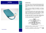
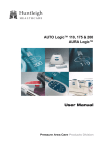
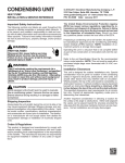
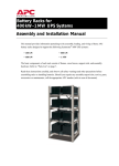
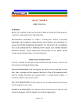
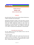
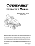
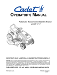
INSTALLATION INSTRUCTIONS
TEC40
ELECTRONIC CONTROLLER
BARD MANUFACTURING COMPANY
Bryan, Ohio 43506
Since 1914...Moving ahead, just as planned.
Manual:
Supersedes:
File:
Date:
2100-393C
2100-393B
Volume III Tab 19
07-11-02
CONTENTS
Shipping Damage ...................................................... 1
Figures
General ..................................................................... 1
Figure 1 Control Locations ................................... 5
Theory of Operation .................................................. 1
Figure 2 Four Unit Mode ...................................... 6
With and Without Economizers
Lead-Lag Change Over Time .................................... 1
Modes of Operation .................................................. 1
Installation Instructions ............................................. 3
Fire Suppression Circuit ............................................ 3
Adjustments .............................................................. 4
i
Figure 3 Three Unit Mode .................................... 7
With and Without Economizers
Figure 4 Two Unit Mode With Economizers ......... 8
Figure 5 Two Unit Mode Without Economizers .... 9
** IMPORTANT **
The equipment covered in this manual is to
be installed by trained, experienced service
and installation technicians. Please read
entire manual before proceeding.
In the event of a unit(s) failure, the change over time
jumper may be set to 0 days. This will prevent the
TEC40 from switching lead unit to the next unit. Push
the push-button to make a functional unit the lead unit
if necessary. If power is lost the controller will
remember which unit was the lead unit when power is
reapplied.
MODES OF OPERATION
SHIPPING DAMAGE
Upon receipt of equipment, the carton should be
checked for external signs of shipping damage. If
damage is found, the receiving party must contact the
last carrier immediately, preferably in writing,
requesting inspection by the carrier’s agent.
The TEC40 has four modes of operation.
1. Four Unit Mode
2. Three Unit Mode
3. Two Unit Alternating Mode
4. Two Unit Non-Alternating Mode.
STAGING DELAY PERIODS
GENERAL
These instructions explain the operation, installation
and troubleshooting of the TEC40 controller.
All internal wiring is complete. Only attach low
voltage field wiring to designated terminal strips.
The controller is for use with up to four (4) Bard air
conditioning wall mount series units. The TEC40 is for
use with units with or without economizers.
It is recommended that a five (5) minute compressor
time delay relay be factory or field installed in each
unit.
The TEC40 controller is suitable for both 50 and 60 HZ
operation.
THEORY OF OPERATION
The controller is used to control up to four wall mount
air conditioners from one thermostat. It provides total
redundancy for the structure and equal wear on all units.
It can be used with units with economizers but all units
must be equipped alike. That is, all must have
economizers or all must be without economizers. See
Figure 1 for component locations.
LEAD–LAG CHANGE OVER TIME
The lead- lag change over time period is user selectable.
Time periods available are 0, 1, 3, 7, 14 and 28 days.
Once every time period the lead unit will be advanced
to the next unit providing equal wear on the units. For
timer speed up, push and hold the change lead unit
push-button for one second. Timer speed up is supplied
for ease of trouble shooting.
Lead unit cycles between all 4 units in four unit mode;
between 1, 2 and 3 in three unit mode; and between
units 1 and 2 in both two unit modes.
The following delays are built in for both cooling and
heating: stage 1 – 0 seconds; stage 2 – 10 seconds;
stage 3 – 15 seconds; and stage 4 – 20 seconds. The
delays are active anytime there is a power interruption
or the controller ON–OFF switch is exercised.
FOUR UNIT MODE
In four unit mode the TEC40 will control four airconditioners with or without economizers. Make
connections per Figure 2 on Page 6.
Sequence of Operation – Cooling
First stage cooling set point is determined by the
position of the cooling set point potentiometer. On a
call for first stage cooling, the blower and either
economizer or compressor of the lead unit is energized.
The enthalpy control on the economizer will make the
decision as to which is energized. If not equipped with
economizers the compressor will energize. First stage
cooling LED will light.
Second stage cooling set point is 2.0 degrees warmer
than first stag cooling set point. On a call for second
stage cooling, the blower and either economizer of
compressor of the next unit is energized. The enthalpy
control on the economizer will make the decision as to
which is energized. If not equipped with economizer
the compressor will energize. Second stage cooling
LED will light.
Third stage cooling set point is 2.0 degrees warmer than
second stage cooling set point. On a call for third stage
cooling, the blower and either economizer is energized.
The enthalpy control on the economizer will make the
decision as to which is energized. If not equipped with
economizer the compressor will energize. Third stage
cooling LED will light.
Manual 2100-393
Page 1
Fourth stage cooling set point is 2.0 degrees warmer
than third stage cooling set point. On a call for fourth
stage cooling, the blower and either economizer or
compressor of the next unit is energized. The enthalpy
control on the economizer will make the decision as to
which is energized. If not equipped with economizer
the compressor will energize. Fourth stage cooling
LED will light.
Sequence of Operation – Heating
First stage heating set point is determined by
subtracting the dead band setting from cooling set point
setting. For example, if the cooling set point is 74
degrees and the dead band adjustment is set at 4 degrees
the heating set point is 70 degrees. On a call for first
stage heating, the blower and electric heat of the lead
unit is energized. First stage heating LED will light.
Second stage heating set point is 2.0 degrees colder than
first stage heating set point. On a call for second stage
heating, the blower and electric heat of the next unit is
energized. Second stage heating LED will light.
Third stage heating set point is 2.0 degrees colder than
second stage heating set point. On a call for third stage
heating, the blower and electric heat of the next unit is
energized. Third stage heating LED will light.
Fourth stage heating et point is 2.0 degrees colder than
third stage heating set point. On a call for fourth stage
heating, the blower and electric heat of the next unit is
energized. Fourth stage heating LED will light.
THREE UNIT MODE
In three unit mode the TEC40 will control three air
conditioners with or without economizers. Make
connections per Figure 3 on Page 7.
Sequence of Operation
The cooling and heating sequence of operation are the
same as four unit mode except that the fourth stage
heating or cooling is not available.
TWO UNIT NON-ALTERNATING MODE
In two unit non-alternating mode the TEC40 will
control two air conditioners with two speed or dual
compressors. Make connections per Figure 5 on Page 9.
Sequence of Operation – Cooling
First stage cooling set point is determined by the
position of the cooling set point potentiometer. On a
call for first stage cooling, the blower and low speed or
first compressor of the lead unit is energized. First
stage cooling LED will light.
Manual 2100-393
Page 2
Second stage cooling set point is 2.0 degrees warmer
than first stage cooling set point. On a call for second
stage cooling, the high speed or second compressor of
the lead unit will energize. Second stage cooling LED
will light.
Third stage cooling set point is 2.0 degrees warmer than
second stage cooling set point. On a call for third stage
cooling the blower and low speed or first compressor of
the lag unit will energize. Third stage cooling LED will
light.
Fourth stage cooling set point is 2.0 degrees warmer
than third stage cooling set point. On a call for fourth
stage cooling , the high speed or second compressor of
the lag unit will energize. Fourth stage cooling LED
will light.
Sequence of Operation – Heating
First stage heating set point is determined by
subtracting the dead bank setting from cooling set point
setting. For example, if the cooling set point is 74
degrees and the dead band adjustment is set at 4 degrees
the heating set point is 70 degrees. On a call for first
stage heating, the blower and electric heat of the lead
unit is energized. First stage heating LED will light.
Second stage heating set point is 2.0 degrees colder than
first stage heating set point. On a call for second stage
heating, the second electric heat (if equipped) of the
lead unit is energized. Second stage heating LED will
light.
Third stage heating set point is 2.0 degrees colder than
second stage heating set point. On a call for third stage
heating, the blower and electric heat of the lag unit is
energized. Third stage heating LED will light.
Fourth stage heating set point is 2.0 degrees colder than
third stage heating set point. On a call for fourth stage
heating, the second electric heat (if equipped) of the lag
unit is energized. Fourth stage heating LED will light
TWO UNIT ALTERNATING MODE
In two unit alternating mode the TEC40 will control
two air conditioners with two speed or dual compressor
or two air conditioners with economizers with full
redundancy. Make connections per Figure 4 on Page 8.
Sequence of Operation – Cooling with
Economizers
First stage cooling set point is determined by the
position of the cooling set point potentiometer. On a
call for first stage cooling, the blower and either
economizer or compressor of the lead unit is energized.
The enthalpy control on the economizer will make the
decision as to which is energized. First stage cooling
LED will light.
Second stage cooling set point is 2.0 degrees warmer
than first stage cooling set point. On a call for second
stage cooling, the blower and either economizer or
compressor of the lag unit is energized. The enthalpy
control on the economizer will make the decision as to
which is energized. Second stage cooling LED will
light.
Third stage cooling set point is 2.0 degrees warmer than
second stage cooling set point. On a call for third stage
cooling, the compressor of the lead unit will energize
and the economizer will return to minimum position if
open. Third stage cooling LED will light.
Fourth stage cooling set point is 2.0 degrees warmer
than third stage cooling set point. On a call for fourth
stage cooling, the compressor of the lag unit will
energized and the economizer will return to minimum
position if open. Fourth stage cooling LED will light.
Sequence of Operation – Heating
First stage heating set point is determined by
subtracting the dead and setting from cooling set point
setting. For example, if the cooling set point is 74
degrees and the dead band adjustment is set at 4 degrees
the heating set point is 70 degrees. On a call for first
stage heating, the blower and electric heat of the lead
unit is energized. First stage heating LED will light.
Second stage heating set point is 2.0 degrees colder than
first stage heating set point. On a call for second stage
heating, the electric heat of the lag unit is energized.
Second stage heating LED will light.
Third stage heating set point is 2.0 degrees colder than
second stage heating set point. On a call for third stage
heating, the second electric heat (if equipped) of the
lead unit is energized. Third stage heating LED will
light.
Fourth stage heating set point is 2.0 degrees colder than
third stage heating set point. On a call for fourth stage
heating, the second electric heat (if equipped) of the lag
unit is energized. Fourth stage heating LED will light.
NSTALLATION INSTRUCTIONS
MOUNTING
Included in the controller carton is the controller and
installation instructions.
The controller should be installed on a vertical wall
approximately four (4) feet above the floor away from
drafts and outside doors or windows. Four (4)
mounting holes are provided for mounting to the wall,
and holes for conduit connections are provided in both
the base, side and top of the controller. The controller
should not be mounted directly to a block wall; space
away from wall with insulation or plywood.
Once mounted, slide the thermistor sensor down into
the fitting on the bottom of the TEC40. Position the
sensor so that 15/16 inch is protruding from the bottom
of the fitting. Tighten the fitting to hold the sensor in
position.
LOW VOLTAGE FIELD WIRING
The TEC40 is powered from the air conditioners that it
is controlling, 24 VAC, 50/60 HZ, low voltage only.
Circuitry in the TEC40 isolate the power supplies of all
connected air conditioners so that no back feeds or
phasing problems can occur. Additionally if one or
more air conditioners loose power the TEC40 and the
other air conditioners are unaffected and will continue
to operate normally.
Connect the low voltage field wiring from each unit per
the low voltage field wiring diagrams in Figure 2, 3, 4
or 5 depending on the mode of operation desired.
FIRE SUPPRESSION CIRCUIT
To disable the TEC40 and shut down all air
conditioners, terminal F1 and F2 may be used. The F1
and F2 terminals must be jumpered together for normal
operation. A normally closed set of contacts may be
connected across the terminals and the factory jumper
removed for use with a field installed fire suppression
system. The contacts must open if a fire is detected.
Contacts should be rated for pilot duty operation at
2 amp 24 VAC minimum.
IMPORTANT NOTE: Bard models employ an
electronic blower control that has a 60-second blower
off-delay. In order to have immediate shutdown of the
blower motor in addition to disabling the run function
of the air conditions will require a simple wiring
modification at the blower control located in the
electrical control panel of the air conditioners being
controlled by the lead/lag controller. To eliminate the
60- second blower off-delay disconnect and isolate
the wire that is factory connected to the “R” terminal
to the electronic blower control, and then connect a
jumper from the “G” terminal on the blower control
to the “R” terminal on the blower control. The
electronic blower control will now function as an onoff relay with no off-delay, and the blower motor will
stop running immediately when the F1-F2 fire
suppression circuit is activated (opened).
Manual 2100-393
Page 3
ADJUSTMENTS
See Figure 1.
COOLING SET POINT
Set the cooling set point in degrees C° or F° as
indicated on the front of the TEC40.
DEAD BAND
The dead band is the span between heating set point and
cooling set point where no heating or cooling takes
place. The cooling set point minus the dead band
equals the heating set point. Adjustable from 4° to
20° F.
If the jumper is set to 7 days (or other selected choice),
units will rotate upwards: first to second, second to
third, third to fourth, and fourth to first place. If
connected for three units then three will go to first, and
fourth position is ignored.
The 0 day position is supplied in the event of a unit
failure or if only one air conditioner is used with the
TEC40. If the unit needs to run for a time and not
switch to the lag unit, set the jumper to “0” and push the
lead change push-button to make the functional or
single unit the lead unit. When the jumper is in the 0
position the lead unit will never switch.
TEST MODE JUMPER – UNDER COVER
Turn the potentiometer fully counter clockwise for 4°
dead band. Turn fully clockwise for 20° dead band.
The arrow on top of the potentiometer does not indicate
dead band setting.
There is a test mode to accelerate the timing circuit
from days to seconds. For example, if the timing
selection jumper plug were set to the 7 day position,
then utilizing the test mode feature the lead unit would
advance in 7 seconds.
LEAD CHANGE PUSH-BUTTON
To use the test feature take the following steps:
Pushing the lead change push-button will immediately
change the lead unit to the lag unit. It also resets the
lead/lag change over timer to zero and restarts the
selected timing period.
1. Turn the on/off switch to OFF.
ON/OFF SWITCH – UNDER COVER
This disables the TEC40. This switch must be ON for
any heating or cooling to operate.
NOTE: Whenever the on/off switch is first turned ON,
all 4 red LED’s for lead unit indication will
flash 4 or 5 times as the controller sequences
itself, and then will revert to whichever unit
was lead when on/off switch was turned OFF.
2. Place the jumper across the test mode pins.
3. Turn the on/off switch to ON.
4. The lead unit will now advance in upward sequence
through the enabled unit positions.
5. To stop the accelerated sequence turn the on/off
switch to OFF, remove the jumper, and then turn the
on/off switch back ON.
6. After the 4 red LED’s stop flashing the lead unit may
be the one indicated at the time the on/off switch was
turned OFF or it may be the next one up, depending
on where the timer was in the accelerated sequence
when switch was turned OFF.
CHANGING SELECTABLE FEATURES
To change any selectable feature turn on/off switch
OFF. Change jumpers as necessary and turn switch
ON. Jumper changes do not take effect unless on/off
switch is turned OFF, jumper plug moved, and on/off
switch turned back ON.
CHANGE OVER TIME JUMPER – UNDER
COVER
The change over period for the sequence can be
adjusted to 0, 1, 3, 7, 14 or 28 days.
Manual 2100-393
Page 4
OPERATION MODE JUMPER – UNDER COVER
Position jumper across pins 4 for four unit mode.
Position jumper across pins 3 for three unit mode.
Position jumper across pins 2 for two unit nonalternating mode. Remove jumper for two unit
alternating mode.
CONTINUOUS BLOWER JUMPER – UNDER
COVER
Position jumper across pins for continuous blower on
the lead unit. Remove jumper to have the lead unit
blower cycle with the compressor.
FIGURE 1
CONTROL LOCATIONS
7960-477
Manual 2100-393
Page 5
Manual 2100-393
Page 6
FIGURE 2
FOUR UNIT MODE WITH ECONOMIZERS
FOUR UNIT MODE WITHOUT ECONOMIZERS
FIGURE 3
THREE UNIT MODE WITH ECONOMIZERS
THREE UNIT MODE WITHOUT ECONOMIZERS
Manual 2100-393
Page 7
Manual 2100-393
Page 8
FIGURE 4
TWO UNIT MODE WITH ECONOMIZERS
MIS-1657A
FIGURE 5
TWO UNIT MODE WITHOUT ECONOMIZERS
Manual 2100-393
Page 9
MIS-1658