1
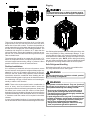
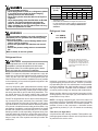
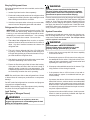
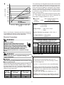
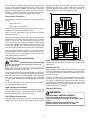
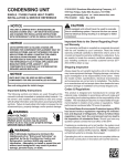
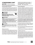
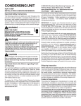
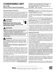
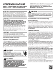
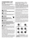
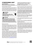
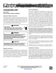
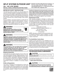
CONDENSING UNIT
HEAT PUMP
INSTALLATION & SERVICE REFERENCE
Important Safety Instructions
The following symbols and labels are used throughout this
manual to indicate immediate or potential safety hazards. It
is the owner’s and installer’s responsibility to read and comply with all safety information and instructions accompanying
these symbols. Failure to heed safety information increases
the risk of personal injury, property damage, and/or product
damage.
WARNING
HIGH VOLTAGE!
Disconnect ALL power before servicing.
Multiple power sources may be present.
Failure to do so may cause property damage,
personal injury or death.
ONLY individuals meeting the requirements (at a
minimum) of an “Entry Level Technician” as specified
by the Air Conditioning, Heating, and Refrigeration
Institute (AHRI) may use this information. Attempting
to install or repair this unit without such background
may result in product damage, personal injury, or
death.
CAUTION
Scroll equipped units should never be used to evacuate
the air conditioning system. Vacuums this low can cause
internal electrical arcing resulting in a damaged or failed
compressor.
Shipping Inspection
Always keep the unit upright; laying the unit on its side or top
may cause equipment damage. Shipping damage, and subsequent investigation is the responsibility of the carrier. Verify
the model number, specifications, electrical characteristics,
and accessories are correct prior to installation. The distributor or manufacturer will not accept claims from dealers for
transportation damage or installation of incorrectly shipped
units.
Codes & Regulations
This product is designed and manufactured to comply with
national codes. Installation in accordance with such codes
and/or prevailing local codes/regulations is the responsibility
of the installer. The manufacturer assumes no responsibility
for equipment installed in violation of any codes or regulations.
© 2010-2011 Goodman Manufacturing Company, L.P.
5151 San Felipe, Suite 500, Houston, TX 77056
www.goodmanmfg.com -or- www.amana-hac.com
P/N: IO-393B Date: January 2011
The United States Environmental Protection Agency
(EPA) has issued various regulations regarding the introduction and disposal of refrigerants. Failure to follow
these regulations may harm the environment and can lead
to the imposition of substantial fines. Should you have
any questions please contact the local office of the EPA.
If replacing a condensing unit or air handler, the system must
be manufacturer approved and Air Conditioning and Refrigeration Institute (AHRI) matched. NOTE: Installation of unmatched systems is strongly discouraged.
Operating the unit in a structure that is not complete (either
as part of new construction or renovation) will void the warranty.
Refer to the unit Specification Sheet for the recommended
indoor model selection. NOTE: This unit must be used with a
purchased single stage room thermostat with 24 VAC control circuitry.
Installation Clearances
This unit is designed for outdoor installations only. Special
consideration must be given to location of the condensing
unit(s) in regard to structures, obstructions, other units, and
any/all other factors that may interfere with air circulation.
Where possible, the top of the unit should be completely unobstructed; however, if vertical conditions require placement
beneath an obstruction there should be a minimum of 60
inches between the top of the unit and the obstruction(s).
The specified dimensions meet requirements for air circulation only. Consult all appropriate regulatory codes prior to
determining final clearances.
Another important consideration in selecting a location for
the unit(s) is the angle to obstructions. Either side adjacent
the valves can be placed toward the structure provided the
side away from the structure maintains minimum service clearance. Corner installations are strongly discouraged.
Rigging
12"
60"
To avoid possible injury or death, all panels must be
in position and secured before lifting this equipment
12"
12"
24"
This unit can be located at ground floor level or on flat roofs.
At ground floor level, the unit must be on a solid, level foundation that will not shift or settle. To reduce the possibility of
sound transmission, the foundation slab should not be in contact with or be an integral part of the building foundation. The
foundation slab should be a minimum of 6” wider than the
unit in all directions. Ensure the foundation is sufficient to support the unit. A concrete slab raised above ground level provides a suitable base.
Use field-supplied spreader bars when lifting the unit to minimize the possibility of lifting cable/straps damage. To protect the cabinet louvers, use protective material such as plywood behind the cable/straps. Arrange the straps to form a
central suspension point. NOTE: When raising and setting
the unit, observe all safety rules. Remove shipping skid and
all protection and lifting material after the unit is in place.
The selected site should be no greater than 50’ below or 70’
above the evaporator section. For optimum performance, the
minimum length interconnecting tubing is preferred. When
possible minimize the amount of bends and turns.
Safe Refrigerant Handling
Rooftop Installations
While these items will not cover every conceivable situation, they should serve as a useful guide.
If it is necessary to install this unit on a roof structure, ensure
the roof structure can support the weight and that proper consideration is given to the weather-tight integrity of the roof.
Since the unit can vibrate during operation, sound vibration
transmission should be considered when installing the unit.
Vibration absorbing pads or springs can be installed between
the condensing unit legs or frame and the roof mounting assembly to reduce noise vibration.
WARNING
To avoid possible injury, explosion or death, practice
safe handling of refrigerants.
WARNING
Refrigerants are heavier than air. They can "push out"
the oxygen in your lungs or in any enclosed space.To
avoid possible difficulty in breathing or death:
• Never purge refrigerant into an enclosed room or
space. By law, all refrigerants must be reclaimed.
• If an indoor leak is suspected, throughly ventilate the
area before beginning work.
• Liquid refrigerant can be very cold. To avoid possible
frostbite or blindness, avoid contact and wear gloves
and goggles. If liquid refrigerant does contact your
skin or eyes, seek medical help immediately.
• Always follow EPA regulations. Never burn refrigerant, as poisonous gas will be produced.
NOTE: These units require special location consideration in
areas of heavy snow accumulation and/or areas with
prolonged continuous subfreezing temperatures. Heat pump
unit bases have cutouts under the outdoor coil that permit
drainage of frost accumulation. Situate the unit to permit free
unobstructed drainage of the defrost water and ice. A minimum
3" clearance under the outdoor coil is required in the milder
climates.
In more severe weather locations, it is recommended that the
unit be elevated to allow unobstructed drainage and air flow.
2
Cond Unit
(Tons)
To avoid possible explosion:
• Never apply flame or steam to a refrigerant cylinder.
If you must heat a cylinder for faster charging,
partially immerse it in warm water.
• Never fill a cylinder more than 80% full of liquid refrigerant.
• Never add anything other than R410A to an R-410A
cylinder. The service equipment used must be
listed or certified for the type of refrigerant used.
• Store cylinders in a cool, dry place. Never use a cylinder as a platform or a roller.
7 1/2
10
REFRIGERANT LINE LENGTH (ft)
0-24
25-49*
50-74**
Line Diameter (In. OD)
Suct Liq Suct Liq Suct Liq
1 3/8 5/8 1 3/8 5/8 1 3/8 5/8
1 3/8
5/8
1 5/8
5/8
1 5/8
5/8
* Full rating line size
** These sizes are suitable for line lengths of 74 feet or less.
For lines greater than 74 feet in length or vertical elevation
changes more than 50 feet, contact your distributor for
assistance.
Refrigerant Lines
WARNING
To avoid possible explosion, use only returnable (not
disposable) service cylinders when removing refrigerant from a system.
• Ensure the cylinder is free of damage which could
lead to a leak or explosion.
• Ensure the hydrostatic test date does not exceed
5 years.
• Ensure the pressure rating meets or exceeds 400
lbs.
When in doubt, do not use cylinder.
Refrigerant Lines
Mounting the condensing unit above
the evaporator coil will require an oil trap
in the suction line. Install one oil trap at
the evaporator, for a height difference of
more than 15 feet between indoor and
outdoor units.
CAUTION
The compressor POE oil for R-410A units is extremely
susceptible to moisture absorption and could cause
compressor failure. Do not leave system open to atmosphere any longer than necessary for installation.
NOTE: For improved refrigerant management, equip the
evaporator coil with a field-supplied thermal expansion valve
(TXV) and the liquid line with a field-supplied liquid line
solenoid. Ensure the solenoid is installed as close as possible
to the evaporator coil to prevent refrigeration migration in the
compressor “OFF” cycle.
Insulation is necessary to prevent condensation from forming and dropping from the suction line. Armflex® (or satisfactory equivalent) with 3/8” min. wall thickness is recommended.
In severe conditions (hot, high humidity areas) 1/2” insulation may be required. Insulation must be installed in a manner which protects tubing from damage and contamination.
Use only refrigerant grade (dehydrated and sealed) copper
tubing to connect the condensing unit with the indoor evaporator. After cutting the tubing, install plugs to keep refrigerant tubing clean and dry prior to and during installation. Tubing should always be cut square keeping ends round and
free from burrs. Clean the tubing to prevent contamination.
Where possible, drain as much residual compressor oil from
existing systems, lines, and traps; pay close attention to low
areas where oil may collect.
Do NOT let refrigerant lines come in direct contact with plumbing, ductwork, floor joists, wall studs, floors, and walls. When
running refrigerant lines through a foundation or wall, openings should allow for sound and vibration absorbing material
to be placed or installed between tubing and foundation. Any
gap between foundation or wall and refrigerant lines should
be filled with a pliable silicon-based caulk, RTV or a vibration
damping material. Avoid suspending refrigerant tubing from
joists and studs with rigid wire or straps that would come in
contact with the tubing. Use an insulated or suspension type
hanger. Keep both lines separate and always insulate the
suction line.
NOTE: If changing refrigerant types, ensure the indoor coil
and metering device is compatible with the type of refrigerant
being used; otherwise, the indoor coil must be replaced. To
facilitate oil return to the compressor, a horizontal suction
line should be pitched (1/2” per 10’ toward the condensing
unit.
Filter Drier and Sight Glass
A liquid line filter drier is factory installed. Field-install the supplied sight glass/moisture indicator on the liquid line as close
as practical to the service valve.
3
Burying Refrigerant Lines
WARNING
If burying refrigerant lines can not be avoided, use the following checklist.
To avoid possible explosion, the line from the
nitrogen cylinder must include a pressure regulator
and a pressure relief valve. The pressure relief valve
must be set to open at no more than 150 psig.
1. Insulate liquid and suction lines separately.
2. Enclose all underground portions of the refrigerant lines
in waterproof material (conduit or pipe) sealing the ends
where tubing enters/exits the enclosure.
Pressure test the system using dry nitrogen and soapy water
to locate leaks. If you wish to use a leak detector, charge the
system to 10 psi using the appropriate refrigerant then use
nitrogen to finish charging the system to working pressure
then apply the detector to suspect areas. If leaks are found,
repair them. After repair, repeat the pressure test. If no leaks
exist, proceed to system evacuation.
3. If the lines must pass under or through a concrete slab,
ensure lines are adequately protected and sealed.
Refrigerant Line Connections
IMPORTANT: To avoid overheating the service valve, TXV
valve, or filter drier while brazing, wrap the component with
a wet rag, or use a thermal heat trap compound as recommended by the compound manufacturer. Use a brazing
alloy of 2% minimum silver content. Do not use flux.
System Evacuation
Condensing unit liquid and suction valves are closed to contain the charge within the unit. The unit is shipped with the
valve stems closed and caps installed. Do not open valves
until the system is evacuated.
1. The ends of the refrigerant lines must be cut square,
deburred, cleaned, and be round and free from nicks or
dents. Any other condition increases the chance of a
refrigerant leak.
WARNING
REFRIGERANT UNDER PRESSURE!
Failure to follow proper procedures may cause
property damage, personal injury or death.
2. This unit is factory shipped with 2 lbs. of R-410A holding charge. “Sweep” the refrigerant line with nitrogen or
inert gas during brazing to prevent the formation of copper-oxide inside the refrigerant lines.
1. Connect the vacuum pump with 250 micron capability
to the service valves.
3. After brazing, quench the joints with water or a wet cloth
to prevent overheating of the service valve.
2. Evacuate the system to 250 microns or less using suction and liquid service valves. Using both valves is necessary as some compressors create a mechanical seal
separating the sides of the system.
4. Ensure the filter drier paint finish is intact after brazing.
If the paint of the steel filter drier has been burned or
chipped, repaint or treat with a rust preventative. This
is especially important on suction line filter driers which
are continually wet when the unit is operating.
3. Close pump valve and hold vacuum for 10 minutes. Typically pressure will rise during this period.
• If the pressure rises to 1000 microns or less and remains steady the system is considered leak-free; proceed to startup.
NOTE: Be careful not to kink or dent refrigerant lines. Kinked
or dented lines will cause poor performance or compressor
damage.
•
Do NOT make final refrigerant line connection until plugs are
removed from refrigerant tubing.
NOTE: Before brazing, verify indoor piston size by checking
the piston kit chart packaged with indoor unit.
Leak Testing
(Nitrogen or Nitrogen-Traced)
If pressure rises above 1000 microns but holds steady
below 2000 microns, moisture and/or noncondensibles
may be present or the system may have a small leak.
Return to step 2: If the same result is encountered check
for leaks as previously indicated and repair as necessary then repeat evacuation.
• If pressure rises above 2000 microns, a leak is present.
Check for leaks as previously indicated and repair as
necessary then repeat evacuation.
WARNING
To avoid the risk of fire or explosion, never use
oxygen, high pressure air or flammable gases for leak
testing of a refrigeration system.
4
The condensing unit rating plate lists pertinent electrical data
necessary for proper electrical service and overcurrent protection. Wires should be sized to limit voltage drop to 2%
(max.) from the main breaker or fuse panel to the condensing unit. Consult the NEC, CEC, and all local codes to determine the correct wire gauge and length. The wire size must
be sufficient to carry the Minimum Circuit Ampacity (MCA)
listed on the serial plate.
5000
VACUUM IN MICRONS
4500
4000
LEAK(S)
PRESENT
3500
3000
The supply voltage can be unbalanced (phase to phase) within
2%. The following formula can be used to determine the
percentage of voltage unbalance for your unit.
2500
2000
CONDENSIBLES OR SMALL
LEAK PRESENT
1500
Percentage
= 100 x
Voltage
Unbalance
1000
NO LEAKS
NO CONDENSIBLES
500
Max. Voltage Deviation From
Average Voltage
Average Voltage
Example:
0
1
2
3
4
5
6
MINUTES
7
8
9
10
L1-L2 = 220V
L2-L3 = 216V
Average Voltage = (220 + 216 + 213)/3
= 649/3
Refer to the Remote Condensing Unit Service Manual for
more detailed instructions on system evacuation, preliminary
charge adjustment, and final charge adjustment.
Maximum Deviation from Average = 220 - 216 = 4
% Voltage Unbalance = 100 x (4/216)
= 400/216
Electrical Connections
MAXIMUM ALLOWABLE LENGTH IN FEET
TO LIMIT VOLTAGE DROP TO 2%
WARNING
HIGH VOLTAGE!
Disconnect ALL power before servicing.
Multiple power sources may be present.
Failure to do so may cause property damage,
personal injury or death due to electric shock.
Wiring must conform with NEC or CEC and all
local codes. Undersized wires could cause
poor equipment performance, equipment damage
or fire.
Minimum Circuit Ampacity (MCA)
Wire Size
(AWG)
10
15
20
25
30
35
40
14
75
50
37 NR NR NR NR
12
118 79
59
47 NR NR NR
10
188 125 95
75
63
54 NR
8
301 201 150 120 100 86
75
6
471 314 235 188 157 134 118
*Based on NEC 1996
WARNING
To avoid the risk of fire or equipment damage, use
copper conductors.
EXAMPLE:
NOTICE
The distance from the building to the unit is 75’.
Calculate the minimum wire size assuming no more
than 2% voltage drop.
Units with reciprocating compressors and non-bleed TXV’s
require a Hard Start Kit.
This unit is designed for three phase operation. DO NOT OPERATE ON A SINGLE PHASE POWER SUPPLY. Measure
the power supply to the unit. The supply voltage must be in
agreement with the unit rating plate power requirements and
within the range listed below:
RATED
VOLTAGE
208/230V
460V
MCA for 7-1/2 ton 230V unit = 43.3 (from S&R plate).
Applying previous table wire sizes less than #8 AWG
cannot be used for circuits which have a rating of 45A.
The #8 wire is not suitable since the maximum length
for a 45A circuit is 68’.
Solution: Use a #6 AWG wire suitable up to 110’.
MINIMUM SUPPLY MAXIMUM SUPPLY
VOLTAGE
VOLTAGE
197
414
45
NR
NR
NR
68
110
NOTE: It is the contractors’s responsibility to follow the
NEC(USA) or CEC (Canada) when sizing the service
253
506
5
Local codes often require a disconnect switch located near
the unit; do not install the switch on the unit. Refer to the
installation instructions supplied with the indoor furnace/air
handler for specific wiring connections and indoor unit configuration. Likewise, consult the instructions packaged with
the thermostat for mounting and location information.
The wires should be no smaller than 18 AWG and the field
connection for this circuit must be made in the unit control
box using solderless connectors (i.e. wire nuts). See the following diagram for a typical low voltage hook-up.
SINGLE STAGE LOW VOLTAGE HOOK-UP
Overcurrent Protection
THERMOSTAT
Y
The following overcurrent protection devices are approved
for use.
•
Time delay fuses
•
HACR type circuit breakers
O
C
W2
R
G
CONDENSING
UNIT
AIR
HANDLER
GREEN
YELLOW
RED
ORANGE
These devices have sufficient time delay to permit the motorcompressor to start and accelerate its load.
BROWN
RED
Refer to the unit serial plate for the maximum overcurrent
protection permitted.
Run all line voltage wiring a conduit from the service disconnect box to the unit. Refer to the NEC (USA) or CEC (Canada)
codes for the correct size conduit based on the wire size.
The conduit enters the control box through the hole provided
in the bottom. NOTE: The control box hole is sized for 3/4”
conduit. If permitted by code, a flexible conduit is preferred to
minimize vibration transmission from the unit to the building.
WHITE
WHITE
BLUE
BLUE
TWO STAGES LOW VOLTAGE HOOK-UP
THERMOSTAT
Y
O
CONDENSING
UNIT
YELLOW
Connect the line voltage wires to the L1, L2, and L3 terminals of the definite purpose contactor (located in the unit control box). Refer to the wiring diagram attached to the unit
when making these connections.
C
W1
W2
R
G
AIR
HANDLER
GREEN
RED
ORANGE
RED
BROWN
WHITE
WHITE
BLUE
BLUE
Three Phase Compressor Rotation
NOTE: For two-stage units, refer to the Installation Instructions
supplied with the variable speed indoor units for field wiring
connections.
CAUTION
Use care when handling scroll compressors. Dome temperatures could be hot.
System Start Up
Three phase scrolls are power phase dependent and can
compress in more than one direction.
Never operate the compressor with the suction valve closed
to test the compressor’s pumping efficiency. In some cases,
this can result in serious compressor damage and loss of
warranty coverage.
Verify proper rotation for three phase compressors by ensuring the suction pressure drops and discharge pressure rises
when the compressor is energized. NOTE: When operated
in reverse, a three phase scroll compressors is noisier and
its current draw substantially reduced compared to marked
values.
For the 7-1/2 ton unit starting charge should be 15 lbs. of R-410A
and 18 lbs. for the 10 ton unit. The length of line set, indoor
unit airflow, condensing unit location and number of tubing
fittings will have an impact on final unit charge amount. Turn
the electrical power on, and let the system run. Wait for the
refrigerant pressures to stabilize.
To correct, disconnect power and switch any two leads at
the unit contactor and re-observe.
High Voltage Connections
Charge Verification
Route power supply and ground wires through the high voltage port and terminate in accordance with the wiring diagram provided inside the control panel cover.
WARNING
REFRIGERANT UNDER PRESSURE!
Low Voltage Connections
• Do not overcharge system with refrigerant.
• Do not operate unit in a vacuum or at negative pressure.
Failure to follow proper procedures may cause
property damage, personal injury or death.
Condensing unit control wiring requires a five-conductor low
voltage circuit from the room thermostat (without options).
6
After achieving the proper subcooling and a sufficient discharge temperature, make small adjustment to expansion
valve stem to reach 8º to 10ºF of super heat. Adjusting the
valve stem in clockwise, superheat increase, adjusting the
valve stem out, counter clockwise, super heat decreases. If
the system is performing properly, reinstall the service port
caps and the valve bonnets. With the valve opened, the valve
bonnet is the primary seal against refrigerant leaks. Apply
two drops of clean oil to the cap threads, allowing the oil to
run down to the inner cap seal surface. Close caps fingertight. Then tighten cap additional two to three hex flats.
CAUTION
NOTICE
Violation of EPA regulations may result in fines or other
penalties.
CAUTION
System Charging Heating Mode. Measure the hot gas discharge at the compressor to check the system charge in heat
mode.
Operating the compressor with the suction valve closed will
void the warranty and cause serious compressor damage.
1. Allow the system to operate for at least 20 minutes.
Final Charge Adjustment
The outdoor temperature must be 60°F or higher. Set the
room thermostat to COOL, fan switch to AUTO, and set the
temperature control well below room temperature.
2. Attach and insulate an electronic thermometer to the
hot gas discharge line mid way between the compressor and the reversing valve. Note: The thermometer is
to be well insulated to prevent ambient influences.
After system has stabilized per startup instructions, check
subcooling and superheat as detailed in the following section.
3. Adjust the charge to maintain a clear sight glass.
Expansion Valve System
4. Allow the compressor to operate for about 10 additional
minutes and measure the hot gas discharge temperature.
NOTE: The expansion valve bulb must be in place on the
suction line and insulated.
Expansion Valve Indoor Coils:
Outdoor Temperature Over 60ºF. When the outdoor temperature is above 60ºF, charge the system with the room
thermostat set in the “Cooling” mode and the fan operating in
the “Auto” position.
5. Using an additional electronic thermometer, measure
the ambient.
6. Adjust the charge until the hot gas temperature equals
105ºF + ambient (+ or – 5ºF). Remove charge to increase
the temperature.
Outdoor Temperature Below 60ºF. When the outdoor temperature is below 60ºF, charge the system with the room thermostat set in the “Heat” mode and the fan operating in the
“Auto” position.
NOTE: When adjusting the charge, allow the compressor to
operate for about 10 minutes before taking readings.
System Charging Cooling Mode. At stabilized cooling conditions and with an outdoor temperature of 60°F or higher,
the system should have from 9°F to 13°F subcooling. For a
proper subcooling reading, measure the refrigerant pressure
and temperature at the outdoor unit’s liquid line service valve.
If you have less than 9°F subcooling, add charge. If you have
more than 13°F subcooling, remove charge.
NOTE: Subsequent opening and replace of the cap will
require only 1/2 to 1 hex flat. See the table below for the
torque required for an effective seal on the valve bonnet (1/6
turn past finger tight.
TUBING SIZE
5/8
1 3/8
While reaching the proper subcooling level it is important to
know the discharge line temperature. This temperature should
be at least 80ºF over ambient or unit is flooding back to compressor. If flooding (i.e. low discharge line temperature) occurs, adjust valve stem on expansion valve inward (clockwise viewing end of expansion valve). This will increase the
super heat.
TORQUE
(ft-lbs)
14
16
After closing the valve bonnet, perform a final refrigerant leak
test on the valves and sweat connections. Return the room
thermostat to the desired settings.
Defrost Control Adjustments
This heat pump uses a Time/Temperature method for defrost. A thermal sensor electrically set to “Normally Open” is
wired to the electronic defrost control located in the control
box. The thermal sensor attached to the condenser coil determines the outdoor coil temperature.
7
Both coil temperature and compressor “run time” determine
defrosting of the outdoor coil. Adjustments to the defrost timing selection can be changed from the 60 minute factory setting to either 30 or 90 minutes by moving the jumper on the
defrost control. For the system to initiate a defrost, the following statements must be true:
•
The Defrost Sensor is closed, and
•
The compressor “run time” is equal to the timing selection on the defrost board.
7. After the thermostat has closed, short across the test
pins with the a screwdriver blade until the reversing valve
shifts. This could take up to 21 seconds depending upon
the position of the timing setting on the defrost board.
Immediately upon the action of the reversing valve, remove the short. Note: If this short is not removed immediately, the defrost activity will last only 2.3 seconds.
8. After defrost has terminated (up to 10 minutes) check
the defrost thermostat for 24V between “DFT” and “C”.
This reading should be 0V (open sensor).
During defrost the following actions occur:
9. Shut off power to the unit.
1. The reversing valve is energized and the heat pump
operates in the cooling mode.
2. The airhandler auxiliary heat (if equipped) is activated.
HIGH VOLTAGE!
Disconnect ALL power before servicing.
Multiple power sources may be present.
Failure to do so may cause property damage,
personal injury or death.
3. The condenser fan motor is shut-off.
If the defrost cycle has not terminated after ten (10) minutes
the control will override the defrost sensor and revert to a
heating mode.
The defrost control has test pins which can be useful when
troubleshooting in the heating mode. These test pins accelerate the compressor run time counter. The suggested
method for accessing this feature is:
10. Replace outdoor fan motor wire removed in Step d.
NOTE: The compressor “run time’ is accumulative during
multiple heating cycles. The timer will reset to zero only when
the defrost sensor returns to an open condition. If the room
thermostat is operating in the “EM HT” mode, no accumulation
of compressor time is recorded.
1. Run unit in heat mode.
2. Check unit for proper charge.
NOTE: Bands of frost indicate low refrigerant charge.
3. Shut off power to unit.
HIGH VOLTAGE!
Disconnect ALL power before servicing.
Multiple power sources may be present.
Failure to do so may cause property damage,
personal injury or death.
4. Disconnect outdoor fan by removing the purple lead from
the Condenser Fan Defrost Relay.
5. Restart unit and allow frost to accumulate.
6. After a few minutes the defrost thermostat should close.
To verify the position of the thermostat check for 24V
between “DFT” and “C” on the defrost board. Should
the defrost thermostat fail to close after a heavy buildup of frost and the thermostat is less than 28°, the thermostat is to be replaced.
Qualified Installer/Servicer Only
When troubleshooting, the first step should always be to check
for clean coils, clean filter(s), and proper airflow. Indoor airflow should be 375 to 425 CFM per ton of cooling based on
the size of the outdoor unit. The most common way of establishing indoor airflow is heating temperature rise. Indoor airflow will then be (Heating output of equipment) / (1.1 x temp.
rise). In other cases, measurement of external static pressure is helpful. For details, see the Installation Instructions
for your indoor unit.
8
TROUBLE SHOOTING ANALYSIS TABLE
COMPLAINT
PROBABLE CAUSE
1. Excessive charge of refrigerant in system.
2. Inadequate supply of air across the
condenser coil.
3. Non-condensate gases in the system.
1. High Head Pressure
1.
2.
1.
2.
3.
2. Low Head Pressure
3. Low Suction Pressure
4. High Suction Pressure
System low on refrigerant.
Compressor valves broken.
Liquid line valve closed.
Restricted liquid line.
The bulb of the thermal expansion valve
has lost its charge.
4. System low on refrigerant.
5.
6.
7.
8.
1.
2.
3.
1.
2.
3.
5. Compressor will not start.
4.
5.
6.
Dirty filters.
Coil frosted up.
Flash gas in the liquid line.
Quantity of air through evaporator not adequate.
Expansion valve stuck open.
Expansion valve bulb not in contact with
suction line.
Suction and/or discharge valve leaking or broken.
Disconnect switch open.
Blow fuse or fuse at disconnect switch.
Thermostat set too high.
Selector switch in "Off" position.
Contactor and/or relay coils burned out.
Loose or open electrical connection in either
the control or power circuit.
REMEDY
1. Purge or pump-down excessive charge.
2. Make certain that coil is not fouled in any
way, or that air is not re-circulating.
3. Purge these gases from the system.
Recharge system, if necessary.
1. Charge system until sight glass is clear of bubbles.
2. Replace compressor.
1. Open the liquid line valve.
2. Replace filter-dryer.
3. Detach the bulb from the suction line and hold
in one hand. If no liquid refrigerant goes through
the valve, replace the valve.
4. Test the unit for leaks. Add refrigerant until sight
glass is free from bubbles, after repairing leak.
5. Clean or replace filter.
6. Defrost and clean coil. Clean or replace filters.
7. Excessive liquid line drop. Check liquid line size.
8. Increase the blower speed.
1. Correct valve action or replace the valve.
2. Fasten bulb securely to suction line.
3. Replace compressor.
1. Close the disconnect switch.
2. Check the cause of failure and replace the fuse.
3. Adjust to lower temperature.
4. Turn selector switch knob to "Cool" position.
5. Replace contactor and/or relay.
6. Inspect and secure all electrical connections.
Common Causes for Unsatisfactory Operation of Heat Pumps in Heating Mode
Dirty Filters
Dirty filters or inadequate airflow through the indoor coil. Failure to keep clean filters and adequate airflow (375-425 CFM/
ton) will cause excessive discharge pressures that may cause the high-pressure switch to function.
Low Return Air Temperatures
Return ductwork temperatures that are less than 60°F will cause low discharge pressure, low suction pressure and excessive defrost cycling.
Undercharging
An undercharged system will cause low discharge pressure, low suction pressure and an accumulation of frost on the lower
section of the outdoor coil.
Poor Termination of Defrost
The defrost sensor must make good contact with the outside coil return bend or a non-termination of defrost may occur.
Reversing Valve
A reversing valve may not function correctly for the following reasons:
Solenoid does not energize when voltage is present.
Replace the reversing valve.
No voltage to the solenoid.
Check the wiring.
The valve will not shift.
a. Undercharged
Check for leaks
b. Valve body damage
Replace the reversing valve
c. Valve sticking
Replace the reversing valve
9
HIGH VOLTAGE!
DISCONNECT ALL POWER BEFORE SERVICING OR INSTALLING THIS UNIT.
MULTIPLE POWER SOURCES MAY BE PRESENT. FAILURE TO DO SO MAY
CAUSE PROPERTY DAMAGE, PERSONAL INJURY OR DEATH.
Wiring Diagram
Wiring is subject to change, always refer to the wiring diagram on the unit for the most up-to-date wiring.
10
THIS PAGE LEFT INTENTIONALLY BLANK
11
© 2010-2011 Goodman Manufacturing Company, L.P.
5151 San Felipe, Suite 500, Houston, TX 77056
www.goodmanmfg.com -or- www.amana-hac.com
12