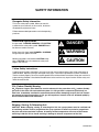
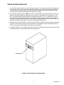
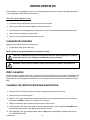
1
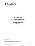
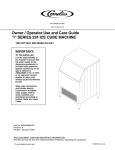
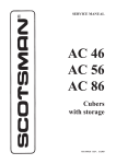
CORNELIUS INC
www.Cornelius.com
Installation Manual
“I” Series 224
Ice Cube Machine
IMPORTANT:
TO THE INSTALLER.
It is the responsibility of
the Installer to ensure that
the water supply to the
dispensing equipment is
provided with protection
against backflow by an air
gap as defined in
ANSI/ASME A112.1.2-1979;
or an approved vacuum
breaker or other such
method as proved effective
by test.
Water pipe connections
and fixtures directly
connected to a potable
water supply shall be
sized, installed, and
maintained according to
Federal, State, and Local
Codes.
Part No. 630460070INS
Revised: May 07, 2014
Revision: B
THIS DOCUMENT CONTAINS IMPORTANT INFORMATION
This Manual must be read and understood before installing or operating this equipment
© CORNELIUS INC; 1998–2014
PRINTED IN U.S.A
TABLE OF CONTENTS
Page
SAFETY INFORMATION . . . . . . . . . . . . . . . . . . . . . . . . . . . . . . . . . . . . . . . . . . . . . . . . . . . .
1
RECOGNIZE SAFETY INFORMATION . . . . . . . . . . . . . . . . . . . . . . . . . . . . . . . . . . 1
UNDERSTAND SIGNAL WORDS . . . . . . . . . . . . . . . . . . . . . . . . . . . . . . . . . . . . . . . 1
FOLLOW SAFETY INSTRUCTIONS . . . . . . . . . . . . . . . . . . . . . . . . . . . . . . . . . . . . 1
CO2 (CARBON DIOXIDE) WARNING . . . . . . . . . . . . . . . . . . . . . . . . . . . . . . . . . . . 1
SHIPPING, STORING, OR RELOCATING UNIT . . . . . . . . . . . . . . . . . . . . . . . . . . 1
GENERAL DESCRIPTION . . . . . . . . . . . . . . . . . . . . . . . . . . . . . . . . . . . . . . . . . . . . . . . . . .
2
FREIGHT DAMAGE CLAIMS PROCEDURE . . . . . . . . . . . . . . . . . . . . . . . . . . . . . .
2
SPECIFICATIONS, ICE CUBER . . . . . . . . . . . . . . . . . . . . . . . . . . . . . . . . . . . . . . . . .
3
INSTALLATION . . . . . . . . . . . . . . . . . . . . . . . . . . . . . . . . . . . . . . . . . . . . . . . . . . . . . . . . . . . .
4
LOCATION OF EQUIPMENT . . . . . . . . . . . . . . . . . . . . . . . . . . . . . . . . . . . . . . . . . . . .
4
PLUMBING CONNECTIONS . . . . . . . . . . . . . . . . . . . . . . . . . . . . . . . . . . . . . . . . . . . .
4
ELECTRICAL . . . . . . . . . . . . . . . . . . . . . . . . . . . . . . . . . . . . . . . . . . . . . . . . . . . . . . . . .
6
INSTALLATION CHECK POINTS. . . . . . . . . . . . . . . . . . . . . . . . . . . . . . . . . . . . . . . . .
6
START-UP AND CHECK OUT . . . . . . . . . . . . . . . . . . . . . . . . . . . . . . . . . . . . . . . . . . .
7
OWNER-OPERATOR . . . . . . . . . . . . . . . . . . . . . . . . . . . . . . . . . . . . . . . . . . . . . . . . . . . . . . .
8
CLEANING PROCEDURES . . . . . . . . . . . . . . . . . . . . . . . . . . . . . . . . . . . . . . . . . . . . .
8
PREP-CLEANING . . . . . . . . . . . . . . . . . . . . . . . . . . . . . . . . . . . . . . . . . . . . . . . . . . . . .
8
CLEANING THE WATER SYSTEM AND EVAPORATOR . . . . . . . . . . . . . . . . . . . .
8
SANITIZING PROCEDURES . . . . . . . . . . . . . . . . . . . . . . . . . . . . . . . . . . . . . . . . . . . .
9
DUMP CYCLE . . . . . . . . . . . . . . . . . . . . . . . . . . . . . . . . . . . . . . . . . . . . . . . . . . . . . . . . .
10
CIRCUIT BOARD SETTING . . . . . . . . . . . . . . . . . . . . . . . . . . . . . . . . . . . . . . . . . . . . .
11
ADJUSTING BRIDGE THICKNESS . . . . . . . . . . . . . . . . . . . . . . . . . . . . . . . . . . . . . .
12
HARVEST CONTROL . . . . . . . . . . . . . . . . . . . . . . . . . . . . . . . . . . . . . . . . . . . . . . . . . .
12
FULL BIN CONTROL . . . . . . . . . . . . . . . . . . . . . . . . . . . . . . . . . . . . . . . . . . . . . . . . . . .
12
LIST OF FIGURES
FIGURE 1. INSTALLATION . . . . . . . . . . . . . . . . . . . . . . . . . . . . . . . . . . . . . . . . . . . . .
4
FIGURE 2. CUBER INSTALLATION . . . . . . . . . . . . . . . . . . . . . . . . . . . . . . . . . . . . . .
5
FIGURE 3. SINGLE EVAPORATOR WATER LEVEL . . . . . . . . . . . . . . . . . . . . . . . .
6
FIGURE 4. ELECTRICAL BOX SWITCH PANEL . . . . . . . . . . . . . . . . . . . . . . . . . . .
7
FIGURE 5. FLOW CONTROL WASHER . . . . . . . . . . . . . . . . . . . . . . . . . . . . . . . . . .
10
FIGURE 6. DUMP CYCLE OPTIONS . . . . . . . . . . . . . . . . . . . . . . . . . . . . . . . . . . . . .
11
FIGURE 7. CUBE SEPARATION . . . . . . . . . . . . . . . . . . . . . . . . . . . . . . . . . . . . . . . . .
12
SAFETY INFORMATION
Recognize Safety Information
This is the safety-alert symbol. When you see this
symbol on our machine or in this manual, be alert to
the potentially of personal injury.
Follow recommended precautions and safe operating
practices.
Understand Signal Words
A signal word - DANGER, WARNING, OR CAUTION
is used with the safety-alert symbol. DANGER identifies the most serious hazards.
Safety signs with signal word DANGER or WARNING
are typically near specific hazards.
General precautions are listed on CAUTION safety
signs. CAUTION also calls attention to safety messages in this manual.
DANGER
WARNING
CAUTION
Follow Safety Instructions
Carefully read all safety messages in this manual and on your machine safety signs. Keep safety signs in
good condition. Replace missing or damaged safety signs. Learn how to operate the machine and how to
use the controls properly. Do not let anyone operate the machine without instructions. Keep your machine in
proper working condition. Unauthorized modifications to the machine may impair function and/or safety and
affect the machine life.
CO2 (Carbon Dioxide) Warning
CO2 Displaces Oxygen. Strict Attention must be observed in the prevention of CO2 (carbon dioxide)
gas leaks in the entire CO2 and soft drink system. If a CO2 gas leak is suspected, particularly in a
small area, immediately ventilate the contaminated area before attempting to repair the leak. Personnel exposed to high concentration of CO2 gas will experience tremors which are followed rapidly by
loss of consciousness and suffocation.
Shipping, Storing, Or Relocating Unit
CAUTION: Before shipping, storing, or relocating this Unit, the syrup systems must be sanitized and
all sanitizing solution must be purged from the syrup systems. All water must also be purged from
the plain and carbonated water systems. A freezing ambient temperature will cause residual water
remaining inside the Unit to freeze resulting in damage to internal components of the Unit.
1
630460070INS
GENERAL DESCRIPTION
This section gives the Unit description, theory of operation, and design data for
IMPORTANT: To the user of this manual – This manual is a guide for installing, operating, and maintaining this equipment. Refer to the Table of Contents for page location for detailed information pertaining to questions that arise during installation, operation, service, or maintenance of this equipment.
FREIGHT DAMAGE CLAIMS PROCEDURE
The deliver of your equipment (freight company, distributor, or dealer) is responsible for loss or damage of your
shipment. All claims must be filed with the deliverer of your equipment. Please follow the steps below to determine is your shipment is satisfactory or if a claim must be filed.
1. Check the number of products delivered against the number of products listed on the delivery receipt.
Should the totals not match, have the driver note all error on both copies and both you and the driver sign
and ate said notation.
2. Inspect all cartons for visible damage. Open and inspect as required before the driver leaves and have him
or her note any damage on the receipts. All damaged claims must be inspected within 15 days of delivery.
Notify your carrier immediately if concealed damage is found after delivery.
3. Should concealed damage be found when product is unpacked, retain the packing material and the product
and request an inspection from the deliverer.
4. All claims for loss or damage should be filed at once. Delays in filing will reduce the chance of achieving a
satis factory resolution to the claim.
630460070INS
2
SPECIFICATIONS, ICE CUBER
The following table contains equipment specification information for the Ice Cubers.
MODEL
IACS224
IACS224E50
IWCS224
UNIT
Volts
115
220
115
Phase
1
1
1
Hertz
60
50
60
No. Wires
2+Ground
2+Ground
2+Ground
MIN. CIRCUIT MAX FUSE SIZE (HVAC CIRCUIT BREAKER REQUIRED)
Amps
20
15
20
MAX FUSE SIZE (HVAC CIRCUIT BREAKER REQUIRED)
Amps
20
15
REFRIGERANT
Type
R404A(HP62)
R404A(HP62)
R404A(HP62)
Weight (oz)
13
13
13
Weight (g)
369
369
369
COMPRESSOR
Volts
115
220
115
Phase
1
1
1
Hertz
60
57
60
LRA
37.2
16.1
37.2
RLA
7.1
2.8
7.1
CONDENSER FAN MOTOR (Air-Cooled Systems only) or
AIR CIRCULATION FAN MOTOR (Water-Cooled and Remote Systems only)
Volts
115
220
115
Phase
1
1
1
Hertz
60
50
60
Amps Running 1.4
1.4
.36
Watts
35
35
6
WATER PUMP
Volts
115
220
115
Phase
1
1
1
Hertz
60
50
60
Amps Running .89
.45
.89
HP
1/60
1/50
1/60
3
IWCS224E50
220
1
50
2+Ground
15
15
R404A(HP62)
13
369
220
1
57
16.1
2.8
220
1
50
.17
5
220
1
50
.45
1/50
630460070INS
INSTALLATION
This section covers unpacking and inspection, selecting location, installing Unit, preparing for operation, and
operation. Installation and start-up of the equipment should be performed by the distributor or the dealer’s
professional staff.
LOCATION OF EQUIPMENT
For maximum performance the location should be away from heat sources such as ovens, direct sunlight, hot
air discharge, etc.
To reduce cost of maintenance and loss of efficiency, avoid placing air-cooled equipment in areas where grease,
flour and other airborne contaminants are present. Allow a minimum of 6” (15.24 cm) clearance at the front for
proper air circulation. Restricted air circulation will affect the efficiency and required maintenance of the product.
IMPORTANT: Never operate your equipment in room temperature below 50_F (10 _C) OR ABOVE
100_F(38_C). Should the location of your product ever be exposed to freezing temperatures, it must be
shut down and winterized.
AIR COOLED
WATER COOLED
CONDENSER
WATER IN
SHUT-OFF VALVE
EVAPORATOR
WATER IN
ELECTRICAL CORD
TO OUTLET
ELECTRICAL CORD
TO OUTLET
WATER FILTER
DUMP VALVE
DRAIN TUBE
CONDENSER
WATER OUT
BIN DRAIN TUBE
BIN DRAIN TUBE
FLOOR DRAIN
DUMP VALVE
DRAIN TUBE
FLOOR DRAIN
FIGURE 1. INSTALLATION
PLUMBING CONNECTIONS
1. All plumbing lines and connections must conform to local and national plumbing codes.
2. Line shut-off valves must be located in supply water lines for cuber and condenser if product is watercooled. Water supply to water-cooled condenser must include a stand-pipe to prevent “water hammer”.
3. Should your local water supply quality require the installation of a water filter system, consult your local distributor or dealer for proper size required.
4. Water supply pressure must not be lower the 20 PSI (1.37 BAR), nor should it exceed 120 PSI (8.16
BAR).
IMPORTANT: water filters larger than 5 microns do not give proper protection. Water pressures above
80 PSI (5.44 BAR) will destroy the filter.
4
630460070INS
FIGURE 2. CUBER INSTALLATION
5
630460070INS
ELECTRICAL
1. All wiring and connections must conform to national and local electrical codes.
2. Wire size and circuit protection must conform to specifications and cuber must be on a separate electrical
circuit.
3. Cuber must be grounded for the safety requirements.
4. A manual disconnect in a convenient location to the cuber must be installed.
INSTALLATION CHECK POINTS.
IMPORTANT: For the Ice Cube Machine to operate properly, the front and back panels must be in place
on the machine. When the Ice Cube Machine is operated without the panels in place, airflow across
the condenser coils is affected, causing pressure variations. These pressure variations can result in
low or a failed ice harvest.
1. Has bin and cuber been leveled and sanitized?
2. Does electrical and plumbing meet code requirements?
3. Check correct operation water level in the water pan.
4. Are drain lines separate and vented?
5. Is there 6” clearance in the front of the machine for proper air circulation?
6. Does the ice harvest switch move freely, and does the float valve shut off incoming water to water pan?
7. Vigorously rub the stainless steel water plate(s), on top of the evaporator(s), with scotch-brite pad to remove any oxidation and improve the ability of the water to properly track across plain.
OPERATING WATER LEVEL
SINGLE EVAPORATOR
1.5”
WATER PAN RIGHT SIDE VIEW
630460070INS
FIGURE 3. SINGLE EVAPORATOR WATER LEVEL
6
START-UP AND CHECK OUT
1. Turn the cuber’s power switch to the clean (pump only) position. The water pump only should be operational. Check for an even, steady flow of water over the evaporator top extrusion and down over evaporator
surface. Check that all ports of the water distribution tube are open for even water discharge. The water
pan should refill and the float should stop the incoming water supply.
2. Place the cuber’s power switch in ON position. After a 2 second delay the compressor will start. The condenser fan will operate when the condenser sensor signals the circuit board that its temperature is 100
(38_ C). The water pump will operate when the evaporator cools to 25_F (3.9_ C). Depress the manual
harvest switch located on the circuit board. The fan motor will stop and the water dump valve will open. in
3 seconds the hot gas solenoid will open and 15 seconds after depressing the manual harvest switch, the
water pump will stop and the dump valve will close terminating the dump cycle.
3. Hold the ice harvest switch open for a maximum of 30 seconds; the product should shut down. Release the
ice harvest switch. When the switch closes, there will be a 2 second delay, and the compressor will start
and the start-up process should begin for the next ice making mode.
4. If all product operation are as stated, allow product to operate and product one slab of ice, then discard the
ice. Allow the product to continue operation to fill the storage bin.
ON
OFF
CLEAN
DUMP
VALVE
POWER SWITCH
FIGURE 4. ELECTRICAL BOX SWITCH PANEL
7
630460070INS
OWNER-OPERATOR
The installation is not complete until you are sure the owner-operator understands the cuber operation and his
or her responsibility of preventative maintenance.
Does the owner-operator know:
1. Location of electrical disconnect switch and water shut-off valves?
2. How to start and/or shut down the product, clean and sanitize it.?
3. Bin full operation and reset operation of high pressure cutout (water-cooled and remote products only.)?
4. How to clean the condenser and fan blade?
5. Whom to call for product information and/or service?
CLEANING PROCEDURES
Approved ice machine cleaners by brand names:
S Calgon Nickel Safe (green color only)
NOTE: Failure to use approved product will void the warranty.
CAUTION: Ice Machine cleaners are acidic-based chemicals. Before beginning any cleaning
of the cuber, the ice in the storage bin or dispenser must be removed.
WARNING: When using any chemical rubber gloves and eye protection should be worn.
PREP-CLEANING
Use full-strength ice machine cleaner on a coarse-surface cloth material (such as terry cloth) and wipe down the
inside wall of the evaporator area, the evaporator top. If the water distributor tube has heavy scale build-up, remove and soak in a full-strength ice machine clean ( or exchange the tube and clean the scaled tube at a later
date).
CLEANING THE WATER SYSTEM AND EVAPORATOR
1. Set the switch to CLEAN and allow the ice on the evaporator to release the melt away.
2. Remove all ice from the storage bin.
3. Add 3 oz. for a single evaporator of “Calgon Nickel-Safe” ice machine cleaner directly into the water pan.
Set switch to CLEAN, circulate for a maximum of 15 minutes.
4. Depress and hold the dump switch to allow the cleaner to drain away.
5. Fill the water pan with clean fresh water, circulate for approximately 3 minute. Depress the DUMP switch
and allow the water to drain away. Repeat this procedure 3 times.
6. After third rinse cycle, place product power switch in ON position. Allow product to produce one slab of
ice—DISCARD THE ICE.
8
630460070INS
7. When clean cycle is complete, return cuber to normal operating mode.
NOTE:
Please take not of the following:
S Ice machines should only be cleaned when needed, not by a timed schedule of every 60 days, etc.
S Should your ice machine require cleaning more than twice a year, consult your distributor or dealer about
proper water treatment.
ON
OFF
CLEAN
DUMP
VALVE
POWER SWITCH
SANITIZING PROCEDURES
1. Add 1/4 ounce (7.08 g) sodium hypochlorite solution (common liquid laundry bleach) to the water pan and
allow the pump to circulate the solution for 5 minutes. You may also use a commercial sanitizer such as
Calgon Ice Machine Sanitizer following the directions on the product label.
2. Turn the product power switch off and depress the dump switch to drain the water pan.
3. To sanitize the bin and other surface areas, use 1 ounce of liquid bleach per gallon of water and wipe all
areas with solution. Or use a commercial sanitizer.
4. Place the product power switch in the ice position. Discard the first batch of ice produced.
5. Cleaning and sanitizing are now complete, Product may be returned to normal service.
9
630460070INS
OPERATING WATER LEVEL
SINGLE EVAPORATOR
DUMP CYCLE
1. With the proper water level in the water pan, start the water
pump to circulate the water. Check that the float will return
water level to original setting and stop the inlet water.
2. There is flow washer in the inlet side of the float assembly that
will control inlet eater pressure from 50/120 PSI (3.4/8.16 Bars). This
will prevent float flutter. In low water pressure conditions, 20 PSI
(1.37 Bars) or less, the flow washer may have to be removed from
the float assembly for proper fill volume.
1.5”
WATER PAN RIGHT SIDE VIEW
FLOW CONTROL WASHER
FLAT SIDE UP
FIGURE 5. FLOW CONTROL WASHER
Push the manual DUMP switch - allow dump action to drain the water pan. When you release the momentary
switch, the pump will stop and the float will return the water level back to its original setting and shut off the water supply.
3. You have the option of selecting dump cycle intervals of:
S
every cycle
S
every 3rd cycle
S
every 7th cycle
Remember: The higher the mineral content in the water supply the more often it will be required to dump the
water and/or clean the product if proper water treatment is not used.
630460070INS
10
CIRCUIT BOARD SETTING
Figure 6 shows the setting of circuit board. There are dump cycle dip switch (S3) and curtain selection dip
switch (SW4) in the circuit board. Even though no water curtain equipped in IACS224 and IWCs224, “single curtain connection” on SW4 need to be selected.
External Error LED
Connection
Harvest Voltage Set point pins 2
and 3 Factory setting @ 1.224 V
Condenser Sensor
Suction Line Sensor
RD
Error
Bridge thickness pot.
1
2
3
S3-1
OFF
ON
OFF
Dump
S3-2
OFF Dump Every Harvest (FACTORY SETTING AS RECEIVED)
OFF Dump Every Third Harvest
ON Dump Every Seventh Harvest
On
GR
S3–2
S3–1
Off
Fan
GR
ON
1
S3–1
2
S3–1
S3–2
Dump Cycle Dip Switch
Comp.
OFF
ON
On
1 2 3
S3–2
Pump
Gear
OFF
ON
3
S3–1
Off
S3–2
OFF
ON
S3–1
GR
Micro Processor
GR
Curtain
Selection
Switch
S3–2
OFF
Gas
GR
1
Water Curtain
Dip Switch
YL
2
ON
SW4
4
Bin
Switches
YL
3
OFF
YL
ON
4
YL
SW4
5
OFF
Stack
Triac
Transformer
In
Out
Com
ON
SW4
6
OFF
SINGLE CURTAIN
4 Curtain Switch Connected To Any
Bin Connector (J4–J7) (FACTORY
SETTING AS RECEIVED)
DUAL CURTAIN
5 Curtain Switch Must Be Connected To
J4 and J5, J6, J7.
FOUR CURTAIN
6 Curtain Switch Must Be Connected
To J4, J5, J6 and J7)
FIGURE 6. DUMP CYCLE OPTIONS
11
630460070INS
ADJUSTING BRIDGE THICKNESS
TOP ROW
3/8’ - 5/8”
DIMPLE
CENTER
1/8” BRIDGE
For optimum ice production and maximum cube separation, the ice connecting the individual
cubes should be a minimum of 1/8” (.32 cm) thick at the center area of the ice waffle.
BRIDGE 1/8” (0.32 CM)
It is normal for the Ice Bridge to be slightly thicker at the bottom and taper off in a slight wedge
pattern at the top. The top row of cubes must have a complete pattern of ice on all four sides
and the back wall.
BOTTOM 2
ROWS
3/16” - 1/4”
BRIDGE
FIGURE 7. CUBE SEPARATION
REMEMBER: When you operate the product with the panels off during testing the additional heat at the top of
the evaporator will cause thinner ice at the top than when the panels are in place.
Should a different thickness of the bridge be desired, it will be required to adjust the ice thickness “POT”, located on the circuit board, as follows:
1. Thinner Bridge - Turn the ice thickness “pot” adjustment screw Ø CW one full turn.. Allow two cycles before determining if additional adjustments are required.
2. Thicker Bridge - turn the ice thickness “pot” adjustment screw Ù CCW on full turn. Allow two cycles before
determining if additional adjustments are required.
NOTE: Never judge the thickness of the ice from the first batch of ice produced - the first cycle is a
balance cycle. Always wait for the second cycle before making and adjustments.
HARVEST CONTROL
An ice harvest switch bar is used to control the harvest cycle. It is operated by the movement of the ice from
evaporator. The momentary opening of the ice harvest switch terminates the ice machine’s harvest cycle.. As
the ice harvest bar swings closed, the ice machine returns into the freezing cycle.
FULL BIN CONTROL
A bin thermostat is provided to control the level of the ice in the storage bin. When the storage bin is full, the bin
thermostat tube equipped inside the storage bin will sense a low temperature which causes the bin thermostat
to switch to it “close” position. The ice machine will complete the cycle and shut off.
The ice machine remains off until sufficient ice is removed from the storage bin allowing the bin thermostat tube
to warm up. As the bin thermostat tube senses a warm temperature which causes the bin thermostat to switch
back to its “open” position, the ice machine starts to make ice.
The setting of bin thermostat can be adjusted by turning the dial on the top of thermostat to”CW” to cold position
or to “CCW” to warm position. In the mid-range position the bin thermostat will close at about 42_F.
630460070INS
12
THIS PAGE LEFT BLANK INTENTIONALLY
CORNELIUS INC.
www.Cornelius.com