1
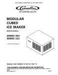
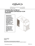
SERIES 322
ICE CUBE MACHINE
Service/Installation
Guide
Part No. 166240008
March 17, 1995
THIS DOCUMENT CONTAINS IMPORTANT INFORMATION
This Manual must be read and understood before installing or operating this equipment
Ó IMI CORNELIUS INC; 1995
PRINTED IN U.S.A
TABLE OF CONTENTS
Page
SAFETY INFORMATION . . . . . . . . . . . . . . . . . . . . . . . . . . . . . . . . . . . . . . . . . . . . . . .
SPECIFICATIONS . . . . . . . . . . . . . . . . . . . . . . . . . . . . . . . . . . . . . . . . . . . . . . . . . . . . .
1
3
ELECTRICAL . . . . . . . . . . . . . . . . . . . . . . . . . . . . . . . . . . . . . . . . . . . . . . . . . . . . .
PLUMBING CONNECTIONS . . . . . . . . . . . . . . . . . . . . . . . . . . . . . . . . . . . . . . . .
UNPACKING . . . . . . . . . . . . . . . . . . . . . . . . . . . . . . . . . . . . . . . . . . . . . . . . . . . . . . . . . .
LEVELING . . . . . . . . . . . . . . . . . . . . . . . . . . . . . . . . . . . . . . . . . . . . . . . . . . . . . . . . . . . .
UNIT LOCATION . . . . . . . . . . . . . . . . . . . . . . . . . . . . . . . . . . . . . . . . . . . . . . . . . . . . . .
UNIT SET--UP . . . . . . . . . . . . . . . . . . . . . . . . . . . . . . . . . . . . . . . . . . . . . . . . . . . . . . . . .
MAKE ELECTRICAL POWER SUPPLY CONNECTION . . . . . . . . . . . . . . . . . . . . .
3
3
3
4
4
4
5
MAKE PLUMBING CONNECTIONS . . . . . . . . . . . . . . . . . . . . . . . . . . . . . . . . . . . . . .
FOR WATER COOLED UNITS . . . . . . . . . . . . . . . . . . . . . . . . . . . . . . . . . . . . . .
DRAIN . . . . . . . . . . . . . . . . . . . . . . . . . . . . . . . . . . . . . . . . . . . . . . . . . . . . . . . . . . . . . . . .
DRAIN CONNECTION INSTALLATION INSTRUCTIONS. . . . . . . . . . . . . . . . . . . .
WATER LEVEL RESERVOIR . . . . . . . . . . . . . . . . . . . . . . . . . . . . . . . . . . . . . . . . . . . .
STARTING THE UNIT . . . . . . . . . . . . . . . . . . . . . . . . . . . . . . . . . . . . . . . . . . . . . . . . . .
5
5
6
6
6
7
INSTALLATION INSTRUCTIONS FOR MOUNTING ON DRINK DISPENSERS
CHECKOUT PROCEDURE FOR HARVEST BIN SWITCHES . . . . . . . . . . .
ADJUSTMENT PROCEDURE FOR HARVEST BIN SWITCHES. . . . . . . . .
SANITIZING AND CLEANING PROCEDURE . . . . . . . . . . . . . . . . . . . . . . . . . . . . . .
WATER TREATMENT . . . . . . . . . . . . . . . . . . . . . . . . . . . . . . . . . . . . . . . . . . . . . . . . . .
WINTER STORAGE . . . . . . . . . . . . . . . . . . . . . . . . . . . . . . . . . . . . . . . . . . . . . . . . . . .
CLEANING THE AIR COOLED CONDENSER COIL . . . . . . . . . . . . . . . . . . . . . . . .
8
8
8
9
10
10
10
OPERATING CHARACTERISTICS . . . . . . . . . . . . . . . . . . . . . . . . . . . . . . . . . . . . . . .
REFRIGERATION AND WATER SYSTEM MODEL AC322 . . . . . . . . . . . . . . . . . .
REFRIGERATION AND WATER SYSTEM MODEL WC322 . . . . . . . . . . . . . . . . .
DUMP CYCLE . . . . . . . . . . . . . . . . . . . . . . . . . . . . . . . . . . . . . . . . . . . . . . . . . . . . . . . . .
ADJUSTING BRIDGE THICKNESS . . . . . . . . . . . . . . . . . . . . . . . . . . . . . . . . . . . . . .
TOTAL ICE CAPACITY . . . . . . . . . . . . . . . . . . . . . . . . . . . . . . . . . . . . . . . . . . . . . . . . .
11
12
13
14
15
15
ICE PRODUCTION CHECK . . . . . . . . . . . . . . . . . . . . . . . . . . . . . . . . . . . . . . . . . . . . .
LED INDICATORS . . . . . . . . . . . . . . . . . . . . . . . . . . . . . . . . . . . . . . . . . . . . . . . . . . . . .
CIRCUIT BOARD DIAGNOSIS . . . . . . . . . . . . . . . . . . . . . . . . . . . . . . . . . . . . . . . . . .
COMPONENT FUNCTION . . . . . . . . . . . . . . . . . . . . . . . . . . . . . . . . . . . . . . . . . . . . . .
TEST PLUG . . . . . . . . . . . . . . . . . . . . . . . . . . . . . . . . . . . . . . . . . . . . . . . . . . . . . . . . . . .
SENSORS . . . . . . . . . . . . . . . . . . . . . . . . . . . . . . . . . . . . . . . . . . . . . . . . . . . . . . . . . . . .
RESET OPERATION . . . . . . . . . . . . . . . . . . . . . . . . . . . . . . . . . . . . . . . . . . . . . . . . . . .
15
16
18
19
19
19
19
EVAPORATOR SWITCHES . . . . . . . . . . . . . . . . . . . . . . . . . . . . . . . . . . . . . . . . .
HARVEST SAFETY TERMINATION . . . . . . . . . . . . . . . . . . . . . . . . . . . . . . . . .
VOLTAGE CHECKS . . . . . . . . . . . . . . . . . . . . . . . . . . . . . . . . . . . . . . . . . . . . . . . . . . . .
EVAPORATOR PROXIMITY SWITCH . . . . . . . . . . . . . . . . . . . . . . . . . . . . . . . .
VOLTAGE SELECTOR SWITCH . . . . . . . . . . . . . . . . . . . . . . . . . . . . . . . . . . . . . . . . .
SENSOR [THERMISTOR] DIAGNOSIS . . . . . . . . . . . . . . . . . . . . . . . . . . . . . . . . . .
SENSORS . . . . . . . . . . . . . . . . . . . . . . . . . . . . . . . . . . . . . . . . . . . . . . . . . . . . . . . .
19
19
19
19
20
20
20
THERMOSTATIC EXPANSION VALVES . . . . . . . . . . . . . . . . . . . . . . . . . . . . . . . . . .
STARVING TXV - PRODUCT SYMPTOMS . . . . . . . . . . . . . . . . . . . . . . . . . . .
20
21
i
166240008
TABLE OF CONTENTS (cont’d)
Page
FLOODING TXV - PRODUCT SYMPTOMS . . . . . . . . . . . . . . . . . . . . . . . . . . .
WATER REGULATING VALVE . . . . . . . . . . . . . . . . . . . . . . . . . . . . . . . . . . . . . . . . . . .
21
21
SERVICE STEM VALVES . . . . . . . . . . . . . . . . . . . . . . . . . . . . . . . . . . . . . . . . . . . . . . .
MOISTURE CONTAMINATION . . . . . . . . . . . . . . . . . . . . . . . . . . . . . . . . . . . . . . . . . .
COMPRESSOR CONTACTOR . . . . . . . . . . . . . . . . . . . . . . . . . . . . . . . . . . . . . . . . . .
COMPRESSOR & STARTING COMPONENT CHECK-OUT PROCEDURE . . . .
RELAY . . . . . . . . . . . . . . . . . . . . . . . . . . . . . . . . . . . . . . . . . . . . . . . . . . . . . . . . . . .
CAPACITORS . . . . . . . . . . . . . . . . . . . . . . . . . . . . . . . . . . . . . . . . . . . . . . . . . . . . .
COMPRESSOR . . . . . . . . . . . . . . . . . . . . . . . . . . . . . . . . . . . . . . . . . . . . . . . . . . .
22
22
23
23
23
24
24
LEAK DETECTION . . . . . . . . . . . . . . . . . . . . . . . . . . . . . . . . . . . . . . . . . . . . . . . .
SYSTEM EVACUATION & RECHARGING . . . . . . . . . . . . . . . . . . . . . . . . . . . . . . . .
SELF-CONTAINED PRODUCTS . . . . . . . . . . . . . . . . . . . . . . . . . . . . . . . . . . . . . . . . .
CONDENSER FAN CYCLING CONTROL . . . . . . . . . . . . . . . . . . . . . . . . . . . . . . . . .
HIGH PRESSURE SAFETY SWITCH . . . . . . . . . . . . . . . . . . . . . . . . . . . . . . . . . . . .
WARRANTY . . . . . . . . . . . . . . . . . . . . . . . . . . . . . . . . . . . . . . . . . . . . . . . . . . . . . . . . . .
25
25
25
27
27
28
166240008
ii
SAFETY INFORMATION
Recognize Safety Information
This is the safety-alert symbol. When you see this
symbol on our machine or in this manual, be alert to
the potentially of personal injury.
Follow recommended precautions and safe operating
practices.
Understand Signal Words
A signal word - DANGER, WARNING, OR CAUTION
is used with the safety-alert symbol. DANGER identifies the most serious hazards.
Safety signs with signal word DANGER or WARNING
are typically near specific hazards.
General precautions are listed on CAUTION safety
signs. CAUTION also calls attention to safety messages in this manual.
DANGER
WARNING
CAUTION
Follow Safety Instructions
Carefully read all safety messages in this manual and on your machine safety signs. Keep safety signs in
good condition. Replace missing or damaged safety signs. Learn how to operate the machine and how to
use the controls properly. Do not let anyone operate the machine without instructions. Keep your machine in
proper working condition. Unauthorized modifications to the machine may impair function and/or safety and
affect the machine life.
CO2 (Carbon Dioxide) Warning
CO2 Displaces Oxygen. Strict Attention must be observed in the prevention of CO2 (carbon dioxide)
gas leaks in the entire CO2 and soft drink system. If a CO2 gas leak is suspected, particularly in a
small area, immediately ventilate the contaminated area before attempting to repair the leak. Personnel exposed to high concentration of CO2 gas will experience tremors which are followed rapidly by
loss of consciousness and suffocation.
Shipping, Storing, Or Relocating Unit
CAUTION: Before shipping, storing, or relocating this Unit, the syrup systems must be sanitized and
all sanitizing solution must be purged from the syrup systems. All water must also be purged from
the plain and carbonated water systems. A freezing ambient temperature will cause residual water
remaining inside the Unit to freeze resulting in damage to internal components of the Unit.
3/17/95
1
166240008
THIS PAGE LEFT BLANK INTENTIONALLY
166240008
2
3/17/95
SPECIFICATIONS
322 SERIES
15.00
C
22.00
A
7.00
AIR IN
E
23.50
21.00
D
5.00
23.50
FRONT
14.75
F
11.25
1.00
2.00
.75
2.75
2.25
OPENING
16.38
5.00
6 FT ELECTRICAL
CORD
B
22.00
NOTE: MUST USE 20 AMP RECEPTACLE
A
B
C
D
E
F
WATER INLET
PUMP OUT DRAIN
ELECTRICAL CONNECTION
CONDENSATE DRAIN
CONDENSER (WATER OUT)(W/C ONLY)
CONDENSER (WATER IN)(W/C ONLY)
ill 140
Net Weight . . . . . . . . . . . . . . . . . . . . . . . . . . . . . . . .
122 lbs.
Shipping Weight . . . . . . . . . . . . . . . . . . . . . . . . . . .
138 lbs.
Compressor Copeland . . . . . . . . . . . . . . . . . . . . . .
5,300/BTU
Refrigerant . . . . . . . . . . . . . . . . . . . . . . . . . . . . . . . .
R--22
Electrical
Freeze Cycle Amps Draw . . . . . . . . . . . . . . . . . . .
8.0
Time Delay Fuse Retains (amps) . . . . . . . . . . . . .
20.0
Minimum Circuit Ampacity (amps) . . . . . . . . . . . .
20.0
Power Supply (Single Phase) . . . . . . . . . . . . . . . .
115V/60 Hz
Plumbing Connections
Inlet Water Supply . . . . . . . . . . . . . . . . . . . . . . . . . .
Max. pressure 50 PSI 3/8”SAE MFL Ftg
Bin Drain . . . . . . . . . . . . . . . . . . . . . . . . . . . . . . . . . .
Through Bin
Waster Water (from water cooled models) . . . . .
Two 3/8 in. SAE MFL Fittings
Pump Out Drain Connection . . . . . . . . . . . . . . . . .
1/2 in. ID Tubing
UNPACKING
1. Uncrate machine and/or bin by removing the staples from around the bottom of cardboard crate and lift off.
2. Remove bolts fastening the crate skid to the bottom of the unit. If auxiliary legs have been purchased for
the bin, they should be installed at this time.
166240008
3/17/95
3
LEVELING
1. 1. If legs are used, adjust the leveling legs of the storage bin until the unit is level and all four(4) legs are
in sold contact with the floor. Leveling is very important to obtain proper draining and to maintain the proper
level in the water pump pan of the ice cuber.
Note: If the bin is to be installed flush to the floor, the bin must be sealed to floor with an approved
mastic such as Dow R.T.V. #732, 734, or G.E. #102, 108. This is an N.S.F. requirement and is the responsibility of the installer.
UNIT LOCATION
1. Allow at least a minimum of six inches at the rear and side of the ice machine for proper air RHP circulation.
2. This unit has been designed to be installed in an indoor location which is clean and which can be adequately ventilated. The air and water temperatures should never exceed 100 F or fall below 50 F. (Temperatures
above 100 F will cut the ice making capacity below an economical level. Temperatures below 50 F will
cause a malfunction of thermostatic sensors).
3. The unit should be located where air circulation is not restricted. The unit should not be located near a
kitchen grill. Air which contains grease vapors will deposit grease on the condenser. The condenser should
always be kept clean.
UNIT SET--UP
1. Take off front panel of machine and remove hardware bag and service manual envelope.
2. Mount the ice maker to the top of the ice storage bin or adapter in the proper position over the ice drop
opening. The ice maker must then be sealed both on the outside and the inside bottom edges with an approved N.S.F. mastic such as Dow R.T.V. #732, 734, or G.E. R.T.V. #102, 108 (Diagram 2). This is an
N.S.F. requirement and the responsibility of the installer.
3. Remove shipping tape from evaporator curtains.
166240008
4
3/17/95
Diagram 2
MAKE ELECTRICAL POWER SUPPLY CONNECTION
Requirements: 115V/60 Hz 1 ph., 230V/60 Hz. 1 ph., or 220V/50 Hz. 1 ph when used.
Refer to serial plate for minimum circuit ampacity and maximum time delay fuse size.
All wiring must conform to national and local electrical codes.
MAKE PLUMBING CONNECTIONS
Water supply -- (install per local codes) (See diagram 3).
The water inlet connection to the unit is a 3/8”male flare connection located at the rear of the ice machine.
WARNING: If the water pressure exceeds 50 pounds, a water pressure regulator should be
installed in the water inlet line between the water shut--off valve and the strainer.
Install a reducer fitting on the shut--off valve to accommodate the water stainer, which is supplied with each ice
machine and MUST be used. This is very important for cleaning. Connect either 3/8”or 1/2”copper tubing between the water inlet fitting of the ice machine and the water strainer.
For water cooled units
Two water inlet connections are provided. One for the ice making (evaporator) section which is located on the
back of the machine and is a 3/8”flared connection. The other is for the water cooled condenser.
The reason for the separate water inlet connections is that some installations use a water tower for cooling the
water used in the water cooled condenser and some installations use treated water (filtered) for the ice making
inlet water connections. Be sure to install water line (incoming) to the 3/8”male flare connection on the back of
the unit that supplies water to the water regulating valve inside. The setting of the water regulating valve from
the factory should be 200 pounds for R--22 units. NOTE: Always flush out water lines before starting unit. Adjustments, if necessary, should be done at installation.
166240008
3/17/95
5
NOTE: TAKE CARE NOT TO
KINK OR COLLAPSE VINYL
TUBING.
POWER CORD
(322 UNIT ONLY)
STRAINER WATER
(NON-DIRECTIONAL)
SERVICE VALVES
50 PSI MAX. WATER PRESSURE
WATER SUPPLY ICE MAKING
WATER SUPPLY WC CONDENSER
DUMP VALVE
DRAIN
VENT
DRAIN WC
CONDENSER
DRAIN
PIPE
DRAIN
CONDENSATION
VENT
OPEN TRAPPED OR VENTED
DRAIN
BIN
DRAIN
TYPICAL INSTALLATION: ALL ELECTRICAL & PLUMBING
MUST BE DONE PER LOCAL CODES.
ill018
DRAIN
Provide a suitable trapped open drain as close as possible to the area where the ice maker is going to be
installed. This may be an existing floor or a 1--1/4”trapped open drain. Two separate drain lines are required for
air cooled units, one for the storage bin and one for the dump valve drain hose.
An additional separate drain line will be required for water cooled units from the outlet of the condenser coil to
the drain. Run all gravity drain lines with a good fall to the open drain.
All Plumbing Must Be Installed In Accordance With Local Codes.
NOTE: In some cases it may be necessary to insulate the water supply line and drain line. Condensate
dripping to the floor can cause serious staining of carpets or hardwoods.
DRAIN CONNECTION INSTALLATION INSTRUCTIONS.
Taking care not to kink or collapse vinyl tubing at any point, route tubes to any open, trapped or vented floor
drain. Run tubing to drain separately. Do not tee any drain hoses together. Add drain tubing required to reach
floor drain.
WATER LEVEL RESERVOIR
The Float Valve is mounted in a fixed position thru it’s mounting bracket to maintain the proper water level in the
water reservoir. For the 300 & 322 series units the bracket is mounted thru the bottom hole of the bracket.
166240008
3/17/95
6
SUPPORT WEB
ADJUST HERE
RESERVOIR
1/4”
WATER LEVEL
FLOAT ASSEMBLY
ILL023
WARNING: Ice maker will not operate properly when water supply temperature is below
50_F. or above 100_F. Water supply flowing pressure must not exceed 50 PSI.
STARTING THE UNIT
After the ice cuber has been unpacked and leveled and all plumbing and electrical connections have been
made, start the unit, and check for proper operation.
A cuber has three separate circuits: the water circuit, the refrigerant circuit and the electrical circuit.
1. Start checking the water circuit by making sure that there are not thread of flare joint leaks, either outside
the unit or in the compressor section. Next check the water flow over the evaporator and make sure that all
holes in the water distributor are open, (See Diagram 5) and that there is no undue splash or loss of water
into the ice bin.
3/17/95
7
166240008
Also check to see if the float valve is functioning properly and the correct water level is being maintained. Adjust
if necessary.
2. Check the refrigerant circuit by making sure that the condenser fan is running. (This will be evident by air
noise) Is the compressor running? (Feel the casing for vibration). Is the evaporator getting cold?
3. Check bin--harvest switch operation. )See procedure in manual).
WATER
DISTRIBUTOR
HOLES
ILL025
INSTALLATION INSTRUCTIONS FOR MOUNTING ON DRINK DISPENSERS
For mounting ice machine on to an ice/drink dispenser you should have the proper install kit.
Checkout Procedure For Harvest Bin Switches
Turn on the ice machine and move the evaporator curtain(s) away from the evaporator(s). The ice machine
should then shut--off in approximately 10 seconds. (See detail A & B).
Slowly let the evaporator curtain(s) move back toward the evaporator(s) until the bottom edge of the curtain(s)
is at least at the bent edge of the water reservoir or closer to the evaporator. With the curtain(s) at that position,
the machine should start. (See detail C).
DETAIL ”B”
ACORN NUT
CURTAIN EDGE
SENSOR
THERMOWELL
MAGNET
PROXIMITY
SWITCH
EVAPORATOR
CURTAIN
ACORN NUT
WATER
RESERVOIR
ill 021
BOTTOM
EDGE OF
EVAPORATOR
CURTAIN
DETAIL ”C”
DETAIL ”A”
Adjustment Procedure For Harvest Bin Switches.
If adjustment is necessary, loosen acorn nuts and move proximity switch closer to the curtain(s) and make sure
the curtain is properly mounted. (See detail A).
166240008
3/17/95
8
Re--check per above procedure.
SANITIZING AND CLEANING PROCEDURE
1. Remove front panel to gain access to the on--off clean switch.
2. Push switch to “Clean”and allow the ice on the evaporator to release or melt away.
ELECTRICAL BOX
SWITCH, DUMP
SWITCH, ON/OFF/CLEAN
WATER PUMP
ILL063
3. Remove ice from storage bin.
4. If lime scale is present add 2 oz. of “Lime--A--Way”or “Calgon NickelSafe Ice Machine Cleaner”directly into
water reservoir. Circulate for not longer than 10 minutes. Depress dump valve switch on side of control box
and allow cleaner or sanitizer to drain away. Allow float valve to fill reservoir with clean, fresh water. Circulate for approximately 1 minute. Depress dump valve switch and allow water to drain away. Repeat three
times.
CAUTION: All ice machine cleaner must be flushed out of the system before the sanitizing
solution is used in Step 5. The reaction of the two chemical can cause hazardous gases to be
generated.
5. Pour 1/4 oz. of household bleach into the water reservoir and circulate for 10 minutes to sanitize the circulating water system including the evaporator, pump, distributor and all interconnecting vinyl tubing. Depress
dump valve switch on side of control box and allow cleaner or sanitizer to drain away. Allow float valve to fill
reservoir with clean, fresh water. Circulate for approximately 1 minute. Depress dump valve switch and allow water to drain away. Repeat three times.
6. Mix sanitizing solution of 1/2 oz. household bleach to one gallon of water. This mixture will provide 200 ppm
chlorine. Using a non--metallic bristle brush, scrub the following:
A.
Inside surface of the ice bin including top and door.
B.
Inside surface of the ice maker to include evaporator section in the ice machine including the top, front
panel and evaporator splash curtain.
C.
Make sure splash curtain is correctly positioned.
7. Depress dump valve switch and allow cleaner to drain away. Allow float valve to fill reservoir with clean,
fresh water. Circulate for approximately 1 minute. Depress dump valve switch and allow water to drain
away. Repeat three times.
8. Push switch from “clean”to “on”position.
9. Replace front panel.
3/17/95
9
166240008
WATER TREATMENT
Depending on the water source for the ice maker, water treatment may be necessary to prevent calcium or lime
scale deposits, bad taste and odor, chlorine problems, as well as slime growth. If these conditions exist, contact
your Cornelius Distributor or Dealer for information on water treatment systems Cornelius offers.
WINTER STORAGE
If the unit is to be stored in an area where the temperature will drop below freezing, it is most important that all
water lines be drained to prevent them from freezing and possible rupture.
To blow out the waterline, disconnect the water supply at the cabinet inlet and use air pressure to force the water into the water reservoir pan. This can then be removed from the water pan.
CLEANING THE AIR COOLED CONDENSER COIL
In order to produce at full capacity, the refrigeration condenser must be kept clean. The frequency of cleaning
will be determined by surrounding conditions. A good maintenance plan calls for an inspection at least every two
months.
CAUTION: Condenser cooling fins are sharp. Use care when cleaning.
Clean the air condenser coil from the back of the machine with a vacuum cleaner. Remove all the accumulated
dust, lint, and dirt.
166240008
10
3/17/95
AVERAGE OPERATING CHARACTERISTICS
AC322
IP Units
FREEZE CYCLE
HARVEST CYCLE
AMBIENT
TEMP
_F
WATER
TEMP
_F
HEAD
PRESSURE
Psig
SUCTION
PRESSURE
Psig
CYCLE
TIME
Min:Sec
HEAD
PRESSURE
Psig
SUCTION
PRESSURE
Psig
CYCLE
TIME
Min:Sec
AVERAGE
ICE
WEIGHT
lb/Cycle
AVERAGE
ICE
WEIGHT
lb/Day
70
50
167
25
9.6
133
94
.7
2.4
333
80
70
198
28
13.3
135
97
.7
3.0
305
90
70
229
31
15.5
152
110
.6
3.0
270
90
80
231
31
16.5
154
111
0.6
3.0
249
100
70
259
33
18.8
173
127
.5
3.0
225
SI Units
FREEZE CYCLE
HARVEST CYCLE
AMBIENT
TEMP
_C
WATER
TEMP
_C
HEAD
PRESSURE
kPa
SUCTION
PRESSURE
kPa
CYCLE
TIME
Min:Sec
HEAD
PRESSURE
kPa
SUCTION
PRESSURE
kPa
CYCLE
TIME
Min:Sec
AVERAGE
ICE
WEIGHT
kg/Cycle
AVERAGE
ICE
WEIGHT
kg/Day
21
10
1151
172
9.6
917
648
.7
1.1
151
27
21
1365
193
13.3
931
669
.7
1.3
138
32
21
1579
214
15.5
1048
758
.6
1.4
122
32
27
1593
214
16.5
1062
765
.6
1.3
113
38
21
1768
228
18.8
1193
876
.5
1.4
102
AVERAGE OPERATING CHARACTERISTICS
WC322
IP Units
FREEZE CYCLE
HARVEST CYCLE
AMBIENT
TEMP
_F
WATER
TEMP
_F
HEAD
PRESSURE
PSIG
SUCTION
PRESSURE
PSIG
CYCLE
TIME
MIN:SEC
HEAD
PRESSURE
PSIG
SUCTION
PRESSURE
PSIG
CYCLE
TIME
MIN:SEC
AVERAGE
ICE
WEIGHT
LB/CYCLE
AVERAGE
ICE
WEIGHT
LB/DAY
70
50
221
26
8.5
111
87
.8
2.1
326
80
70
222
29
12.1
125
96
.7
2.5
280
90
70
223
28
13.0
128
99
.6
2.6
270
90
80
223
29
14.3
141
109
.6
2.6
251
100
70
234
30
13.1
141
104
.6
2.5
265
AMBIENT
TEMP
_C
WATER
TEMP
_C
HEAD
PRESSURE
kPa
SUCTION
PRESSURE
kPa
CYCLE
TIME
Min:Sec
HEAD
PRESSURE
kPa
SUCTION
PRESSURE
kPa
CYCLE
TIME
Min:Sec
AVERAGE
ICE
WEIGHT
kg/Cycle
AVERAGE
ICE
WEIGHT
kg/Day
21
10
1524
179
8.5
765
600
.8
.9
148
27
21
1531
200
12.1
862
662
.7
1.2
127
32
21
1538
193
13.0
883
683
.6
1.2
122
32
27
1538
200
14.3
972
752
.6
1.2
114
38
21
1613
207
13.1
972
717
.6
1.1
120
SI Units
FREEZE CYCLE
3/17/95
HARVEST CYCLE
11
166240008
166240008
12
3/17/95
WATER PUMP
WATER
DUMP VALVE
WATER
FLOAT
VALVE
REFRIGERATION AND WATER SYSTEMS MODELS AC322
S
HOT GAS
SOLENOID
VALVE
FAN MOTOR
COMPRESSOR
LOW
SIDE
SERVICE
VALVE
HEAT EXCHANGER
HIGH
SIDE SERVICE
VALVE
THERMOSTATIC
EXPANSION VALVE
EVAPORATOR
FAN BLADES
FILTER/DRIER
AIR COOLED CONDENSER
3/17/95
13
166240008
S
HOT GAS
SOLENOID
VALVE
HIGH SIDE
SERVICE
VALVE
THERMOSTATIC
EXPANSION VALVE
EVAPORATOR
REFRIGERATION AND WATER SYSTEMS
MODELS WC322
WATER PUMP
WATER
DUMP VALVE
S
WATER
FLOAT
VALVE
COMPRESSOR
LOW SIDE
SERVICE
VALVE
PRESSURE SWITCH
HEAT EXCHANGER
WATER INLET
FILTER/DRIER
WATER-COOLED CONDENSER
WATER REGULATING
VALVE
DUMP CYCLE
SUPPORT WEB
ADJUST HERE
RESERVOIR
1/4”
WATER LEVEL
FLOATASSEMBLY
ILL023
1. With the proper water level in the water pan, start the water pump to circulate the water. Check that the
float will return water level to original setting and stop inlet water.
2. Push the manual dump switch -- allow dump action to drain the water pan. When you release the momentary switch, the pump will stop and the float will return the water level back to its original setting and shut off
the water supply.
3. You have the option of selecting dump cycle intervals of:
S every cycle; (Standard setting from factory)
S every 3rd cycle;
S every 5th cycle;
S every 7th cycle.
Remember, the higher the mineral content in the water supply the more often it will be required to dump the water and/or clean the product if proper water treatment is not used.
Water
Dump
Valve
D-15
D-13
YL
RH Evap. Switch
RH Evap.
D-14
7
Water
Pump
YL
D-10
LH Evap. Switch
Contactor
D-12
LH Evap.
White
Suction Line Sensor
Options Plug
Brown
Sleeve Connector
Condenser
plug
Options
Plug
Dump
Every
Cycle
Dump
Every
3rd
Cycle
Dump
Every
5th
Cycle
Dump
Every
7th
Cycle
1
2
230v
Voltage
Selector
Switch
Fan
D-6
GR
RD
neutral
115v
D-5
Error
Adjustable Ice
Thickness Pot.
Transformer
Micro Processor
To Stacked
Unit
(if required)
166240008
4
D-11
Suction plug
Test
Plug
6
3
Hot Gas
GR
Condenser Sensor
8
5
14
Stacking
Cable
Plug
Manual
Harvest
Switch
3/17/95
ADJUSTING BRIDGE THICKNESS
TOP ROW
3/8I- 5/8IDIMPLE
CENTER
1/8IBRIDGE
BOTTOM 2 ROWS
3/16I- 1/4IBRIDGE
BRIDGE 1/8I(0.32 CM)
For optimum ice production and maximum cube separation, the ice connecting the individual cubes should be a
minimum of 1/8I(.32cm) thick at the center area of the ice waffle.
It is normal for the ice slab to be slightly thicker at the bottom and taper off in a slight wedge pattern at the top.
The top row of cubes must have a complete pattern of ice on all four sides and the back wall. Remember, when
you operate the product with the panels off during testing the additional heat at the top of the evaporator will
cause thinner ice at the top than when the panels are in place.
Should a different thickness of the bridge be desired, it will be required to adjust the ice thickness “POT”, located on the circuit board, as follows:
1. Thinner Bridge -- turn the ice thickness “pot”adjustment screw
determining if
additional adjustments are required.
2. Thicker Bridge -- turn the ice thickness “pot”adjusting screw
determining if additional adjustments are required.
CW one full turn. Allow two cycles before
CCW one full turn. Allow two cycles before
Never judge the thickness
Note: of the ice from the first batch of the ice produced -- the first cycle is a balance cycle. Always wait for the second cycle before making any adjustments.
TOTAL ICE CAPACITY
Ice capacity of any ice maker is affected by many operating conditions, such as water and air temperature and
location factors. Please review the capacity tables in this manual for average 24-hour capacity under various
conditions.
All printed capacity ratings
Note: are ¦ 10% except 50 HZ units. These products have 12% increase in cycle
time and capacity decrease of approximately 17%.
ICE PRODUCTION CHECK
If air cooled, take air temperature at the intake of the condenser, 2Ifrom the condenser fins, and Incoming water temperature at the outlet of the “float”valve.*
166240008
3/17/95
15
Cycle time (CT) = freeze time plus harvest time, in minutes and seconds. 1440 divided by CT = number of
cycles per 24 hours.
Measure weight of ice from one cycle in pounds and fractions of a pound.
Example: Weight/cycle x cycles/day = total production/24 hrs. Compare to the production tables
* If water cooled, be certain water regulator valve is set to maintain 225/235 PSI head pressure.
Water
Dump
Valve
D-15
D-13
YL
RH Evap. Switch
D-14
Contactor
RH Evap.
Water
Pump
YL
LH Evap. Switch
D-10
D-12
7
8
5
6
3
4
1
2
LH Evap.
Hot Gas
GR
Condenser Sensor
Condenser
plug
White
D-11
230v
Suction Line Sensor
Suction plug
Voltage
Selector
Switch
Fan
Brown
D-6
Test
Plug
RD
neutral
115v
GR
D-5
Error
Options
Plug
Adjustable Ice
Thickness Pot.
Transformer
Micro Processor
Stacking
Cable
Plug
To Stacked Unit
(if required)
Manual
Harvest
Switch
LED INDICATORS
The LEDs are board circuit indicators. If the LED in the functional board circuit is complete, check component.
Example: Contactor does not energize and LED is “ON”, board circuit is OK. Check contactor, coil, leads, &
connections.
Yellow:
S Evaporator switch(s) (proximity)
Green:
S
S
S
S
S
Water dump valve
Compressor contactor
Water Pump
Hot Gas Valve
Condenser Fan (cycles on & off with fan)
Red:
Error in system operation. Product shut down.
166240008
16
3/17/95
STATUS INDICATOR
D6
D10
D11
D12
D13
D14
D5
D15
Green LED
Yellow LED
Green LED
Green LED
Yellow LED
Green LED
Red LED
Green LED
Condenser Fan
Left Water Curtain
Hot Gas Valve
Water Pump
Right Water Curtain
Compressor Contactor
Error
Dump Valve
Curtain Open
D13
Yellow LED
off
Right evaporator curtain open.
D10
Yellow LED
off
Left evaporator curtain open.
Pre-Chill Mode
D6
Green LED
(on or off)
Condenser fan cycles on & off depending upon condenser temperature.
D14
Green LED
(on)
Compressor contactor active - Compressor running.
D13
Yellow LED
(on)
Right evaporator curtain closed.
D10
Yellow LED
(on)
Left evaporator curtain closed (only if unit has two evaporators).
Ice-Making Mode
D6
Green LED
(on or off)
Condenser fan cycles on and off depending upon condenser temperature.
D12
Green LED
(on)
Water pump active.
D14
Green LED
(on)
Compressor contactor active - compressor running.
D13
Yellow LED
(on)
Right evaporator curtain closed.
D10
Yellow LED
(on)
Left evaporator curtain closed (only if unit has two evaporators).
Harvest Mode
D11
Green LED
(on)
Three seconds after water dump valve becomes active, the hot gas valve becomes active.
D12
Green LED
(on) 15 sec.
Fifteen seconds after water dump valve becomes active, the water pump deactivates.
D14
Green LED
(on)
Compressor contactor active - compressor running.
D15
Green LED
(on) 15 sec.
Water dump valve becomes active at the start of harvest. Water dump valve is active for
15 seconds.
D13
Yellow LED
(on)
Right evaporator curtain closed. When the ice falls and the curtain opens, the LED will turn off.
D10
Yellow LED
(on)
Same as D13 if there is a second (left) evaporator.
Error LED
D5
Red LED
(on)
EVAPORATOR OPEN THERMISTOR CIRCUIT - thermistor open / broken wire / poor connection.
Ice maker is SHUT DOWN. Consult service manual (Diagnostic Section) for troubleshooting
guide.
D5
Red LED
(on)
EVAPORATOR HIGH TEMP. ERROR: Six minutes into the Freeze cycle the suction line temperature failed to reach 40°F or below. Ice Maker is SHUT DOWN. Consult service manual (Diagnostic
Section) for troubleshooting guide.
D5
Red LED
(on)
TWO REPEATED FAILED HARVEST CYCLES - No ice drop.
D5
Red LED
Flashing, 1/sec
CONDENSER OPEN THERMISTOR CIRCUIT (Air Cooled only) - Thermistor open / broken wire /
poor connection. Ice Maker is SHUT DOWN. Consult service manual (Diagnostic Section) for
troubleshooting guide.
D5
Red LED
Flashing, 1/sec
CONDENSER LOW TEMPERATURE CONDITION. - Condenser midpoint reaches 36°F - Ice Maker is SHUT DOWN.
D5
Red LED
Flashing, 1/sec
CONDENSER HIGH TEMPERATURE SAFETY SHUT DOWN.
3/17/95
17
166240008
CIRCUIT BOARD DIAGNOSIS
Turn the power switch OFF, and center position. Disconnect the proximity switches and thermistors from the
circuit board. Remove a sleeve jumper from the options terminal and place it on terminals 4 and 5 of the test
plug. Turn the power switch to the “ON”position and remove the sleeve jumper from terminals 4 and 5. The
LED indicators will cycle “on”for approximately 2 seconds each in the following sequence.
1. Red D-5 (error)*
*Will only cycle if ice thickness (pot) is within factory setting
2. Green
D-6 (condenser fan)
3. Green
D-11(hot gas valve)
4. Green
D-12
(water pump)
5. Green
D-14
(relay-contractor)
6. Green
D-15
(dump valve)
Failure of the LED’s to cycle in this sequence will signal a defective circuit board.
Water
Dump
Valve
D-15
D-13
YL
RH Evap. Switch
RH Evap.
D-14
7
Water
Pump
YL
D-10
LH Evap. Switch
Contactor
D-12
LH Evap.
Condenser Sensor
White
Suction Line Sensor
Options Plug
Brown
Sleeve Connector
4
1
2
D-11
Suction plug
Test
Plug
6
3
Hot Gas
GR
Condenser
plug
8
5
230v
Voltage
Selector
Switch
Fan
D-6
115v
GR
RD
neutral
D-5
Options
Plug
Dump
Every
Cycle
Dump
Every
3rd
Cycle
Dump
Every
5th
Cycle
Dump
Every
7th
Cycle
Adjustable Ice
Thickness Pot.
Transformer
Micro Processor
To Stacked
Unit
(if required)
166240008
Error
18
Stacking
Cable
Plug
Manual
Harvest
Switch
3/17/95
COMPONENT FUNCTION
TEST PLUG
Board manufactures check point.
DO NOT ATTEMPT ANY VOLTAGE CHECKS AT THESE PINS.
SENSORS
Condenser sensor (white) and suction line sensor (brown) are thermistors rated 1k ohm at room temperature.
S Condenser sensor signals the circuit board for fan cycling and also serves as the high temperature safety
shut down. The red “Error LED”will flash on and off every second, during high temperature safety shut
down. Product is functionally shut down. Reset procedure must be performed to restart product operation.
S Suction line sensor signals the circuit board the suction line temperature, to control ice bridge thickness.
Also the sensor serves as suction line high temperature signal (Cuber has 6 minutes to reduce suction line
temperature to 40°F (4.4°C) in the freeze mode). The red “Error LED”will be steady on. Should this time
frame not be met, product is functionally inoperative during this safety shut down. Reset procedure must be
performed to restart product operation.
RESET OPERATION
When Cuber is functionally shut down and red “Error LED”is operational, the Cuber power switch must be
turned off for 5 seconds and returned to the ON position to reset the circuit board and allow the Cuber to restart
operation.
Evaporator Switches
Proximity Switches are half mounted to the water curtain, and the other half mounted to the evaporator side rail.
Switch Notes
1. Manually holding the curtain open during freeze mode will shut the Cuber down in 5 seconds.
2. During harvest cycle, if curtain is open for 10 seconds, the water pump will stop. The compressor will operate for 20 additional seconds before Cuber shut down takes place. When the water curtain is closed, the
Cuber will begin the normal start-up process.
3. In single evaporator machines, the proximity switch connection must be on the top (RH) connection on the
circuit board.
4. In dual evaporator machines, both RH and LH switches must open and reset to start the next freeze mode.
Harvest Safety Termination
After 4 minutes in the harvest mode, the safety timer in the circuit board will terminate the harvest mode and
place the Cuber back into a freeze mode. This safety cycle will protect the evaporator, etc. should the product
fail to terminate the harvest mode for any reason.
VOLTAGE CHECKS
Evaporator Proximity Switch
Turn Cuber power switch OFF. Disconnect proximity switch plug(s) from the circuit board. Use a digital multimeter set for D.C. Voltage; turn power switch ON, connect leads of meter across the top two terminal pins on the
board, (for the switch being tested), meter should read 5 VDC ± 0.2 output voltage. If not, replace the circuit
board.
166240008
3/17/95
19
VOLTAGE SELECTOR SWITCH
1. Selector bar in center position, switch is open. Product is
inoperative.
2. Selector bar in down position, selection is for 115 VAC.
3. Selector bar in up position, selection is for 230 VAC.
SENSOR [THERMISTOR] DIAGNOSIS
Sensors
Condenser or suction line -- Turn Cuber power switch OFF. Disconnect sensor plug from board. Use digital
multimeter set for D.C. Voltage. Turn power switch ON. Connect leads of meter across the two pins of the sensor being checked. Meter should read 2.5 VDC¦ 0.2 output voltage from the board. If voltage is not correct, replace the circuit board.
Should the cuber operation indicate there may be a fault in the sensor [thermistor] or the control board circuit
proceed as follows.
1. Using a good multimeter, check the control board sensor output voltage.
2. If voltage checks are correct do the following:
A.
Disconnect the suction line sensor (brown lead) from the control board.
B.
Install the special test cord* to the control board and reinstall the sensor to the test cord terminals.
C.
Connect the multimeter (set on VDC - milli-volts) to the test cord leads.
D.
Operate the cuber in the freeze cycle.
3. As the suction line temperature decreases the milli-volt reading will increase.
4. Sensor Shorted -- milli-volt reading will cease to increase and will remain steady indicating a shorted sensor.
5. Sensor Open -- The voltage reading will indicate the control board output voltage of 2.5 VDC.
6. Should either “4”or “5”happen during this test, the sensor will require replacement.
* Special test cord, part # 164984009, may be ordered through the Service Department.
7. Condenser Sensor (white leads) -- self-contained air-cooled only -- water cooled and remote systems
use a resistor plug on the control board.
Complete the sensor and multimeter connections as described in
2- B, C, D
8. Shorted sensor -- a steady low milli-volt reading will be recorded. The reading will not change.
9. Open sensor -- the multimeter will record control board output voltage of 2.5 VDC.
10. Should sensor (thermistor) pass the voltage test proceed to the control board diagnosis for LED sequence
(see page 18).
NOTE: The sensor controls the condenser fan cycling from 88/100 degree Fahrenheit. Thus any defects in the condenser circuit will effect the fan cycling rate.
THERMOSTATIC EXPANSION VALVES
The following suggestions for diagnosis of automatic Thermostatic Expansion Valve (TXV) are given with the
understanding that the following have been checked and are correct and/or have been corrected prior to proceeding.
20
3/17/95
166240008
1. The condenser and fan blade are clean and have proper operating conditions.
2. Water supply to the product is correct and flow over the evaporator is correct.
3. Cuber refrigerant charge is correct.
4. TXV sensing bulb is properly located and secured to the suction line and correctly insulated.
5. Hot gas valve(s) are not leaking and/or seeping through.
Starving TXV - Product Symptoms
1. Suction pressure lower than normal for the operating conditions.
2. Ice production lower than normal and/or none.
3. Ice pattern on evaporator (if any) thin at top and thick at bottom.
Flooding TXV - Product Symptoms
1. Ice production lower than normal and/or none.
2. Suction pressure stabilizes at higher than normal pressure for operating conditions. Suction pressure does
not modulate and may start to slowly rise.
3. Ice pattern will be very heavy at the bottom and thin at the top of the evaporator. Product may not enter
harvest cycle because of higher than normal suction line temperature.
IMPORTANT: Frost on the suction line may be normal on medium temperature refrigeration equipment.
Frost should be considered a red flag, long run times will normally produce some type of frost pattern.
Before checking the sealed refrigeration system, the external conditions that could lead to frost follow:
1. Dirty condenser
2. Dirty condenser fan blade
3. Improper air clearance around Cuber
4. Loose TXV bulb mount
5. Poor water flow over evaporator
6. Ventilation problems
The expansion valves used on Cornelius “I”series ice equipment have special super heat settings and bulb
charge designed from the product load and HP 62 refrigerant. Should the need arise to replace this or any refrigerant components, be certain to use only components recommended by Cornelius for the model of the Cuber being serviced. Use of nonapproved components will compound system difficulties and may void product
warranty.
WATER REGULATING VALVE
The water regulating valve is used on water-cooled cubers only. The valve is installed in the condenser outlet
water line. It’s function is to control the proper operating head pressure by regulating the amount of water flowing through the condenser. The valve is adjustable and factory set to maintain condenser discharge water temperature @ 104/108_F. Setting the water regulating valve to maintain discharge water temperature eliminates
the need to enter the sealed refrigeration system. When checking the valve, the water temperature should be
taken as close to the condenser discharged as possible. The water temperature will equate to operating head
pressure of approximately 225 PSI.
Should adjustment be required, the valve has an adjustment stem on the top of the valve. After allowing the
cuber to operate for 10 minutes in the ice-- making mode to balance the system, turning the adjusting stem CW
will increase the discharge water temperature, and CCW
will decrease the discharge water temperature.
166240008
3/17/95
21
The water regulating valve must close off condenser water flow completely during the “hot gas”harvest cycle.
There should be no discharge water flowing out of the condenser during the harvest cycle. Should the valve fail
to close during the harvest mode, the condenser will continue to condense the compressor discharge vapor
needed for the harvest cycle and this will result in long harvest times.
Leaking (bypassing) water regulating valves are normally the result of scale build-up on the valve diaphragm
and the valve should be flushed, not replaced. To flush the valve, open the adjusting stem wide open CCW (or
force the valve spring up with a screwdriver), open and close the water supply to the condenser resulting in the
flushing action. Should this not correct the problem, replace the valve diaphragm. This can be done without entering the sealed refrigeration system.
Damage to the water regulating valve may also be caused by water hammer. Water hammer will result from the
condenser inlet and outlet water lines being reversed or defective valve stops in the water supply line. Proper
installation of water--cooled equipment should always include an anti-water hammer standpipe in the supply inlet
line as close to the cuber as possible.
SERVICE STEM VALVES
When closing the service stem valves to remove your gauge and manifold set always close the high side stem
valve first. Following this procedure will allow the system to “PULL”the refrigerant vapor from your manifold set
to reduce refrigerant loss. When the pressure has been reduced, close the low side stem valve.
MOISTURE CONTAMINATION
With the major changes in refrigerants in today’s marketplace and the use of hydroscopic oils the control of
moisture and contaminates have become more critical to safeguard against than ever before in the history of
mechanical refrigeration.
Contaminates are also the most difficult of all problems to determine. A Meg-Ohm meter “Megger”can be a
valuable tool to aid in the analysis of this problem. A Meg-Ohm reading log may be started any time after 90
days of operation of the product. To perform the test, proceed as listed.
Disconnect all three (3) compressor leads, take a Meg-Ohm meter reading from each compressor terminal to a
good chassis ground. Compare reading to chart below:
Meter Reading
Meg-Ohm
Maintenance Required
Okay
None needed.
50 to 100
Moisture present
Replace drier.
20 to 50
Severe moisture & possible contaminated oil with acid present
Replace drier with acid hold type.
Run 24 hours, change to regular
drier.
.5 to 20
System has severe contamination
Remove compressor oil and refrigerant charge. Evacuate, install liquid and suction line driers (acid
hold type). Recharge with new oil
and refrigerant. Run 24 hours. Discharge system, discard suction
line drier, replace the liquid line drier. Evacuate and recharge.
100 -
166240008
Compressor Condition
¥
22
3/17/95
Readings in the range listed below 100 Meg-Ohm would be an indicator that the system being tested may have
a contamination problem. Where does the problem come from? As an example, the filter drier may become saturated and hold large percentages of moisture and the system function without a problem until such time as the
product operating conditions change. Should the room temperature increase, or the condenser plug-up etc., the
higher operating pressures and temperatures may cause the drier filter to release a portion of it’s held moisture.
It is also imperative to avoid opening the sealed refrigeration system whenever possible and when it is done to
be certain the true problem is correctly diagnosed and repaired. Remember, service gauge sets should only be
installed after all external checks have been performed.
CAUTION: Megger checks should NEVER be performed on any compressor that is under a
vacuum.
COMPRESSOR CONTACTOR
The contactor serves as the voltage supply switch for the compressor circuit. Voltage to the coil of the contactor
is supplied by the circuit board.
Check Out:
The two (2)* line supply screws of the contactor should always have supply voltage present when voltage is on
to the product.
The other two (2)* screws (load) should have line voltage when the contactor is energized. The contactor coil
receives its supply voltage from the circuit board. Should the contactor fail to energize:
Check for supply voltage from circuit board, lead connections to contactor coil, and ohms value of coil.
* (3) if the product is 3 phase
COMPRESSOR & STARTING COMPONENT CHECK-OUT PROCEDURE
When compressors fail to start or run properly, it is normally the external electrical supply or the compressor
start components that are defective -- the overload protector, start and/or run capacitor, relay, circuit board,
safety controls, etc.
1. Check voltage at compressor terminals. NO voltage will require checking the electrical circuit working back
from the compressor to determine where the voltage supply is interrupted and correct as required. The
load voltage, while compressor is trying to start, should not be less than 90% of rated required voltage.
Line voltage and wire size effect the life expectancy of the electrical components, compressor, motor winding,
solenoid coils, etc.
Poor line quality voltage will cause many erratic electrical problems. Remember every electrical product, ice machine, dispenser, walk-in, reach-in, air conditioner, etc. required proper power supply to operate. Be certain
when voltage checks are performed that you are measuring load voltage, not line voltage.
2. A defective capacitor or start relay may prevent the compressor from starting. Should the compressor attempt to start, but is unable to do so, or if the compressor hums or trips off on the over protector, check the
following:
NOTE: For 50 HZ application on dual rated 50/60 HZ models, load voltage while compressor is starting must not be less than 90% of 50 HZ
rating.
Relay
Potential -For the potential type, contacts are normally closed. The start contacts open by C.E.M.F. generated by the compressor at approximately 80% of the normal operating speed. As the contacts open, only the start capacitor is
removed from the start circuit. Both the start and run winding and the run capacitor remain in the circuit. This
relay may or may not be directional in mounting.
166240008
3/17/95
23
Current -For the current type, contacts are normally open. The start contacts close by the high current draw from the
locked rotor condition with only the run winding in the circuit. As the contacts close, the start capacitor and the
start winding is energized and the compressor starts. At approximately 80% of its operating speed the current
draw drops off, the relay contacts open removing the start winding and start capacitor from the circuit. Remember, current relays are directional in their mounting to allow contacts to lift and close.
Capacitors
A quick check is to replace suspected defective capacitors with known good capacitors being careful to stay
within the range for substitute values. Should those values be unknown, a basic rule for capacity is: for start capacitors ¦ 10% and run capacitors ¦ 5% of the rating on the defective original capacitor being replaced. Voltage
should always try and be matched; if it cannot be, it is acceptable to increase up to 10% higher than the voltage
listed on the capacitor being replaced. NEVER put a capacitor on a product with a voltage rating lower than the
original being replaced. If a capacitor analyzer is not available, an ohm meter may be used to check a capacitor
for short or open circuits. Set the ohm meter to its highest scale and connect its leads to the capacitor terminals.
1. With a capacitor, without plate defect, the indicator should first move to zero (0) and then gradually increase to infinity.
2. If there is no movement of the ohm meter indicator, an open circuit is indicated.
3. If the ohm meter indicator moves to zero (0) and remains there, or on a low resistance reading, a short circuit is indicated.
4. Please note this check does not determine if the capacitor will deliver the proper rated MFD/UFD required,
it only shows if the capacitor has shorted or open circuits.
5. Capacitors that show any signs of leakage of electrolyte, or damage of the can, should be replaced. DO
NOT TEST!
Compressor
1. Using an ohm meter, check for continuity from compressor terminal C to R and C to S. If the compressor is
hot, wait one (1) hour for compressor to cool and recheck. An open internal overload protector can cause a
lack of continuity. If continuity cannot be measured through all windings, the compressor must be replaced.
2. To check the compressor motor for accidental ground, perform a continuity check between terminals C, R
and S to the compressor shell or a copper line of the refrigeration system (do not use a painted surface).
Continuity present, the compressor windings are grounded and the compressor must be replaced.
If the compressor starts, but trips repeatedly on the overload protector, remember that the overload is both temperature and current activated. Be sure to check:
S
S
S
S
S
S
S
Low voltage
Undersized supply lines
High head pressure
High suction pressure
Defective capacitors
Compressor mechanical problems
Low refrigerant charge
166240008
24
3/17/95
Leak Detection
The new non-chlorine based refrigerants [HP - 62/R 404A] require special leak detection devices other than
what has been standard for the CFC’s.
While the instruments for leak detection are different, the processes have not changed.
Basics to remember:
1. Look for signs of oil when you visually start your leak check process. Oil is carried with the refrigerant. If
the oil has leaked out so will the refrigerant.
2. Refrigerant vapor is heavier than air. When leak checking suspect areas, probe below the joints or connections.
A.
Always check the high-side of the system with the compressor operational.
B.
Check the low-side of the system, with the system idle.
C.
Following a & b will normally allow the highest pressure on each portion of the system for the best
detection.
3. Systems short of refrigerant will show improper operational results in both the freeze and harvest cycles.
Many systems will appear normal in higher operating temperatures and change drastically in cooler condenser temperatures.
4. Many new and reworked leak detection instruments have the ability to detect CFC’s, HCFC’s and the new
HFC’s by making a simple switch selection. This type of detector will be more sensitive on one setting than
the other. This results in finding some leaks that are so small it may take years before the actual leak rate
would create adverse operating conditions in the product.
A bubble test and/or additives with UV lamp may be the best team for the most positive leak testing results.
5. Never pressurize a system with oxygen or a mixture of refrigerant and air. Either of these methods may
cause a system explosion to occur.
6. Pressurizing systems to leak test should only be done with dry nitrogen. Be sure the regulator setting does
not exceed the recommended system pressure.
CAUTION: A full cylinder of nitrogen will have pressure of approximately 2700 PSI.
7. Failure to correct leaks will also cause shorter compressor life as a result of the higher operating temperatures. Always leak check the total system as one located leak may not be the only leak.
SYSTEM EVACUATION & RECHARGING
Should service work ever be required on a product where the sealed refrigeration is opened for any reason, the
refrigerant must be reclaimed, drier/filter replaced, evacuated and recharged. The old method of “purging”is
NOT ACCEPTABLE. Always evacuate the system through both the high and low side service valves. Be certain
both valves are completely open when evacuating and the drier/filter has been replaced.
SELF-CONTAINED PRODUCTS
Every effort should be made to never have the system open to the atmosphere for longer than 15 minutes, and
the replacement of the drier/filter is no longer an option, [IT IS MANDATORY].
A good vacuum is not always easy to measure, however the goal is to have less then 1% non-condensible vapors in the system at the completion of the evacuation. Basic guidelines with a good pump would be to evacuate a selfcontained product 30 to 45 minutes and a remote product no less than 60 minutes.
166240008
3/17/95
25
The system should be evacuated to approximately 200/250 microns. Then perform a 5 minute holding test. You
may expect a low grade loss of the vacuum as normal. However, a rapid rise to normal atmospheric pressure
would signal a system leak is present and must be located and repaired before recharging the product. A slower
pressure rise to approximately 1500 microns would signal moisture still present in the refrigeration system.
On a “WET”system, it would be beneficial to use heat lamps to raise the temperature of the compressor dome
and evaporator surface area during the evacuation.
To assure a properly recharged product, the refrigerant charge must be weighed into the product using an electronic charging scale or dial-a-charge. On air- and water-cooled products the charge should be introduced into
the high side service valve. On remote systems, the charge should be introduced into the product receiver.
MANIFOLD SET
MANIFOLD SET
OPEN
OPEN
OPEN
OPEN
CLOSED
HIGH SIDE
SERVICE
VALVE
CLOSED
HIGH SIDE
SERVICE
VALVE
LOW SIDE
SERVICE
VALVE
LOW SIDE
SERVICE
VALVE
CLOSED
OPEN
CHARGING
CYLINDER
CHARGING
CYLINDER
OPEN
CLOSED
VACUUM
PUMP
VACUUM
PUMP
CLOSED
ELECTRONIC
SCALE
OPEN
ELECTRONIC
SCALE
IMPORTANT: Service personnel are held responsible for ALL ASPECTS OF THE CLEAN AIR ACT OF
JULY, 1992.
REFRIGERANT DEFINITIONS (ASHRAE 3-1990)
RECOVERY
To remove refrigerant in any condition from a system and store it in an external container without necessarily
testing or processing it in any way.
RECYCLING
To clean refrigerant for reuse by oil separation and single or multiple passes through devices, such as replaceable core filter-driers, which reduce moisture, acidity, and particulate matter. This term usually applies to procedures implemented at the field job site or at a local service shop.
RECLAIM
To reprocess refrigerant to new product specifications by means which may include distillation. Will require
chemical analysis of the refrigerant to determine that appropriate product specifications are met. This term usually implies the use of processes or procedures available only at a reprocessing or manufacturing facility.
NOTES REGARDING RECLAIM:
“New product specifications”currently means ARI standard 700-88. Note that chemical analysis is required to
assure that this standard is met.
3/17/95
166240008
26
Chemical analysis is the key requirement to the definition of “Reclaim”. Regardless of the purity levels reached
by a re-processing method, the refrigerant is not “reclaimed”unless it has been chemically analyzed and meets
ARI Standard.
CONDENSER FAN CYCLING CONTROL
The condenser fan on air-cooled cubers is cycled by the circuit board. The condenser sensor signals the circuit
board when the condenser temperature reaches 100°F (38°C) the fan starts and continues to run until the temperature is reduced to 88°F (31°C).
NOTE:
There is no pressure control used to cycle the fan motor.
HIGH PRESSURE SAFETY SWITCH
All water-cooled and remote products contain a high pressure safety cut-out switch. The function of this switch
is to shut down the cuber should excessive pressure develop in the high side of the refrigeration system. This
switch will open the power supply at 400 PSI high side pressure. Should this control open, it must be reset
manually and the cause for the increase in pressure determined.
3/17/95
27
166240008
CORNELIUS LIMITED COMMERCIAL WARRANTY PLAN
TO THE ORIGINAL OWNER OF A CORNELIUS COMMERCIAL CUBE ICEMAKER
This warranty applies to Icemakers installed within the United States, Canada, Mexico and
Puerto Rico only.
For warranty information outside the U.S., Canada, Mexico and Puerto Rico, contact your nearest IMI Cornelius Sales Office.
PARTS WARRANTY PERIOD
IMI CORNELIUS INC., hereinafter referred to as CORNELIUS, warrants to the original owner of a new CORNELIUS
commercial cube ice machine (“Machine”) who buys solely for commercial uses, that the Machine shall be free from defects
in material and/or factory workmanship if properly installed, operated and maintained, under normal and proper use and
service conditions with competent supervision. The parts warranty period is three years (36 months) from the date of
installation or 39 months from the date of shipment by CORNELIUS whichever time period elapses first. With respect to
compressor, solid state control board and the evaporator(s), the warranty period will be five years (60 months) from the date
of installation or 63 months from the date of shipment by CORNELIUS whichever time period elapses first. Warranty on
evaporator plating limited, subject to the incoming water conditions and proper cleaning and maintenance. The obligation of
CORNELIUS under this warranty is limited to repair or replacement (at the option of CORNELIUS) FOB factory in Mason City,
Iowa of the part (or Parts) of any Machine that is proven defective.
LIMITED LIFETIME WARRANTY
In addition to the above stated parts warranty, Cornelius further warrants the stainless steel cabinet and frame assembly to the
original owner at the original installation site against cracks, rust, or corrosion under normal operating conditions. Models IACS50,
AC322 and WC322 are excluded from this warranty clause.
LIMITED LABOR WARRANTY PERIOD
In addition to the parts warranty, CORNELIUS will pay scheduled straight time labor to repair or replace a defective
component when failure occurs within three years (36 months) from the date of installation or 39 months from the date of
shipment by CORNELIUS whichever time period elapses first. Such service is to be performed by a service agency
authorized by CORNELIUS. Time and rate schedules for labor compensation will be published periodically by CORNELIUS.
Additional expenses including but not limited to travel time, truck charges, overtime charges, material cost,
accessing or removal of the ice machine, normal prescribed maintenance cleaning, adjustments, and ice purchases
are the responsibility of the original owner.
No parts warranty or labor allowance on the motor compressor assembly will apply when the ice machine’s refrigeration
system is modified with a condenser heat reclaim device, or parts and assemblies not provided by CORNELIUS, unless
CORNELIUS provides approval, in writing, for these modifications for specific locations.
The parts warranty shall not apply when destruction or damage is caused by alterations, unauthorized service, using other
than factory authorized replacement parts, risks of transportation, accidents, misuse, damage by fire, flood or acts of God. No
components or assembly from which the serial number or identification number has been altered or removed will be covered.
Any defective parts to be repaired or replaced must be returned to us through a CORNELIUS distributor/dealer, transportation
charges prepaid, and they must be properly sealed and tagged. The serial and model number of the Machine and the date of
original installation of such Machine must be given. The warranty of repaired or replaced parts will not extend beyond the
period of the original warranty. The decision of the CORNELIUS Service Department regarding the warrantability of parts and
eligibility for the labor allowance will be final.
No representative, distributor/dealer or any other person is authorized or permitted to make any other warranty or obligate
CORNELIUS to make any other warranty or obligate CORNELIUS to any liability not strictly in accordance with this policy.
This warranty is in lieu of all other warranties expressed or implied and of all other obligations or of liabilities on our parts.
OUR LIABILITIES ARE LIMITED SOLELY AND EXCLUSIVELY TO REPAIR OR REPLACEMENT OF THE DEFECTIVE
PRODUCT. WE ARE NOT LIABLE FOR ANY SPECIAL, INCIDENTAL OR CONSEQUENTIAL DAMAGES OF ANY KIND
WHATSOEVER. In those jurisdictions where liability for damages cannot be disclaimed, original purchaser’s recovery shall
not exceed the cost of the warranted product.
Except for descriptions of size, quantity and type, which may appear on CORNELIUS product with specifications of certain
industry, government or professional organizations standards which may appear as product information disclosures in
CORNELIUS literature and other documents from time to time, THIS WARRANTY IS IN LIEU OF AND EXCLUDES ALL
OTHER WARRANTIES, EXPRESSED OR IMPLIED, INCLUDING WARRANTIES OR MERCHANTABILITY AND FITNESS
FOR A PARTICULAR PURPOSE.
CORNELIUS MAKES NO WRITTEN WARRANTY TO ANY PURCHASER WHO BUYS FOR PERSONAL, FAMILY OR
HOUSEHOLD USE.
P/N 163238001
Effective March 1, 1996
Starting with Production Serial
Number Code 96 A
IMI CORNELIUS INC
ONE CORNELIUS PLACE
ANOKA, MINNESOTA 55303--6234
3/17/95
28
166240008
IMI CORNELIUS INC.
Corporate Headquarters:
One Cornelius Place
Anoka, Minnesota 55303-6234
Telephone (800) 238-3600
Facsimile (763) 422-3246