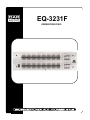
1
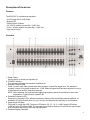
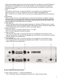
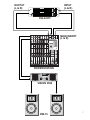
EQ-3231F
ORDERCODE D1923
Congratulations!
You have bought a great, innovative product from DAP Audio.
The DAP Audio EQ-3231F brings excitement to any venue. Whether you want simple plug-&-play action or
a sophisticated show, this product provides the effect you need.
You can rely on DAP Audio, for more excellent audio products.
We design and manufacture professional audio equipment for the entertainment industry.
New products are being launched regularly. We work hard to keep you, our customer, satisfied.
For more information: [email protected]
You can get some of the best quality, best priced products on the market from DAP Audio.
So next time, turn to DAP Audio for more great audio equipment.
Always get the best -- with DAP Audio !
Thank you!
DAP Audio
DAP Audio EQ-3231F Product Guide
Warning..…...................................................................................…………………………………………..
Safety-instructions………………………………………………………………………………………….….
Operating Determinations…………………………………………………………………………………….
2
2
3
Description..…..............................................................................……….…………………………………
Features………………………………………………………………………………….………………….….
Overview Front side..…………………………………………………………………………………....……
Overview Back side..…………………………………………………………………………………….……
4
4
4
5
Installation..................................................................……………………………..…………………………
6
Set Up and Operation.....................................................................……..…………………………….……
6
Connecting EQ-3231F………..………………………………………………………………………..….……. 7
Maintenance………..............................….......................................………..………….…….………….…..
8
Troubleshooting………..............................…................................………..………….…….………….…..
8
Product Specifications.................................................................……………….…….………………….
9
1
WARNING
CAUTION!
Keep this system away from rain and moisture!
FOR YOUR OWN SAFETY, PLEASE READ THIS USER MANUAL CAREFULLY
BEFORE YOUR INITIAL START-UP!
SAFETY INSTRUCTIONS
Every person involved with the installation, operation and maintenance of this system has to:
be qualified
follow the instructions of this manual
CAUTION! Be careful with your operations.
With a dangerous voltage you can suffer
a dangerous electric shock when touching the wires!
Before you initial start-up, please make sure that there is no damage caused by transportation. Should there
be any, consult your dealer and do not use the system.
To maintain perfect condition and to ensure a safe operation, it is absolutely necessary for the user to follow
the safety instructions and warning notes written in this manual.
Please consider that damages caused by manual modifications to the system are not subject to warranty.
This system contains no user-serviceable parts. Refer servicing to qualified technicians only.
IMPORTANT:
The manufacturer will not accept liability for any resulting damages caused by the non-observance of
this manual or any unauthorized modification to the system.
•
•
•
•
•
•
•
•
•
•
•
•
•
•
•
•
Never let the power-cord come into contact with other cables! Handle the power-cord and all
connections with the mains with particular caution!
Never remove warning or informative labels from the unit.
Never use anything to cover the ground contact.
Do not insert objects into air vents.
Do not connect this system to a dimmerpack.
Do not switch the system on and off in short intervals, as this would reduce the system’s life.
Do not open this device. Risk: hazardous radiation exposure.
Do not run the output of any amplifier channel, back into another channel’s input.
Do not connect (parallel or series) an amplifier output with any other amplifier output.
Only use system indoor, avoid contact with water or other liquids.
Avoid flames and do not put close to flammable liquids or gases.
Always disconnect power from the mains, when system is not used. Only handle the power-cord by
the plug. Never pull out the plug by tugging the power-cord.
Make sure you don’t use the wrong kind of cables or defective cables.
Make sure that the signals into the mixer are balanced, otherwise hum could be created.
Make sure you use DI boxes to balance unbalanced signals; All incoming signals should be clear.
Make sure that the available voltage is not higher than stated on the rear panel.
2
•
•
•
•
•
•
•
•
•
•
•
•
•
•
•
•
•
Make sure that the power-cord is never crimped or damaged. Check the system and the power-cord
from time to time.
Always operate the unit with the AC ground wire connected to the electrical system ground.
Connecting amplifier outputs to oscilloscopes or other test equipment, while the amplifier is in
bridged mode, may damage both the amplifier and test equipment.
Do not drive the inputs with a signal level bigger, than required to drive the equipment to full output.
In system setup, the amplifier's output power must be 50%-100% more than the loaded
loudspeakers rated power.
Please turn off the power switch, when changing the power cord or signal cable, or select the input
mode switch.
In typical use, Please set the volume to 0dB position.
Sometimes, when you want to send one signal to more than one amplifier, you should use a signal
distributor.
Extreme frequency boosts in connection with a high input signal level may lead to overdriving your
equipment. Should this occur, it is necessary to reduce the input signal level by using the INPUT
control.
To emphasize a frequency range, you don’t necessarily have to move its respective sliding control
upward; try lowering surrounding frequency ranges instead. This way, you avoid causing the next
piece of equipment in your sound path to overdrive. You also preserve valuable dynamic reserve
(“headroom”)
For replacement use fuses of same type and rating only.
Prevent distortion! Make sure that all components connected to the EQ-3231F have sufficient power
ratings. Otherwise distortion will be generated because the components are operated at their limits.
Avoid ground loops! Always be sure to connect the power amps and the mixing console to the same
electrical circuit to ensure the same phase!
If system is dropped or struck, disconnect mains power supply immediately. Have a qualified
engineer inspect for safety before operating.
If the system has been exposed to drastic temperature fluctuation (e.g. after transportation), do not
switch it on immediately. The arising condensation water might damage your system. Leave the
system switched off until it has reached room temperature.
Repairs, servicing and electric connection must be carried out by a qualified technician.
WARRANTY: Till one year after date of purchase.
OPERATING DETERMINATIONS
If this system is operated in any other way, than the one described in this manual, the product may suffer
damages and the warranty becomes void.
Any other operation may lead to dangers like short-circuit, burns, electric shock, etc.
You endanger your own safety and the safety of others!
Improper installation can cause serious damage to people and property !
3
Description of the device
Features
The EQ-3231F is a professional equalizer:
• 2x XLR Input and 2x XLR Output
• Bypass LED
• Output Signal VU Meter
• 40 - 400 Hz variable Hi-pass filter, 18 dB / Oct.
• 3 Khz – 20 Khz variable Low-pass filter, 18 dB / Oct.
• Input Level Control
Overview
1. Power Switch
Use this button to switch your equalizer on.
2. "POWER" Indicator
This indicator lights when the equalizer is switched on.
3. Increase / Reduce Fader
Of the 31 bands, each fader controls each band increase / reduce filter signal level. The maximum
increase / reduce of its central frequency is ± 15 dB. When the signal level has been adjusted, the curve
of the attenuator is the EQ’s frequency response.
NOTE: When adjusting, the level between neighboring frequency points, there should not be a wide
discrepancy, it usually doesn’t exceed 3 dB.
4. Feedback Frequency LED
There are 31 frequency LEDs. When any frequency display of the sound field produces feedback, its
feedback LED can accurately show it to you, and you can attenuate the frequency to non-feedback.
5. Output Signal VU Meter
This meter is a multi-step LED; The green LED shows –20, -15, -10, 0, +10dB, orange LED shows
+15dB and red LED shows +20dB. The accurate level indication allows you to monitor the output signal
level at anytime and match it with back-step equipment.
6. Feedback Display Threshold
4
When several feedback frequency levels are close to each other, and lead two or several LED bright at
the same time or the feedback level is low and the LED dark. You can use this button to adjust the
threshold level of feedback, so you can see clearly which frequency has feedback and take relevant
measures to restrain.
7. Filter
If you push the “Filter” button, it connects to the filter. You can adjust the cut-off frequency of the
high cut / low-pass (11) or low cut / high-pass (12) filter. The range is fully adjustable from
3Khz – 20 Khz (11) or 40 - 400Hz (12). You can use it as a variable subsonic filter and a low frequency
filter.
8. Bypass Button
When you press this button, all the adjustments you made with the faders are unavailable, except the
input gain control. It is convenient for the soundman to compare the signal before and after equalizing.
The circuit bypasses the signal directly from the input channel though relay to the output channel. The
indicator lights when the BY PASS function is available.
9. Output Clip LED
This LED indicates whether the output signal is clipped or not. When the LED flashes once in a while,
indicating the signal is sometimes clipped. When the LED frequently flashes, the signal is clipped often.
You should reduce the input, to the point the LED is not flashing anymore.
10. Input Level Control
This control allows you to adjust the input level from -∞ to +6dB.
NOTE: Too much adjustment can distort the signal.
11. High Cut Control
If you push the “Filter” button, it connects to the filter. You can adjust the cut-off frequency of the
high cut / low-pass filter. The range is fully adjustable from 3 KHz-20 KHz. You can use it as a variable
subsonic filter and a low frequency filter.
12. Low Cut Control
If you push the “Filter” button, it connects to the filter. You can adjust the cut-off frequency of the
low cut / high-pass filter. The range is fully adjustable from 40-400Hz. You can use it as a variable
subsonic filter and a low frequency filter.
EQ-3231F DESCRIPTION REAR PANEL:
13. Input / Output Connector - 1/4” Stereo Jack (Balanced)
The 1/4” stereo jack connector is balanced and wired as Tip=+, Sleeve=Ground, Ring= -.
5
The XLR input connector is balanced and wired as Pin 1=Ground, Pin 2=+, Pin 3= -.
NOTE: Only one of these sockets can be used for audio connection at the same time.
14. Remote Power Supply Input Socket
This is the remote AC power supply input socket for the EQ3231F. It is a special three cores socket.
The model for this power supply adapter is “YH-18A-1000”. In order to make your EQ-3231F work in a
stable and safe condition, please use this special power supply adapter we provide.
Installation
Remove all packing materials from the EQ-3231F. Check that all foam and plastic padding is removed.
Screw the equipment into a 19" rack. Connect all cables.
Always disconnect from electric mains power supply before cleaning or servicing.
Damages caused by non-observance are not subject to warranty.
Set Up and Operation
Before plugging the unit in, always make sure that the power supply matches the product specification
voltage. Do not attempt to operate a 120V specification product on 240V power, or vice versa.
Install this device on a flat surface, not bending or curved.
Do not supply power before all components of the system are set up and connected properly.
If you want to filtrate a frequency below 40 Hz, you have to use the “FILTER” button.
The feedback indicator of the EQ-3231F only hints a feedback frequency of the highest feedback level at the
same time. When more than two LEDs are illuminated as several feedback frequency levels are
approached, you can adjust “DISPLAY THRESHOLD” to select the biggest level in several frequencies.
Sometimes, the level of feedback frequency is lower than the indicated level (0dB). However if you want to
view the point, you can use “DISPLAY THRESHOLD” to lower the feedback threshold level until the LED of
the EQ is illuminated.
Don’t adjust two neighboring frequency points, which are far away from each other. Otherwise, it will result
in a frequency deflection.
For example: If 1 Khz is increased + 15 dB, and 1.6 Khz is reduced to –15 dB. In fact, a frequency of 800 Hz
– 1.25 Khz is increased 15 dB and a frequency of 1.6 Khz – 2.5 Khz is reduced 15 dB. This is a
phenomenon of an equalizer.
On the next page you will find an example how to connect the equalizer to your equipment.
6
OUTPUT
(L & R)
CH 1
FEEDBACK FREQUENCY DISPLAY
DISPLAY
THRESHOLD FILTER
VU
18dB/OCT
BY PASS
+20
+15
+15
+10
+10
+5
+15
+10
+5
0
0
-5
-5
-10
-10
-15
dB
-15
dB
25
31.5
40
50
63
80
100
125
160
200
250
315
400
500
630
800
1K
1.25K
1.6K
2K
2.5K
3.15K
4K
5K
6.3K
8K
10K
12.5K
16K
HIGH
OFF ON
0
60
-10
4K
LEVEL
0dB
-15
-20
dB
20K
40
400
Hz
3K
20K
Hz
8
20
CLIP
OUTPUT
LOW
INPUT
(L & R)
+6dB
CH 2
ON
DISPLAY
THRESHOLD FILTER
VU
18dB/OCT
BY PASS
+20
POWER
+15
+15
+10
+10
+5
+5
0
0
-5
-5
-10
-10
-15
dB
+15
+10
OFF ON
31.5
40
50
63
80
100
125
160
200
250
315
400
500
630
800
1K
1.25K
1.6K
2K
2.5K
3.15K
4K
5K
6.3K
8K
10K
12.5K
16K
60
-10
4K
-20
dB
20K
40
400
Hz
3K
20K
Hz
LEVEL
0dB
8
25
HIGH
-15
-15
dB
20
CLIP
OUTPUT
LOW
0
+6dB
EQ-3231F
LINE IN 5/6
LINE IN 7/8
LINE IN 9/10
MAIN INSERT
(L & R)
LINE IN 11/12
HALL-1
T=10.0S
EFFECT
ALT 3
ALT 4
MAIN MIX
POWERSTATION
HIGH POWER STEREO AMPLIFIER
Clip
Clip
STY
Signal
Channel 1
Signal
Protect
Protect
Active
Active
POWER
Channel 2
VISION 3500
7
RW-15
Maintenance
The EQ-3231F equalizer requires almost no maintenance. However, you should keep the unit clean.
Disconnect the mains power supply, and then wipe the cover with a damp cloth. Do not immerse in liquid.
Keep connections clean. Disconnect electric power, and then wipe the audio connections with a damp cloth.
Make sure connections are thoroughly dry before linking equipment or supplying electric power.
Troubleshooting
Dap Audio EQ-3231F
This troubleshooting guide is meant to help solve simple problems.
If a problem occurs, carry out the steps below in sequence until a solution is found. Once the unit operates
properly, do not carry out following steps.
1. If the device does not operate properly, unplug the device.
2. Check the power from the wall, all cables etc.
3. If all of the above appears to be O.K., plug the unit in again.
4. If you are unable to determine the cause of the problem, do not open the equalizer, as this may damage
the unit and the warranty will become void.
5. Return the equalizer to your Dap Audio dealer.
8
Product Specifications
Model: DAP Audio EQ-3231F
Power: AC2x 18V 500mA
S / N Rate: > 95dB
Frequency response: 20Hz – 20Khz (+/- 0.3dB)
THD %: <0.01%
Central frequency filter: 2 step filter
Precision of the central frequency: < +/- 1.5%)
Filter of input: Variable filter
The max increase / reduce of the frequency: +/- 15dB
Dynamic range: 118dB
Input gain: -∞ ~+6dB
Indicator: Power, Output VU, Low Cut Filter, Clip Output, By Pass, Feedback
Input impedance: Balanced 20KΩ / Unbalanced 10KΩ
Output impedance: Balanced 200Ω / Unbalanced 100Ω
Input connector: XLR (1=G, 2=+, 3=-), TRS (Tip +)
Output connector: XLR (1=G, 2=+, 3=-), TRS (Tip +)
Dimensions : 483 x 173 x 133 mm (LxWxH)
Weight : 3 kg
Design and product specifications are subject to change without prior notice.
9
2004 Dap Audio.