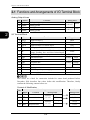
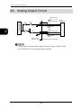
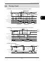
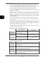
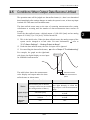
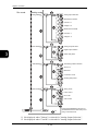
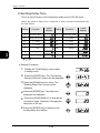
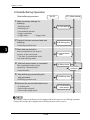
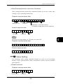
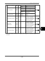
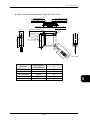
1
Compact Laser Displacement Sensor HL-G1 Series User's Manual WUME-HLG1-6 2013.12 panasonic.net/id/pidsx/global Introduction Thank you for purchasing the HL-G1-series Compact Laser Displacement Sensor. Read this manual carefully and be sure you understand the information provided before attempting to install and operate the product so that the product will fully demonstrate its superior performance. Refer to the website of Panasonic Industrial Devices SUNX Co., Ltd. (http://panasonic.net/id/pidsx/global) for the latest information on the product as well as the latest version of the manual. Note 1. The illustrations of the product in the manual may differ from the actual design of the product. 2. The contents of this user's manual may change without notice for possible improvements in the future. 3. All rights reserved. No part of this publication may be reproduced, stored in a retrieval system, or transmitted, in any form, or by any means, mechanical, electronic, photocopying, recording, or otherwise, without the prior written permission of Panasonic Industrial Devices SUNX Co., Ltd. 4. The utmost attention has been paid to the creation of this manual. Should you find any errors, omissions or inaccuracies, contact the nearest office of Panasonic Industrial Devices SUNX Co., Ltd. 5. Panasonic Industrial Devices SUNX Co., Ltd. shall be in no case responsible for any consequences resulting from your operation of the product. Conventions The following conventions are used to indicate and classify precautions in this manual. Always heed the information provided with them. Indicates information that, if not heeded, is likely to result in loss of life or serious injury. Indicates information that, if not heeded, could result in relatively serious or minor injury, damage to the product, or faulty operation. Explains matters that should be observed or mistakes that the user is apt to make. Explains items that should be kept in mind, relevant information in detail, and references. Explains useful operating conditions and technical tips (know-how). Introduction About this Manual Introduction Introduction provides precautions on the safe and correct use of this system. Be sure to read the precautions provided in this section. Chapter 1 provides information on the configuration, installation, and connection of the system (including the sensor head and Setting and monitoring software HL-G1SMI. 1 Chapter Chapter 2 provides information on the I/O lines of 2 I/O Terminal Block the sensor head. 2 Chapter 3 Functions Chapter 3 provides information on the functions of the system. 3 Chapter 4 Communications Chapter 4 provides information on RS-422 and RS-485 communications control. 4 Chapter Control 5 Troubleshooting Chapter 5 provides information on the troubleshooting of the system. 5 Chapter 6 Specifications Chapter 6 provides the specifications of the sensor head. 6 Chapter 1 Before Use 7章 第 仕様 センサヘッドの仕様を記載しています。 1 Introduction Table of Contents About this Manual······························· 1 Table of Contents ······························· 2 1-2 Part Names and Functions ···········1-6 1-3 Installation Method······················1-7 Safety Precautions·····························4 Extension Cable ··································· 1-7 Mounting Direction of Sensor Head ·········· 1-8 WARNING ········································ 4 Caution ············································ 4 Correct Handling ·······························5 1-4 Measurement of transparent objects ·················································1-12 Installation Environment······················· 5 Operating Environment························ 5 2 I/O Terminal Block ··················2-1 Ambient Temperature, Humidity, and Illuminance············································5 Power Supply Voltage·······························6 Environment ···········································6 2-1 Functions and Arrangements of I/O Terminal Block ·············································2-2 2-2 I/O Circuit··································2-4 Protective Structure ···························· 6 Warm-up Time ··································· 7 Countermeasures against Noise············ 7 Power Supply ···································· 8 NPN Type ··········································· 2-4 PNP Type············································ 2-5 2-3 Analog Output Circuit ··················2-6 2-4 Timing Chart······························2-7 2-5 Conditions When Output Data Become Unfixed ···················································2-9 Applicable Power Supply ···························8 Power Supply Sequence for Sensor Head ····8 Instantaneous Power Failure················· 8 Applicable Standards / Regulations ········ 9 CE Compliant Conditions ··························9 Contact for CE ·····································9 3 Functions ·····························3-1 Laser Product Handling ····················10 3-1 Classification of Functions············3-2 3-2 Function List & Initial Values ·········3-2 3-3 Operation of Each Function ··········3-5 JIS/IEC/GB ····································· 10 Laser Diode Sensor ······························· 10 Precautions ·········································· 10 Warning label········································ 10 3-3-1 Basic Operation························ 3-5 Panel Configuration······························· 3-5 Basic Operation···································· 3-6 Screen Transition in Setting Mode ············ 3-9 FDA ···············································11 Export to US ········································· 11 FDA Standards ······································ 12 3-3-2 Memory Change ······················3-11 3-3-3 Sensing Setting ······················ 3-13 Maintenance and Inspection ··············14 Maintenance Instructions························· 14 Inspection ············································ 14 Sampling Cycle ·································· 3-13 Shutter Time ······································ 3-14 Light Intensity Monitor·························· 3-15 3-3-4 Data Processing Settings·········· 3-16 1 Before Use ···························1-1 Average Times ··································· 3-16 Analysis Mode···································· 3-17 Span ················································ 3-19 Offset ··············································· 3-20 Zero-set OFF ····································· 3-21 1-1 System Configuration··················1-2 1-1-1 System Configuration ················ 1-2 1-1-2 List of System Components & Accessories ··································· 1-3 3-3-5 Output Settings ······················ 3-22 Sensor Head Accessories······················· 1-3 Extension Cable for Sensor Head (Optional for High-function Type Only) ····· 1-4 Setting and Monitoring Software HL-G1SMI (Optional for High-function Type Only) ········································· 1-4 Compact Console (Optional for High-function Type Only)··········································· 1-5 Judgment Output Selection··················· 3-22 Displacement Judgment······················· 3-24 Judgment Output OFF Delay ················ 3-25 Measurement Value Display on Panel ····· 3-27 3-3-6 Analog Settings ······················ 3-28 Analog Output Selection······················· 3-28 Analog Scaling ··································· 3-29 2 Introduction 3-3-7 Alarm Settings························ 3-31 Output Settings ·································· 4-19 Analog Settings ·································· 4-20 Alarm Settings···································· 4-20 System Settings ································· 4-21 Read Commands ······························· 4-22 Buffering Commands··························· 4-22 Analog Output at Alarm ························ 3-31 Digital Output at Alarm ························· 3-32 Alarm Delay Times ······························ 3-33 3-3-8 COM Settings························· 3-34 Terminating Resistor Selection ·············· 3-34 Sensor No. ········································ 3-35 Baud Rate········································· 3-36 Connection Mode ······························· 3-37 Sending Delay Time ···························· 3-38 4-4 Setting Address List ··················4-24 ■ Command Formats(MEWTOCOL)········ 4-25 ■ Error Response ································ 4-25 ■ Sensing Settings ······························ 4-26 Data Processing Settings ····················· 4-26 Output Settings ·································· 4-27 Analog Settings ·································· 4-27 Alarm Settings···································· 4-28 System Settings ································· 4-28 ■ Data Readout ·································· 4-28 ■ Buffering settings······························ 4-29 ■ Setting for Programmable Display (GT Series) ············································ 4-30 3-3-9 System Settings······················ 3-39 Timing Mode······································ 3-39 Laser Control ····································· 3-40 Eco Mode ········································· 3-41 View Version······································ 3-42 3-3-10 Other System Settings ············ 3-43 Initialize ············································ 3-43 Save ················································ 3-44 3-3-11 Measurement Control with External Input ······························· 3-45 Timing ·············································· 3-45 Zero Set ··········································· 3-45 Reset ··············································· 3-46 5 Troubleshooting·····················5-1 5-1 Corrective Actions······················ 5-2 5-2 Initialization ······························ 5-6 3-3-12 Buffering Settings (High-function type only)····································· 3-47 Data Buffering Operation······················ 3-48 Buffering Mode··································· 3-49 Buffering Rate ···································· 3-50 Accumulated Amount··························· 3-50 Trigger Points ···································· 3-51 Trigger Delay ····································· 3-51 Trigger Conditions······························· 3-52 Buffering Operation ····························· 3-53 Status Readout ·································· 3-53 Last Data Point ·································· 3-53 Binary Readout of Buffering Data ··········· 3-54 6 Specifications························6-1 6-1 Sensor Head Specifications ········· 6-2 6-2 Dimensions ······························ 6-7 Sensor Head ······································· 6-7 6-3 Characteristics ·························6-12 Beam Diameter ·································· 6-12 Mutual Interference Area ······················ 6-14 Output Characteristics ························· 6-17 Revision history ···································· 6-19 4 Communications Control ·········4-1 4-1 Communications Specifications ·····4-2 Specifications······································· 4-2 Pin Arrangement··································· 4-2 Connecting Example with External Device · 4-3 Communications Protocol······················· 4-5 Communications Condition Changes ········ 4-5 4-2 Type and Format of Commands ····4-6 4-2-1 Commands ······························ 4-6 Data Transmission/Reception·················· 4-6 4-2-2 Command Formats···················· 4-8 Error Response ·································· 4-15 BCC················································· 4-17 4-3 Command List ························· 4-18 Basic Settings ···································· 4-18 Data Processing Settings ····················· 4-18 3 Introduction Safety Precautions This product is used to detect objects, and does not incorporate control functions for the purpose of maintaining safety including the prevention of accidents. Do not use this product as a human sensor to protect human bodies. Use products that conform to the laws, regulations, and international standards, such as OSHA, ANSI, and IEC standards, for applications protecting human bodies. In order to ensure the correct use of the product, read this user manual carefully before use. WARNING ● Incorporate safety measures, such as a double safety mechanism, into the system if the use of the system is likely to result in injury or serious consequential loss. ● Do not use the system in combustion gas atmospheres. Otherwise, the system may result in explosion. ● This product was developed and manufactured for use in industrial environments. Caution ● Always observe the specifications including the ratings and ambient conditions. Otherwise, the system may result in overheating or generate smoke. ● Do not disassemble or modify the system. Otherwise, an electric shock may be received or the system may generate smoke. ● Do not touch the wires when the system is energized. Otherwise, an electric shock may be received. 4 Introduction Correct Handling Pay attention to the following items when installing and using the system. Installation Environment Do not install the system in the following places. • Places where the ambient temperature, humidity, or the illumination level of the light receiving surface is in excess of the operating environmental conditions. ( Refer to “Operating Environment”.) • Places that causes dew condensation as a result of radical temperature changes. • Places with corrosive gas or flammable gas. • Places with excessive dust, iron powder, or salt. • Places where organic solvents, such as benzine, paint thinner, and alcohol, and strong alkaline substances, such as ammonia and sodium hydroxide are likely to adhere to the system. • Places with strong vibration and shock. • Places exposed to direct sunlight. • Places where water, oil, or chemicals are sprayed. • Places where a heavy load is imposed on the sensor head. Operating Environment Ambient Temperature, Humidity, and Illuminance Ambient temperature • Use the system within the range of the specifications ( refer to Chapter 6 “Specifications”). Sensor head: -10°C to 45°C • Keep the following storage temperature range in the case of storing the sensor head. Sensor head: -20°C to 60°C • The life of the semiconductor laser depends on the operating ambient temperature. Take appropriate measures, such as the use of a cooling fan, to drop the ambient temperature of the sensor head as much as possible if the sensor head is used close to heat radiating objects. • The sensor head radiates heat as well. Therefore, be sure to install the sensor head in places with as good thermal conductivity as possible. Mount the sensor head to an aluminum or steel plate with a minimum surface area of 200 cm2 if the 5 Introduction ambient temperature is 40°C or higher. In the case of installing two or more sensor heads in parallel, mount each sensor head to an aluminum or steel plate with a minimum surface area of 200 cm2 and make sure that the ambient temperature does not exceed 40°C. Ambient humidity • Use the system within a relative humidity (RH) range of 35% to 85%. Do not use the system in places that may cause dew condensation as a result of radical temperature changes. Ambient illuminance of light receiving surface Make sure that the illumination level of the light receiving surface does not exceed 3,000 lx under incandescent light. Power Supply Voltage Be sure to supply a rated voltage of 21.6 to 26.4 VDC. Environment • The internal circuit may be damaged if an external surge voltage (single-polarity, full-wave voltage) in excess of 500 V ± 1.2 x 50 μs is imposed. Insert a surge absorber between power input terminals if the external surge voltage is likely to exceed 500 V. • Always keep the emitter and receiver of the sensor head clean. Make sure that the emitter and receiver are free of substances that refract light, such as water, oil, or fingerprints, or surface water, or matters that block light, such as dust and dirt. Clean the emitter and receiver with a soft lint-free cloth or lens cleaning paper. • Check that the receiver will not receive direct ambient light the same as the laser light in wavelength, such as sunlight. Mount an appropriate object, such as a light shield plate, to the sensor head if high accuracy is especially required. • Do not use the system in places with flammable or corrosive gas or excessive dust, places where water is sprayed, places exposed to direct sunlight, or places with strong vibration or shock. Protective Structure • The sensor head is of penetration-resistant type, but the connector is not of dust-, water-, or corrosion-proof construction. Therefore, Do not use the product underwater or in the rain. Pay attention to the operating environment. 6 Introduction Warm-up Time In order to ensure the performance of the system, allow a warm-up time of at least 30 minutes after the system is turned ON. Countermeasures against Noise • Install the system separated as much as possible from noise generating sources, such as high-tension lines, high-voltage equipment, power lines, power equipment, machines generating high-voltage ON/OFF surges, welding machines, and inverter motors. • Install the system separated as much as possible from radio equipment incorporating transmission circuitry, such as amateur radio transmitters. ・ Do not touch the connector parts when the system is energized. Keep in mind that the internal circuit may be damaged if an excessive level of static electricity is imposed on the connector parts. • Separate the sensor cable from other wires at least 100 mm, and make sure that the sensor cable is not in parallel with them. Separate the sensor cable from high-voltage and power circuit lines. Shield the sensor cable with grounded conduits if it is unavoidable to lay the sensor cable together with high-voltage or power circuit lines. • Separate the I/O signal lines at least 100 mm away from power lines and power supply lines. All signal lines should be connected as short as possible. • The analog output of the system is adversely influenced by heavy noise in the power supply. In that case, use a noise filter or noise-cut transformer. • It is recommended to use shield cables for I/O signal wires and connect the shields to the frame ground (FG) for countermeasures against noise. • The analog output is easily affected by external noise. Use the shield cable and lay it as short as possible. • Ground the FG at a resistance not exceeding 100 independently. The FG may be adversely affected if the ground is shared with other equipment. 7 Introduction Power Supply Applicable Power Supply • Select a power supply with a maximum ripple of 0.5 V (peak to peak) and a minimum current capacity of 0.5 A. • Be sure to ground the FG terminal in order to prevent an adverse influence of high-frequency noise if a commercially available switching regulator is used for the power supply. • A transformer may be connected to the power supply on the condition that the transformer is of isolation type. The product or the power supply may be damaged if an auto transformer is used. • In order to protect the system from abnormally high voltages from the power supply line, be sure to use an isolated power supply with a built-in protective circuit. • In the case of using a power supply that does not incorporate a protective circuit, be sure to connect the power supply to the system through a protective element, such as a fuse. Power Supply Sequence for Sensor Head • Arrange a power supply sequence so that the sensor head will be turned ON earlier than the I/O power supply. • Arrange a power supply sequence so that the I/O power supply will be turned ON earlier than the sensor head. • Do not turn ON the sensor head again within 10 seconds after the sensor head is turned OFF. • The system will be ready to operate approximately 40 to 50 seconds after the system is turned ON, depending on the contents of settings. No outputs are determined during startup. Do not output anything during the period. • An analog voltage of 11 V and an analog current of approximately 21.6 mA will be output until the system becomes ready to operate. • Do not turn OFF the system while system settings are being saved. In the worst case, the sensor head system may be damaged and fail to restart. Instantaneous Power Failure If an instantaneous power failure occurs, the system will operate continuously or go to the initial power-on state, depending on the duration of the power failure. Do not use the system in environments where instantaneous power failures occur. 8 Introduction Applicable Standards / Regulations CE Compliant Conditions Make sure that the length of signal and power lines connected to the product is less than 30 m. Attach a ferrite core to the head cable as shown below. Recommended ferrite core: SEIWA ELECTRIC MFG. Co., Ltd.E04SR200935AB or equivalent one 30 mm max. 30mm以下 Contact for CE Panasonic Marketing Europe GmbH Panasonic Testing Center Winsbergring 15, 22525 Hamburg,Germany 9 Introduction Laser Product Handling JIS/IEC/GB Laser Diode Sensor The laser is classified in accordance with JIS (JIS C 6802: 2005), IEC (IEC 60825-1: 2007) and GB (GB 7247.1: 2012) standards. Model No. HL-G1□□-A-C5 HL-G1□□-S-J HL-G1□□A-RA-C5 HL-G1□□A-RS-J Wavelength 655 nm 655 nm Max. output 1 mW 0.39 mW Class 2 1 Precautions 1) Be careful not to stare at the laser beam directly or the reflected light of the mirror surface. 2) Install the sensor so the laser beam will be located higher or lower than eye level in order not to watch the beam directly while the system is in operation. 3) Contact the nearest office of Panasonic Industrial Devices SUNX Co., Ltd. if the system breaks down. The product is not provided with a function to stop laser beam radiation automatically when the sensor head is disassembled. Do not disassemble the sensor head, or otherwise you may be exposed to the laser beam. 4) Do not use the system in methods other than that specified in this manual. You may be exposed to hazardous laser radiation if the system is controlled or adjusted in procedures not specified in this manual. 5) Read the descriptions of the warning label carefully before use. The warning label (English) is affixed to the side of the sensor head. Warning labels in Japanese, Korean, and Chinese are enclosed. Use them as needed. 10 Introduction Warning label ● Diffuse reflection type In English In Japanese In Chinese In Korean <Label position> ● Specular reflection type <Label position> 11 Introduction FDA Export to US The laser product mounted on equipment and exported to the United States is subjected to the regulation of the Food and Drug Administration (FDA). In order to prevent the users’ injury caused by laser products, the FDA specifies PART 1040 (Performance Standards for Light-Emitting Products). The FDA classifies laser products according to the degree of risk and provides safety measures for respective classes. ( refer to “FDA Standards”.) ● Certification and Identification Label <Label position> 12 Introduction FDA Standards Class*1 Requirements I IIa II IIIa IIIb IV Performance (all laser products) Protective housing [1040.10(f)(1)] Safety interlock [1040.10 (f) (2)] Location of controls [1040.10(f)(7)] Viewing optics [1040.10(f)(8)] Scanning safeguard [1040.10(f)(9)] R*2 R*3,4 N/A R R R*2 R*3,4 R R R R*2 R*3,4 R R R R*2 R*3,4 R R R R*2 R*3,4 R R R R*2 R*3,4 R R R Performance (laser system) Remote interlock connector [1040.10(f)(3)] Key control [1040.10(f)(4)] Emission indicator [1040.10(f)(5)] Beam attenuator [1040.10(f)(6)] Manual reset mechanism [1040.10(f)(10)] N/A N/A N/A N/A N/A N/A N/A N/A N/A N/A N/A N/A R R N/A N/A N/A R R N/A R R R*10 R N/A R R R*10 R R*13 Performance (specific-purpose products) Medical [1040.11(a)] Surveying, leveling, alignment [1040.11(b)] Demonstration [1040.11(c)] S S S S S S S S S S*8 S S S*8 NP S*11 S*8 NP S*11 Labeling (all laser products) Certification/identification [1010.2,3] Protective housings [1040.10(g)(6),(7)] Aperture [1040.10(g)(4)] Class warning [1040.10(g)(1),(2),(3)] R D N/A N/A R R*5 N/A R*6 R R*5 R R*7 R R*5 R R*9 R R*5 R R*12 R R*5 R R*12 Information (all laser products) User information [1040.10(h)(1)] Product literature [1040.10(h)(2)(i)] Service information [1040.10(h)(2)(ii)] R N/A R R R R R R R R R R R R R R R R R: N/A: S: NP: D: Required Not applicable Requirements: Same as for other products of that Class. Not permitted Depends on level of inner radiation 13 Introduction *1 Class is based on the maximum level of laser exposure duringoperation. *2 Required wherever and whenever such human access to laser radiation levels that exceed the limits of Class I is not necessary for the product to perform its intended function. Required at the protective housing which is designed to be removed or displaced during operation or maintenance, if removal or displacement of the protective housing could permit human access to laser or collateral radiation. The requirements for interlock differ depending on the class of inner radiation. The contents of label differ depending on the level and wavelength of laser radiation inside the protective housing. Warning statement label *3 *4 *5 *6 *7 *8 *9 CAUTION logotype The method to measure the level of laser radiation to human body is required. CAUTION if 2.5mWcm-2 or less, DANGER if greater than 2.5mWcm-2. *10 *11 Time difference is needed between instruction and emission. Exception should be provided for demonstration of laser products or light shows using laser of Class IIIb or IV. *12 *13 DANGER logotype Required on and after August 20, 1986. 14 Introduction Maintenance and Inspection Maintenance Instructions • Be sure to turn OFF the system to stop laser emission before cleaning the system. • Molded resin is used in some parts of the system. Do not use organic solvents such as paint thinner or benzine to wipe the dirt on the system. • Do not wipe the glass portion of the laser aperture too strongly. Scratches on the glass may cause measurement errors. (1) Cleaning Emitter and Receiver on Front Side of Sensor Head • Always keep the emitter and receiver of the sensor head clean. Make sure that the emitter and receiver are free of substances that refract light, such as water, oil, or fingerprints, or surface water, or matters that block light, such as dust and dirt. Inspect the surfaces regularly and always keep them clean. • Blow away large particles of dust, if any, using a camera lens blower. • To remove small particles of dust or fingerprints, use soft lens cleaning cloth or lens cleaning paper and lightly wipe them out. • Use cloth moistened with a small amount of alcohol to wipe out tough dirt carefully. Inspection Inspect the system regularly to maintain the performance of the system and make it possible to use the system under optimum conditions. ● Major Inspection Items • Check that no I/O terminal connections are loose or disconnected. • Check that the glass surface on the laser aperture is free of dust, dirt or fingerprints. • Check that the power supply voltage is within the rated range (21.6 to 26.4 VDC). • Check that the operating ambient temperature during use is within the specification range (a sensor head temperature range of -10°C to 45°C). • Check that operating ambient humidity (RH) is within a range of 35% to 85%. 15 Introduction 16 1 1 Before Use This Chapter provides information on the configuration, installation, and connection of the system (including the sensor head and Setting and Monitoring Software HL-G1SMI). 1-1 System Configuration········· 1-2 1-1-1 System Configuration ·········· 1-2 1-1-2 List of System Components & Accessories ······················ 1-3 1-2 Part Names and Functions ···· 1-6 1-3 Installation Method ··········· 1-7 1-1 Chapter 1 Before Use 1-1 System Configuration 1-1-1 System Configuration The system configuration and equipment connecting cables are shown below. 1 Analog output Sensor head (Standard type) Each I/O Sensor head (High-function type) RS-422/485 Unilateral extension cable connector (2 m, 5 m, 10 m, and 20 m) RS-485 wiring can reach up to 16 units. Analog signal processing equipment (A/D board and digital panel) I /O control devices (PLC etc.) RS-422/485 communications control equipment RS-422/485 board USB-RS-422/485 converter Dedicated compact console and others System Configuration Example with Setting Tools (HL-G1SMI) Used PC Setting and Monitoring Software HL-G1SMI USB cable USB-RS-422/485 converter USB-RS-422/485 converter Recommended: SI-35USB (LINEEYE made) or GT02 series or GT12 series (Panasonic Industrial Devices SUNX made) The user may use a different converter at the user's own discretion. Dedicated software (to be downloaded from the website of Panasonic Industrial Devices SUNX) is required if the GT02 or GT12 series is used as a converter. 1-2 Chapter 1 Before Use 1-1-2 List of System Components & Accessories Sensor Head Accessories The accessories of the sensor head are shown below. Sensor head (Standard type) Sensor head (high-function type) 1 Sensor Head Instruction Manual Warning label ●Diffuse reflection Sticker: English Attachments: Japanese x 1 set Chinese x 1 set Korean x 1 set Japanese / English and Chinese / Korean ●Specular reflection 1-3 Chapter 1 Before Use Extension Cable for Sensor Head (Optional for High-function Type Only) 1 2m HL-G1CCJ2 5m HL-G1CCJ5 10 m HL-G1CCJ10 20 m HL-G1CCJ20 Setting and Monitoring Software HL-G1SMI (Optional for High-function Type Only) Software for the Setting and Monitoring Software HL-G1SMI can be downloaded from the website of Panasonic Industrial Devices SUNX Co., Ltd. (http://panasonic.net/id/pidsx/global). 1-4 Chapter 1 Before Use Compact Console (Optional for High-function Type Only) The GT-series Programmable Display of Panasonic Industrial Devices SUNX Co., Ltd. is available as a compact console for the HL-G1. Write dedicated screen data to the Programmable Display so that the Programmable Display will display HL-G1 settings and measurement values transmitted over RS-422 and RS-485 communication. Compact Console Compact console brackets and screws Terminal block for compact console GT-series product numbers applicable No. of connecti on units Product name Screen Backlight Body color Pure black GT02G GT02M Hairline AIG02GQ15D silver White/Pink/Red Pure AIG02MQ14D black Hairline AIG02MQ15D silver Pure black GT12G Green/Orange/Red 4.6-type STN 320 x 120 dots Multi connection (1 to 4 units) GT12M AIG02GQ14D Green/Orange/Red 3.8-type STN 240 x 96 dots Single connection Part no. Hairline AIG12GQ05D silver AIG12GQ15D Pure black White/Pink/Red AIG12GQ04D AIG12GQ14D AIG12MQ04D AIG12MQ14D Hairline AIG12MQ05D AIG12MQ15D silver The screen data and User’s Manual (Console-dedicated version) can be downloaded from the website of Panasonic Industrial Devices SUNX Co., Ltd. (http://panasonic.net/id/pidsx/global). 1-5 1 Chapter 1 Before Use 1-2 Part Names and Functions (1) Laser Indicator (LASER) Lights up in green during laser emission. (1) (2) (3) 1 (4) (5) (8) (6) (2) Alarm Indicator (ALARM) Lights up in orange if a measurement alarm results. (3) OUT1 Indicator (OUT1) Lights up in yellow during OUT1 output. (4) OUT2 Indicator (OUT2) Lights up in yellow during OUT2 output. (7) (5) OUT3 Indicator (OUT3) Lights up in yellow during OUT3 output. (9) (6) [ENTER] Key Used to enter items. (10) (7) Digital Display Displays measurement values and system errors. (11) (8) [UP] Key Used to select items. (9) [DOWN] Key Used to select items. (10) Emitter Emits the laser light. (11) Receiver Receives reflected light from measurement targets. 1-6 Chapter 1 Before Use 1-3 Installation Method Before installing each device, read carefully the explanation of the setting environment, concern about noise and radiation, and power supply. ( Refer to “Introduction” – “Correct Handling”.) Fix the sensor head securely with M4 screws inserted into the two screw holes of the sensor head. • The tightening torque should be 0.8N·m or less. • Never impose force around the connectors of the sensor head cable and extension cable. Do not bend the cables near the connectors. Doing so may result in cable disconnection. • Pay utmost attention not to bend the sensor cable in excess if the sensor needs to be moved. Extension Cable 20 mm min. • Do not pull the cable with a force of 29.4N or over when wiring the cable when the sensor head is fixed. The cable may be bent with a radius of 30 mm or over. However, do not bend the cable within 20 mm of the sensor head. 1-7 R 30 mm min. 1 Chapter 1 Before Use Mounting Direction of Sensor Head Mount the sensor head in the direction shown below toward the measuring target in order to ensure the precise and stable measurement operation of the sensor head. ● Installation direction toward the moving target 1 • Measurement of targets with extremely different adjacent colors or materials When measuring a moving target that has extremely different adjacent colors or materials, set the direction of the sensor head as shown below in order to minimize the measurement error of the sensor head. • Measurement of rotating targets When measuring a rotating target, set the direction of the sensor head as shown below in order to minimize the adverse influence of vertical oscillation or displacement. 1-8 Chapter 1 Before Use • Measurement of targets with level differences When measuring a moving target that has level differences, set the direction of the sensor head as shown below in order to minimize interference caused by the edges of the target. 1 ● Measurement of targets in narrow space or slots When measuring a target in a narrow space or slot, set the direction of the sensor head as shown below in order not to block the light path between the emitter and receiver. 1-9 Chapter 1 Before Use ● When mounting the sensor head to a wall surface Set the direction of the sensor head as shown below so that the receiver will not receive multi-reflected light from the wall. If the wall reflectance is high, painting the surface matte-black is effective. 1 1-10 Chapter 1 Before Use ● Sensor head angle to the center of measurement target for a diffuse reflection-type sensor Mount the sensor head so that the emitter and receiver will be located in parallel to each other as shown in the illustration on the right-hand side. Refer to “6-1 Sensor Head Specifications” for the measurement center distance and measurement range. 1 90° Model name HL-G103-A-C5 HL-G103-S-J HL-G105-A-C5 HL-G105-S-J HL-G108-A-C5 HL-G108-S-J HL-G112-A-C5 HL-G112-S-J HL-G125-A-C5 HL-G125-S-J Measurement center Measurement range distance 30 mm ±4 mm 50 mm ±10 mm 85 mm ±20 mm 120 mm ±60 mm 250 mm ±150 mm ● Sensor head angle to the center of measurement target for a specular reflection-type sensor Attach so that the receiver will receive light reflected directly as shown in the figure to the right. Installation angle Model name HL-G103A-RA-C5 HL-G103A-RS-J HL-G105A-RA-C5 HL-G105A-RS-J HL-G108A-RA-C5 HL-G108A-RS-J Measurement center distance Measuremen t range Installation angle 26.3 mm ±2 mm 15° 47.3 mm ±5 mm 10.39° 82.9 mm ±10 mm 7.53° 1-11 Chapter 1 Before Use 1-4 1 Measurement of transparent objects Because the measured value for the closest reflected wave will be output from the sensor when an HL-G1 series specular reflection-type unit measures a multi-reflecting reflector such as transparent glass, only surface measurement is possible. To accurately measure the surface of a transparent object, it is necessary to separate the reflected wave from the front surface and the reflected wave from the back surface. The following chart summarizes the thicknesses of glass that can be measured. Model name HL-G103A-R□ HL-G105A-R□ HL-G108A-R□ Measurable glass thickness (index of refraction of 1.55) 0.7 mm or more 2.0 mm or more 4.0 mm or more 1-12 2 I/O Terminal Block This chapter provides information on the I/O lines of the sensor head. 2-1 Functions and Arrangements of I/O Terminal Block ·························· 2-2 2-2 I/O Circuit··················· 2-4 2-3 Analog Output Circuit ········· 2-6 2-4 Timing Chart ················ 2-7 2-5 Conditions When Output Data Become Unfixed ························· 2-9 2-1 2 Chapter 2 I/O Terminal Block 2-1 Functions and Arrangements of I/O Terminal Block Analog Output Lines No. Name A(V) Analog voltage output 8 AGND Analog ground 9 A(I) Analog current output 10 AGND 2 Function 7 Wiring color Shield single Black conductor Shield single Gray conductor Analog ground I/O Terminal Block No. Name Function Wiring color 1 OUT1 Judgment output 1 Black 2 OUT2 Judgment output 2 White 3 OUT3 Judgment output 3 or alarm output Gray 4 TM Timing input Pink 5 MI Zero-set ON, Zero-set OFF, Reset, Memory change, Teaching, Save, and Laser Control inputs 6 NP NPN/PNP type switching input Violet Pink/Violet 11 +SD Transmission data Green Twistedpair wire Sky Blue 12 -SD Transmission data 13 +RD Reception data 14 -RD Reception data 15 SG Signal ground Shield 16 + V 24 VDC input for power supply Brown 17 0V Power supply ground Twistedpair wire Orange Yellow Blue Line colors on a label for connection included in sensor head produced before December 2010 describes line colors before this modification. Therefore, kindly confirm the following content before use. Content of Modification No. Before changes Name 11 +SD Transmission data 12 -SD Transmission data 13 +RD Reception data 14 -RD Reception data After Wiring color Function Twistedpair wire Twistedpair wire 2-2 Wiring color Black Green White Sky Blue Orange Orange White Yellow Chapter 2 I/O Terminal Block * MI input varies with the period of input as shown below. Period of input 30 ms 80 ms 130 ms 180 ms 230 ms 280 ms 330 ms 380 ms 430 ms 480 ms 530 ms 580 ms Function Zero-set ON Reset Memory change (M0) Memory change (M1) Memory change (M2) Memory change (M3) Teaching a (Determines displacement judgment value a) Teaching b (Determines displacement judgment value b) Zero-set OFF (Cancel) Save Laser ON Laser OFF MI input Input time T Enter MI input for the desired period with a tolerance of ±10 ms (T±10 ms). Two or more MI inputs can be entered in sequence on the condition that a minimum interval of 10 ms is set between adjacent MI inputs. • No SD/RD lines are prepared for HL-G1□□-A-C5 standard types. • The action of NP switching input is determined by the input state of the sensor head with the power turned ON. • The sensor head does not save setting changes made over the multi-input line. Save the settings over the multi-input line, through the panel, with the communications command, or with the operation of the console if the settings need to be maintained after the system is turned OFF. 2-3 2 Chapter 2 I/O Terminal Block 2-2 I/O Circuit NPN Type Lead wire color (Brown) + V (Black) Output 1: OUT1 Load 50 mA max. (White) Output 2: OUT2 Load 50 mA max. 2 External power supply 3 to 24 VDC Main circuit (Gray) Output 3: OUT3 Load 50 mA max. (Pink/Purple) NPN/PNP type switching input 3.3V 3.3V Main power supply 24 VDC ± 10% Ripple 0.5 V (peak-to-peak) included (Pink) Timing Input: TM (Purple) Multiple input: MI *1 (Blue) 0V Sensor head internal circuit External connection example *1 Non-voltage contact IN 0V 2-4 Chapter 2 I/O Terminal Block PNP Type Lead wire color (Brown) + V (Black) Output 1: OUT1 Load 50 mA max. (White) Output 2: OUT2 Load 50 mA max. 2 (Gray) Output 3: OUT3 Load 50 mA max. Main circuit (Pink/Purple) NPN/PNP type switching input Main power supply 24 VDC ± 10% Ripple 0.5 V (peak-to-peak) included *1 External power supply 5 to 30 VDC (Pink) Timing Input: TM (Purple) Multiple input: MI (Blue) 0V Sensor head internal circuit External connection example *1 Non-voltage contact or PNP transistor open collector output IN IN or 0V 0V High [5 V to 30 VDC (inrush current of 0.04 mA max.)]: Enabled Low [0 to 0.6 VDC or open]: Disabled 2-5 Chapter 2 I/O Terminal Block 2-3 Analog Output Circuit Lead wire color 0 to 11 V 2 Main circuit 100 (Shield) Analog ground: AGND AGND +V 3.2 to 22 mA 22 Analog (Black) Analog voltage output: input device A (V) AGND Sensor head internal circuit (Gray) Analog current output: A (I) (Shield) Analog ground: AGND External connection example • Do not short-circuit the analog output terminals or apply voltage to them. • Use shielded wires for the analog output terminals. 2-6 Chapter 2 I/O Terminal Block 2-4 Timing Chart ● NORMAL measurement (with timing mode set to “Hold”) Data is kept on hold by timing input. Sensor measurement Zero Zero set ON Zero set OFF Reset ON OFF Laser Laser OFF ON Sensor measurement and output Data unfixed status Data unfixed status with laser stopped Data unfixed status Data unfixed status Zero set ON Zero set OFF 2 Reset Multiple input * OFF ON (Zero set input operation) (Reset input operation) OFF ON (Laser input operation) Timing input * The function of multiple input varies with the period of input. Zero set ON: 30ms Zero set OFF: 430 ms Laser ON: 530 ms Laser OFF: 580 ms Reset: 80 ms ● NORMAL measurement (with timing mode set to “One-shot”) Sensor measurement Zero Sensor measurement and output A zero set in the data unfixed status is ignored. Data unfixed status Zero set ON Reset Zero set OFF Laser Zero set Laser OFF ON ON Multiple input ON OFF ON (Zero set input operation) Reset (Reset input operation) OFF ON (Laser input operation) Timing input For the period of multiple input time, refer to NORMAL measurement (with timing mode set to Hold) ● PEAK measurement Reset with timing input turned OFF Sensor measurement Zero Data unfixed status Data unfixed status Timing input Reset input (80 ms) 2-7 Sensor measurement and output Data unfixed status Chapter 2 I/O Terminal Block 2 • A zero set will be enabled by timing input while the HOLD status is valid. • A reset input by timing input during the HOLD status will cause a data unfixed status. The system will hold this status until the timing input is cancelled. • No zero set will be enabled while the data unfixed status is kept on hold. • The system will hold reset input while the data unfixed status is valid until the timing input is cancelled. • Judgment output is determined by the measured value and “displacement judgment”. The output will be turned OFF while the data unfixed status is valid. • When any data unfixed status other than that caused by reset input is valid, the console displayed value, analog output, and judgment output will become the same in performance. • Analog output during the data unfixed status is indicated by the initial setting. • If the system has been set to “Offset”, the offset value will be added when a zero set is executed. • If a zero set is executed during PEAK to PEAK measurement, the present measurement value will become zero (i.e., the reference value of measurement). Therefore, the measurement value will start from a negative (-) value if the system is reset while a zero set is executed. • If “digital output at alarm” is fixed, the judgment output of the sensor head will be interlocked with the fixed value. Processing of zero set/timing/reset inputs Reset input (during data unfixed time) On timing input Reflected at the time of zero set Zero set input input (on console displayed value (ON/OFF) and analog output). The data unfixed status is kept on hold. Timing input Reset input Invalid A data unfixed status will occur at the time of reset input (HOLD status while timing input is ON). Function of timing input (level) Analysis mode Function The measurement value will be kept on hold with timing input turned NORMAL ON in this mode, and the hold status will be canceled with the timing measurement input turned OFF. PEAK measurement VALLEY measurement The measurement value will be kept on hold at the moment the input signal turned ON in this mode, and the hold status will be canceled with the input signal turned OFF. The peak (bottom) value will be reset when the HOLD status is cancelled. The measurement value will be kept on hold at the moment the input PEAK to PEAK signal is turned ON in this mode, and the hold status will be canceled measurement with the input signal turned OFF. The data will be set to zero when the HOLD status is cancelled. 2-8 Chapter 2 I/O Terminal Block 2-5 Conditions When Output Data Become Unfixed The operation status will be judged as a data unfixed status (i.e., there is no determined data) immediately after settings changes are made, the system is reset, or laser stop input is turned ON. This status is not an alarm status. The data unfixed status starts at the time of restarting measurement after setting refreshment or resetting until the number of data measurement times reaches an average. Under the data unfixed status, a digital output of -999.9999 [mm] and an analog output of 11.000 [V] or 21.6 [mA]*1 will be turned ON. *1 This is the initial value. Under the data unfixed status, the analog output of the refer to system can be changed to a fixed value. For more information, “3-3-7 Alarm Settings” – “Analog Output at Alarm”. *2 Under the data unfixed status, the zero set input will be ignored. refer to Chapter 5 “Troubleshooting”. *3 For cancelling the data unfixed status, For example, the graph on the right-hand side shows the digital display at reset input for NORMAL measurement. The table below shows the measurement value display and output under the data unfixed status or alarm status. Data unfixed status Status Reset input Data unfixed status (Data remeasurement period) Alarm status Measurement disabled status due to Measurement data is unfixed. poor light intensity or when the (Average buffer has not reached target object is off the measurement the setting number of times.) range. The previous value (default) is kept on hold. Interlocks with the analog output The previous value (default) is kept Analog output at alarm on hold. Terminal OFF OFF output Digital output -999.9999 [mm] 2-9 2 Chapter 2 I/O Terminal Block The following conditions will result in the data unfixed status. • Reset input after the power is turned ON • Sampling cycle switching • Initialization • Laser control interruption • Average times switching 2 * There are cases where the data unfixed status does not occur depending on the setting conditions. 2-10 3 Functions This Chapter provides information on the functions of the system. 3-1 Classification of Functions·································· 3-2 3-2 Function List & Initial Values ····························· 3-2 3-3 Operation of Each Function······························· 3-5 3-3-1 Basic Operation·························································3-5 3-3-2 Memory Change ···················································· 3-11 3-3-3 Sensing Setting ······················································ 3-13 3-3-4 Data Processing Settings·································· 3-16 3-3-5 Output Settings······················································· 3-22 3-3-6 Analog Settings ······················································ 3-28 3-3-7 Alarm Settings ························································· 3-31 3-3-8 COM Settings ·························································· 3-34 3-3-9 System Settings ····················································· 3-39 3-3-10 Other System Settings······································ 3-43 3-3-11 Measurement Control with External Input························································································ 3-45 3-3-12 Buffering Settings (High-function type only) ························································································ 3-47 3-1 3 Chapter 3 Function 3-1 Classification of Functions In this system, all functions are classified into eight categories to ensure stable measurement and various outputs. Classification Function Sensing Settings Function settings for precise and stable measurement by controlling the received light intensity of the sensor. Data Processing Settings Function settings for processing measurement values. Output Settings Function settings related to output data processing. Analog Settings Function settings related to analog output processing. Alarm Settings Function settings related to alarm output processing. COM Settings Function settings related to communication. System Settings System settings such as "Initialization," "Save," and communications settings. Buffering Settings * * Function settings related to buffering. This function is available to high-function type serial communication for which no panel settings are possible. 3-2 Function List & Initial Values Class Function Sensing settings Memory Change Data Processing Settings 3 Panel display Sampling Cycle Shutter Time Memory Ref. Initial value change* page Details Changes memory for saving the setting contents. 3-11 Default: M0 Sets the sampling cycle for measurement. Default: 500 µs Controls the receiving light intensity of the sensor according to the amount of reflected light from Default: Auto measurement targets. Light Intensity Monitor Checks the current received light intensity. Average Times Sets the average number of times of moving average. Analysis Mode Sets the analysis mode. Span Sets the measurement coefficient. Offset Sets the measurement offset. Zero-set OFF Clears the zero-set state. Default: 1024 3-2 3-13 3-14 - 3-15 3-16 3-17 Default: 1.0000 3-17 Default: 00000 mm 3-20 Default: OFF 3-19 Default: Normal measurement Chapter 3 Function Class Function Output Settings Judgment Output Selection Analog Output Selection Analog Settings Sets the operation of the output block. Meas A Current A Analog Scaling Voltage a Meas B Current B Turns OFF the rightmost digits on the digital display. Default: SET 1 Selects the desired output type from current output and voltage output. Alarm Settings Analog Output at Alarm Digital Output at Alarm Alarm Delay Times Terminating Resistor Selection 3-22 3-24 3-25 3-27 3-28 Default: Current output Performs scaling the analog current output and the analog voltage output to any desired value. Default: Negative measurement range Default: +4.000 mA Default: 0.000 V Default: Positive measurement range Default: +20.000 mA Default: 10.000 V Voltage b COM Settings Default: 2-state Default: +(detection range) Displace Threshold a Sets threshold a Default: -(detection range) ment Threshold b and threshold b. Judgment Default: +(0.2% of setting range) Hysteresis Sets the hysteresis. Judgment Output OFF Delays the timing of judgment output switched OFF Default: OFF from ON. Delay Measurement Value Display on Panel System Settings Memory Ref. Initial value change* page Details Sets the analog output status at alarm operation. Default: Holds previous value Sets the digital output status at alarm operation. Default: Holds previous value Holds the previous normal value up to the setting number of times if an alarm is issued. Default: 8 times 3-29 3-31 3-32 3-33 Selects the terminating resistor for the sensor head connecting to the host device over RS-422/485. 3-34 Default: R3 Sensor no. Sets the number of each sensor head multi connected Default: 01 to an RS-485 device. 3-35 Baud rate Sets the communication speed. Default: 38400 bps 3-36 Connection Mode Selects the performance settings for measurement data Default: RS-485 Multiple output to the host device. 3-37 Sending Delay Time Set the sensor's delay time in response to each command transmitted from the host device.Default: 0ms 3-38 Timing Mode Sets the timing input mode. Default: Hold 3-39 Laser Control Switches laser emission/stop. Default: Emission 3-40 Eco Mode Turns OFF the LED indicators on the control panel for energy saving while the system is in RUN mode. 3-41 Default: Eco OFF View Version Displays the program version of the sensor. - 3-42 Initialization Initializes the memory settings currently in use. 3-43 Save Saves all memory settings. 3-44 Timing Holds the measurement value. 3-45 3-3 Default: OFF 3 Chapter 3 Function Class Function Reset Resets the measurement value. Buffering Mode Sets the buffering mode. Default: Continuous mode 3-49 Buffering Rate Loads measurement data for a long duration by decimating the measurement data during data Default: 10 accumulation. 3-50 Buffering Settings Accumulated Amount Sets the amount of accumulated data. 3-50 Default: 3000 data items Trigger Point Sets the trigger generation position in the accumulated Default: 300 data. 3-51 Trigger Delay Delays the timing of accumulation after the trigger Default: 0 generation. 3-51 Sets the conditions of trigger generation. Trigger Conditions Starts buffering with buffering-related parameters set Default: Stop in advance. Checks the operation status of accumulation. Status Readout 3-52 Default: At timing input ON Buffering Operation 3 Memory Ref. Initial value change* page Default: OFF 3-46 Details Default: Non-buffering 3-53 - 3-53 Last Data Point Reads out the accumulation status from the amount of measurement data. - 3-53 Binary Readout of Buffering Data Reads out the accumulated data. - 3-54 * Memory change : Up to four types of settings can be saved by performing memory change. : Settings cannot be changed by performing memory change. : Settings are saved as common settings for all memories. Settings cannot be executed on a memory-to-memory basis. • COM settings and buffering settings are functions dedicated to the high-function type. These settings are not used for the standard type. • Buffering settings cannot be made through the control panel. Make settings with serial communications commands. • Each set value is saved in either one of the following ways depending on the operating method selected. <Control panel of sensor head> Press the [ENTER] key to save after a set value change is made. <Serial communications command (High-function type only)> Execute the “Save” command after making a setting change. The execution of the “Save” command is required after making a setting change in the case of using the Setting and Monitoring Software HL-G1SMI for the dedicated console (sold separately). 3-4 Chapter 3 Function 3-3 Operation of Each Function 3-3-1 Basic Operation Panel Configuration (3) (1) (2) (4) (1) [ENTER] Key Used to enter items. 3 (2) Digital Display Displays measurement values, set values, and system errors. (3) [UP] Key Used to select items. (4) [DOWN] Key Used to select items. Digital Display The decimal point position varies with each model. Measurement value and set value 30-mm type 50/80/120-mm type Data unfixed status Alarm status with the “digital output at alarm” set to a fixed value. 30-mm type 50/80/120-mm type 3-5 Chapter 3 Function Basic Operation The following section explains how to operate the system in RUN mode after the system is turned ON, make function changes in the system, and reset the system to RUN mode, along with the shortcut functions of the system in RUN mode. The operation of the system common to each function is explained below. For refer to more information on settings peculiar to the respective functions, "3-3-2 Memory Change" through "3-3-9 System Settings." Turn the power ON + Turn the power ON (7) Initialization (All LEDs lit) (1) RUN mode 3 Short cut + (3) Zero set 2s + (4) Reset (2)Setting mode 2s (5) Threshold a 2s (6) Threshold b 3-6 Chapter 3 Function (1) RUN mode The measurement value will appear on the digital display in this mode. The system will be set to this mode when the system is turned ON. RS-422/485 write and read commands will be received while the system is in this mode. (2) Setting mode Use this mode to make setting changes. RS-422/485 write commands cannot be received while the system is in this mode. An error command indicating that the system is in setting mode will be returned if a write command is received. Refer to the next page for the transition of the screen while the system is in setting mode. (3) Zero set The measurement value will be set to zero in this mode. (4) Reset The measured value kept on hold by the system in measurement mode will be reset. (5) Threshold a The screen will change to the threshold-a setting screen. (6) Threshold b The screen will change to the threshold-b setting screen. (7) Initialization Initialization deletes all settings and returns them to the factory default settings. Supplemental remarks Setting changes in the control panel of the sensor head will be saved in the internal memory. 3-7 3 Chapter 3 Function ● Making Setting Value Changes "Span," "Offset," "Displacement judgment," "Analog scaling," "Number of alarm delay times" setting values can be changed freely. + Change value Change digit + + Change sign Change digit All digits flash 3 3-8 Change digit Chapter 3 Function Screen Transition in Setting Mode Run mode Setting mode 2s Sampling cycle Sensing setting Shutter time Light intensity monitor Data processing settings Average times Analysis mode Span Offset Zero set OFF Judgment output selection Output setting Threshold a Threshold b Hysteresis Judgment Output OFF Delay Measurement Value Display on Panel 2s 3-9 Pressing the [ENTER] key at least 2 s will determine the set value at any level and go into RUN mode. 3 Chapter 3 Function Run mode Setting mode Analog settings Analog output selection Measurement value A Current a *1 Voltage a *2 Measurement value B Current b *1 Voltage b *2 Alarm settings Analog output at alarm Digital output at alarm 3 Alarm delay times COM settings Terminating resistor selection Sensor no. Baud rate Connection mode Sending delay times System settings Timing mode Laser control Eco mode View version 2s Pressing the [ENTER] key at least 2 s will determine the set value at any level and go into RUN mode. *1 Not displayed when "Voltage" is selected for "Analog Output Selection." *2 Not displayed when "Current" is selected for "Analog Output Selection." 3-10 Chapter 3 Function 3-3-2 Memory Change The memory to save setting contents can be changed with M0 through M3. Setting M0 Memory M0 M1 Memory M1 M2 Memory M2 M3 * Function Panel display Memory M3 indicates the default value. • Select the first number to be changed when the system goes into setting mode. • A memory change will not switch the current memory until the memory change is executed after the system restarts. • Data unstability may result when the memory change is executed. • If setting changes are made with a serial communications command, save the changes so that the changes will be reflected when the system is turned ON again. ● Setting Procedure 1 Display the "Memory Change" screen while the system is in setting mode. 2 Press the [ENTER] key. The memory will be displayed. 3 Press the [UP]/[DOWN] key to make memory changes. (Example: Changing the memory to “M3”.) 4 Press the [ENTER] key to determine the memory. ● Memory Saving Settings Each function that has been set can be saved in four ways in the memory area in the sensor head. Measurement and judgment conditions can be saved individually according to the type of measurement object. Therefore, memory number changes will be possible without entering the set values for a wide variety of functions. Memory changes are made with external commands and settings in the control panel. 3-11 3 Chapter 3 Function Storable Functions in Memory The function settings that can be stored in the memory are divided into two types. One of them can be stored in each specified memory number and the other one can be stored as setting values common to all memories. refer to "3-2 Function For the above two types of storable functions in detail, List & Initial Values". 3 3-12 Chapter 3 Function 3-3-3 Sensing Setting Sampling Cycle This function is used to make measurement cycle settings. When measuring an object with poor received light intensity, such as black rubber, extend the sampling cycle to get sufficient light to perform stable measurement. Frequency 200 μs 5 kHz 500 μs 2 kHz 1 ms 1 kHz 2 ms 500 Hz Panel display Meas. object Bright Brightness of meas. object Cycle Dark *1 The measurement range may become narrow depending on measurement object type. *2 indicates the default value. ● Setting Procedure 1 Display the "Sensing Setting" screen while the system is in setting mode. 2 Press the [ENTER] key. The "Sampling Cycle" screen will be displayed. 3 Press the [ENTER] key. The present sampling cycle will be displayed. 4 Press the [UP]/[DOWN] key to make sampling cycle changes. (Example: Changing the sampling cycle to 1 ms.) 5 Press the [ENTER] key to determine the sampling cycle. 3-13 3 Chapter 3 Function Shutter Time The shutter time controls the receiving light intensity of the sensor according to the amount of reflected light from measurement targets. If the shutter time is set to AUTO, the light intensity feedback function automatically controls the light intensity to an optimum level. In the case of fixing the shutter time, use the light intensity monitor and select a fixed value of approximately 1000 to 1300. Setting Function AUTO Shutter time automatic setting 1 to 31 Fixed (See the table below.) Initial value ● Setting Procedure 3 1 Display the "Sensing Setting" screen while the system is in setting mode. 2 Press the [ENTER] key. The "Sampling Cycle" screen will appear. 3 Press the [DOWN] key once. The "Shutter Time" screen will be displayed. 4 Press the [ENTER] key. The present shutter time will be displayed. 5 Press the [UP]/[DOWN] key to make shutter time changes. (Example: Changing the shutter time to 31.) 6 Press the [ENTER] key and determine the shutter time. The following table shows the relation between the set values for shutter time and actual shutter apertures. Set value AUTO 1 2 3 4 5 6 7 Shutter Shutter Shutter Shutter Set value Set value Set value aperture aperture aperture aperture Auto 8 0.24% 16 1.95% 24 15.9% 0.04% 9 0.31% 17 2.54% 25 20.7% 0.05% 10 0.40% 18 3.30% 26 26.9% 0.06% 11 0.53% 19 4.29% 27 35.0% 0.08% 12 0.68% 20 5.58% 28 45.5% 0.11% 13 0.89% 21 7.25% 29 59.2% 0.14% 14 1.16% 22 9.43% 30 76.9% 0.18% 15 1.50% 23 12.3% 31 100% 3-14 Chapter 3 Function Light Intensity Monitor This function is used to check the current received light intensity. The peak light intensity will be displayed in a range of 0 to 4095. ● Setting Procedure 1 Display the "Sensing Setting" screen while the system is in setting mode. 2 Press the [ENTER] key. The "Sampling Cycle" screen will appear. 3 Press the [DOWN] key twice. The "Meas Suf Selection" screen will be displayed. 4 Press the [ENTER] key. The present light intensity will be displayed. 3-15 3 Chapter 3 Function 3-3-4 Data Processing Settings Average Times This function is used to set the average number of times of moving average. Use the function to stabilize unstable measurement values (including variations). Setting 3 * Function 1 time 1-time moving average processing 4 times 4-time moving average processing 16 times 16-time moving average processing 64 times 64-time moving average processing 256 times 256-time moving average processing 1024 times 1024-time moving average processing Panel display indicates the default value. Data unstability may result until the movement average buffer reaches the setting number of times ( refer to "2-5 Conditions When Output Data Become Unfixed"). If there is an alarm when the moving average buffer is cleared, moving averaging will start after the alarm state is cleared. Moving averaging based on the previous data will be performed if an alarm occurs until the setting number of times is reached after moving averaging starts. ● Setting Procedure 1 Display the "Data Processing Setting" screen while the system is in setting mode. 2 Press the [ENTER] key. The "Average Times" screen will be displayed. 3 Press the [ENTER] key. The present number of average times will be displayed. 4 Press the [UP]/[DOWN] key to change the number of average times. (Example: Changing the number of average times to 256.) 5 Press the [ENTER] key and determine the number of average times. 3-16 Chapter 3 Function Analysis Mode This function is used to set the analysis mode. The following table shows the function of each analysis mode. Setting Function NORMAL PEAK Holds and outputs the maximum measurement value. VALLEY Holds and outputs the minimum measurement value. PEAK to PEAK (P-P) Holds and outputs the difference between the maximum and minimum values. * Panel display The measurement value is output in real time. indicates the default value. Peak to Peak can be used for vibration or eccentricity measurement. ● Setting Procedure 1 Display the "Data Processing Setting" screen while the system is in setting mode. 2 Press the [ENTER] key. The "Average Time" screen will be displayed. 3 Press the [DOWN] key once. The "Analysis Mode" screen will be displayed. 4 Press the [ENTER] key. The present analysis mode will be displayed. 3-17 3 Chapter 3 Function 5 Press the [UP]/[DOWN] key to make analysis mode changes. (Example: Switching to PEAK to PEAK mode.) 6 Press the [ENTER] key to determine the mode setting. 3 3-18 Chapter 3 Function Span The system can output measurement values with a span (factor) multiplied. Final measurement value = Span x measurement value + offset Output Final meas. value Meas. value Spanned meas. value Offset value 0 Center point of measurement Setting range 0.1000 to +9.9999 Function Set a span in a range from 0.1000 to +9.9999. ● Setting Procedure 1 Display the "Data Processing Setting" screen while the system is in setting mode. 2 Press the [ENTER] key. The "Average Time" screen will be displayed. 3 Press the [DOWN] key twice. The "Span" screen will be displayed. 4 Press the [ENTER] key. The present span will be displayed. The leftmost digit will be selected. 5 Press the [UP]/[DOWN] keys together to change the selected digit. 6 Press the [UP]/[DOWN] key to change the value of the selected digit. (Example: Changing the value to 2.0000.) 7 Press the [ENTER] key to determine the span. 3-19 Measurem ent range Initial value 3 Chapter 3 Function Offset A desired setting value can be added to/subtracted from the measurement value. Measurement judgment will be possible from an offset in combination with “displacement judgment” by setting the size of the master workpiece (reference measurement object) for the offset, measuring the master workpiece, and turning the “zero set” ON. Setting range -95000 to +95000 3 Function Initial value -Set an offset in a range from 95000 to +95000. (The decimal point position varies with each model.) • Set "Offset" and turn "Zero Set" ON to make the setting value an offset value. • The display limit of the measurement value is ±95000. Make sure that the setting value does not exceed the display limit. ● Setting Procedure 1 Display the "Data Processing Setting" screen while the system is in setting mode. 2 Press the [ENTER] key. The "Average Time" screen will be displayed. 3 Press the [DOWN] key three times. The "Offset" screen will be displayed. 4 Press the [ENTER] key. The present offset value will be displayed. The leftmost digit will be selected. 5 Press the [UP]/[DOWN] keys together to change the selected digit. 6 Press the [UP]/[DOWN] key to change the value of the selected digit or its sign. (Example: Changing the value to +2.500 [mm].) 7 Press the [ENTER] key and determine the offset value. 3-20 Chapter 3 Function Zero-set OFF This function cancels the zero set for measurement values. Setting Function Reset The zero set is not canceled. Hold The zero set is canceled. Panel display Supplemental remarks • External multi input (MI) can turn the zero set ON and OFF. ( Functions and Arrangements of I/O Terminal Block.") refer to "2-1 ● Setting Procedure 1 Display the "Data Processing Setting" screen while the system is in setting mode. 2 Press the [ENTER] key. The "Average Time" screen will be displayed. 3 Press the [DOWN] key four times. The "Zero-set OFF" screen will be displayed. 4 Press the [ENTER] key. "Yes/No" will be displayed. 5 Press the [UP]/[DOWN] key to make "Yes/No" changes. (Example: Maintaining the zero-set state.) 6 Press the [ENTER] key. 3-21 3 Chapter 3 Function 3-3-5 Output Settings Judgment Output Selection This function makes it possible to select the operation of the output block. An alarm will not be output if "3-state" is selected. The final decision process is done in digital measurements. When an alarm is turned ON, the value will be set to +999.9999 with which judgment processing will be performed, provided that a fixed value has been set with “digital output at alarm”. Output operation Display Threshold a Judgment Output Selection OUT1 OUT2 OUT3 Threshold b Displacement (+) 3 OUT1 Logic Judgment 1 Judgment 2 ON (OPEN) Output status Output status OFF Alarm OUT2 ON (OPEN) Output status OFF Independent Judgment 1 Judgment 2 OUT1 ON (OPEN) Output status OFF Alarm OUT2 ON (OPEN) Output status OFF 2-state Judgment 1 Judgment 2 OUT1 ON (OPEN) Output status Output status OFF Alarm OUT2 ON (OPEN) Output status OFF OUT1 (HI) 3-state Judgment 1 Judgment Judgment 2 3 OUT2 (GO) OUT3 (LO) * indicates the default value. 3-22 ON (OPEN) Output status OFF ON (OPEN) Output status OFF ON (OPEN) OFF Output status Chapter 3 Function OUT3 settings are related to the operation of the output lines. An alarm is output through the OUT3 output line unless a 3-state value has been set. The OUT3 indicator on the sensor head and the OUT3 output readout function, however, will be turned OFF without being interlocked with the alarm. Check the alarm state with the alarm indicator and alarm readout function. ● Setting Procedure 1 Display the "Output Setting" screen while the system is in setting mode. 2 Press the [ENTER] key. The "Judgment Output Selection" screen will be displayed. 3 Press the [ENTER] key. The present output type will be displayed. 4 Press the [UP]/[DOWN] key to make output type changes. (Example: Changing the output type to "Independent.") 5 Press the [ENTER] key to determine the output type. 3-23 3 Chapter 3 Function Displacement Judgment This function is used to set an upper limit (threshold a), lower limit (threshold b), and hysteresis for the judgment of measurement values. Item Panel display Setting range Threshold a -95000 to +95000 Threshold b -95000 to +95000 Hysteresis 0 to +95000 Function Sets threshold a, threshold b and hysteresis. Supplemental remarks The following default values apply. 3 Diffuse reflection Specular reflection Type Threshold a Threshold b Hystere sis Threshold a Threshold b Hystere sis 30 mm 50 mm 85 mm 120 mm 250 mm +4mm +10mm +20mm +60mm +150mm -4mm -10mm -20mm -60mm -150mm 8μm 20μm 40μm 120μm 300μm +2mm +5mm +10mm - -2mm -5mm -10mm - 8μm 20μm 40μm - • Make settings so that threshold a is larger than threshold b. The sensor head will perform automatic discrimination, however, if the opposite settings are made. • The decimal point position varies with each model. ● Setting Procedure(Setting Threshold a) 1 Display the "Output Setting" screen while the system is in setting mode. 2 Press the [ENTER] key. The "Judgment Output Selection" screen will be displayed. 3 Press the [DOWN] key once. The "Threshold a" screen will be displayed. 4 Press the [ENTER] key. The present threshold will be displayed. The leftmost digit will be selected. 5 Press the [UP]/[DOWN] keys together to change the selected digit. 6 Press the [UP]/[DOWN] key to change the selected digit or its sign. (Example: Changing the value to +5 [mm].) 7 Press the [ENTER] key to determine the threshold. 3-24 Chapter 3 Function Judgment Output OFF Delay This function delays the timing of switching ON to OFF of judgment output. 測 This function is useful for applying output to a control device when the output is changing at high speed. Setting Function OFF Output according to the sampling cycle. 2 ms 2-ms OFF-delay 4 ms 4-ms OFF-delay 10 ms 10-ms OFF-delay 20 ms 20-ms OFF-delay 40 ms 40-ms OFF-delay 100 ms 100-ms OFF-delay Hold * Panel display 3 Output once turned ON will be kept on hold. The output kept on hold will be released with reset input. indicates the default value. Judgment output timing ON (OPEN) OFF delay setting time OUT1 OFF ON (OPEN) OUT2 OFF ON (OPEN) OUT3 OFF The solid lines shows OFF setting actions. OFF timing will be delayed according to the OFF-delay set time as shown by the dotted lines. • If actual output is turned ON earlier than the OFF-delay set time, the OFF-delay set time will be enabled from the point where the output is turned OFF. • If "Logic" or "Independent" or "2-state" is selected with the judgment output selection function, OUT3 (alarm output) will not be OFF-delayed regardless of OFF-delay settings. 3-25 Chapter 3 Function ● Setting Procedure 1 Display the "Output Setting" screen while the system is in setting mode. 2 Press the [ENTER] key. The "Judgment Output Selection" screen will be displayed. 3 Press the [DOWN] key four times. The "OFF-delay" screen will be displayed. 4 Press the [ENTER] key. OFF-delay settings will be displayed. 5 Press the [UP]/[DOWN] key to make OFF-delay setting changes. (Example: Changing the setting to Hold.) 6 Press the [ENTER] key to determine the OFF-delay setting. 3 3-26 Chapter 3 Function Measurement Value Display on Panel The rightmost digits on the digital display can be turned OFF. Setting Function FULL All the digits are displayed. Set 1 The rightmost digit is OFF. Set 2 The rightmost two digits are OFF. Panel Display ● Setting Procedure 1 Display the "Output Setting" screen while the system is in setting mode. 2 Press the [ENTER] key. The "Judgment Output Selection" screen will be displayed. 3 Press the [DOWN] key five times. The "Measurement Value Display on Panel" screen will be displayed. 4 Press the [ENTER] key. The "Measurement Value Display on Panel" screen will be displayed. 5 Press the [UP]/[DOWN] key to make a setting change for the measurement value display on the panel. (Example: Changing the present setting to Set 2.) 6 Press the [ENTER] key to determine the setting for the measurement value display on the panel. ● Set2 usage example In this example "FULL" is changed to "Set2." 3-27 3 Chapter 3 Function 3-3-6 Analog Settings Analog Output Selection This function selects the desired output type from current output and voltage output. The accuracy of selected analog output will be guaranteed. Setting Function Current Output current Voltage Output voltage * indicates the default value. ● Setting Procedure 3 1 Display the "Analog Setting" screen while in setting mode. 2 Press the [ENTER] key. The "Analog Output Selection" screen will be displayed. 3 Press the [ENTER] key. The present output type will be displayed. 4 Press the [UP]/[DOWN] key to make output type changes. (Example: Changing the output type to voltage output.) 5 Press the [ENTER] key to determine the output type. 3-28 Panel display Chapter 3 Function Analog Scaling This function scales analog current output or analog voltage output to any desired value. Measurement values A and B on any two measurement point can be scaled with currents a and b or voltages a and b on any two points. Analog output is turned ON according to the scaling set for analog output selection. Analog output Current voltage [V]/Current [mA] b Voltage [V]/Current [mA] b’ a’ : Voltage/Current before change : Voltage/Current after change a Measurement range Measurement value A Item Panel display Measurement value B Setting range Function Initial value Meas A -95000 to +95000 Negative measurement range Meas B -95000 to +95000 Positive measurement range Current a +4.000 to 20.000 (*1) Current b (*1) Voltage a (*2) Voltage b (*2) +4.000 to 20.000 Make measurement value, current, and voltage settings. 0 to +10.000 0 to +10.000 *1 Not displayed when "Voltage" is selected for "Analog Output Selection." *2 Not displayed when "Current" is selected for "Analog Output Selection." Supplemental remarks The following default measurement values A and B apply. Type 30 mm 50 mm 85 mm 120 mm 250 mm Diffuse reflection Meas. Val A Meas. Val B -4 mm +4 mm -10 mm +10 mm -20 mm +20 mm -60 mm +60 mm -150 mm +150 mm 3-29 Specular reflection Meas. Val A Meas. Val B -2 mm +2 mm -5 mm +5 mm -10 mm +10 mm - 3 Chapter 3 Function • The display limit of the measurement value is ±95000. Make sure that the setting value does not exceed the display limit. • Check the input range of your input device such as AD board before setting. • The decimal point position of measurement values varies with each model. ● Setting Procedure Setting current a (current for measurement value A) 3 1 Display the "Analog Setting" screen while in setting mode. 2 Press the [ENTER] key. The "Analog Output Selection" screen will be displayed. 3 Press the [DOWN] key twice. The "Current a" screen will be displayed. 4 Press the [ENTER] key. The present set value will be displayed. The leftmost digit will be selected. 5 Press the [UP]/[DOWN] keys together to change the selected digit. 6 Press the [UP]/[DOWN] key to change the value of the selected digit. (Example: Changing the value to 5.000 [mA].) 7 Press the [ENTER] key to determine the set value. 3-30 Chapter 3 Function 3-3-7 Alarm Settings Analog Output at Alarm This function is used to set the analog output status at alarm operation. Analog output in the alarm state (where measurement is disabled owing to lack of light) can be kept on hold or set to a fixed value selectively. Setting Function Holds the analog output immediately before the alarm. Hold Fixed Value * Panel display Fixed-value output indicates the default value. Supplemental remarks • A fixed current output of 21.6 [mA] or voltage output of +11.000 [V] applies. • The fixed value is applied to the side set with "Analog Output Selection." • Check the input range of your input device such as AD board before setting. • The above settings will apply when there is data unstability. ● Setting Procedure 1 Display the "Alarm Setting" screen while in setting mode. 2 Press the [ENTER] key. The "Analog output at alarm" will be displayed. 3 Press the [ENTER] key. The Hold/Fix will be displayed. 4 Press the [UP]/[DOWN] key to set the system to Hold/Fix. (Example: Changing the selection to the fixed value.) 5 Press the [ENTER] key to determine the set value. 3-31 3 Chapter 3 Function Digital Output at Alarm This function is used to set the digital output status at alarm operation. This function makes settings related to digital output (on the digital display block of the sensor head and measurement values over serial communication) in the alarm state (where measurement is disabled owing to lack of light). The digital data will be set to +99999 if the fixed value is selected. The measurement value immediately before the alarm will be displayed if the system is set to hold. Selecting the fixed value can detect the alarm issued status easily from the measurement result. With this convenient function, the alarm status can be confirmed as well when the measurement value is loaded by data buffering function. Setting Function Hold 3 Fixed Value * Panel display Holds the digital output immediately before the alarm. Fixed-value output indicates the default value. • If the alarm state occurs after the fixed value is selected, judgment output interlocked with digital output will be turned ON. ● Setting Procedure 1 Display the "Alarm Setting" screen while in setting mode. 2 Press the [ENTER] key. The "Analog output at alarm" screen will be displayed. 3 Press the [DOWN] key once. The "Digital output at alarm" screen will be displayed. 4 Press the [ENTER] key. The present Hold/Fix will be displayed. 5 Press the [UP]/[DOWN] key to select Hold/Fix. (Example: Changing the selection to the fixed value.) 6 Press the [ENTER] key to determine the set value. 3-32 Chapter 3 Function Alarm Delay Times This function holds the previous normal value up to the setting number of times if an alarm is issued. The previous normal value will be kept on hold up to the setting number of delay times if an alarm is issued (where measurement is disabled owing to lack of light). Alarm output (OUT3) will be turned ON when the alarm status continues more than the setting number of delay times, and analog output and digital output will be turned ON according to the setting for analog output at alarm and the setting for digital output at alarm, respectively. This function is effective if the user does not require the output of instantaneous alarms resulting for the surface condition changes of measurement objects. Setting range 0 to 65534 65535 Function 0 (OFF) to 65534 times Holds the measurement value before the alarm. ● Setting Procedure 1 Display the "Alarm Setting" screen while in setting mode. 2 Press the [ENTER] key. The "Analog output at alarm" screen will be displayed. 3 Press the [DOWN] key twice. The "Alarm Delay Times" screen will be displayed. 4 Press the [ENTER] key. The number of alarm delay times will be displayed. The leftmost digit will be selected. 5 Press the [UP]/[DOWN] keys together to change the selected digit. 6 Press the [UP]/[DOWN] key to change the value of the selected digit. (Example: Changing the value to 0 times (OFF).) 7 Press the [ENTER] key and determine the number of delay times. 3-33 Initial value 3 Chapter 3 Function 3-3-8 COM Settings Make COM settings through the control panel. No COM settings are possible with serial communications commands. Terminating Resistor Selection This function selects the terminating resistor for the sensor head connecting to the host device over RS-422/485. Be sure to select R3 if the system is connected to RS-422 equipment. If a number of sensor heads are connected to RS-485 equipment, set R3 for the terminating sensor and the rest of the sensors to OFF. * The communication of the system, if unstable, may be improved by selecting R1 or R2. Setting OFF 3 * Function Turn OFF terminating resistors R1 Terminating resistor R1 R2 Terminating resistor R2 R3 Terminating resistor R3 indicates the default value. ● Setting Procedure 1 Display the "COM Setting" screen while the system is in setting mode. 2 Press the [ENTER] key. The "Terminating Resistor Selection" screen will be displayed. 3 Press the [ENTER] key. The present terminating resistor will be displayed. 4 Press the [UP]/[DOWN] key to change the terminating resistor. (Example: Changing the resistor to OFF.) 5 Press the [ENTER] key to determine the terminating resistor. 3-34 Panel display Chapter 3 Function Sensor No. This function is used to set the number of each sensor head multi connected to an RS-485 device. Be sure to set each connecting sensor head number with no duplication. Setting range Function 01 to 16 Set sensor numbers 01 through 16 in sequence. Initial value ● Setting Procedure 1 Display the "COM Setting" screen while in setting mode. 2 Press the [ENTER] key. The "Terminating Resistor Selection" screen will be displayed. 3 Press the [DOWN] key once. The "Sensor No." screen will be displayed. 4 Press the [ENTER] key. The present sensor number will be displayed. 5 Press the [UP]/[DOWN] key to change the sensor number. (Example: Changing the sensor number to 16.) Supplemental remarks Press the [UP]/[DOWN] keys together for at least 2 seconds to move the set value at high speed. 6 Press the [ENTER] key to determine the sensor number. 3-35 3 Chapter 3 Function Baud Rate This function is used to set the communication speed. Setting 9,600 bps 19200 19,200 bps 38400 38,400 bps 115200 115,200 bps 230400 230,400 bps 460800 460,800 bps 921600 * 3 Function 9600 Panel display 921,600 bps indicates the default value. • Lower the communication speed if stable communication with the host device is not possible. ● Setting Procedure 1 Display the "COM Setting" screen while in setting mode. 2 Press the [ENTER] key. The "Terminating Resistor Selection" screen will be displayed. 3 Press the [DOWN] key twice. The "Baud Rate" screen will be displayed. 4 Press the [ENTER] key. The communication speed will be displayed. 5 Press the [UP]/[DOWN] key to make communication changes. (Example: Changing the communication speed to 115,200 bps.) 6 Press the [ENTER] key to determine the communication speed. 3-36 Chapter 3 Function Connection Mode This function is used to select the performance settings for measurement data output to the host device. Select the operation settings for measurement data output to the host device. This section provides information on the condition that the RS-422 device is connected 1-to-1 and the RS-485 device is connected 1-to-N (sensor heads) to the refer to "4-1 Communications system. For the connection method, Specifications - Connecting Example with External Device." For details of the dedicated output format, refer to "4-2 Type and Format of Commands". Connection method Setting Function Transmits the result data (a response command) in response to a request command from the host device. All commands can be received. RS-422 handshake RS-422 Timing RS-422 Transmits the measured value in the exclusive output format when timing input is ON while the system is in this mode. RS-422 Continuous Transmits the measured value continuously in the exclusive output format after this mode is selected. RS-485 Multiple Up to 16 sensor heads are connected to the host device. Transmits the result data (a response command) in response to a request command from the host device. No sensors outside the designated range will not respond. * Panel display RS-485 indicates the default value. ● Setting Procedure 1 Display the "COM Setting" screen while in setting mode. 2 Press the [ENTER] key. The "Terminating Resistor Selection" screen will be displayed. 3 Press the [DOWN] key three times. The "Connection Mode" screen will be displayed. 4 Press the [ENTER] key. The present connection mode will be displayed. 5 Press the [UP]/[DOWN] key to change the connection mode. (Example: Changing the connection to RS-485 multi connection.) 6 Press the [ENTER] key to determine the connection mode setting. 3-37 3 Chapter 3 Function Sending Delay Time This is a useful function if the connection mode is set to RS-485 multi. Select the sensor's delay time in response to each command transmitted from the host device. Panel display Setting Function 0 No delay time 10 Delay time 10ms 0.1 Delay time 0.1ms 20 〃 20ms 0.2 〃 0.2ms 50 〃 50ms 0.5 〃 0.5ms 100 〃 100ms 1 〃 1ms 200 〃 200ms 2 〃 2ms 500 〃 500ms 5 〃 5ms 1000 〃 1000ms 3 * Setting Function indicates the default value. ● Setting Procedure 1 Display the "COM Setting" screen while in setting mode. 2 Press the [ENTER] key. The "Terminating Resistor Selection" screen will be displayed. 3 Press the [DOWN] key four times. The "Sending Delay Time" screen will be displayed. 4 Press the [ENTER] key. The delay time setting will be displayed. 5 Press the [UP]/[DOWN] key to change the connection mode. (Example: Changing the delay time to 20 ms.) 6 Press the [ENTER] key to determine the sending delay time setting. 3-38 Panel display Chapter 3 Function 3-3-9 System Settings Timing Mode This function is used to set the timing input mode. Set the operation of the system with timing input turned ON. For the operation of the system in this mode, refer to "2-4 Timing Chart." Setting Hold One Shot * Function Panel display Measurement hold with timing input Measurement variable with timing input indicates the default value. ● Setting Procedure 1 Display the "System Setting" screen while in setting mode. 2 Press the [ENTER] key. The "Timing Mode" screen will be displayed. 3 Press the [ENTER] key. Hold/One Shot will be displayed. 4 Press the [UP]/[DOWN] key to select Hold or One Shot. (Example: Changing the selection to "One Shot.") 5 Press the [ENTER] key to determine the set value. 3-39 3 Chapter 3 Function Laser Control This function is used to select the laser emission/stop. This function makes it possible to stop unrequired laser emission while the system is not in measurement operation. Setting Function Emission Laser emission is ON Stop Laser emission is OFF * Panel display indicates the default value. The system will be in a data unfixed state temporarily if the laser control is set to "Stop" and then set to "Emission." 3 ● Setting Procedure 1 Display the "System Setting" screen while the system is in setting mode. 2 Press the [ENTER] key. The "Timing Mode" screen will be displayed. 3 Press the [DOWN] key once. The "Laser Control" screen will be displayed. 4 Press the [ENTER] key. The ON/OFF will be displayed. 5 Press the [UP]/[DOWN] key to select ON/OFF. (Example: Changing the selection to OFF.) 6 Press the [ENTER] key to determine the set value. 3-40 Chapter 3 Function Eco Mode This function turns OFF the LED indicators on the control panel while in RUN mode for energy saving. Setting Details Eco-OFF Eco Mode is OFF. Eco-ON Only LEDs on the digital display will be turned OFF. Eco-FULL Other than LASER indicator, All the LEDs will be turned OFF. * Panel display indicates the default value. Supplemental remarks • The display will be restored by switching while the LEDs are turned OFF while the system is in eco mode. The LEDs will be turned OFF again if the system is not operated for 20 seconds. ・ The LEDs will be always lit while the system is in setting mode. ● Setting Procedure 1 Display the "System Setting" screen while the system is in setting mode. 2 Press the [ENTER] key. The "Timing Mode" screen will be displayed. 3 Press the [DOWN] key twice. The eco mode screen will be displayed. 4 Press the [ENTER] key. The present mode setting will be displayed. 5 Press the [UP]/[DOWN] key to make mode changes. (Example: Changing the mode to Eco-FULL.) 6 Press the [ENTER] key to determine the mode setting. 3-41 3 Chapter 3 Function View Version This function is used to take the following procedure that displays the program version of the sensor. ● Setting Procedure 3 1 Display the "System Setting" screen while in setting mode. 2 Press the [ENTER] key. The "Timing Mode" screen will be displayed. 3 Press the [DOWN] key three times. The "View Version" screen will be displayed. 4 Press the [ENTER] key. The present version will be displayed. 3-42 Chapter 3 Function 3-3-10 Other System Settings Initialize This function is used to delete all the setting contents in the memory and returns them to the factory default settings. If the initialization is not saved, the system operates with the previous settings at the next start-up. • When the initialization of the system is executed through the operation of the panel, all settings will return to the factory default settings. When the initialization of the system is executed through the operation of the panel, all settings except COM settings and environment settings will return to the factory default settings. • The initialized setting contents will not be saved if the system is initialized with the communications command from the high-function type. To maintain the initialized state after the system is turned OFF, be sure to execute the “Save” command. • When the “initialization” is executed, the data unfixed status may occur temporarily. ● Setting Procedure 1 + Turn the power ON Turn ON the system while pressing the [ENTER] key. The initial screen will be displayed after the startup screen appears. The memory is initialized and the system is set to RUN mode. 3-43 3 Chapter 3 Function Save There is a difference in setting saving method between the operation of the panel and the use of the communications command. ● Setting Changes in Control Panel of Sensor Head Press the [ENTER] key and save the change in each item. When the system is turned ON again, the last saved settings will be reflected. ● Setting Changes over RS422/485 Communication (High-function type only: E.g., communications command, dedicated console (sold separately), and Setting and Monitoring Software HL-G1SMI) 3 Be sure to execute "Save" to maintain setting changes after the system is turned ON again. The timing input state cannot be saved. Timing input will be OFF right after the system is turned ON or a memory change is made. ● Saving input over the multi-input (MI) line Multi-input can be entered for a certain period to save settings made. refer to "2-1 Functions and Arrangements of I/O Terminal For details, Block". 3-44 Chapter 3 Function 3-3-11 Measurement Control with External Input Timing This function makes it possible to hold the measurement value at the desired timing. The measurement value will be kept on hold with external input timing (TM). The judgment output is kept on hold as well simultaneously. Timing settings can be executed with communications command but not with the operation of the panel. refer to "2-4 Timing Chart". For the operation of the system in this mode, "Judgment Output" will be kept on hold by setting the timing input to "ON" at the desired timing. This enables loading of the judgment result at a later time. • The timing input status cannot be stored by executing “Save”. Timing input will be OFF right after the system is turned ON or a memory change is made. • If the timing mode is set to "One Shot," the internal memory will be cleared (set to timing OFF) after one-shot processing is executed when timing ON is executed with a communications command. • If the timing mode is set to "Hold," the external input status will be reflected on the memory. Zero Set This function makes it possible to set the measurement value to zero at the desired timing. The measurement value can be set to zero at the desired timing by using external multi input (MI). Input a specified pulse width as multi input. Zero set settings can be executed with communications commands and the operation of the panel. refer to "2-4 Timing Chart". For the operation of the system in this mode, • An offset value will be set by executing “Zero Set” after setting the offset value. ● Setting Procedure 1 Press the [UP]/[DOWN] keys together while in Run mode. Zero Set will be executed. 3-45 3 Chapter 3 Function Reset The function resets the measurement value. At the time of making a peak measurement, valley measurement, or peak-to-peak measurement with external multi input (MI), the measurement value kept on hold at the desired timing can be reset. Input a specified pulse width as multi input. The pulse width can be input into the high-function type through a communications command. refer to "2-4 Timing Chart". For details, All judgment outputs will be turned OFF when “Reset” is executed. This function can be applied to judge each measurement object for peak, valley, or peak-to-peak measurements. 3 • If “Reset” is executed, the system will be in a data unfixed status, analog output will be set to a preset fix value (21.6 [mA] and +11.000 [V]), and all the judgment outputs will be OFF. • If Reset ON is executed by a communications command, the memory contents will be cleared to zero after Reset is executed. • The sensor head does not save setting changes made over the multi-input line. Save the settings over the multi-input line, through the panel, with the communications command, or with the operation of the console if the settings need to be maintained after the system is turned OFF. ● Setting Procedure 1 Press the [UP]/[ENTER] keys together while in Run mode. Reset will be executed. 3-46 Chapter 3 Function 3-3-12 Buffering Settings (High-function type only) Buffering is a function to accumulate measurement data in the sensor head memory and load them to external control devices. A maximum of 3,000 measurement data items can be temporarily accumulated in the built-in memory of the sensor head before loading them to the external control device, such as a PC. All accumulated data can be loaded by using communication control over RS-422 or RS-485 or with the Setting and Monitoring Software HL-G1SMI. The Setting and Monitoring Software HL-G1SMI (sold separately) makes it possible to accumulate and retrieve measurement data with the operation of the mouse in the case of using the buffering function. This Intelligent Monitor SIM is useful for the confirmation or verification of measurement data because it converts the data into CSV data format. CSV data can be used for graphic display, save, replay of the measurement data, and opened in Excel. Supplemental remarks For buffering over RS-422/485, refer to "4-3 Command List". • It is necessary to write a program over RS-422/485 to execute buffering. • Buffering settings cannot be set through the control panel. Make settings with serial communications commands. 3-47 3 Chapter 3 Function Data Buffering Operation Data buffering procedure HL-G1 PC (Host device) 1 Make necessary settings for buffering. • Buffering mode • Buffering rate • Accumulation amount • Trigger conditions • Trigger delay • Trigger point 2 Transmit the start command and start buffering. • Buffering operation start 3 (1) Send settings (2) Buffering start 3 Start data accumulation. Start accumulation to the built-in memory of the sensor head. * The start of accumulation varies with each buffering mode. 4 5 (3) Accumulation start Wait until accumulation is completed. The accumulation status can be checked by "Status Readout." • Status Readout Stop buffering by transmitting the stop command. • Buffering operation stop 6 Read out the accumulated data result. • Last data point • Data readout (normal) • Data readout (high speed) (4) Status check Is accumulation completed? No Yes (5) Buffering stop (6) Accumulated data readout No settings related to buffering can be changed while the system is in buffering operation. Change the settings after stopping the buffering operation of the system. 3-48 Chapter 3 Function Buffering Mode There are two types of buffering modes, either one of which can be selected. "Continuous Mode" is set by default. Continuous Mode • Data accumulation to the built-in memory of the sensor head start with the start of buffering. • Accumulation will stop when the amount of accumulation reaches the setting value or when buffering operation stops. Buffering start Buffering stop or accumulation amount reached Accumulation of measurement data Measurement operation Trigger Mode • When buffering operation starts, trigger generation will be set to stand-by status. • The measurement data before and after the trigger point where the trigger is generated is accumulated into the built-in memory of the sensor head. • Accumulation will stop when the amount of accumulation reaches the setting value or when buffering operation stops. Buffering start Stand-by Trigger generated (Trigger point) Buffering stop or accumulation amount reached Accumulation of measurement data 3-49 Meas. ope. 3 Chapter 3 Function Buffering Rate The buffering rate can be set for accumulating the measurement data for a long duration by taking adequate sampling cycle intervals. Select from 1 (all measurement data), 1/2, 1/4, etc. to 1/65535. The buffering rate is set to “1/10” by default. If 1/4 is selected for example, measurement data will be accumulated once every four sampling cycles. All measurement data can be accumulated. If measurement data deviation is small at each sampling cycle, however, the duration of data accumulation longer than that performed per sampling cycle can be set with an appropriate accumulation interval of measurement data specified. This is useful for the effective use of memory since the accumulated amount of data items is limited. 3 Accumulated Amount This function sets the accumulated amount of measurement data items. This function sets the accumulated amount of measurement data items in a range of 1 to 3000. The accumulated amount is set to “3000” by default. Accumulation will not start unless the “trigger point” settings for the “accumulated amount” of data items are correct. 3-50 Chapter 3 Function Trigger Points When the buffering mode is set to trigger mode, measurement data can be loaded by setting the data as a trigger point at the generation of the trigger. The setting range is in a range of 1 to the "accumulated amount" of data items. The value is set to 300 by default. • Accumulation will not start if the "trigger point" is set to a larger value than the setting "accumulation amount." • If the "Trigger Delay" function is set, the system can load the measurement data from the trigger delayed data point after the setting trigger is generated. Trigger Delay This function is used for delaying the timing of trigger detection when the buffering mode is set to trigger mode. This function is used to set the number of sampling times for the trigger delay. The setting range is 0 to 65535. The status during the trigger delay is indicated as "Accumulating." The trigger delay is set to “0” by default. For trigger mode: This function is used to load measured data between the moment the preset trigger is generated and the moment the delayed trigger point set by this function. When the buffering rate is already set, the trigger delay will be counted with the extended sampling in accordance with the setting. 3-51 3 Chapter 3 Function Trigger Conditions This function is used for setting the trigger generation conditions when the buffering mode is set to trigger mode. A value the same as or higher or lower than a threshold or the time of alarm occurrence or release can be set as a trigger condition if timing input is ON. The value is set to "At timing input ON" by default. • Keep in mind that the "Alarm Delay Times" set will become effective if "At alarm occurred" is set as a trigger condition. Ex) If the "Buffering Mode" is set to trigger mode, the operation of each trigger condition is shown below: Trigger generate (Trigger point) Buffering start 3 Stand-by At timing input ON Accumulation of data Timing input Buffering stop or Accu. amount reached Meas. ope ON OFF At threshold or above Threshold Meas. value At threshold or below Threshold Meas. value At alarm occurred Meas. state At alarm released Meas. state Alarm Normal Alarm Normal Normally, the measurement value is kept on hold when timing input is ON. Only if the buffering mode is set to “trigger mode” and this function is set to "At timing input ON," however, the measurement value will not be kept on hold at the moment timing input is ON while the system is in buffering operation. 3-52 Chapter 3 Function Buffering Operation This function accumulates data while the system is in buffering operation. Set necessary parameters in advance and start buffering. • All settings related to buffering cannot be changed during buffering. • Non-buffering status cannot be set by only stopping buffering. Status Readout This function checks the status of measurement data accumulation. Use this function for checking the accumulation status before reading out the accumulated data. When the status is checked, the sensor head responds one of the following conditions. Status Details Non-buffering Buffering is not executed at all after turning on the power supply or after initialization or buffering is stopped while waiting for the trigger after buffering has started. Wait for Trigger Waiting for the trigger after buffering has started. Accumulating Buffering has started and measurement data is being accumulated or trigger has been generated and measurement data is being accumulated. Accumulation Completed The accumulation amount has reached the setting value or buffering has stopped. Last Data Point The accumulation status can be read out from the data amount. The "Final Data Point" will be set to "0" when the "Status Readout" is set to Non-buffering or Wait for Trigger. 3-53 3 Chapter 3 Function Binary Readout of Buffering Data The accumulated measurement data in the sensor head memory can be read out. Data in a range from 1 to the readout result of the last data point is specified and read out. To read out the buffering data, stop buffering and check the "Final Data Point." The accumulated data to the final data point can be read out only when the result of "Status Readout" is Accumulation Completed and the final data point is other than 0. 3 3-54 4 Communications Control This Chapter provides information on RS-422 and RS-485 communications control. 4-1 Communications Specifications · 4-2 4-2 Type and Format of Commands· 4-6 4-2-1 Commands ········································4-6 4-2-2 Command Formats·························4-8 4-3 Command List ································ 4-18 4-4 Setting Address List ····················· 4-24 4-1 4 Chapter 4 Communications Control 4-1 Communications Specifications Specifications The system has the following specifications. The user can make setting changes according to the external host device in use. Item Communication mode Communication speed Synchronization system Transmission code Data length Parity check Stop bit length End code BCC 4 Setting RS-422 RS-485 Full duplex Semi-duplex 9,600/19,200/38,400/115,200/230,400/460,800/ 921,600 bps Start-stop transmission (Asynchronous) ASCII 8 bits None 1 bit CR(0DH) Yes*1 *1 To omit BCC calculation, enter "**" (2AH, 2AH) to BCC. *2 Settings in bold letters indicate default settings (before shipping). Pin Arrangement No. Wiring color Signal name HL-G1 Signal direction External host device Description Green +SD Output Transmitted data signal (+) Input Usually connected to +RD (+RXD) of external device 12 Sky Blue Output Transmitted data signal (-) Input Usually connected to -RD (-RXD) of external device 13 Orange +RD Input Received data signal (+) Output Usually connected to +SD (+TXD) of external device Yellow -RD Input Received data signal (-) Output Usually connected to -SD (-TXD) of external device 11 Twistedpair wire -SD Twistedpair wire 14 15 Shield SG ← Connected → 4-2 Signal ground Connected to SG (SG) of external device Chapter 4 Communications Control Connecting Example with External Device ● RS-422 1-to-1 connection Select “RS-422 handshake”, “RS-422 timing”, or “RS-422 continuous” for the COM setting connection mode. Set the prefix to 01. RS-422 host device HL-G1 +SD -SD +RD -RD SG (Green) transmission data:+SD (Sky Blue) transmission data:-SD Terminator ON (Orange) reception data:+RD (Yellow) reception data:-RD (Shield) signal ground:SG (Note 2) (Note 1) The transmission data cable and reception data cable are both twisted-pair cables. (Note 2) The shield is connected to the 0-V side of the power supply line inside the sensor. (Note 3) Be sure to connect the signal ground. (Note 4) The sensor is of non-isolated type. Make sure that the potential difference between the sensor and RS-422 connecting device does not exceed 4V. A difference in potential in excess may cause the connecting device or the sensor to malfunction. 4-3 4 Chapter 4 Communications Control ● RS-485 1-to-N connection Select “RS-485 multi” for COM setting connection mode. Set the prefix with no duplication. RS-485 host device HL-G1 Area:01 +SD -SD +RD -RD SG (Green) transmission data:+SD (Sky Blue) transmission data:-SD Terminator OFF (Orange) reception data:+RD (Note 7) (Yellow) reception data:-RD (Shield) signal ground:SG(Note 2) HL-G1 Area:02 (Green) transmission data:+SD (Sky Blue) transmission data:-SD 4 Terminator OFF (Orange) reception data:+RD (Yellow) reception data:-RD (Shield) signal ground:SG(Note 2) HL-G1 Area:16 (Green) transmission data:+SD (Sky Blue) transmission data:-SD Terminator ON(Note 5) (Orange) reception data:+RD (Yellow) reception data:-RD (Shield) signal ground:SG(Note 2) (Note 1) The transmission data cable and reception data cable are both twisted-pair cables. (Note 2) The shield is connected to the 0-V side of the power supply line inside the sensor. (Note 3) Be sure to connect the signal ground. (Note 4) The sensor is of non-isolated type. Make sure that the potential difference between the sensor and RS-485 connecting device does not exceed 4V. A difference in potential in excess may cause the connecting device or the sensor to malfunction. (Note 5) The sensor has a built-in terminating resistor.Be sure to turn ON the terminating resistor of the terminating sensor. (Note 6) Perform transition wiring for the transmission path. (Note 7) Connect the wires according to the specification of the equipment. 4-4 Chapter 4 Communications Control Communications Protocol ● Make communications specification settings. 1. Make communications specification settings for the HL-G1. The table in "4-1 Communications Specifications" - "Specifications" shows the communications specifications for the HL-G1. Make settings according to the operating conditions. 2. Make communication specifications for the host device. Read through the operation manual of the external host device and change the communications settings for the host device in conformity with the settings for the HL-G1. Otherwise, make settings for the HL-G1 in conformity with the settings for the external host device. Communications Condition Changes When the baud rate is changed, save the setting and restart the sensor head so that the setting will be reflected. 4-5 4 Chapter 4 Communications Control 4-2 Type and Format of Commands 4-2-1 Commands Data Transmission/Reception ● Data Transmission/Reception This section explains how to set or change various parameters or confirm and read measurement values by sending commands from an external host device to the HL-G1. (1) Normal sequence to read setting data The following data transmitting/receiving sequence will be used when request communication data instructing setting data read (with the head character of the command on the request communication data set to R) transmitted from the external host device to the HL-G1 is normal. 4 External host device HL-G1 R S Request communication data (setting data read) Read response communication data S R (2) Normal sequence to transmit/receive data on data setting or operation instruction The following data transmitting/receiving sequence will be used when request communication data instructing setting data read (with the head character of the command on the request communication data set to W) transmitted from the external host device to the HL-G1 is normal. HL-G1 R S External host device Request communication data (data settings or operation instruction) Normal response communication data 4-6 S R Chapter 4 Communications Control (3) Abnormal sequence to transmit/receive data The following data transmitting/receiving sequence will be used if request communication data transmitted from the external host device to the HL-G1 is abnormal (with data range error or garbled characters). HL-G1 R S External host device Request communication data (data settings, operation instruction, setting data read) Abnormal response communication data S R 4 4-7 Chapter 4 Communications Control 4-2-2 Command Formats The following section explains seven types of command formats transmitted from an external host device to the HL-G1. 1 General Purpose FORMAT The following command formats are used to read or make general measurement mode settings or operating conditions. ● Read Command Read command formats are used to read operating conditions. Request communication data % CR # R BCC Destination no. Command Normal response data 4 % $ R ± 0 1 2 3 CR 4 BCC Sender no. Command Data block: 1-character symbol + 5-character integral part (no zero suppress) Ex Reading the sampling cycle setting value for sensor 01. Request communication data % 0 1 # R S P * * CR Normal response data % 0 1 $ R S P + 0 0 0 0 1 * Sampling cycle: 500 [μs] 4-8 * CR Chapter 4 Communications Control ● Data Setting/Operation Instruction Command Data setting/operation instruction command formats are used to make data settings or give operating instructions. Request communication data % ± 0 # W 1 2 3 CR 4 BCC Destination no. Command Data block: 1-character symbol + 5-character integral part (no zero suppress) Normal response data % CR $ W BCC Sender no. Command Ex Setting an average number of 256 times for sensor 02. Request communication data % 0 2 # W A V + 0 0 0 0 4 * * CR Normal response data % 0 FORMAT 2 $ W A V * * CR 2 Value Setting The following value setting command formats are used to set seven-digit numeric values (measurement values and numeric values) with the decimal point omitted. ● Read Command Request communication data % # R CR BCC Destination no. Command 4-9 4 Chapter 4 Communications Control Normal response data % $ R Sender no. ± 9 5 0 0 0 0 CR 0 BCC Data block: 1-character symbol + Command 7-character integral part (no zero suppress) Ex Reading the present measurement value for sensor 03. Request communication data % 0 3 # R M D * * CR Normal response data % 0 3 $ R M D - 0 1 2 3 4 5 6 * * CR Measured value: -12.3456 [mm] 4 ● Data Setting/Operation Instruction Command Request communication data % # W ± 9 5 0 0 0 0 CR 0 BCC Destination no. Command Data block: 1-character symbol + 7-character integral part (no zero suppress) Normal response data % CR $ W BCC Sender no. Command Ex Setting +5.5 [mm] as displacement judgment threshold a for sensor 04. Request communication data % 0 4 # W H A + 0 0 4-10 5 5 0 0 0 * * CR Chapter 4 Communications Control Normal response data % 0 4 $ W H A * * CR 3 All Outputs Read FORMAT The following special command formats are used to read all measurement value, received light intensity, and judgment output conditions together. Request communication data % CR # R M B BCC Destination no. Command Normal response data Sender no. Command $ R M B ± 9 % (1) (2) (3) (4) Output status Measured value: 1-character Light intensity: symbol + 7-character integral 4-character integral part part (no zero suppress) (no zero suppress) 5 0 0 0 0 0 1 0 2 3 CR BCC (1): OUT1 0or1 (2): OUT2 0or1 (3): OUT3 0or1 (4): ALARM 0or1 Ex Reading all “logic” outputs of judgment output selection for sensor 01. Request communication data % 0 1 # R M B * * CR 4-11 4 Chapter 4 Communications Control Normal response data Measured value: +2.5000 [mm] % 0 1 $ R M B + 0 0 0 1 0 0 2 5 0 0 Light intensity:567 0 0 5 6 7 * CR * BCC Output status OUT1=OFF OUT2=ON OUT3=OFF ALARM=OFF FORMAT 4 Normal Read of Buffering Data The following special command formats are used to read buffering measurement data in 7-digit numeric sequence format. Request communication data 4 % CR # R L A BCC Destination no. Command Head point: End point: 00001 to 03000 00001 to 03000 Normal response data Sender no. Command $ R L A ± 9 % 0 0 0 0 0 ± 9 CR BCC 5 0 0 0 0 0 0 0 0 ・ ・ ・ ± 9 Buffering data from head to end 4-12 0 0 ± 9 5 5 5 0 0 0 0 0 Chapter 4 Communications Control 5 Read of Differential Data in Buffering Data FORMAT The following special command formats are used to read buffering measurement data in signed differential sequence format. Request communication data % CR # R L B BCC Sender no. Command Head point: End point: 00001 to 03000 00001 to 03000 Normal response data Sender no. % 2 0 7 Head point data Command $ R L B ± 1 2 3 + 4 1 ・ ・ ・ 9 5 - 5 - 4 5 6 Difference data from second point to end point 7 + 1 5 2 - CR BCC 4 Data is stored in the following head data format in the specified head point. The difference from the previous data will be returned for data on the second point and each succeeding point. Head data format: 1-character symbol + 7-digit integral part (no zero suppress) <Example using the reply command shown above> +123.4567, +123.4719, +123.4512, +123.4607, +123.4602, +123.4561,・・・ ↑ ↑ ↑ ↑ ↑ (+0.0152) (-0.0207) (+0.0095) (-0.0005) (-0.0041) ・・・ FORMAT 6 Binary Read of Buffering Data The following special command formats are used to read buffering measurement data in binary sequence format. Request communication data % CR # R L C Destination no. Command BCC Head point: 00001 to 03000 End point: 00001 to 03000 4-13 Chapter 4 Communications Control Normal response data Sender no. Command Head point Binary data to binary data end point $ R L C 87 D6 12 00 1F D7 12 00 ・ ・ ・ % CR Binary data to BCC end point * Binary data on each point of response data is in 4 bytes in order of the lowest byte to highest byte. (Little endian) Example) 4 Head point 87 D6 12 00 → (Binary) 0x0012D687 = (Decimal) + 1234567 Second point 1F D7 12 00 → (Binary) 0x0012D71F → (Decimal) + 1234719 7 RS-422 Timing (or RS-422 Continuous) FORMAT Output Mode The following dedicated command formats are used to output data if “RS-422 timing” or “RS-422 continuous” is selected in "3-3-8 COM Setting" "Connection Mode". Sensor transmission data % $ ± 1 2 3 4 5 6 7 CR BCC Sender no. Data block: 1-character symbol + 7-character integral part (no zero suppress) ・ RS-422 Timing Measured value data is output only once when timing input is turned ON. ・RS-422 Continuous Measured value data is output repeatedly in the above format on and after the RS-422 continuous output mode is selected. 4-14 Chapter 4 Communications Control Error Response Error response data is common to all formats. % Sender no. CR ! Error code BCC 4 4-15 Chapter 4 Communications Control ● Error code Error code 4 Code type Description 01 Command error The command is undefined. 02 Address error The start address is larger than the end address or the address is larger than 999999 when the RDD or WDD command is executed. The address length has not reached the prescribed length when the RDD or WDD command is executed. 03 Data error The data length does not correspond to the command. The data length has not reached the prescribed length. 04 BCC error BCC check was not conformable. 11 Communication error A parity error occurred during data reception. A framing error occurred during data reception. An overrun error occurred during data reception. 21 Control flow error The system is in setting mode. 22 Execution error Calibration or analog scaling is not executable. 31 Buffering condition error 1 An attempt was made to make a buffering setting change without stopping buffering. 32 Buffering condition error 2 An attempt was made to start buffering with an inadequate buffering setting. 33 Buffering condition error 3 Data was read after buffering operation started. Data was read while the system was not in the accumulation completed status. Data in excess of the final data point was specified and read. • If an abnormal response is received, check if there are any errors such as transmission data errors. Correct such errors, if any. If an error occurs regardless of the absence of mistakes, it may be a temporal phenomenon caused by noise or other external reasons or the external host device may have a system error. Turn the sensor head or system turned OFF and ON. 4-16 Chapter 4 Communications Control BCC BCC is a horizontal parity check code used to improve the reliability of data communication. The exclusive OR is executed from the header ( % )to final characters of communication data, and the exclusive OR in 8-bit data is converted to 2-character ASCII code. The sensor head is used to compare the exclusive OR from the header to final characters of the message received, and check if the exclusive OR coincides with the transmitted value of the PC. If the BCC at the time of transmission differs from that after reception, it indicates that some error has occurred in the message while in transmission. In the case of omitting BCC calculation, accommodate * * (2AH, 2AH) in the BCC. If data is transmitted with the BCC omitted, the BCC in the response data will be * * (2AH, 2AH) as well. BCC Creation Example % E E # R M D 3 6 E CR 4 2-character BCC Header % H25 E H45 E H45 # H23 R H52 Exclusive logical sum (XOR) of received message is calculated. M H4D D H44 End character of communication data 3 H33 H6E BCC (H) BCC (L) ASCII 6 E (H36) (H45) 4-17 Chapter 4 Communications Control 4-3 Command List Basic Settings Basic Settings Item Sampling Cycle Shutter Time Command RSP WSP RFB WFB Data Description +00000 200 [μs] +00001 500 [μs] +00002 1 [ms] +00003 2 [ms] +00000 to +00031 Format FORMAT 1 +00000: Auto +00001 to +00031: Fixed *1. The data section consists of 5 digits (zero suppress is omitted) indicated in decimal. Data Processing Settings Item Command 4 Data Processing Settings Average Times RAV WAV Analysis Mode RHM WHM Zero Set RZS WZS Zero Set Amount RZV Span RMK WMK Offset RML WML - Data Description +00000 Once +00001 4 times +00002 16 times +00003 64 times +00004 256 times +00005 1024 times +00000 Normal measurement +00001 Peak measurement +00002 Valley measurement +00003 Peak-to-peak measurement +00000 OFF +00001 ON -9500000 to -950.0000 to +950.0000 +9500000 [mm] +01000 to +99999 +0.1000 to +9.9999 -9500000 to -950.0000 to +950.0000 +9500000 [mm] Format FORMAT 1 FORMAT 2 FORMAT 1 FORMAT 2 *1. The data section consists of 5 digits (zero suppress is omitted) indicated in decimal. 4-18 Chapter 4 Communications Control Output Settings Item Command Judgment Output Selection ROD WOD Data Description +00000 Logic +00001 Independent +00002 2-state +00003 3-state Format FORMAT 1 FORMAT 2 FORMAT 1 Threshold -9500000 to -950.0000 to RHA WHA a +9500000 +950.0000 [mm] Output Settings Displacement Threshold -9500000 to -950.0000 to RHB WHB Judgment b +9500000 +950.0000 [mm] Hysteresis RHH WHH Judgment Output OFF-delay Measurement Value Display on Panel ROF WOF +0000000 to +000.0000 to +9500000 +950.0000[mm] +00000 OFF +00001 2[ms] +00002 4[ms] +00003 10[ms] +00004 20[ms] +00005 40[ms] +00006 100[ms] +00007 Hold +00000 RDS WDS +00001 FULL +00002 SET 2 SET 1 *1. The data section consists of 5 digits (zero suppress is omitted) indicated in decimal. 4-19 4 Chapter 4 Communications Control Analog Settings Item Command Analog Settings Analog Output Selection Analog A Scaling Measurement B Value Analog Scaling Voltage Analog Scaling Current Data Description +00000 Output current +00001 Voltage output -9500000 to +9500000 -950.0000 to +950.0000 [mm] -9500000 to RAH WAH +9500000 -950.0000 to +950.0000 [mm] RAS WAS RAL WAL a RVL WVL +00000 to +10000 +00.000 to +10.000 [V] b RVH WVH +00000 to +10000 +00.000 to +10.000 [V] a RIL WIL +04000 to +20000 +04.000 to +20.000 [mA] b RIH WIH +04000 to+20000 +04.000 to +20.000 [mA] Format FORMAT 1 FORMAT 2 FORMAT 1 *1. The data section consists of 5 digits (zero suppress is omitted) indicated in decimal. 4 Alarm Settings Alarm Settings Item Analog Output at Alarm Digital Output at Alarm Alarm Delay Times Command RAA WAA RAD WAD RHC WHC Data +00000 Description Format Hold +00001 Fixed value +00000 Hold +00001 Fixed value +00000 to +65535 +00000 to +65535 [times] (0: OFF, 65535: Previous normal value kept on hold) FORMAT 1 *1. The data section consists of 5 digits (zero suppress is omitted) indicated in decimal. 4-20 Chapter 4 Communications Control System Settings Item System Setting Memory Change Command RMC WMC Data Description +00000 M0 +00001 M1 +00002 M2 +00003 M3 +00000 Hold +00001 One shot Timing Mode RTM WTM Laser Control RLR WLR +00000 Stop +00001 Emission +00000 RDP WDP +00001 Eco-OFF Eco Mode Initialize Save Timing Reset Display Hold - WIN - WWR RTI WTI RRS WRS RHD WHD Format Eco-ON +00002 Eco-FULL +00000 None +00001 Initialize +00000 None +00001 Save +00000 OFF +00001 ON +00000 OFF +00001 ON +00000 OFF +00001 ON FORMAT 1 *1. The data section consists of 5 digits (zero suppress is omitted) indicated in decimal. 4-21 4 Chapter 4 Communications Control Read Commands Read Command Item RMD Read Received Light Intensity Alarm status Data Description - -9500000 to +9500000 -950.0000 to +950.0000[mm] RID - +00000 to +04095 +00000 to +04095 ROA - +00000 Alarm OFF OUT1 Terminal RZA Read - OUT2 Terminal RZB Read - OUT3 Terminal RZC Read - All Outputs Read - RMB +00001 Measurement Alarm ON +00000 OUT1 OFF +00001 OUT1 ON +00000 OUT2 OFF +00001 OUT2 ON +00000 OUT3 OFF +00001 OUT3 ON - Mesured value/Received light intensity /OUT1/OUT2/OUT3/AL Format FORMAT 2 FORMAT 1 FORMAT 3 *1. The data section consists of 5 digits (zero suppress is omitted) indicated in decimal. Buffering Commands Item Buffering Command 4 Command Measurement Value Read Command Data Description +00000 Continuous +00001 Trigger Buffering Mode RBD WBD Buffering Rate +00001 to RBR WBR +65535 +00001 to +65535 Accumulated Amount RBC WBC +00001 to +03000 +00001 to +03000 Trigger Point RTP WTP +00001 to +03000 +00001 to + accumulated amount Trigger Delay RTL WTL +00001 to +65536 +00000 to +65535 +00000 At timing input ON +00001 At or higher than threshold +00002 Lower than threshold +00003 At an alarm occurred +00004 At an alarm released Trigger Conditions RTR WTR -9500000 to -950.0000 to Threshold RBL WBL +9500000 +950.0000[mm] 4-22 Format FORMAT 1 FORMAT 2 Chapter 4 Communications Control Buffering Operation Status Readout Last Data Point Data Read (Normal) Data Read (Difference) Data Read (Binary) RBS WBS RTS RLD RLA RLB RLC - - - - - +00000 Stop +00001 Start +00000 Non-buffering +00001 Wait for Trigger +00002 Accumulating +00003 Accumulation Completed +00001 to +03000 +00001 to accumulated amount FORMAT 1 - 5-character head point + 5-character end point Data point within the range from the head data point to the end data point is specified. FORMAT 4 - 5-character head point + 5-character end point Data point within the range from the head data point to the end data point is specified. FORMAT 5 - 5-character head point + 5-character end point Data point within the range from the head data point to the end data point is specified. FORMAT 6 *1. The data section consists of 5 digits (zero suppress is omitted) indicated in decimal. 4-23 4 Chapter 4 Communications Control 4-4 Setting Address List In the case of connecting the sensor to our Programmable Logic Controller (PLC) or Programmable Display (GT Series), data can be exchanged by using data area write/read commands over MEWTOCOL-COM communications. Our FP-series PLC is provided with data write (F145: Data send) and data read (F146: Data receive) commands. Programming is possible with ease without being aware of the command format of the NEWTOCOL-COM Communications if these commands are used. For details, refer to the FP series Programming Manual. 4 In case using without protecting the following, the sensor may be operated unexpectedly. Thus, be sure to protect followings. In case the unexpected operation is occurred, turn OFF the power and start up for initialization. ・ Do not write and read an address not listed. ・ Do not write to an unwritable adress (NG in the list.) ・ Do not write in a value other than specified data range to each adress. [MEWTOCOL-COM Communications] When the sensor receives a command from the PLC or GT Series, the sensor will transmit a response to the command. The PLC and GT Series can exchange data with the sensor in the NEWTOCOL-COM communications procedure. * NEWTOCOL-COM is a communications protocol developed for our FP-series PLC. 4-24 Chapter 4 Communications Control ■ Command Formats(MEWTOCOL) ● Data Area Read Request communication data % # R D D ×10 4 ×10 3 ×10 2 ×10 1 ×10 0 ×10 4 ×10 3 ×10 2 ×10 1 ×10 CR 0 BCC Destination no. Head Address Last Address 5 character 5 character Normal response data (Lower) (High) % $ R D ×16 1 ×16 0 ×16 3 ×16 (Lower) (High) 2 ×16 1 ×16 0 ×16 3 ×16 CR 2 BCC Sender no. Data (Head) Data (Last) 4 character 4 character ● Data Area Write Request communication data % # W D D ×10 4 ×10 3 4 (Lower) (High) ×10 2 ×10 1 ×10 0 ×10 4 ×10 3 ×10 2 ×10 1 ×10 0 ×16 1 ×16 0 ×16 3 ×16 2 Write Data (Head) Destination no. Head Address Last Address 5 character 5 character 4 character (Lower) (High) Normal response data ×16 1 ×16 0 ×16 3 ×16 2 BCC % $ W D Sender no. ×16 1 ×16 0 ×16 3 BCC ■ Error Response Error response data is common to all formats. % Sender no. CR ! Error code BCC 4-25 Chapter 4 Communications Control ■ Sensing Settings Data Range Write Read DT00050 Address Sampling Cycle Item 0~+3 OK OK DT00051 Shutter Time 0~+31 OK OK Remarks Data Processing Settings Data Range Write Read DT00056 Address Average Times 0~+5 OK OK DT00053 Analysis Mode 0~+3 OK OK DT00061 Zero Set 0~+1 OK OK DT00062 Zero Set Amount NG OK DT00063 DT00057 DT00058 4 DT00059 DT00060 Item Span Offset (Lo) -9500000~ (Hi) +9500000 (Lo) +01000~ (Hi) +99999 (Lo) -9500000~ (Hi) +9500000 4-26 OK OK OK OK Remarks Data type: 2 word Data type: 2 word Data type: 2 word Chapter 4 Communications Control Output Settings Address DT00054 DT00064 DT00065 DT00066 DT00067 DT00068 DT00069 DT00055 DT00088 Item Judgment Output Selection Displacement (Lo) Judgment (Hi) Threshold a Displacement (Lo) Judgment (Hi) Threshold b Displacement (Lo) Judgment (Hi) Hysteresis Judgment Output OFF-delay Measurement Value Display on Panel Data Range Write Read Remarks 0~+3 OK OK -9500000~ +9500000 OK OK Data type: 2 word -9500000~ +9500000 OK OK Data type: 2 word +0000000~ +9500000 OK OK Data type: 2 word 0~+7 OK OK 0~+2 OK OK Data Range Write Read 0~+1 OK OK -9500000~ +9500000 OK OK Data type: 2 word -9500000~ +9500000 OK OK Data type: 2 word -9500000~ +9500000 OK OK Data type: 2 word -9500000~ +9500000 OK OK Data type: 2 word -9500000~ +9500000 OK OK Data type: 2 word -9500000~ +9500000 OK OK Data type: 2 word Analog Settings Address DT00070 DT00071 DT00072 DT00073 DT00074 DT00075 DT00076 DT00077 DT00078 DT00079 DT00080 DT00081 DT00082 Item Analog Selection Analog Scaling Measureme nt Value A Analog Scaling Measureme nt Value B Analog Scaling Voltage a Analog Scaling Voltage b Analog Scaling Current a Analog Scaling Current b Output (Lo) (Hi) (Lo) (Hi) (Lo) (Hi) (Lo) (Hi) (Lo) (Hi) (Lo) (Hi) 4-27 Remarks 4 Chapter 4 Communications Control Alarm Settings Address DT00083 DT00084 DT00085 Item Analog Output at Alarm Digital Output at Alarm Alarm Delay Times Data Range Write Read 0~+1 OK OK 0~+1 OK OK 0~+65535 OK OK Data Range Write Read 0~+3 OK OK Remarks System Settings Address 4 Item DT00104 Memory Change DT00105 Timing Mode 0~+1 OK OK DT00106 Laser Control 0~+1 OK OK DT00107 Eco Mode 0~+2 OK OK DT00108 Initialize 0~+1 OK NG DT00109 Save 0~+1 OK NG DT00111 Timing 0~+1 OK OK DT00112 Reset 0~+1 OK OK Data Range Write Read -9500000~ +9500000 NG OK 0~+4095 NG OK 0~+1 NG OK 0~+1 NG OK 0~+1 NG OK 0~+1 NG OK Remarks ■ Data Readout Address DT00400 DT00401 DT00414 DT00410 DT00411 DT00412 DT00413 Item Measure (Lo) ment Value (Hi) Read Read Received Light Intensity Alarm status OUT1 Terminal Read OUT2 Terminal Read OUT3 Terminal Read 4-28 Remarks Data type: 2 word Chapter 4 Communications Control ■ Buffering settings Data Range Write Read DT01950 Address Buffering Mode 0~+1 OK OK DT01951 Buffering Rate Accumulated Amount +1~+65535 OK OK +1~+3000 OK OK DT01952 Item DT01953 Trigger Point +1~+3000 DT01954 Trigger Delay 0~+65535 OK OK DT01955 0~+4 OK OK DT01957 Trigger Conditions Trigger (Lo) Conditions (Hi) Threshold -9500000~ +9500000 OK OK DT01960 Buffering Operation 0~+1 OK OK DT01959 Status Readout 0~+3 NG OK DT01962 Last Data Point 0~+3000 NG OK DT02000 Buffer Data No.1 -9500000~ +9500000 NG OK -9500000~ +9500000 NG OK -9500000~ +9500000 NG OK DT01956 DT02001 ・ ・ ・ DT07998 DT07999 (Lo) (Hi) ・ ・ ・ Buffer Data No.3000 (Lo) (Hi) 4-29 OK OK Remarks Settings within sepecified no. of the accumulated amount Data type: 2 word 4 ・ Reading data of up to data point ・Data type: out last 2 word Chapter 4 Communications Control ■ Setting for Programmable Display (GT Series) For more details about these settings, refer to the User's Manual (dedicated Version). Address Item Data Range DT00113 Display Hold DT00089 Display console measurement value DT00117 Backlight display 4 DT00119 Touch beep color 0 OFF +1 ON 0 FULL +1 Set 1 +2 Set 2 +3 Set 3 0 White / Green +1 OUT2ON red +2 OUT2OFF red 0 ON +1 OFF 4-30 Write Console Read Remarks OK OK Hold DT00400/00401 measurements OK OK Reflecting to Measurements of DT00400/00401 OK OK OK OK 5 Troubleshooting This Chapter provides information on the troubleshooting of the system. Read this Chapter if something seems to be wrong with the system. 5-1 Corrective Actions ············ 5-2 5-2 Initialization ················· 5-6 5-1 5 Chapter 5 Troubleshooting 5-1 Corrective Actions If an error or trouble occurs during use of the system or a system failure is suspected, read this chapter carefully first and carry out the corresponding corrective actions. Trouble type SET COM MEAS LED LASER Trouble in sensor head settings. Trouble in communication control. Trouble in the measurement method or display of measurement values. Trouble in alarm or error LED indications. Trouble in laser emission. • For the details of conditions where measurement value is unfixed, refer to "2-5 Conditions When Output Data Become Unfixed". refer to "3-3-2 • For problems related to memory saving and terminal settings, Memory Change". Type Problem Cause Corrective action Check the connection between the sensor head and connection cable. 1-2 Check the wiring between the connection cable and connector. 2-2 Check the connection between the 24-VDC external power and sensor head. 2-2 Turn ON the sensor head again. 3-6 The LED will be lit by operating any switch. Make eco-mode settings if necessary. 3-40 Save the laser control setting The laser control setting turned ON, otherwise the system is turned OFF and will start with the laser beam saved. turned OFF. 3-39 3-43 The connecting cable is not connected properly. 5 SET The connecting cable is • The sensor head disconnected. indicator does not Power is not supplied to light up. • The sensor head the controller. does not operate. The operation of the sensor head is stopped. The eco mode is set to “Eco-FULL”. LASER The laser beam is not emitted. Ref. page 5-2 Chapter 5 Troubleshooting Type Problem There is a difference between the actual distance to the MEAS measurement object and measurement value. The correct measurement MEAS value is not displayed. MEAS Measurement values vary. RS-485 communication control cannot be done. COM Normal communication over RS-422/485 is impossible. Cause Corrective action Ref. page The measurement object is fluctuating or vibrating. Stop the fluctuation or vibration of the measurement object. 1-8 The measurement object is tilted. Place the measurement object as perpendicularly as possible. 1-8 The received light waveform Adjust the received light intensity is saturated or insufficient. using the shutter time. 3-14 The measurement object is out of the measurement range. Check the measurement range of the sensor head used. 6-9 The scaling is not set correctly. Set the correct scaling. 3-29 The light emitter/receiver is dirty. Remove the dirt on the light emitter/receiver. 6 1-6 The moving average is small. Increase the number of moving average. 3-16 The light emitter/receiver is dirty. Remove the dirt on the light emitter/receiver. 6 1-6 The mounting direction of the sensor head is wrong. Check the mounting direction of sensor head. 1-7 The sensor head or measurement object is tilted. Check the mounting of the sensor head and the setting position of the measurement object. 1-7 The wiring is incorrect. RS-422 and RS-485 are different in wiring. Connect the wires correctly. Use a twisted-pair cable to ensure stable communication. 4-2 4-3 4-4 The RS-422/485 connecting Check the connection between cable is disconnected. RS-422/485 cable and connector. 4-2 The wrong connection mode Connect the connection mode and baud rate are selected. and baud rate correctly. 3-36 The communications settings for the external equipment are wrong. Check the settings for the external equipment (e.g., the communications board) and be sure to set the correct RS-422/485 communications specifications. 4-2 The sensor number settings are wrong. If a number of sensors are connected over RS-485, be sure to set a unique sensor number for each sensor. 3-35 4-4 The selection of the terminating sensor is wrong. Select the terminating resistor (R3) only for the terminating sensor head only. Be sure to turn OFF the terminating resistor of the rest of the sensor heads. 3-34 5-3 5 Chapter 5 Troubleshooting Type Problem RS-485 communication control cannot be done. COM Normal communication over RS-422/485 is impossible SET 5 The settings are wrong. The alarm indicator lights up and measurement cannot be done. ↓ Cause Corrective action The communication condition may be The communication quality improved by lowering the baud rate. is degraded as a result of the The communication condition may be wiring condition. improved by selecting the R1 or R2 terminating resistor. Check that the correct Sending delay time is set. In the case of connecting a number of units over RS-485, reception errors in the host device can be avoided by delaying the sensor's response time. Ref. page 3-34 3-36 3-38 An incorrect data format Refer to the error codes and or command is send the data with the correct transmitted. format and command. 4-8 4-16 Several commands are sent Send the next command after the continuously without controller transmits the response waiting receiving responses to the previous command. from the controller. 4-6 The execution of the Save command is required after making setting changes with the The settings were not communications command (by using saved while RS-422/485 the Setting and Monitoring Software communication was HL-G1SMI or the dedicated console. used. The set value will be discarded with the power turned OFF if the set value is not saved. 3-43 Move the position of the beam The reflected beam from projection spot or change the the beam emitting spot mounting direction of the is blocked. sensor head so the reflected beam should not be blocked. 1-9 The beam emitting spot is applied to the R portion (curved surface) of the measurement MEAS LED If an alarm occurs, object. check the error code of alarm The reflected beam has output read by directionality because RS-422/485 the surface of the object communication. is hairline-finished. The received light intensity is insufficient because the sampling cycle is too short. 5-4 Apply the beam projection spot to the top of R portion or adjust the beam diameter so it comes larger by moving the measurement object back and forth within the measurement range. 1-8 Check the mounting direction of sensor head. 1-7 Set a longer sampling cycle or shutter time (when shutter time is set to a fixed value). 3-13 3-14 Chapter 5 Troubleshooting Type Problem The alarm indicator lights up MEAS and measurement LED cannot be done. The measurement range is limited. Cause Corrective action The sampling cycle is too long and this causes excessive received light intensity beyond the adjustable range. Set a shorter sampling cycle and reduce the emitted light intensity (enter a smaller number to the shutter time). Ref. page 3-13 3-14 5 5-5 Chapter 5 Troubleshooting 5-2 Initialization • Initialization deletes all settings and returns them to the factory default settings. • For more information, refer to "3-3-10 Other System Settings Initialization". •After initialization, the default settings will not be saved if serial (RS-422/485) communication is used. To save the default settings after the power is turned OFF, refer to "3-3-10 Other System Settings - Save". 5 5-6 HLC2_Chap1.doc 第 6 章 Specifications This Chapter provides the specifications of the sensor head. 6-1 Sensor Head Specifications······················ 6-2 6-2 Dimensions ······················································· 6-8 Sensor Head ································································ 6-8 6-3 Characteristics···············································6-13 Beam Diameter·························································6-13 Mutual Interference Area ·····································6-13 Output Characteristics ··········································6-18 6 6-1 Chapter 6 Specifications 6-1 Sensor Head Specifications ● Diffuse reflection Type Model No. Standard Type HL-G103-A- HL-G105-A- HL-G108-AC5 C5 C5 HL-G112-AC5 HL-G125-AC5 High-func tion Type HL-G103-S-J HL-G105-S-J HL-G108-S-J HL-G112-S-J HL-G125-S-J 24 VDC ±10% including ripple 0.5 V (P-P) Supply voltage Current consumption 100 mA max. Measurement method Diffuse reflection Measurement center distance 30 mm 50 mm 85 mm 120 mm 250 mm Measurement range ±4 mm ±10 mm ±20 mm ±60 mm ±150 mm Beam source Beam diameter (*1) Red semiconductor laser Class 2 (JIS/IEC/GB/FDA laser notice No. 50) Max output: 1 mW, Emission peak wavelength: 655 nm 0.1×0.1 mm 0.5×1 mm Beam receiving element 1.75×3.5 mm 1.5 μm 2.5 μm 8 μm ±0.1% F.S. Linearity Temperature characteristics Sampling cycle Analog output 1.0×1.5 mm CMOS image sensor 0.5 μm Resolution 0.75×1.25 mm 20 μm ±0.3% F.S. ±0.08% F.S./°C 200 μs, 500 μs, 1 ms, 2 ms Voltage Output range: 0 to 10.5 V (normal), 11 V (at alarm) Output impedance: 100 Current Output range: 3.2 to 20.8 mA (normal), 21.6 mA (at alarm) Load impedance: 300 max. Judgment output or alarm output (switchable) NPN open-collector transistor/PNP open-collector transistor (switchable) 6 <Settings for NPN> Peak in-flow current: 50 mA Applied voltage: 3 to 24 VDC (between output and 0 V) Residual voltage: 2 V max. (at in-flow current of 50 mA) Leak current:0.1mA or less OUT1 OUT2 OUT3 Output operation Short-circuit protection NP switching input <Settings for PNP> Peak out-flow current: 50 mA Residual voltage: 2.8 V max. (at in-flow current of 50 mA) Leak current:0.1mA or less Open when the output is ON. Incorporated (Auto-reset) At 0 V: NPN open-collector output At supply voltage of 24 VDC: PNP open-collector output 6-2 Chapter 6 Specifications Timing input NPN operation: ON when connecting or connected to 0 V (depending on settings) PNP operation: ON when connecting or connected to positive terminal of external power supply (depending on settings) Multiple input Zero set, zero set OFF, reset, memory change, teaching, save, or laser control depending on input time. NPN operation: Depending on time to connect 0 V PNP operation: Depending on time to connect positive terminal of external power supply Communications interface (Only High-function type) Indicator Laser radiation indicator Alarm indicator Output indicator Digital display RS-422 or RS-485 (switchable) Baud rate: 9,600/19,200/38,400/115,200/230,400/460,800/921,600 bps Data length: 8 bits, stop bit length: 1 bit, parity check: none, BCC: yes, end code: CR Green LED Orange LED ON when measurement is impossible as a result of insufficient or excessive light quantity Yellow LED (No. of indicators: 3) ON at output Red LED for sign and 5-digit display IP67 Protective structure 2 Pollution degree Insulation resistance ON at laser radiation 20 M min. at 250-VDC megger (between charged parts and casing) Dielectric Withstand 1000 VAC for 1 min. (between charged parts and casing) Vibration resistance Endurance: 10 to 55 Hz (at 1-minute cycle), 1.5-mm double-amplitude two hours each in X, Y, and Z directions Shock resistance 500m/s2 three times each in X, Y, and Z directions Ambient illumination (*2) 3,000 lx max. (illumination level of light receiving surface under incandescent light) Ambient temperature -10°C to 45°C (No dew condensation or icing allowed), At storage: -20°C to +60°C Ambient humidity 35 to 85%RH, At storage: 35 to 85%RH 2000 m or less Ambient height Material Cable length Cable extension (Only High-function type) Mass Accessory Applicable standards Casing: PBT, Front cover: Acrylic, Cable: PVC Standard Type:5 m, High-function Type:0.5m Extendable to 20 m with an optional extension cable (sold separately). Standard Type:Approx. 70 g (without cable), approx. 320 g (including cable), and approx. 380 g (with packing) High-function Type:Approx. 70 g (without cable), approx. 110 g (including cable), and approx. 160 g (with packing) Laser warning label: 1 set Conforming to EMC Directive 6-3 6 Chapter 6 Specifications The following measurement conditions are applied unless otherwise specified; power voltage: 24 VDC, ambient temperature: 20°C, sampling cycle: 500 μs, average number of sampling times: 1024 times, measurement center distance, and measurement object: white ceramic. *1 The diameter is the size of the object at the measurement center distance and determined by 1/e2 (approximately 13.5%) of the center beam intensity. The reflectance around the detecting point may be higher than at the point due to leak light outside the specified area, and this may affect the measurement value. *2 Variance is ±0.1% F.S. or less depending on the ambient illuminance. 6 6-4 Chapter 6 Specifications ● Specular reflection Type Model No. Standard Type HL-G103A-RA-C5 HL-G105A-RA-C5 HL-G108A-RA-C5 High-func tion Type HL-G103A-RS-J HL-G105A-RS-J HL-G108A-RS-J 24 VDC ±10% including ripple 0.5 V (P-P) Supply voltage Current consumption 100 mA max. Measurement method Specular reflection Measurement center distance 26.3 mm 47.3 mm 82.9 mm Measurement range ±2 mm ±5 mm ±10 mm Beam source Red semiconductor laser Class 1 (JIS/IEC/GB/FDA laser notice No. 50) Max output: 0.39 mW, Emission peak wavelength: 655 nm Beam diameter (*1) 0.1×0.1 mm Beam receiving element CMOS image sensor 0.5 μm Resolution 0.2×0.2 mm 1.5 μm 2.5 μm ±0.2% F.S. Linearity ±0.08% F.S./°C Sampling cycle 200 μs, 500 μs, 1 ms, 2 ms Analog output Temperature characteristics Voltage Output range: 0 to 10.5 V (normal), 11 V (at alarm) Output impedance: 100 Current Output range: 3.2 to 20.8 mA (normal), 21.6 mA (at alarm) Load impedance: 300 max. Judgment output or alarm output (switchable) NPN open-collector transistor/PNP open-collector transistor (switchable) <Settings for NPN> Peak in-flow current: 50 mA Applied voltage: 3 to 24 VDC (between output and 0 V) Residual voltage: 2 V max. (at in-flow current of 50 mA) Leak current:0.1mA or less OUT1 OUT2 OUT3 Output operation Short-circuit protection NP switching input Timing input <Settings for PNP> Peak out-flow current: 50 mA Residual voltage: 2.8 V max. (at in-flow current of 50 mA) Leak current:0.1mA or less Open when the output is ON. Incorporated (Auto-reset) At 0 V: NPN open-collector output At supply voltage of 24 VDC: PNP open-collector output NPN operation: ON when connecting or connected to 0 V (depending on settings) PNP operation: ON when connecting or connected to positive terminal of external power supply (depending on settings) 6-5 6 Chapter 6 Specifications Multiple input Indicator Communications interface (Only High-function type) Zero set, zero set OFF, reset, memory change, teaching, save, or laser control depending on input time. NPN operation: Depending on time to connect 0 V PNP operation: Depending on time to connect positive terminal of external power supply RS-422 or RS-485 (switchable) Baud rate: 9,600/19,200/38,400/115,200/230,400/460,800/921,600 bps Data length: 8 bits, stop bit length: 1 bit, parity check: none, BCC: yes, end code: CR Laser radiation indicator Green LED ON at laser radiation Alarm indicator Orange LED ON when measurement is impossible as a result of insufficient or excessive light quantity Output indicator Yellow LED (No. of indicators: 3) ON at output Digital display Red LED for sign and 5-digit display IP67 Protective structure 2 Pollution degree Insulation resistance 1000 VAC for 1 min. (between charged parts and casing) Vibration resistance Endurance: 10 to 55 Hz (at 1-minute cycle), 1.5-mm double-amplitude two hours each in X, Y, and Z directions Shock resistance 500m/s2 three times each in X, Y, and Z directions Ambient illumination (*2) 3,000 lx max. (illumination level of light receiving surface under incandescent light) Ambient temperature -10°C to 45°C (No dew condensation or icing allowed), At storage: -20°C to +60°C Ambient humidity 6 20 M min. at 250-VDC megger (between charged parts and casing) Dielectric Withstand 35 to 85%RH, At storage: 35 to 85%RH 2000 m or less Ambient height Material Cable length Cable extension (Only High-function type) Mass Applicable standards Casing: PBT, Front cover: Acrylic, Cable: PVC Standard Type:5 m, High-function Type:0.5m Extendable to 20 m with an optional extension cable (sold separately). Standard Type:Approx. 70 g (without cable), approx. 320 g (including cable), and approx. 380 g (with packing) High-function Type:Approx. 70 g (without cable), approx. 110 g (including cable), and approx. 160 g (with packing) Conforming to EMC Directive 6-6 Chapter 6 Specifications The following measurement conditions are applied unless otherwise specified; power voltage: 24 VDC, ambient temperature: 20°C, sampling cycle: 500 μs, average number of sampling times: 1024 times, measurement center distance, and measurement object: aluminum vapor deposition surface reflection mirror. *1 The diameter is the size of the object at the measurement center distance and determined by 1/e2 (approximately 13.5%) of the center beam intensity. The reflectance around the detecting point may be higher than at the point due to leak light outside the specified area, and this may affect the measurement value. *2 Variance is ±0.1% F.S. or less depending on the ambient illuminance. 6 6-7 Chapter 6 Specifications 6-2 Dimensions Sensor Head ● Diffuse reflection Standard Type (HL-G1□□-A-C5) Digital Display (Red) Alarm Indicator (Orange) Laser Indicator (Green) OUT1 Indicator (Yellow) OUT2 Indicator (Yellow) OUT3 Indicator (Yellow) ENTER Key UP Key DOWN Key Measurement center distance 20.4 3.8 57 49.4 2- Light emission axis .5 Ø4 θ 60 51.4 47.5 Light reception axis 4.3 Ø6.85 cable Standard: 5m Unit: mm Model No. 6 HL-G103-A-C5 HL-G105-A-C5 HL-G108-A-C5 HL-G112-A-C5 HL-G125-A-C5 Measurement center distance 30mm 50mm 85mm 120mm 250mm 6-8 θ 30° 21° 15° 11° 6.2° Chapter 6 Specifications ● diffuse reflection High-function Type (HL-G1□□-S-J) Digital Display (Red) Alarm Indicator (Orange) Laser Indicator (Green) OUT1 Indicator (Yellow) OUT2 Indicator (Yellow) OUT3 Indicator (Yellow) ENTER Key UP Key DOWN Key Measurement center distance 20.4 3.8 57 49.4 2- .5 Ø4 Light emission axis θ 60 3) (4 Model No. HL-G103-S-J HL-G105-S-J HL-G108-S-J HL-G112-S-J HL-G125-S-J Measurement center distance 30mm 50mm 85mm 120mm 250mm 6-9 (Ø 12 .5 ) Ø 6. 85 5m 0. 4.3 51.4 47.5 Light reception axis Unit: mm θ 30° 21° 15° 11° 6.2° 6 Chapter 6 Specifications ● Specular reflection Standard Type (HL-G103A-RA-C5) OUT1 Indicator(Yellow) OUT2 Indicator(Yellow) OUT3 Indicator(Yellow) Digital Display(Red) Alarm Indicator(Orange) Laser Indicator(Green) UP Key DOWN Key ENTER Key 20.4 Measurement center distance 26.3 66.6 17.5 4.5 φ 2- 34.41 Light emission axis 33 47.5 Light reception axis 72.3 62.4 (72.3) 30° φ6.85 cable Standard:5m 15° Unit: mm ● Specular reflection High-function Type (HL-G103A-RS-J) Digital Display(Red) Alarm Indicator(Orange) Laser Indicator(Green) OUT1 Indicator(Yellow) OUT2 Indicator(Yellow) OUT3 Indicator(Yellow) ENTER Key 6 20.4 Measurement center distance 26.3 UP Key DOWN Key 66.6 17.5 φ 2- 34.41 4.5 Light emission axis (φ 15° 12 φ 6 .8 5 .5) 33 47.5 Light reception axis 72.3 62.4 (72.3) 30° 0 .5 m 6-10 (4 3) Chapter 6 Specifications ● Specular reflection Standard Type (HL-G105A-RA-C5) OUT1 Indicator(Yellow) OUT2 Indicator(Yellow) OUT3 Indicator(Yellow) Digital Display(Red) Alarm Indicator(Orange) Laser Indicator(Green) ENTER Key 20.4 UP Key DOWN Key 4.5 φ 2- 64.2 Measurement center distance 47.3 13.4 39.32 Light emission axis 47.5 Light reception axis 69 32.8 59.5 (69) 20.77° φ6.85 cable Standard:5m 10.39° Unit: mm ● Specular reflection High-function Type (HL-G105A-RS-J) OUT1 Indicator(Yellow) OUT2 Indicator(Yellow) OUT3 Indicator(Yellow) Digital Display(Red) Alarm Indicator(Orange) Laser Indicator(Green) UP Key DOWN Key ENTER Key 20.4 Measurement center distance 47.3 64.2 13.4 39.32 4.5 φ 2- 6 Light emission axis 0. 5 Unit: mm 6-11 m (4 3 (φ 12 10.39° .5) φ 6. 8 5 32.8 47.5 Light reception axis 69 59.5 (69) 20.77° ) Chapter 6 Specifications ● Specular reflection Standard Type (HL-G108A-RA-C5) OUT1 Indicator(Yellow) OUT2 Indicator(Yellow) OUT3 Indicator(Yellow) Digital Display(Red) Alarm Indicator(Orange) Laser Indicator(Green) ENTER Key 20.4 UP Key DOWN Key 62.3 Measurement center distance 82.9 φ 2- 42.24 4.5 Light emission axis 47.5 Light reception axis 66.8 31.2 57.4 (66.8) 15.05° φ6.85 cable Standard:5m 7.53° Unit: mm ● diffuse reflection High-function Type (HL-G108A-RS-J) OUT1 Indicator(Yellow) OUT2 Indicator(Yellow) OUT3 Indicator(Yellow) Digital Display(Red) Alarm Indicator(Orange) Laser Indicator(Green) UP Key DOWN Key ENTER Key 20.4 6 4.5 φ 2- 62.3 Measurement center distance 82.9 42.24 Light emission axis (4 3) (φ 0. 5m 12 .5 ) φ 7.53° 6. 85 31.2 47.5 Light reception axis 66.8 57.4 (66.8) 15.05° Unit: mm 6-12 Chapter 6 Specifications 6-3 Characteristics Beam Diameter ●Diffuse reflection type b a d c f e Model No. Beam Diameter a b c d e f HL-G103-S-J HL-G103-A-C5 0.15mm 0.15mm 0.1mm 0.1mm 0.15mm 0.15mm HL-G105-S-J HL-G105-A-C5 1.2mm 0.6mm 1.0mm 0.5mm 0.9mm 0.4mm HL-G108-S-J HL-G108-A-C5 1.5mm 0.9mm 1.25mm 0.75mm 1.0mm 0.6mm HL-G112-S-J HL-G112-A-C5 1.8mm 1.2mm 1.5mm 1.0mm 0.8mm 0.5mm HL-G125-S-J HL-G125-A-C5 2.5mm 1.5mm 3.5mm 1.75mm 4.5mm 2.0mm 6-13 6 Chapter 6 Specifications ●Specular reflection type b a d c f e Model No. 6 Beam Diameter a b c d e f HL-G103A-RS-J HL-G103A-RA-C5 0.15mm 0.15mm 0.1mm 0.1mm 0.15mm 0.15mm HL-G105A-RS-J HL-G105A-RA-C5 0.15mm 0.15mm 0.1mm 0.1mm 0.15mm 0.15mm HL-G108A-RS-J HL-G108A-RA-C5 0.2mm 0.2mm 0.2mm 0.2mm 0.2mm 0.2mm 6-14 Chapter 6 Specifications Mutual Interference Area In the case of installing two or more diffuse reflective sensor heads side by side, mutual interference will occur if the laser spots of the other sensor heads fall within the shaded area ( ) shown below. Install the sensor heads so that the laser spots of the other sensor heads will fall outside the shaded area ( ). ● 30-mm Type (HL-G103-A-C5/HL-G103-S-J) 34 26 10 6 6 12.5 2 1 1 Unit: mm ● 50-mm Type (HL-G105-A-C5/HL-G105-S-J) 60 40 14 6 8 12.5 10 3 1.5 1.5 Unit: mm 6-15 Chapter 6 Specifications ● 85-mm Type (HL-G108-A-C5/HL-G108-S-J) 105 65 19 12 12.5 16 5 3 3 Unit: mm ● 120-mm Type (HL-G112-A-C5/HL-G112-S-J) 180 60 22 10 12.5 32 7.3 6 5 5 Unit: mm 6-16 Chapter 6 Specifications ● 250-mm Type (HL-G125-A-C5/HL-G125-S-J) 400 5 5 118.3 37.1 12.5 39 35 100 Unit: mm 6 6-17 Chapter 6 Specifications Output Characteristics ● Diffuse reflection type Measurement (R) Measurement center distance (D) 11 V 21.6 mA Displacement output 10 V 20 mA 10.5 V 20.8 mA 5V 12 mA Distance (mm) 0V 4 mA 3.2 mA ON Alarm output OFF ON ON OFF *1 In the figure above, analog output setting is used as the initial setting. 6 Standard type High-function Measurement center Measurement type distance (D) method (R) 30-mm type HL-G103-A-C5 HL-G103-S-J 30 mm ±4 mm 50-mm type HL-G105-A-C5 HL-G105-S-J 50 mm ±10 mm 85-mm type HL-G108-A-C5 HL-G108-S-J 85 mm ±20 mm 120-mm type HL-G112-A-C5 HL-G112-S-J 120 mm ±60 mm 250-mm type HL-G125-A-C5 HL-G125-S-J 250 mm ±150 mm 6-18 Chapter 6 Specifications ● Specular reflection type Measurement (R) Measurement center distance (D) Displacement output 11 V 10 V 21.6 mA 20 mA 10.5 V 20.8 mA 5V 12 mA Distance (mm) 0V 4 mA 3.2 mA ON Alarm output OFF ON ON OFF *1 In the figure above, analog output setting is used as the initial setting. Standard type High-function type Measurement center Measurement distance (D) method (R) 30-mm type HL-G103A-RA-C5 HL-G103A-RS-J 26.3 mm ±2 mm 50-mm type HL-G105A-RA-C5 HL-G105A-RS-J 47.3 mm ±5 mm 85-mm type HL-G108A-RA-C5 HL-G108A-RS-J 82.9 mm ±10 mm 6-19 6 Chapter 6 Specifications Revision history Released date Revision No. October 2010 A first release January 2011 The 1st edition March 2011 The 2nd edition January 2012 The 3rd edition March 2013 The 4th edition September 2013 The 5th edition December 2013 The 6th edition 6 6-20 Please contact .......... ■ Overseas Sales Division (Head Office): 2431-1 Ushiyama-cho, Kasugai-shi, Aichi, 486-0901, Japan ■ Telephone: +81-568-33-7861 ■ Facsimile: +81-568-33-8591 panasonic.net/id/pidsx/global About our sale network, please visit our website. December, 2013 PRINTED IN JAPAN © Panasonic Industrial Devices SUNX Co., Ltd. 2013 WUME-HLG1-6