1
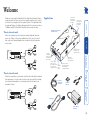
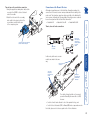
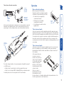
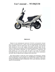
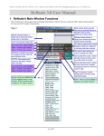
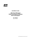
AdderLink X-Series Dual Video Transmitter Further information Troubleshooting.........................................................................11 Getting assistance.......................................................................11 Other products in the X-Series range........................................12 Warranty.....................................................................................12 Safety information.....................................................................12 Radio Frequency Energy............................................................13 European EMC directive 89/336/EEC.....................................13 FCC Compliance Statement (United States).........................13 Canadian Department of Communications RFI statement13 Installation....................................................................................3 Stage A - Configuration switch settings.................................3 Stage B - Mounting the module – desk or rack.....................4 Stage C – Connections.............................................................4 Installation Advice...............................................................4 Connections at the Dual Video Transmitter......................4 Connections at the Remote Receivers................................6 Operation......................................................................................7 Power and activity indicator...............................................7 ‘Two-in, two-out’ mode......................................................7 ‘One-in, two-out’ mode......................................................7 Installation and operation Password override........................................................................8 Flash upgrade...............................................................................8 Stage A - Download the upgrade files...................................8 Stage B - Create a startup diskette.........................................9 Stage C – Reconfigure the connections and begin................9 Stage D - Return the connections to their usual state........10 ‘One-in, two-out’ mode...........................................................2 ‘Two-in, two-out’ mode...........................................................2 Supplied items..........................................................................2 Special configuration F Welcome Contents Connection from the primary video controller within the computer Connection from the secondary video controller within the computer (if used) AdderLink X-Series Dual Video Transmitter module Allows one computer to be accessed by two separate keyboard, video and mouse sets. Control of the system is arbitrated on a ‘first come, first served’ basis, with control being relinquished two seconds after the last keyboard or mouse action. Twisted pair connection to primary (UTP 1) and secondary (UTP 2) remote receivers Socket for Y-cable to which connections from the keyboard and mouse ports of the computer are attached Expansion connector for future use and optional power input Switch bank to determine certain modes and functions Power and signal activity indicator Optional connection to power adapter (required when no keyboard connection will be made ‘Two-in, two-out’ mode When the computer has a second video controller, this mode allows a keyboard, video and mouse set to form a remote control connection, while the secondary video channel is transmitted to a second video monitor in the same (or an alternative) location. Y-cable Self-adhesive rubber feet F 2 x PS/2 style (keyboard and mouse) cables ‘One-in, two-out’ mode Supplied items Thank you for choosing the AdderLink X-Series Dual Video Transmitter. Used in conjunction with two remote receivers, this compact unit allows you to control (or monitor) one computer from two separate locations. The long distance links are made via Category 5 or higher cabling and each of the two spurs can be up to 200m in length. The Dual Video Transmitter can be used in two ways: Welcome 2 x video cables Power supply plus mains cable Installation and operation OFF: Normal operation ON: Transparent mode OFF: Normal operation ON: Flash upgrade/reset password modes OFF: Normal operation ON: Reset Dual Video Transmitter OFF: Two-in, two-out mode ON: One-in, two-out mode Note: When shipped, all switches are set in the OFF positions and this will produce normal operation in the ‘Two-in, two-out’ mode. To select the alternative, ‘One-in, two-out’ mode, simply change switch 3 to the ON position. Switch 3 OFF: ‘Two-in, two-out’ mode. Use this setting when the computer has a second video controller that must be fed to a second video monitor alongside, or separate from, the primary monitor, keyboard and mouse. ON: ‘One-in, two-out’ mode. Use this setting when two separate keyboard, video and mouse sets are required to control one computer. Switch 4 OFF: Normal operation. ON: Suspend operation and reset the Dual Video Transmitter. Use this setting momentarily to produce the same effect as removing and restoring power if incorrect operation has occurred. Return the switch to the OFF position to allow normal operation to continue. Switch 2 OFF: Normal operation. ON: Set transparent mode. Use this setting if the Dual Video Transmitter is to be used with KVM switches that are not manufactured by Adder Technology. Cascaded KVM switches often use special signals to set or identify conditions. In transparent mode, the Dual Video Transmitter will pass the signals without attempting to interpret them. The basic operation of the Dual Video Transmitter is controlled by the bank of four switches located on the side of the module. The switches are monitored at all times and may be changed when power is on or off (the only exception to this rule is switch 1 which initiates slightly different functions depending on the power state when it is switched). Stage A - Configuration switch settings Switch 1 OFF: Normal operation. ON: (Before power is applied) Places the module into upgrade mode so that the internal software can be changed. Please see the ‘Flash upgrade’ section in the ‘Special configuration’ section. ON: (Whilst power is applied) Places the connected receiver modules into password override mode. This allows any pre-configured passwords to be altered - particularly useful when they have been lost or forgotten. Please see the ‘Password override’ section in the ‘Special configuration’ chapter. F The installation of the Dual Video Transmitter is straightforward and can best be achieved in most cases by following these stages: • Stage A Check or set the configuration switch settings • Stage B Mount the module • Stage C Connect the cables Installation Stage B - Mounting the module – desk or rack Stage C – Connections The Dual Video Transmitter can be situated on a desk (or floor) or alternatively, for larger installations, mounted within an optional rack mount chassis. Desk mount Apply the supplied self-adhesive rubber feet to the underside of the module. Most connections to the Dual Video Transmitter are common to both of the operational modes, while other connections differ depending on whether the ‘Two-in, two-out’ or ‘One-in, two-out’ modes are selected. Pan-head screw Countersunk screws x 2 5 Use the third (pan-head) screw, in the top hole of the rack securing plate to fasten the module to the rack. Power connection The Dual Video Transmitter can obtain its power perfectly well from its keyboard connection to the computer system. Thus, if the keyboard connection is made to the computer, the power adapter is not necessary. If, however, the Dual Video Transmitter will not use a keyboard connection, then the power supply must be used: 1 Attach the output connector of the power supply to the socket at the front edge of the module labelled POWER. 2 Insert the IEC connector of the supplied power lead into the corresponding socket of the power supply. Connect the other end of the power lead to a nearby mains socket. When power is applied, either via the keyboard connector or power supply, the small indicator situated on the front edge of the module adjacent the POWER socket will glow red. Note: It is also possible to supply power to the module using the Expansion connector situated adjacent to the configuration switches. The use of this connector is beyond the scope of this user guide. Note: The module contains an internal automatic cut-out fuse to protect against power surges. To reset, remove power from the module for one second and then reconnect. Connections at the Dual Video Transmitter F Rack mount Note: The module switches are not accessible once it is inserted into the rack, therefore, check all settings before insertion. 1 Place the rack securing plate (available as a separate kit) onto the front of the module and secure it with the two countersunk screws. 2 Orient the Dual Video Transmitter module on its side so that its labelled face is the correct way up and the two blue video connectors are facing into the rack. 3 Slide the module into the required rack position. The rectangular cut-out in the front upper lip of the rack allows the two screws on the module’s upper edge to slide through. 4 The rack mount chassis has a series of holes in its floor that are spaced to accommodate the two screws on the module’s lower edge. Ensure that the screws correctly locate into the two holes of the chosen slot. The rack securing plate on the module should now be flush with the front of the rack Rack securing mount chassis. plate For correct operation, the local and remote units must have ground connections. At the computer end, this is achieved by ensuring that the computer or KVM switch that the AdderLink is connected to has a ground connection. At the keyboard / monitor / mouse end, this can be achieved by ensuring that the AdderLink’s power supply is connected to a grounded power outlet. Alternatively, a ground connection will be made via the monitor, if the monitor is itself grounded. Try to avoid laying the interconnect cable alongside power cables where possible. Installation Advice Supplied Y-cable Connection from the mouse port of the computer • Attach the blue video connector to the VIDEO 1 socket at the back end of the module. When rack-mounted, a route from the front to the rear of the module must be maintained for this connection to be possible. 3 At the other end of the three cables, attach the keyboard, mouse and video connectors to the appropriate sockets Connection from the primary video controller at the rear of the within the computer computer system. Note: For computers equipped with two video controllers, the video connection cable should go to the output socket of the primary controller. These are all of the connections required at the Dual Video Transmitter end if you are using the ‘One-in, two-out’ mode (Switch 3: ON) – Now go to the subsection ‘Connections at the Remote Receivers’. However, if you are using the ‘Two-in, two-out’ mode (Switch 3: OFF), one further connection must be made at the Dual Video Transmitter end - shown overleaf. Connection from the keyboard port of the computer Y-cable & KVM cable connections The Dual Video Transmitter uses a Y-cable to split-out the keyboard and mouse connections from the single socket on the front end of the module. 1 Insert the main plug of the Y-cable into the round socket labelled on the front edge of the module. 2 Using the supplied KVM cable: • Attach one of the supplied PS/2-style cables to the Y-cable socket labelled . • Attach the other supplied PS/2-style cable to the Y-cable socket labelled (mouse). If the computer has a 5-pin DIN (AT) keyboard connection, use an optional ‘PS/2 to AT’ converter (Adder Technology part code: VSA2). F Twisted pair cable connections The Dual Video Transmitter uses two twisted pair cables (Category Connection to primary 5 or higher) to link to the two remote receiver separate remote receiver units. Insert the connectors from the two twisted pair cables into the connectors front end of the module. Connection Note: In the ‘Two-in, to secondary two-out’ mode, remote receiver the UTP 1 connector provides keyboard, video and mouse data, while the UTP 2 connector supplies only a secondary video signal. ‘One-in, two-out’ mode connections Both receivers have keyboards, video monitors and mice attached in the same manner Single video connection In this mode, both remote receiver modules are wired in the same way: Power supply connection Connections to keyboard, mouse and video monitor Twisted pair connection from the Dual Video Transmitter The switch settings should be set for normal operation. Generally this means all set to OFF, however: • Switches 2 and 3 can be altered to select the required hot keys, and • Switch 4 selects Automatic (OFF) or Manual (ON) video compensation mode. For details, please refer to the user guide for the X-Series Extenders. Connection from the secondary video controller within the computer Although not supplied as part of the Dual Video Transmitter package, the connection of the remote receivers are important and differ according to the mode used. The instructions given here relate specifically to the AdderLink XSeries receivers, although the following Adder Technology receivers could also be used in conjunction with the Dual Video Transmitter: • AdderLink XR • AdderLink Silver XR • AdderLink Gold XR Connections at the Remote Receivers F ‘Two-in, two-out’ second video connection 1 Using the supplied secondary video cable, attach one end to the VIDEO 2 socket at the back end of the module. 2 Attach the other end of the secondary video cable to the output socket of the second video controller at the rear of the computer system. Operation ‘Two-in, two-out’ mode In this mode, operation should be straightforward with the main video image appearing on the monitor connected to the primary receiver. The keyboard and mouse connected at the primary receiver will have total control over the system. The output from the computer’s second video controller should then appear on the monitor connected to the secondary receiver. If there is no image on the secondary monitor, first check that the computer is actually generating a second screen image. Power supply connection Connection to secondary video monitor Second twisted pair connection from the Dual Video Transmitter The switch settings should be set for normal operation. Generally this means all set to OFF, however: • Switches 2 and 3 can be altered to select the required hot keys, and • Switch 4 selects Automatic (OFF) or Manual (ON) video compensation mode. For details, please refer to the user guide for the X-Series Extenders. ‘One-in, two-out’ mode In this mode, control of the computer is arbitrated on a first come, first served basis. In the standby state, control is available to both receivers and their keyboard indicators both show their current Num Lock, Caps Lock and Scroll Lock conditions. At the moment that a key is pressed or a mouse is moved on one receiver, the other receiver is temporarily locked out (the video image remains). The keyboard indicators on the locked out system then begin to flash to confirm its status: After two seconds of inactivity from the receiver that currently has control, the system returns to its standby condition and the keyboard indicators of the locked out system return to their ‘natural’ state. Recessed activity indicator In this mode, the primary and secondary remote receiver modules are connected differently. For the primary receiver, use the connection details shown on the previous page. For the secondary receiver, connect the module as shown here: On the front panel of the Dual Video Transmitter a small recessed indicator provides confirmation of power and activity, as follows: • Constant red - power applied, no communication activity. • Flickering red - power applied, communication occurring. • Slow flashing red - module is in flash upgrade mode. Primary receiver with keyboard, video monitor and mouse attached Primary and secondary video connections Power and activity indicator Secondary reciever with video monitor only attached F ‘Two-in, two-out’ mode connections Special configuration Stage A - Download the upgrade files To download the files 1 Access the Adder Technology Ltd website (www.adder.com), enter the Support section. Choose the upgrade option that best suits your requirements and download it to your system. 2 Decompress the downloaded file. Depending on the chosen option, there will be a collection of suitable files. As a minimum, there should be the following files: • AUTOEXEC.BAT – directs the computer to run the upgrade programs. • XKVMxxx.EXE – this is the upgrade program that causes upgrade data to be sent to the Dual Video Transmitter from the computer. • XDVTxxx.HEX – this is the firmware file for the Dual Video Transmitter. Where xxx is the upgrade version number. Now please follow Stage B. To override remote receiver passwords 1 Power down both remote receivers. Note: If you wish to leave one of the receivers unchanged, leave it switched off during this process – do not power the unit while the configuration switch on the Dual Video Transmitter is set. 2 With power to the Dual Video Transmitter still on, change switch 1 to the ON position. 3 Power on one or both of the remote receivers. The powered on receiver(s) will go directly into configuration mode so that new passwords may be set (without requiring the old one(s). For details about setting passwords, please refer to the user guide for the X-Series Extenders. 4 Once the remote receiver(s) have entered configuration mode, return switch 1 of the Dual Video Transmitter back to its OFF position. Note: If switch 1 remains ON, then the Dual Video Transmitter will enter upgrade mode when it is repowered and will not operate normally. This mode allows you to override any passwords that have been set at the remote receiver(s) and place them into configuration mode so that new ones may be set. This feature is particularly useful when passwords have been lost or forgotten. As part of the continual development and improvement process across the range of Adder products, software upgrades are occasionally made available. The Dual Video Transmitter’s internal flash memory and Adder’s unique keyboard-link upgrade technique allow you to utilise software upgrades in a straightforward manner. Note: X-Series receiver modules can also be flash upgraded. For further details, please refer to the user guide for the X-Series Extenders. To perform a flash memory upgrade, you need to perform the following stages: • Stage A – Download upgrade files from the Adder website • Stage B – Create a startup diskette and copy the files to it • Stage C – Reconfigure the connections and begin • Stage D - Return the connections to their usual state Password override Flash upgrade F In operation, the Dual Video Transmitter is generally an unseen and transparent element in the system. Most of the configurable options and usability settings (such as passwords, hotkey controls, etc.) are made at the receiver units, where the keyboards, video monitors and mice are connected. There are, however, two important configuration options particular to the Dual Video Transmitter, both of which are controlled by switch 1 on its side panel. To create a startup disk in Windows 95/98 (alternative method) 1 Insert a diskette into the floppy disk drive. 2 Right mouse click on the ‘3½ Floppy (A:)’ icon and select ‘Format’. 3 Select the ‘Full format’ option and ensure that the ‘Copy system files’ box is checked. 4 Select ‘Start’ to format the disk. To create a startup disk from MS-DOS or a DOS window within Windows 95/98 1 Insert a diskette into the floppy disk drive and check that the drive is configured as drive A (it usually is). 2 At the DOS prompt (C:\>) type: FORMAT A: /S and follow the instructions given by DOS. Copy the downloaded files to the disk Once the diskette has been formatted, using Windows Explorer or the My Computer option, copy the downloaded and decompressed files from your computer to the floppy diskette. Now please follow Stage D. To create a startup disk in Windows 95/98/Me 1 Insert a formatted diskette into the floppy disk drive. 2 Select ‘Start’, then ‘Settings’ and then ‘Control Panel’. 3 Double click on the ‘Add/Remove Programs’ icon. 4 Select the ‘Startup Disk’ tab. 5 Click ‘Create Disk’ and follow the instructions. 1 On the computer from which you will run the upgrade, ensure that its BIOS settings will allow it to boot from the floppy diskette drive, rather than booting immediately from the hard drive. 2 Switch off the computer and Dual Video Transmitter (if a power supply is connected). 3 Disconnect both twisted pair cables from the Dual Video Transmitter. For the upgrade process, the only connection that is essential, between the computer and the Dual Video Transmitter, is the keyboard port connection. 4 So that you can check upgrade progress, connect a monitor directly to the primary video port of the computer. Remove the twisted pair 5 On the Dual Video connections and ensure that the link to the computer’s keyboard Transmitter, change port is correct - the mouse and video port connections are switch 1 to the ON unimportant for this operation position. Ensure that the upgrade diskette is in the floppy disk drive of the computer. 6 Power on the computer (and Dual Video Transmitter, if it is using the power adapter). The upgrade process will start automatically and confirmation will be given on screen. To create a startup disk in Windows XP 1 Insert a diskette into the floppy disk drive. 2 Select ‘Start’ and then ‘My Computer’. 3 Right mouse click on the ‘3½ Floppy (A:)’ icon and select ‘Format’. 4 Check the ‘Create an MS-DOS startup disk’ box and select ‘Start’. Stage C – Reconfigure the connections and begin For this stage you will need a 3½ floppy diskette that is either blank or has existing contents that are no longer required. The write protect tab must be moved to the ‘unprotected’ position. Depending on your operating system, use one of the following to create a startup disk: F Stage B - Create a startup diskette Now please follow Stage C. F Once the upgrade process has been completed, perform the following to return the system to its previous state. 1 Switch off the computer and Dual Video Transmitter (if a power supply is connected). 2 On the Dual Video Transmitter, change switch 1 to the OFF position. 3 Reinstate the twisted pair connections and also the video connection(s) between the Dual Video Transmitter and the computer. 4 Remove the diskette from the system and reboot. Stage D - Return the connections to their usual state 10 In ‘two-in, two-out’ mode no video image is received on the second screen. • Temporarily disconnect the second video link to the Dual Video Transmitter, connect a monitor directly to the computer secondary video port and check for a correct video image output on this channel. Power is applied via the power supply but Dual Video Transmitter (or remote receiver) operation has stopped. • Each module has an internal automatic cut-out fuse to protect against power surges. To reset, remove power from the module for one second and then reconnect. Getting assistance If you are still experiencing problems after checking the list of solutions in the Troubleshooting section then we provide a number of other solutions: • Adder Technology website – www.adder.com Check the Support section of our website for the latest solutions and driver files. • Email – [email protected] • Fax in the UK: in the US: 01954 780081 +1 888 275 1117 • Phone in the UK: in the US: 01954 780044 +1 888 275 3337 Video image at the remote receiver is distorted or shadows appear to the right of displayed objects. Video compensation is required to overcome the delay effects of long twisted pair wiring, especially when running through a patch panel. If video problems persist: • All X-series receivers contain automatic circuitry to overcome all but the most severe cases. If an X-Series receiver fails to automatically correct a video problem, try adjusting it manually. For details about manual video compensation, please refer to the user guide for the X-Series Extenders. • For non X-Series receivers (which do not have automatic video compensation), manual video compensation should be performed. Please refer to the user guide for the receiver. • If your video image has coloured shadows you may need to use the optional X-Series Skew Compensator. This stand-alone passive module allows you to finely tune the red, green and blue video signal timings (each of which is fed along separate twisted pair sets) to overcome most screen image problems. No video image is received at either of the remote receivers. • Check that the power/activity indicators are lit on the Dual Video Transmitter as well as the receivers - if they are not, then there is a power problem. When keys are pressed or the mouse is moved, check that the indicators flicker – if they do not then there could be a twisted pair link problem or a problem with one of the modules. • If possible, try using an alternative twisted pair connection between the Dual Video Transmitter and the receiver. • If the receiver is severely over compensated, the monitor may not be able to display a picture. Try manually reducing the video compensation. Please refer to the user guide for the receiver. • Temporarily disconnect the video link to the Dual Video Transmitter, connect a monitor directly to the computer video port and check for a correct video image output. If you experience problems when installing or using the Dual Video Transmitter, please check through this section for a possible solution. If your problem is not listed here and you cannot resolve the issue, then please refer to the ‘Getting assistance’ section. Troubleshooting Further information 11 Warranty Adder Technology Ltd warrants that this product shall be free from defects in workmanship and materials for a period of two years from the date of original purchase. If the product should fail to operate correctly in normal use during the warranty period, Adder will replace or repair it free of charge. No liability can be accepted for damage due to misuse or circumstances outside Adder’s control. Also Adder will not be responsible for any loss, damage or injury arising directly or indirectly from the use of this product. Adder’s total liability under the terms of this warranty shall in all circumstances be limited to the replacement value of this product. If any difficulty is experienced in the installation or use of this product that you are unable to resolve, please contact your supplier. • For use in dry, oil free indoor environments only. • Do not use to link between buildings. • Ensure that the twisted pair interconnect cable is installed in compliance with all applicable wiring regulations. • Do not connect the CATx link interface (RJ45 style connector) to any other equipment, particularly network or telecommunications equipment. • Warning – the power adapter contains live parts. • No user serviceable parts are contained within the power adapter - do not dismantle. • Plug the power adapter into a socket outlet close to the AdderLink unit that it is powering. • Replace the power adapter with a manufacturer approved type only. • Do not use the power adapter if the power adapter case becomes damaged, cracked or broken or if you suspect that it is not operating properly. • If you use a power extension cord with the AdderLink, make sure the total ampere rating of the devices plugged into the extension cord do not exceed the cord’s ampere rating. Also, make sure that the total ampere rating of all the devices plugged into the wall outlet does not exceed the wall outlet’s ampere rating. • Do not attempt to service the AdderLink yourself. • The AdderLink units and power supplies can get warm in operation – do not situate them in an enclosed space without any ventilation. • The AdderLink does not provide ground isolation and should not be used for any applications that require ground isolation or galvanic isolation. The following related X-Series items are available: • Remote receiver module (part code: X-KVM/R) Two of these are required, one at the end of both remote cable spurs emanating from the Dual Video Transmitter. These modules convert the coded signals from the Dual Video Transmitter back into native formats used by keyboards, video monitors and mice. • Skew compensator (part code: X-SC) Removes colour split in video signals caused by certain Cat 5e and 6 cables. Required only in certain installations with long cable lengths and high video resolutions. • Rack mount chassis (part code: RMK-CHASSIS) This 19” chassis allows multiple X-Series modules to be neatly arranged within a standard cabinet. Securing plates and screws are supplied separately for each X-Series module for use with the rack mount chassis. • Power distribution module (part code: X-PDM4) Provides power for up to four X-Series modules to reduce mains power socket requirements. • Rack mount securing plates • for Dual Video Transmitter (part code: X-RMK-DVT) • for remote receiver (part code: X-RMK-KVM/R) • for Skew compensator (part code: X-RMK-SC) • single slot blanking plate (part code: X-RMK-BLANK) • quad slot blanking plate (part code: X-RMK-BLANK4) Safety information Other products in the X-Series range 12 Canadian Department of Communications RFI statement This equipment does not exceed the class A limits for radio noise emissions from digital apparatus set out in the radio interference regulations of the Canadian Department of Communications. Le présent appareil numérique n’émet pas de bruits radioélectriques dépassant les limites applicables aux appareils numériques de la classe A prescrites dans le règlement sur le brouillage radioélectriques publié par le ministère des Communications du Canada. This equipment generates, uses and can radiate radio frequency energy and if not installed and used properly, that is, in strict accordance with the manufacturer’s instructions, may cause interference to radio communication. It has been tested and found to comply with the limits for a class A computing device in accordance with the specifications in Subpart J of part 15 of FCC rules, which are designed to provide reasonable protection against such interference when the equipment is operated in a commercial environment. Operation of this equipment in a residential area may cause interference, in which case the user at his own expense will be required to take whatever measures may be necessary to correct the interference. Changes or modifications not expressly approved by the manufacturer could void the user’s authority to operate the equipment. This equipment has been tested and found to comply with the limits for a class A computing device in accordance with the specifications in the European standard EN55022. These limits are designed to provide reasonable protection against harmful interference. This equipment generates, uses and can radiate radio frequency energy and if not installed and used in accordance with the instructions may cause harmful interference to radio or television reception. However, there is no guarantee that harmful interference will not occur in a particular installation. If this equipment does cause interference to radio or television reception, which can be determined by turning the equipment on and off, the user is encouraged to correct the interference with one or more of the following measures: (a) Reorient or relocate the receiving antenna. (b) Increase the separation between the equipment and the receiver. (c) Connect the equipment to an outlet on a circuit different from that to which the receiver is connected. (d) Consult the supplier or an experienced radio/TV technician for help. FCC Compliance Statement (United States) European EMC directive 89/336/EEC A Category 5 (or better) twisted pair cable must be used to connect the AdderLink units in order to maintain compliance with radio frequency energy emission regulations and ensure a suitably high level of immunity to electromagnetic disturbances. All other interface cables used with this equipment must be shielded in order to maintain compliance with radio frequency energy emission regulations and ensure a suitably high level of immunity to electromagnetic disturbances. Radio Frequency Energy 13 Tel: +44 (0)1954 780044 Fax: +44 (0)1954 780081 Tel: +1-888-932-3337 Fax: +1-888-275-1117 Adder Corporation, 29 Water Street, Newburyport, MA 01950, United States of America Adder Technology Limited, Technology House, Trafalgar Way, Cambridge, CB3 8SQ, United Kingdom © 2007 Adder Technology Limited All trademarks are acknowledged. Release 1.0d July 2007 Part No. ADD0048/1 14