1
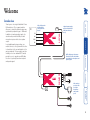
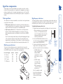
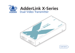
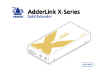
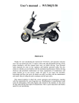
AdderLink X-Series USB Extender ER W PO ON ST HO K LIN IO O T R E M T O E D AU B+ US DEO VI ® R DE LO C AL IE SER m r.co de d w.a ww S AD Further information Troubleshooting ........................................................................14 Getting assistance......................................................................14 Radio Frequency Energy ...........................................................16 Mounting a module – desk or rack ............................................4 Connections .................................................................................5 Connections at the LOCAL module........................................5 Video ...................................................................................5 USB .....................................................................................6 Audio ..................................................................................6 Link connection(s) ..............................................................7 Optional power supply ......................................................7 Connections at the REMOTE module ....................................8 Video monitor ....................................................................8 USB devices (including keyboard & mouse)......................8 Audio connections .............................................................9 Link connection(s) ..............................................................9 Power supply ....................................................................10 Installation General use ................................................................................11 Power surge fuses......................................................................11 Power and activity indicators....................................................11 Signal loss compensation ..........................................................12 Video signal boost ................................................................12 Multi frequency video boost ...........................................12 High frequency video boost ............................................12 Microphone signal boost......................................................13 Introduction ................................................................................2 Supplied items .............................................................................3 Operation Welcome Contents 1 Welcome Optional power supply unit (not needed when USB connection to PC used) SERIES VIDEO USB MIC CAT-5 cabling up to 100 metres: First cable for video & USB data Second cable for microphone and speaker signals SERIES PSU USB 1 USB 2 USB 3 USB 4 Video monitor port, four USB ports, plus microphone and speaker ports. SPK PSU LOCAL PC Video, USB, speaker and microphone connections from host PC REMOTE Thank you for choosing the AdderLink X-Series USB extender set. These compact modules allow you to extend the distance between any system and its peripherals by up to 100 metres. In addition to transferring video signals, the extender units provide four USB ports and microphone input as well as stereo speaker output. In a straightforward setup procedure, one module connects to the system while the other is situated next to the user and attaches to the various peripherals. The two modules are then linked by one or two standard CAT-5 twisted pair cables: one to carry video and USB data, the other to (optionally) transfer microphone and speaker signals. Introduction 2 Supplied items Optional power supply connection Operation indicators HO ST K LIN Connections to REMOTE module IO O T E T O M E R D AU S L de d w.a m r.co E DD ® R Video cable LOCAL extender module ww Connection to PC microphone and speaker ports Operation indicators E O N P O W L IN K A L C TO LO Connections for microphone and speakers V US ID B E + O A U D IO C O M P E N S A T IO N Option switches M O T E E DD S S ERIE Connections to LOCAL module USB cable Power supply plus mains cable ® R A R E Video compensation adjustment Power supply connection Connection to PC USB port R Connection to PC video output Self adhesive rubber feet CA LO A S ERIE B+ US EO VID ON ER W PO m r.co de d w.a ww Connection to video monitor REMOTE extender module Audio cable Four USB (v1.1) ports 3 Installation The installation of the USB Extender set is straightforward and can best be achieved in most cases by following these stages for each module: • Mount the module • Connect the cables Mounting a module – desk or rack Rack mount Note: The module switches are not accessible once it is inserted into the rack, therefore, check all settings before insertion. 1 Place the rack securing plate (available as a separate kit) onto the front of the module and secure it with the two countersunk screws. 2 Orient the module on its side so that its labelled face is the correct way up and the securing plate is facing away from the rack. 3 Slide the module into the required rack position. The rectangular cut-out in the front upper lip of the rack allows the two screws on the module’s upper edge to slide through. 4 The rack mount chassis has a series of holes in its floor that are spaced to accommodate the two screws on the module’s lower edge. Ensure that the screws correctly locate into the two holes of the chosen slot. The rack securing plate on the module should now be flush with the front of the rack mount chassis. 5 Use the third (pan-head) screw, in the top hole of the rack securing plate to fasten the module to the rack. 1 2 34 ON Desk mount Apply the supplied self-adhesive rubber feet to the underside of the module(s). The USB Extender modules can be situated on a desk (or floor) or alternatively, for larger installations, mounted within optional rack mount chassis units. 4 Connections LOCAL Module connects to the PC SERIES User SERIES REMOTE PC LOCAL The naming of the LOCAL and REMOTE modules relate to their proximity to the computer system. REMOTE Module connects to the peripherals by the user Video 1 Locate the supplied video cable and attach one end to the connector marked on the LOCAL module. When using the full capabilities of the X-Series USB extender modules, the following connections are made to the LOCAL module: • Video - see right • USB • Audio • Twisted pair link(s) • Optional power supply Cables can be attached in any order, not necessarily the order shown in this section. Note: Wherever possible, ensure that the PC system is switched off when connecting cables. Connections at the LOCAL module Hence, the LOCAL module connects directly to the system, while the REMOTE is at the other end of the twisted pair cable(s) and attaches to the video monitor, USB peripherals and sound equipment. • For correct operation, the local and remote units must have ground connections. At the computer end, this is achieved by ensuring that the computer or KVM switch that the AdderLink is connected to has a ground connection. At the keyboard / monitor / mouse end, this can be achieved by ensuring that the AdderLink’s power supply is connected to a grounded power outlet. Alternatively, a ground connection will be made via the monitor, if the monitor is itself grounded. • Try to avoid laying the interconnect cable alongside power cables where possible. 2 Attach the other end of the video cable to the video output port of the host PC. Installation Advice 5 USB Audio 1 Locate the supplied audio cable and attach one end to the required jack socket marked (speaker) or (microphone) on the LOCAL module (if you need to simultaneously use the speaker and microphone connections, a second audio link cable will be needed). 2 Insert the plug at the other end of the audio cable to appropriate socket on the PC system: • Microphone sockets are often coloured pink • Speaker sockets are often coloured light green. 2 Attach the other end of the USB cable to one of the USB sockets of the host PC. Note: When connected to a USB port of the PC, the LOCAL module does not require the use of a power supply unit (the REMOTE module, however, always requires a power supply). 1 Locate the supplied USB cable and insert the smaller connector into the LOCAL module socket marked . 6 Optional power supply A power supply is only required by the LOCAL module when no USB connection is made to the USB port of the PC. 1 Attach the output connector of the power supply to the LOCAL module socket marked ‘POWER’. 2 Insert the IEC connector of the supplied power lead into the corresponding socket of the power supply. Connect the other end of the power lead to a nearby mains socket. Audio link cable Required only when using microphone and/or speakers. 1 Insert the connector from the secondary twisted pair cable link into the LOCAL module socket marked ‘AUDIO’. Video and USB link cable 1 Insert the connector from the primary twisted pair cable link into the LOCAL module socket marked ‘USB + VIDEO’. Links between the LOCAL and REMOTE modules are made via one (or two) twisted pair cables, specified to Category 5 or higher. Ensure that the total twisted pair cable length for each connection (including patch boxes) does not exceed 100 metres. • When extending only video and USB, only a single link cable is required. • When extending video, USB and audio signals, two link cables are required. Link connection(s) 7 Connections at the REMOTE module The REMOTE module contains a USB hub that provides four separate USB 1.1 channels. 1 Attach the leads from up to four USB devices to the REMOTE module sockets marked . USB devices . 1 Attach the lead from the monitor to the REMOTE module socket marked Video monitor When using the full capabilities of the X-Series USB extender modules, the following connections are made to the REMOTE module: • Video monitor - see below • USB devices - see below • Audio (microphone and speakers) • Link connection(s) • Power supply Cables can be attached in any order, not necessarily the order shown in this section. 8 Links between the REMOTE and LOCAL modules are made via one (or two) twisted pair cables, specified to Category 5 or higher. Ensure that the total twisted pair cable length for each connection (including patch boxes) does not exceed 100 metres. • When extending only video and USB, only a single link cable is required. • When extending video, USB and audio signals, two link cables are required. Video and USB link cable 1 Insert the connector from the primary twisted pair cable link into the REMOTE module socket marked ‘USB + VIDEO’. Link connection(s) Note: The REMOTE module provides a signal boost feature to assist with unresponsive microphones. See Microphone signal boost for details. Audio link cable Required only when using microphone and/or speakers. 1 Insert the connector from the secondary twisted pair cable link into the REMOTE module socket marked ‘AUDIO’. Audio connections are available at the two 3.5” jack sockets mounted on the side (same side as the switch bank) of the REMOTE module. Note: When the REMOTE module is rack mounted, audio connections must be made after the module has been fixed in place. Access is required to the rear and above the rack. Remember to remove any audio connections before attempting to slide out the REMOTE module. 1 Make the required audio connections according to the corresponding connection(s) at the LOCAL module. • Microphone connections are made to the REMOTE module socket marked • Speaker connections are made to the REMOTE module socket marked Audio connections 9 Power supply 2 Insert the IEC connector of the supplied power lead into the corresponding socket of the power supply. Connect the other end of the power lead to a nearby mains socket. A power supply is always required by the REMOTE module. 1 Attach the output connector of the power supply to the REMOTE module socket marked ‘POWER’. 10 Operation PO W ON Power surge fuses HO Both modules contain internal automatic cut-out fuses to protect against power surges. ST LIN K AU D TO REMOTE If a module stops responding • Check whether the module’s ON indicator is lit. If the ON indicator is lit, then the problem is unlikely to be power related, check all the connections. • If the module ON indicator is not lit, check the indicator on its power supply, or for the LOCAL module, check that the PC is operating and the USB link is still connected. • If the power supply indicator is lit, or the PC is operating (with the USB link intact), then the anti-surge surge fuse may have been tripped. Reset the anti-surge fuse, as detailed next. ER IO ER® HOST Lit whenever a USB host (PC) is connected and at least one device is attached at the REMOTE module. This indicator will flicker when an active PC host is connected, but will darken if there is no remote USB device. LINK Lit when a physical link exists between the LOCAL and REMOTE modules. U VI SB+ DE O REMOTE module To reset an anti-surge fuse Remove the power connection (or, for an unpowered LOCAL module, the USB connection) from the module for one second and then reconnect. PO W CO MP ER ON EN SA TI ON LIN TO LOCAL K ER® AU D IO U VI SB+ DE O ON Lit whenever power from the power supply is present. LINK Lit whenever a USB host (PC) is connected at the LOCAL module and at least one device is attached at the REMOTE module. This indicator will flicker when an active PC host is connected, but will darken if there is no USB device connected at the REMOTE module. ON Lit whenever power (from the PC USB port or optional power supply) is present. LOCAL module The front panels of both modules feature recessed indicators to provide confirmation of power and activity. In use, the USB Extender modules should be transparent - the system and its peripherals should operate exactly as normal, the only difference being that they are now up to 100 metres apart. In some installations, you may see some ‘shadows’ to the right of high contrast screen characters. This can be caused by signal loss over long distances (or low quality link cables) or by incorrect video signal compensation settings - see the Signal loss compensation section for details. Power and activity indicators General use 11 Signal loss compensation Multi frequency video boost The function of the multi frequency boost is rather like that of a monitor’s contrast control. It should be set to according to the preference of the user, but these REMOTE module switch settings offers a rough guideline: Switch 3 OFF ON OFF ON O ON N 1 PO W 2 34 CO M PE ER ON NS AT I ON LIN ON 1 2 34 AU D K IO U VI SB+ DE O Switch 2 OFF OFF ON ON To adjust high frequency video boost 1 Display a high contrast image with vertical edges on the remote monitor: • Open a word processor, type the capital letter ‘H’, or ‘M’ and increase the point size to 72 or higher. For best results, the background should be white and the character should be black. 2 Insert a small flat-bladed screwdriver into the White or black slot of the small recessed dial on the REMOTE High contrast black character shadow on module, marked ‘COMPENSATION’. on white right side background - indicates 3 Slowly turn the dial while viewing the screen the need for adjustment image, until the vertical edges of the test pattern are crisp and clear with no shadowing: • A BLACK shadow to the right of the character indicates UNDER compensation - turn the dial clockwise to increase boost. Turn • A WHITE shadow clockwise to the right of the to increase character indicates boost OVER compensation Turn anti- turn anti-clockwise to clockwise to decrease boost. decrease Note: If you apply too much ER® boost boost, the monitor may go blank. Turn the dial anticlockwise until the image returns. TO LOCAL Link cable length 0 - 25 metres 25 - 50 metres 50 - 75 metres 75 - 100 metres This feature provides an extra boost for high frequency video signals which are most greatly affected by cable losses. Before using this feature, ensure that the multi frequency boost has been set for the approximate cable length. High frequency video boost Two separate boost features are available to ensure that the video signal remains as crisp and clear as possible: • Multi frequency video boost - this feature boosts all video frequencies to counter the general effects of long cable runs. This boost feature is adjusted using the small switches along the side of the REMOTE module. • High frequency video boost - this feature affects only the higher video frequencies that face additional degradation over long spans. This boost feature is adjusted using the recessed dial at the front end of the REMOTE module. Note: If the video image remains fuzzy or distorted after applying both types of boost, then there may be a ‘skew’ problem. This is caused by uneven lengths within the twisted pairs of the link cables. To rectify such a problem you may need to install an Adder Skew Compensator (part number: X-SC). Video signal boost Analog signals such as video and audio are susceptible to the effects of cable resistance. When transmitted over long distances the degradations can begin to produce noticeable results. To maintain a high quality service, the X-Series USB extender modules feature both video and microphone signal loss compensation features. 12 Microphone signal boost Switch 1 OFF ON O ON N 1 4 1 2 34 Note: Switch 4 is reserved for future use and currently has no function. It should remain switched OFF. ON Microphone signal boost Disabled Enabled Most microphones function perfectly well with the standard amplification provided by the X-Series USB extenders, however, less responsive microphones may require an extra boost. This feature boosts the microphone signal by roughly ten times. 13 Further information Troubleshooting Sound from the microphone cannot be heard or is very quiet • Try changing the setting of REMOTE module switch 1 to ON. Getting assistance If you are still experiencing problems after checking the list of solutions in the Troubleshooting section then we provide a number of other solutions: • Adder Technology website – www.adder.com Check the Support section of our website for the latest solutions. • Email [email protected] • Fax in the UK: in the US: 01954 780081 +1 888 275 1117 • Phone in the UK: in the US: 01954 780044 +1 888 275 3337 Power is applied via the power supply but REMOTE module operation has stopped. • Each module has an internal automatic cut-out fuse to protect against power surges. To reset, remove power from the module for one second and then reconnect. To reset an unpowered LOCAL module, remove and then replace the USB connection. See the Power surge fuses section for details. No video image is received at the REMOTE module. • Check that the power/activity indicators are lit on the LOCAL and REMOTE modules - if they are not, then there is a power problem. • If the REMOTE module is severely over compensated, the monitor may not be able to display a picture. Try using a small flat-bladed screwdriver to turn the recessed dial anti-clockwise to reduce the video compensation. See the Video signal boost section for details. • Check that the USB + VIDEO link cable (Category 5 or higher) is wired correctly. See the Connections section for details. • If possible, try using an alternative USB + VIDEO link cable between the modules. • Temporarily disconnect the video link to the LOCAL module, connect a monitor directly to the computer video port and check for a correct video image output. USB devices work intermittently or not at all • Check that the link cables do not exceed 100 metres in length (including patch boxes). Longer cable runs will induce errors that disturb USB operation. • If possible, try a different link cable to see whether operation returns to normal. • Minimise close contact of the link cables with other cables or devices carrying high voltages. Such sources can induce interference into the link cable. Video image at the REMOTE module is distorted or shadows appear to the right of displayed objects. Video compensation is required to adjust for the length of the link cable being used. If video problems persist: • Please refer to the Video signal boost section. • If the overall video image is ‘fuzzy’ and/or has coloured shadows you may need to use the optional X-Series Skew Compensator (part number: X-SC). This standalone passive module allows you to finely tune the red, green and blue video signal timings (each of which is fed along separate twisted pairs) to overcome most colour separation problems. If you experience problems when installing or using the X-Series USB extender modules, please check through this section for a possible solution. If your problem is not listed here and you cannot resolve the issue, then please refer to the ‘Getting assistance’ section. 14 Warranty Adder Technology Ltd warrants that this product shall be free from defects in workmanship and materials for a period of two years from the date of original purchase. If the product should fail to operate correctly in normal use during the warranty period, Adder will replace or repair it free of charge. No liability can be accepted for damage due to misuse or circumstances outside Adder’s control. Also Adder will not be responsible for any loss, damage or injury arising directly or indirectly from the use of this product. Adder’s total liability under the terms of this warranty shall in all circumstances be limited to the replacement value of this product. If any difficulty is experienced in the installation or use of this product that you are unable to resolve, please contact your supplier. • For use in dry, oil free indoor environments only. • Do not use to link between buildings. • Ensure that the twisted pair interconnect cable is installed in compliance with all applicable wiring regulations. • Do not connect the CATx link interface (RJ45 style connector) to any other equipment, particularly network or telecommunications equipment. • Warning – the power adapter contains live parts. • No user serviceable parts are contained within the power adapter - do not dismantle. • Plug the power adapter into a socket outlet close to the AdderLink unit that it is powering. • Replace the power adapter with a manufacturer approved type only. • Do not use the power adapter if the power adapter case becomes damaged, cracked or broken or if you suspect that it is not operating properly. • If you use a power extension cord with the AdderLink, make sure the total ampere rating of the devices plugged into the extension cord do not exceed the cord’s ampere rating. Also, make sure that the total ampere rating of all the devices plugged into the wall outlet does not exceed the wall outlet’s ampere rating. • Do not attempt to service the AdderLink yourself. • The AdderLink units and power supplies can get warm in operation – do not situate them in an enclosed space without any ventilation. • The AdderLink does not provide ground isolation and should not be used for any applications that require ground isolation or galvanic isolation. Safety information The following related X-Series items are also available: • Gold Extender (part code: X-KVMAS) This pair of modules allow you to extend not only keyboard, video and mouse signals up to 200 metres, but also similarly support microphone, stereo speaker and an RS232 serial channel. • Dual video transmitter (part code: X-DVT) Allows one system to be controlled from two locations or permits a second video channel to be sent to a remote location. Used in conjunction with two standard receiver/remote modules. • Remote receiver module (part code: X-KVM/R) Two of these are required, one at the end of both remote cable spurs emanating from the Dual Video Transmitter. These modules convert the coded signals from the Dual Video Transmitter back into native formats used by keyboards, video monitors and mice. • Skew compensator (part code: X-SC) Removes colour split in video signals caused by certain Cat 5e and 6 cables. Required only in certain installations with long cable lengths and high video resolutions. • Rack mount chassis (part code: RMK-CHASSIS) This 19” chassis allows multiple X-Series modules to be neatly arranged within a standard cabinet. Securing plates and screws are supplied separately for each X-Series module for use with the rack mount chassis. • Power distribution module (part code: X-PDM4) Provides power for up to four X-Series modules to reduce mains power socket requirements. • Rack mount securing plates • for USB Extender (part code: X-RMK-USB) • for Gold Extender remote module (part code: X-RMK-KVMAS/R) • for Gold Extender local module (part code: X-RMK-KVMAS/T) • for Dual Video Transmitter (part code: X-RMK-DVT) • for Skew compensator (part code: X-RMK-SC) • single slot blanking plate (part code: X-RMK-BLANK) • quad slot blanking plate (part code: X-RMK-BLANK4) Other products in the X-Series range 15 Canadian Department of Communications RFI statement This equipment does not exceed the class A limits for radio noise emissions from digital apparatus set out in the radio interference regulations of the Canadian Department of Communications. Le présent appareil numérique n’émet pas de bruits radioélectriques dépassant les limites applicables aux appareils numériques de la classe A prescrites dans le règlement sur le brouillage radioélectriques publié par le ministère des Communications du Canada. This equipment generates, uses and can radiate radio frequency energy and if not installed and used properly, that is, in strict accordance with the manufacturer’s instructions, may cause interference to radio communication. It has been tested and found to comply with the limits for a class A computing device in accordance with the specifications in Subpart J of part 15 of FCC rules, which are designed to provide reasonable protection against such interference when the equipment is operated in a commercial environment. Operation of this equipment in a residential area may cause interference, in which case the user at his own expense will be required to take whatever measures may be necessary to correct the interference. Changes or modifications not expressly approved by the manufacturer could void the user’s authority to operate the equipment. This equipment has been tested and found to comply with the limits for a class A computing device in accordance with the specifications in the European standard EN55022. These limits are designed to provide reasonable protection against harmful interference. This equipment generates, uses and can radiate radio frequency energy and if not installed and used in accordance with the instructions may cause harmful interference to radio or television reception. However, there is no guarantee that harmful interference will not occur in a particular installation. If this equipment does cause interference to radio or television reception, which can be determined by turning the equipment on and off, the user is encouraged to correct the interference with one or more of the following measures: (a) Reorient or relocate the receiving antenna. (b) Increase the separation between the equipment and the receiver. (c) Connect the equipment to an outlet on a circuit different from that to which the receiver is connected. (d) Consult the supplier or an experienced radio/TV technician for help. FCC Compliance Statement (United States) European EMC directive 89/336/EEC A Category 5 (or better) twisted pair cable must be used to connect the AdderLink units in order to maintain compliance with radio frequency energy emission regulations and ensure a suitably high level of immunity to electromagnetic disturbances. All other interface cables used with this equipment must be shielded in order to maintain compliance with radio frequency energy emission regulations and ensure a suitably high level of immunity to electromagnetic disturbances. Radio Frequency Energy 16 Adder Corporation, 29 Water Street, Newburyport, MA 01950, United States of America Tel: +1-888-932-3337 Fax: +1-888-275-1117 Adder Technology Limited, Technology House, Trafalgar Way, Bar Hill, Cambridge, CB3 8SQ, United Kingdom Tel: +44 (0)1954 780044 Fax: +44 (0)1954 780081 © 2004 Adder Technology Limited All trademarks are acknowledged. Release 1.0d December 2004 Part No. ADD0055 Documentation by: www.ctxd.com 17