1
Mitsubishi Graphic Operation Terminal
Simply the best
G R A P H I C
O P E R A T I O N
It's not a mere display. It's a GOT.
T E R M I N A L
G O T 1 0 0 0
Mitsubishi Electric Corporation Nagoya Works and Himeji Works
are factories certified for ISO14001 (standards for environmental
management systems) and ISO9001 (standards for quality assurance management systems).
http://www.MitsubishiElectric.co.jp/english/
distributed by AA ELectric 1-800-237-8274 www.a-aelectric.com
EC97J1113
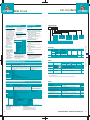
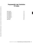
INDEX
Concept
Lineup
Features
2
4
6
Designer support
Operator support
Startup & adjustment support
Maintenance support
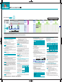
It's what we do. Coming up with answers. Breaking new ground.
And now it's here-the GOT1000-reflecting the next generation's vision.
Its beauty alone, its functionality alone, takes the GOT1000 beyond a mere "display". But what really sets it apart is the usability that was inspired by voices from actual worksites.
Connectable model list
22
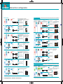
Connection configuration
BUS connection
Specification
External dimensions
Function list for each model
Notes for use
List of products
Sales & service network
25
How far can a display evolve when functions are inspired by the voices of actual users, rather than a race for that "new look"?
To answer this question, Mitsubishi drew on its technology and experience cultivated at actual FA worksites, and the resulting GOT1000 sets the standard for the next generation.
In addition to raising the level of display basics such as response, display, and connectivity, the GOT1000 is packed with ideas and functions designed to improve productivity and workability.
In short, the GOT1000 is about usability, and creating new value.
The GOT1000 not only gives customers improved connectivity to PLCs and a host of other FA devices, it provides a powerful competitive edge in the global market as well.
distributed by AA ELectric 1-800-237-8274 www.a-aelectric.com
Toward
a
unique
GOT
brand
The needs expressed by users will continue to be a central part of the GOT series
evolution to the next-generation display. Mitsubishi Electric's aims are summed up
by the slogan, "Simply the best!".
Simply the best
30
40
42
44
46
47
50
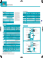
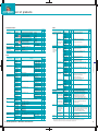
There's a model for your needs. The GOT1000 lineup is about usability.
Standard models offer a full array of basic functions for stand-alone use.
Full-spec models accommodate a wide range of applications in stand-alone or network environments.
GT11
GT15
'' Type
GT11
'' Type
GT11
GT1150-QLBD
GT1155-QSBD
STN monochrome
QVGA (320 x 240 dot)
Black & white 16-step adjustment
STN color
QVGA (320 x 240 dot)
256 colors
Features
Features
Black & white,
16-step adjustment
A-list editing
System monitor
256 colors
Transparent
USB
RS-232
CF card I/F
Memory 3M
Connection format*2
USB
RS-232
CF card I/F
Memory 3M
System monitor
Computer link
CC-Link
*3
Computer link
GT1575-STBA
TFT color
SVGA (800 x 600 dot)
256/65,536 colors*1
Features
GT1585-STBA
TFT color
SVGA (800 x 600 dot)
256/65,536 colors*1
Features
Features
256 colors
Ethernet
download
65536 colors
256 colors
Ethernet
download
65536 colors
256 colors
Ethernet
download
65536 colors
256 colors
Human sensor
Gateway
Ladder monitor
A-list editing
Gateway
Ladder monitor
A-list editing
Gateway
Ladder monitor
A-list editing
Ethernet
download
Gateway
Ladder monitor
System monitor
Transparent
System monitor
Transparent
System monitor
Transparent
A-list editing
System monitor
Transparent
USB
Standard interface, standard memory size
USB
CF card I/F
RS-232
*4
Standard interface, standard memory size
USB
CF card I/F
RS-232
*4
Memory 9M
Connection format*2
*3
GT1575-VTBA
'' Type
GT15
65536 colors
Memory 9M
CC-Link
'' Type
GT15
TFT color
VGA (640 x 480 dot)
256/65,536 colors*1
Standard interface, standard memory size
RS-422
Connection format*2
Direct CPU
connection
GT1565-VTBA
Features
A-list editing
Standard interface, standard memory size
RS-422
'' Type
GT15
TFT color
VGA (640 x 480 dot)
256/65,536 colors*1
Transparent
Standard interface, standard memory size
Direct CPU
connection
'' Type
GT15
BUS
Computer link
NET /10
CC-Link
Ethernet
*4
Memory 9M
Connection format*2
Direct CPU
connection
CF card I/F
RS-232
BUS
Computer link
NET /10
CC-Link
Ethernet
USB
CF card I/F
RS-232
*4
Memory 9M
Connection format*2
Direct CPU
connection
Standard interface, standard memory size
Connection format*2
BUS
Direct CPU
connection
Computer link
BUS
Direct CPU
connection
Computer link
NET /10
CC-Link
Ethernet
NET /10
CC-Link
Ethernet
*1: With high-resolusion graphic board (GT15-VHNB) *2: BUS, NET/10, CC-Link, and Ethernet are compatible only with Mitsubishi PLCs.
*3: Via G4 (AJ65BT-G4-S3) only. *4: RS-422 communication is possible by installing an RS-422 converter unit at the RS-232 interface.
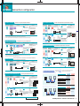
Drawing, computing, communication
A triad of high-speed response
BUS
GT15
Options
RS-232
RS-422
䡵Drawing...Equipped with a high-speed drawing chip
(GT15 only).
A beautiful and expressive screen
䡵Computing...Offers high-speed computing performance.
䡵Communication...BUS connection (GT15 only) and
RS-232 communication (max. 115.2kbps).
65536 colors
256 colors
Memory 9M
Memory 3M
Black & white,
16-step adjustment
䡵65536
Full color*1 (GT15)
䡵Black & white
16-step adjustment (GT11)
䡵Memory capacity Greatly increased
USB
Transparent
䡵Data transmission speed is up to 20
times faster than previous models.
䡵Front-mounted USB interface allows
fast data exchange.
* Functions bearing this mark are available only on GT15 series models.
All other functions are supported by both the GT11 and GT15 series.
*: Usable options vary according to the GOT being used. For details, refer to "Function list for each model" (on page 44).
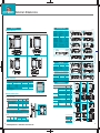
CF card
Optional expansion memory function board
High-resolution graphic board
IP67f-compliant port cover
(for replacement)
Used for project data transmissions
and for saving alarm information,
etc. All models are equipped with a
CF card interface as standard.
GT15
Memory card adaptor
Optional function board
Protection sheet
Battery
CF card → memory card (Type II)
conversion adaptor.
Installed in the GOT in
order to use optional
functions.
Protection sheet for the
screen. Affixed to the
GOT screen.
GT15: Data backup battery for clock
maintenance schedule notification data.
GT11: Data backup
battery for clock data,
alarm history, recipe
data.
Installed in the GOT for a
65,536 colors display.
Installed in GOT to permit
the use of optional functions
GT15 and to increase memory capacity.
Secured by screws at the USB interface on the GOT main unit.
Clear
4
USB interface
Standard item & front-mounted
GT11
GT15
distributed by AA ELectric 1-800-237-8274 www.a-aelectric.com
Anti-glare
(white frame)
Stand
Attachment
Used to support the GOT main unit
on a desk during debugging operations, etc.
When substituting a GOT-A900 series with a
GOT1000 series (8.4" type), the attachment is
GT15 mounted at the GOT-A900 mounting holes,
and the GOT1000 (8.4" type) is then mounted
on the attachment. Used to replace the GOTA900 serise with the GOT 1000 serise 8.4"
type.
Backlight for replacement
GT15
(Optional)
data,
GT11
(for replacement)
Backlight for TFT-color display.
GT15
5
For designers
Create highly expressive screens
that best suit your needs.
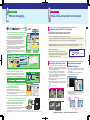
Boot logo
Unique startup screen
can be created.
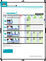
Comment groups
Up to 255 comment groups can be created
in addition to basic comments.
Images can be created in GT Designer2, and the desired
image can be displayed when GOT is started up.
Comment group 1: Line A comment
Comment group 2: Line B comment
Comment group 3: Line C comment
A company's logo and messages to the operator
can be displayed.
256-color bitmap files* can be displayed.
Features and recommended points
Efficient input of extensive
comment data by allotment.
mExample of comment group use
(1) Line-specific comment groups are created.
Line A
comment
Line B
comment
Individually
edited
Line C
comment
*: Terminal models that are unable to display 256 colors, will display in fewer colors.
Specify a desired image
using GT Designer2
When GOT is started
(2) Import
[Comment registration]
CSV / Unicode text format files can be imported.
Different files can also be input to individual
comment groups, allowing the comment input task to
be distributed among several workers, greatly
reducing the required input time.
Draw without memory capacity worries
Vastly increased
memory capacity
Standard 9MB memory on the GT15. Optional
memory expansion up to 57MB (using optional
expansion memory function board + CF card).
GOT-F900
BMP and JPEG N E W * images can be used to
create easy-to-understand screens.
Standard 3MB
GT11
x6
An assortment of fonts
allows more expression.
Supports Windows® compatible fonts*.
Standard
1MB
GT15
Optional 8MB
Standard 9MB
9 MB
x9
Optional 48MB
(3) Displayed comment group can be switched by device.
When "1" is selected
Font
Standard font
Size
6 x 8 dot
When "3" is selected
57 MB
Q64P
POWER
Line B
error
Q64P
Q25HCPU
MODE
RUN
QX42-S1
POWER
MODE
RUN
QJ61CL12
QJ61BT-11
QX42-S1
POWER
Q25HCPU
ON
RUN
QJ61CL12
QJ61BT-11
PULL
USB
QJ71C24-R2
QJ61CL12
QJ61BT-11
ERR
USER
BAT
BOOT
SW
I/O 1
POINTS 2
3
B RATE 4
5
MODE 6
7
TEST 8
PULL
QX42-S1
MODE
QJ71C24-R2
ERR
USER
BAT
BOOT
SW
I/O 1
POINTS 2
3
B RATE 4
5
MODE 6
7
TEST 8
PULL
Q64P
Q25HCPU
QJ71C24-R2
ERR
USER
BAT
BOOT
PULL
Line C
error
ON
SW
I/O 1
POINTS 2
3
B RATE 4
5
MODE 6
7
TEST 8
PULL
PULL
USB
ON
USB
Style
Gothic
12 dot
Gothic
16 dot
Gothic / Mincho
12 dot
Gothic / Mincho
16 dot
Gothic / Mincho
True type font
24 to 128 dot
Windows® font
8 to 128 dot
Gothic / Mincho
High-quality font
When "2" is selected
Line A
error
Line-specific comment groups can be created
and displayed, and switching between those
groups is possible, enabling easy integrated
control of multiple lines in a single project's data.
Language-specific comment groups can also be
created, with switching between the different
language screens.
N E W *: All True Type (other than vertical scripts)
and Open Type fonts can be displayed.
When using a Windows® font, the font style
(italics, underline, italics underline) can also be specified.
Standard fonts, high-quality fonts, and True Type
fonts can be used in Gothic or Mincho styles*.
*: Gothic and Mincho styles cannot be used together in the standard font.
Attractive characters in all sizes.
True Type fonts can be used.
The Unicode2.1 compatible standard font,
high-quality font, and True Type font, display
sharp and attractive characters in all languages.
Create elaborate, high-quality screens
that are both attractive and easy to view.
6
offered by Microsoft ® Excel.
3 MB
*: JPEG format is supported only by the GT15.
Dramatically improved display is
attractive and easy to view.
The drawing software allows easy column and line
insertions and comment No. changes similar to those
[Example of comment group use]
GOT-A900
Standard 3MB memory on the GT11.
Create screens without worrying about memory capacity.
Standard
512KB 512 KB
distributed by AA ELectric 1-800-237-8274 www.a-aelectric.com
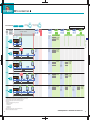
Multilingual support
Easy creation of
a multilingual screen.
To switch between Japanese, English, and Chinese screen
(1) Create the Japanese, English, and Chinese comments
in their respective columns.
Different-language comments can be created at
each comment column No., enabling switching
between Japanese, English, and Chinese screens,
etc., simply by specifying the desired column No. at
the multilingual device.
Up to 10 columns* can be created for 1 comment No.
*: For details, refer to the "Comment Group" item.
Examples of use (for switching between Japanese,
English, and Chinese)
(1) Create the Japanese, English, and Chinese
comments in their respective columns.
(2) At the multilingual device, specify the No. of the
column to be displayed.
(3) The displayed comment (language) changes.
• Language-specific alarm display screens can
also be easily created.
Column comments can be created freely for
applications, as well as for different languages.
Switch-
Switch-
ing
If D10=1,
Japanese displays
ing
If D10=2,
English displays
If D10=3,
Chinese displays
For D10
multilingual
device
(2) At the multilingual device, specify the No.
of the column to be displayed.
(3) The displayed comment (language) changes.
7
For designers
For designers
Increase design efficacy with
an impressive array of clever functions.
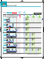
Simplified maintenance through
batch handling of recipe information.
Automated recipe operation without sequence programs
Component layering (Layer function)
Advanced recipe
䢇 Component (objects, figures) layering increases the freedom of design.
This function allows material combination data and processing conditions data, etc. (device value)
to be held at GOT, with only the required data being written/read to and from the PLC.
䢇 Display layering is possible for components such as changing numerical values and graphs,
line graphs, bar graphs, photo data, and pointers, etc.
1. Extensive amount of setting files, device points, and record points.
䢇 Offers effective use of a limited display area by allowing comments to be placed on lamps.
Photo data & pointer
Comment & lamp
䢇 A greatly expanded capacity permits up to 2048 files and 32767 device points.
Layer graphs
䢇 Up to 240 device records can be handled by a single advanced recipe setting file.
Front layer
Front layer
Features and recommended points
More freedom in screen design
2. Flexible recipe data can now be created.
䢇 Flexible recipe data can be created by combining advanced recipe settings and records.
䢇 Reading/writing is performed by specifying the recipe No. and record No., eliminating the need for a trigger device at each file.
This reduces the number of required devices, and permits trigger device concentration.*1
䢇 Up to 2048 blocks are possible, with 1 block comprising a sequential word device and random word device (1 point), and a bit device (1 point).
Back layer
Back layer
Error occurence
䢇 Because devices also permit bit and word combinations and random device settings, there is no need to concentrate
the sequential devices, thereby economizing on the number of device points.
Front layerⴐBack layer
Front layerⴐBack layer
䢇 Advanced recipe files can be edited on a personal computer.*2
Usage example
Number of device points
(max. 32767 points / setting)
Convenient handshake processing, etc.
Advanced recipe setting
Improved switch function
Advanced recipe setting 1: Curry
䢇 The order of multiple operations (word SET / bit SET, etc.)
specified by a single touch-switch can be specified as
desired. This is also convenient for handshake processing
with other devices.
Device
䢇 At ASCII display and inputs, the lower/higher bit display
order can be specified. For example, if "4142H"* is saved at
the device, the display can be specified as "AB" or "BA".
*: 41H → "A" / 42H → "B"
3. Easy handling of recipe data
at GOT
GOT
䢇 A bar-code reader can be connected to GOT, and the bytes
received as ASCII data are saved at the PLC.*
Q64P
POWER
Q25HCPU
MODE
QX42-S1
QJ71C24-R2
RUN
QJ61CL12
QJ61BT-11
ERR
USER
* The bar-code function can be used when GOT's internal RS-232 interface is not in use.
Record 2
Pork Curry
Record 3
Chicken Curry
D1000
Beef
300
0
D1001
Pork
0
300
0
0
D1002
Chicken
0
0
300
D1100
Onion
400
500
600
D1101
Potato
300
400
200
D1102
Carrot
200
250
150
䢇 Recipes can be handled easily by GOT's utility
function without having to create a recipe
operation screen.
GOT main unit
Select a recipe file
Select a record and
execute the recipe
BAT
BOOT
SW
I/O 1
POINTS 2
3
B RATE 4
5
MODE 6
7
TEST 8
PULL
PULL
USB
䢇 The order in which the read data is saved in the PLC devices
can be selected in GT Designer2 as "L/H" (lower/higher bit)
or "H/L" (higher/lower bit).
PLC
䢇 A single bar-code reader can be connected to the RS-232
interface of each GOT.
Bar-code reader
For information regarding "compatibility-confirmed" bar-code readers, refer to
the MELFANSweb website at the following address:
8
Record 1
Beef Curry
Records
(max. 240 records / setting)
Easy acquisition of external data
http://www.MitsubishiElectric.co.jp/melfansweb
Device
Comment
Max. 2048 settings / project
䢇 At ASCII inputs, up to 16 characters can be entered by a
single touch switch, permitting 16 characters, either one-byte
or two-byte character, to be entered in one operation.
Bar-code reader connection
Device blocks
(max. 2048 blocks / setting)
RS-232
distributed by AA ELectric 1-800-237-8274 www.a-aelectric.com
ON
䢇 The utility function permits the following
operations: folder create/delete, advanced
recipe file copy/delete/file name change,
record write/read/consistency check.
䢇 Advanced recipe files can be converted to
CSV files or Unicode text files.
Recipe execution
Advanced recipe
information screen
*1: The "recipe No. saving device", the "record No. saving device", and the "external control device" advanced recipe common
settings can be specified at the advanced recipe device dialog box in GT Designer2 (these settings are required when using
an advanced recipe). Recipe data reading and writing occurs in accordance with external device ON/OFF switching, and that
data displays onscreen. (It is also possible to specify a trigger device for reading/writing of each advanced recipe setting.)
*2: The advanced recipe file has a binary format. It must therefore be converted to a CSV file or Unicode text file by using GT
Designer2 or the GOT's utility. After being converted, only the device values can be edited.
Advanced recipe
record list screen
An optional function board is required.
GT15: GT15-FNB or GT15-QFNB (□M)
9
For designers
For designers
More design freedom through
flexible connectivity.
Lead the way in information sharing
between the office and worksite.
Gateway function
Improved Microcomputer connection
Be alerted to worksite errors and collect
worksite controller data from an office desk.
䢇 Expanded D-device support, with the following devices now
supported: Bit devices: L, M, SM; Word devices: R, SD.
䢇 Offers wider communication
protocol support (15 types).
Server function & client function
• Mitsubishi A/QnA/Q-computer link unit (8 types)
䢇 The number of interruption points has been increased from 1 byte
to a maximum of 4 bytes, enabling simpler control program design.
• GOT-A900 series compatibility (2 types)
䢇 The GOT1000 series has an internal clock function which can
be used for alarm displays and clock functions.*
*: GT15 requires an optional battery (GT15-BAT) in order to save clock data.
Wide PLC compatibility
Wide selection of connectable PLCs
䢇 GOT (server) can be monitored from a personal computer
(MX Component) to perform indirect reading/writing at PLC
CPU devices being monitored by GOT.
䢇 A GOT (server) can be monitored from another GOT (client)
to perform indirect reading/writing at PLC CPU devices
being monitored by GOT (server).
䢇 Even when monitoring other-brand PLC CPUs, the server
function can be used to perform reading/writing with
the MX Component*1 alone.
䢇 The client function can be used to perform indirect
reading/writing at PLC CPU brands other than the PLC
CPU brand to which GOT (client) is connected.
䢇 Communication is possible between GOT1000 and GOT-A900*2.
䢇 The GOT1000 series has expanded the range of connectable devices,
permitting connection to both Mitsubishi and other brand PLCs
(9 brands, including Omron, Yokogawa Electric, etc.).
䢇 The GT11 is equipped with high-speed RS-232 and RS-422
interfaces (standard items) which can be used in an alternating
manner, thereby enabling multiple GOTs to be connected.
(server function, client function)
(server function)
• Digital Electronics memory link format (3 types)
䢇 The GT15 is equipped with a high-speed RS-232 interface as
standard. Moreover, RS-422 communication is possible by
installing an RS-422 converter unit at the RS-232 interface.
2 Monitor other GOTs from a GOT
1 Collect data at a personal computer
• GOT-F900 series compatibility (2 types)
Features and recommended points
For wider GOT support of applications.
Worksite
Mitsubishi
PLC
Host personal
computer
(client)
Office
Bus connection
IN
Data collected
by MX Component
0 1 2 3 4 5 6 7
10 11 12 13 14 15 16 17
POWER
RUN
BATT.V
PROG.E
CPU.E
FX2N-32MR
IN
ESC
0 1 2 3 4 5 6 7
POW
10 11 12 13 14 15 16 17
RUN
ⴑ
BAT
ERR
ⴐ
LRUN
LERR
OK
Q25HCPU
RUN
STOP
POWER
Q61P-A1
FX3UC-32MT-LT
Mitsubishi PLC
QX10
QX41
POWER
MODE
RUN
ERR
USER
BAT
BOOT
PULL
USB
PULL
QX41
QJ71BR11
RUN
T.PASS
SD
ERR
QJ71BR11
MNG
D.LINK
RD
ERR
RUN
T.PASS
SD
ERR
MNG
D.LINK
RD
ERR
A62P
A4UCPU
AX10
AX10
AX10
AX10
AY11
AY11
AJ71BR11
AJ71BR11
0
1
2
3
4
5
6
7
8
9
A
B
C
D
E
F
0
1
2
3
4
5
6
7
8
9
A
B
C
D
E
F
Brand "C" PLC
GOT-A900
(client)
1
2
Brand "B" PLC
Ethernet
Brand "A" PLC
䢇 The GOT1000 series has an internal clock function that
permits alarm display and clock functions even when
connected to a PLC which has no clock.*
For connectable PLC models, see the "Connectable model list" (page 22).
For connection format specific features, see the "Connection configuration" section (page 25).
2
GOT1000
(client)
GOT1000
(Server)
Client function
Worksite
Mail transmission
function
Server function
*: GT15 requires an optional battery (GT15-BAT) in order to save clock data.
RS-422 connection
RS-232 connection
3
GOT1000
Bus connection
Mail server
Internet
Microcomputer
01
Brand "A" PLC
05
Mitsubishi PLC
Microcomputer board
Company B PLC
Company C PLC
Mail transmission function
[Gateway function compatible connection formats]
嘷: YES (compatible) ⳯: NO (not compatible)
Connection Format(Between GOT and PLC)
3 Transmit mail from GOT to a personal computer
0 1 0 1 0 1 0 1 0 1 0 0 0 0 1 1 0 1 0 1 0 1 0 1 0 1 1 0 1 0 1 0
01010101010000110101010101101010101010110101011
Company D PLC
䢇 The alarm history display function can transmit alarm
occurrence and recovery information by mail to a personal
computer or cell phone.
[Devices required for gateway function use]
• Ethernet communication unit (GT15-J71E71-100)
• Communication unit for connection to PLC
• Optional function board (GT15-FNB or GT15-QFNB (䡺M))
Mitsubishi PLC
02
10
distributed by AA ELectric 1-800-237-8274 www.a-aelectric.com
*1: Requires MX Component Version3 or later. MX Component is a communication
assistance tool that permits communications from a personal computer without having
to identify the communication protocol and module. Data logging, collection, and saving
is possible by programming at VBA. Applications that run in MX Component (MX Sheet,
etc.) can also be used.
*2: The devices required for Gateway function use at GOT1000 differ from those required
at GOT-A900. For details, see the "Gateway Function" section of the GOT-A900 Series
Operating Manual.
*3: Requires an SMTP (mail server). The mail transmission range depends on the SMTP
(mail server) specifications.
*4: Be sure to use either GT15-QBUS or GT15-QBUS2.
*5: Be sure to use either GT15-ABUS or GT15-ABUS2.
*6: Communication between the Gateway function and a PLC is possible
by using a single Ethernet communication unit.
Mitsubishi PLC/
Motion controller
or cell phone *3
䢇 Error information can be checked from a remote location
away from the worksite.
Company A PLC
• Bus connection (MELSEC-Q)*4
• Bus connection (MELSEC-QnA/A)*5
to be
(Soon
compatible)
Soon to be
(compatible)
YES/NO
嘷
嘷
• CPU direct connection
嘷
• Computer link connection
嘷
• MELSECNET/10 connection
⳯
• CC-Link connection (ID)
⳯
• CC-Link connection (via G4)
嘷
• Ethernet connection *6
嘷
Omron Corp. PLC
嘷
Sharp Corp. PLC
嘷
Toshiba Corp. PLC
嘷
Hitachi Industrial Equipment Systems Co., Ltd. PLC
嘷
Matsushita Electric Works, Ltd. PLC
嘷
Yaskawa Electric Corp. PLC
嘷
Yokogawa Electric Corp. PLC
嘷
Allen-Bradley PLC
嘷
SIEMENS PLC
嘷
Microcomputer board, personal computer, etc.
(microcomputer connection)
嘷
Servo amplifier connection
⳯
11
For designers
Create designs the way you imagined them
Reduction in screen drawing time by half*1
Reduction in
screen drawing
time by half
®
Windows standard operability
and menu
configuration
Data compatibility with
GT Designer
Use of temporary area
Equipped with a top-class
system parts library
Another screen creation tool
䢇 User libraries are also easily imported. N E W
䢇 An assortment of touch-switches and lamps, etc.,
are available to accommodate a full range of tastes,
making it easy to create a consistent design motif.
䢇 Even a novice can easily create an elegantly designed screen.
Workspace
An intuitive tree display,
with easy copying and deletion
Project workspace
Crystal
Retro
Category workspace
*: "Category" refers to objects or figures that have been grouped according to purpose.
Library workspace
Frequently used components can be registered as
"favorites", permitting quick access to an object or figure.
Property sheet
䢇 When creating screens, or
when changing a screen
layout, objects and figures can
be placed temporarily in the
"temporary area", making the
process easier.
Screen display area
(displays at GOT)
Window preview
䢇 The drawing software can display window screens (key
window, overlapping window, superimposed window) just as
they will appear at GOT, allowing them to be previewed.
䢇 The key pad can be displayed
just as it will appear at GOT,
allowing its position, size, and
appearance etc., to be checked.
Temporary area
(does not display at GOT)
AV
Soft
GOT settings can
also be specified
䢇 Settings which previously had to be specified at
the GOT, can now be specified from the
drawing software as well.
䢇 Settings such as the communication I/F
settings (number of bus connection extension
stages, etc.) and the screen-save time period,
etc., can be specified, thereby simplifying the
GOT setup procedure.
䢇 Even when using multiple GOTs, settings can be downloaded from the drawing software,
eliminating the need for individual GOT setups.
List display of object & figure setting content
Better project data maintenance efficiency
䢇 A setting content list can be displayed for the selected
object or figure.
䢇 Similar objects can be selected, and the color and font
size can be set in one go.
䢇 Multiple same-type objects and figures can be
selected, and their color and character size, etc., can
be batch-changed.
Project data consistency
check function
Dialogue box
Object & figure setting screen
䢇 A setting content screen displays by double-clicking the
object or figure.
䢇 Figure changes are immediately reflected onscreen.
This allows work to be performed while checking the
onscreen results, thereby simplifying the process and
reducing setting errors.
*: This is possible at the "Property Sheet" as well.
Library editor
Dedicated component editing screen
䢇 A component editing screen displays by double-clicking
a registered component at the library workspace.
䢇 Editing of registered components is quick and easy.
12
䢇 A "temporary area" has been
added to the editing window's
conventional screen display
area.
Editing window
GOT setup
It's easy to see the entire project so the screen to be
edited can be selected right away.
The device, color, and figure of components can be
batch-changed in screen or category units, even when
located on multiple screens.
Display of actual GOT screen
Features and recommended points
Version2
Easy creation of attractive and easy-to-view screens
Consistency
check
䢇 Consistency checks between the GOT's project
data and the personal computer project data
can be performed.
䢇 This allows project data inconsistencies to be
identified, thereby reducing unnecessary
uploads and downloads.
Reliable compatible with existing GOT projects reuse work friendly to customer
existing resources compatible
Backward compatibility
䢇 GT Designer → GT Designer2 compatibility*2
GT Designer2 is compatible with project data
created by GT Designer.
䢇 GOT-900 → GOT1000 compatibility*2
GOT1000 is compatible with project data
created at GOT-900.
*1: Compared to Mitsubishi Electric's GT Designer.
*2: Backward compatibility does not extend to certain data and functions. Moreover, GOT1000 screen data cannot be used at GOT-900.
distributed by AA ELectric 1-800-237-8274 www.a-aelectric.com
13
For designers
Operator
Efficient debugging
State-of-the-art operation environment
Drawing, computing, communication; a triad of high-speed response functions
Virtual GOT
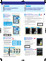
1. Debugging is possible from a single personal computer,
without actual GOT and PLC operation required.*1
A GT Simulator2 screen debugging function permits screen editing
in GT Designer2 with the results immediately verifiable in GT
Simulater2, thereby greatly reducing debugging man-hours.
The input to a touch switch is simulated by clicking on the touch
switch on GT Simulator2 with the mouse. The result of input to the
touch switch can be confirmed by a display change on GT
Simulator2, the device monitor screen on GX Simulator, or the
ladder monitor of GX Developer.
GT Simulator2 can be used in combination with a sequence program
created in GX Developer to recreate the screen motion, allowing
debugging to be performed in an intuitive manner.
System alarm and script error information can be checked in GT
Simulator2, even if no system alarm settings have been specified in
GT Designer2.
Drawing software
Virtual GOT
The GOT1000 Series offers faster response in drawing, computing,
and communication, reducing monitoring and operation stress.
[High-speed drawing] Equipped with a high-speed drawing chip (GT15 only).
Click
with mouse
Ultra high performance processing power to satisfy the most complex and demanding of applications.
Virtual PLC
Programming software
GX Simulator
GX Developer
Virtual PLC
Load program
Load drawing
data
Communication / monitoring
Programming software
GX Developer
Screen image
at personal computer
Click with mouse
2. Debugging is possible by connection with a PLC,
without actual GOT operation required
RS-232 / RS422
connection
Mitsubishi PLC
PLC ⇔ Personal Computer Connection
Mitsubishi PLC (Q/QnA/A/FX series) RS-232/RS-422
Omron Corp. PLC*2
GT Simulator 2
RS-232
RS-232
connection
Omron PLC
3. Device monitor function permits monitoring
of a wide array of devices
Monitoring is possible for displayed devices.
(GOT internal devices can also be monitored.)
High-speed RS-232 communication (max. 115.2kbps).
GOT- 900
GT15 high-speed communication is possible by bus connection.
GOT1000
Approx. 4 times faster response
For connectable PLC models, see the "Connectable model list" from page 22.
For connection format specific features, see the "Connection configuration"
section from page 25.
65536-colors full color / monochrome 16-step adjustment
Accommodates production site globalization.
Sharp display that's easy to view
Easy switching between
different languages
The standard GT15 has 256 colors. 65536 colors are available
when high-resolution graphic board is installed. JPEG N E W and
BMP images can be used at the troubleshooting screen, etc., for
vivid and easy-to-understand displays.
The GT11 is available with either a 256-colors display or a
monochrome (black & white) display. The 256-colors type
features a long-life backlight with a lifespan of 75,000 hours or
more. The monochrome (black & white) display offers a 16-step
adjustment for improved expression.
The Unicode2.1 compatible standard font, high-quality font,
and True Type font, display sharp and attractive characters
in all languages.
Allows the creation of elaborate, high-quality screens
that are both attractive and easy to view.
A high intensity, with a wide-view angle and vivid colors offers
sharp and attractive displays.
A high transmissivity protection sheet* is available to protect the
screen and prevent reflection, resulting in a clear, easy-to-view
screen.
*: The protection sheet is an optional item.
GT15
In addition to displayed devices, monitoring is also possible for
devices with common settings, as well as for overlapping windows
1 & 2, and superimposed windows 1 & 2.
One-touch switching between different-language screens*
accommodates different languages spoken by production
site operators. (GT15 only)
Because devices can be registered freely, it is possible to register multiple devices which are to be monitored.
4. Powerful support of customer specifications
compatibility checks and document creation
Response comparison with GOT-900 series
[High-speed communication]
High-speed communication is possible for connections with
both Mitsubishi and other-brand PLCs.
Sequence
program RUN
Connectable PLCs
High-speed drawing of figures and characters was realized through the development of drawing chip especially for the GOT1000 Series.
Sharp and quick drawing of complex, layered component screens, and detailed photographic data.
[High-speed computing] GT11: Equipped with 64-bit RISC processor / GT15: Equipped with 64-bit super-scalar RISC processor
GX Simulator
Debugging can be performed using a direct CPU connection between a
personal computer (GT Simulator2) and a PLC, with no actual GOT unit
operation required. Connection is possible to Mitsubishi and Omron PLCs*2.
Dramatically improved GOT total response
Features and recommended points
Version2
*: For function details, see the "Multilingual support " section on page 7.
65536 colors
256 colors
GT11
Onetouch
language
switching
While observing the operation image, the customer's screen
specifications can be arranged without actual unit operation.
Display screen snapshots can be saved to the personal
computer's hard disk as BMP/JPEG files that are extremely useful
when creating specifications and operation manuals.
STN color, 256 colors
14
*1: Requires GX Simulator (ladder logic test tool). *2: For connectable PLC model information, see the "Connectable model list" on page 24.
[Unsupported functions] Utility functions (some are usable), system monitor function, barcode function, ladder monitor function, A-list editing function, Gateway function, FA transparent function, human sensor.
STN Black & white 16-step adjustment
distributed by AA ELectric 1-800-237-8274 www.a-aelectric.com
15
Initial startup & adjustment operator
For minimizing procedure man-hours
and setup
Easy cable connection without opening the cabinet
䢇 A front USB interface allows cables to be connected without
having to open the cabinet. Work efficiency is improved by
eliminating the time-consuming process of opening and
closing the cabinet door at GOT data transmissions.
For GOT data transmissions & a variety
of external connections
High-speed downloading
/uploading* via Ethernet
Standard-item RS-232 interface
䢇 Project data from a personal computer at a remote site can be
downloaded and uploaded to a GOT terminal by way of Ethernet.
䢇 The USB interface is a standard item at all models.
Data transmission can be up to 20 times faster than the
previous RS-232 format, greatly reducing the time required
for startup and adjustment.
Download
Upload
䢇 Used for GOT data transmissions.
䢇 Used for the FA transparent function*.
GT Designer 2
Office
䢇 Equipped with an IP67 rated port cover as standard. When secured by
screws, the cover complies with the IP67f* standard.
䢇 Both the GT15 and GT11 have RS-232 interfaces located in
convenient positions (bottom, and side face, respectively)
for cable connection.
Download
Upload
*: Usable only when GT15 is BUS-connected to a Mitsubishi PLC, and when GT11 is
connected directly to a Mitsubishi PLC CPU by way of the RS-422 interface.
The RS-232 interface can be used for the following functions in addition to data transmission
: For PLC connection, for servo amplifier connection, for barcode reader connection.
*: Compliance cannot be guaranteed in all customer environments. Moreover,
the IP67 rating does not apply when a USB cable is connected.
䢇 The IP67 rated port cover is easily opened/closed by coin screws.
Ethernet
Comparison of project data downloading times
Comparison of project data downloading times
GOT-900
GOT-900
(RS-232)
GOT1000
115.2kbps Up to
(RS-232)
12Mbps Up to
(USB)
20 times faster
Short
Mitsubishi PLC
Data transmission time
Short
GT15
Long
With USB cable
Standard item IP67f
(with IP67 rated port cover installed)
FA transparent function
Comparison of project data downloading times
*1: Requires GX Developer Version 8.22Y or later.
*2: When RS-232 is used to connect GOT to the PLC, GOT can only be connected to a personal computer by the USB interface.
*3: When multiple GOT units are connected by a BUS connection, the FA transparent function can be used at each of the GOT units.
Y70
Long
GT15
GOT1000 100Mbps Up to 20 times faster
(Ethernet)
Short
Data transmission time
Long
Easy GOT data transmissions & setup
Standard-item CF card interface
䢇 All models are equipped with a CF card interface as standard.
M500
Data transmission time
38.4kbps
(RS-232)
䢇 When GOT is connected to a Mitsubishi PLC by BUS connection*3 or direct CPU connection,
program reading, writing, and monitoring can be performed via GOT.
Y100
times faster
*: Requires an Ethernet communication unit (GT15-J71E71-100) installed in a GOT main
unit where basic functions have also been installed.
*: Downloading/uploading other than the Boot OS and OS installation is possible.
(Resource data can only be uploaded.)
GOT-900
䢇 Sequence program debugging, startup, and adjustment can be performed via GOT's front USB interface.*1
There is no need to open the cabinet and change cable connections. (Operation is also possible via the RS-232 interface.)*2
M0
4
GT11
Edit sequence programs without opening the cabinet
䢇 Permits rapid GOT data transmissions even when GOT is
not connected by cable to a personal computer.
RS-422
interface
(GT11)
GT11
䢇 When using multiple GOT units, a single CF card enables
a quick GOT setup procedure simply by copying the data to
each GOT unit.
GX Developer
USB/RS-232
BUS connection
or direct CPU connection
Boot OS, OS,
project data
Transmission
Data
transmission
M0
Y100
M500
Y70
CF card
Transmission
MELSECNET/10, etc.
*: For software access ranges when using the FA transparent function, refer to manual for the software being used.
The CF card can also be used for the following GT15 functions, in addition to
data transmission: Advanced alarm, alarm history (also possible at GT11),
advanced recipe, recipe function, hard copy function, parts display function,
parts movement function.
For information regarding compatibility-confirmed CF card, refer to the
MELFANSweb website at the following address:
16
38.4kbps
(RS-232)
Worksite
38.4kbps
GOT1000
Features and recommended points
Equipped with front USB interface
Project data can be maintained
from a remote location
distributed by AA ELectric 1-800-237-8274 www.a-aelectric.com
http://www.MitsubishiElectric.co.jp/melfansweb
RS-232
interface
(GT11)
CF card
interface
(GT11)
RS-232
interface
(GT15)
CF card
interface
(GT15)
17
For maintenance personnel
Rapid diagnostics and identification
to minimize machine downtime
From error detection to recovery
The GOT1000 Series offers quick error detection and cause identification, enabling a speedy system recovery.
Alarm observation
subjects
Advanced alarm features
1. A wider monitoring range protects even
large-scale systems.
2. Rapid detection and corrective action
for a wide array of alarms.
3. Easy-to-understand error displays
for the operator.
4. Improved system alarms.
5. Support in identifying alarm causes.
Alarm observation
settings
Unit "A" observation
settings
Alarm observation
for up to
32767 devices
Alarm display settings
History file saving
Display of active and
recovery-completed alarms
Unit "B" observation
settings
Display of active
alarms only
Max. of 255
settings
3. Easy-to-understand display
䢇 The use of colors and popups produce easily recognizable alarm displays.
䢇 Ensures that alarms are not overlooked and that the alarm content is understood, resulting in a speedy system recovery.
Display subject switching
Display switching is possible to display only active alarms or to display
all content.
Popup display
Comment display color
1. A wider monitoring range protects even large-scale systems.
䢇 Alarm observation is possible for up to 32767 devices, with a maximum of 255 alarm observation setting groups.
䢇 3 types of alarm displays can be specified for a single alarm observation setting.
䢇 Up to 32767 alarms can be saved in the alarm history.
䢇 Batch display of large amounts of alarm information in large-scale systems, and unit-specific classification for easy management.
Comment display colors can be specified for each alarm status
(occurred, restored, and checked) and for each level and group, etc.
Floating alarm display
Permits the entire text of long comments which cannot
be contained in the display area to be read.
Features and recommended points
Advanced alarm
Details display
JPEG images can
be displayed in the
details display area.
Sorting
A sorting function permits the display order of the date & time, level,
group, alarm status, occurrence count, and downtime items to be
changed.
NEW
2. Rapid detection and corrective action for a wide array of alarms.
For example...
4-step alarm notification
䢇 Alarm occurrence conditions can be divided into 4
steps, and conveyed to the operator in an
easy-to-understand, step-by-step format.
1. Alarms by line (upper step)
2. Alarms by unit (middle step)
3. Alarm content (general step)
4. Troubleshooting (details step)
Alarm
occurrence
Step Alarms by line
1
(upper step)
Step
Alarms by unit
2
(middle step)
Step Alarm content
3
Step Troubleshooting
Line "A" stops
When multiple alarms occur, the above format
permits the operator to quickly organize and
identify the alarm conditions (where, what kind
of alarm), resulting in effective troubleshooting.
Where is
the error?
(general alarm)
4
(details screen)
Device "A" error
What kind
of error?
䢇 The 4 steps shown above can be freely defined to suit the
application in question, with switching between the step displays
performed by the step switching device or by touch-screen operation.
Out of material
Material
When will
recovery occur? replenishment
Cursor display color
Group-specific & level-specific displays
䢇 Alarms can be classified by group and level, with only the
specified alarms being displayed.
䢇 This makes it easy to identify the locations and types of alarms, even
when many alarms have occurred, and permits the higher priority
alarms to be handled first, resulting in a speedy system recovery.
18
Alarm
Group
Level
M0
M1
M2
M3
M4
M5
M6
M7
M8
M9
Transport G
Transport G
Transport G
Transport G
Transport G
Process G
Process G
Process G
Process G
Process G
Mid-level
Mid-level
Mid-level
Mid-level
Major
Major
Minor
Minor
Minor
Minor
Group
Transport G alarm display
Transport G major alarms display
1. By group
Alarms are divided into groups (transport unit group,
processing unit group, etc.), with alarms displaying
only for the specified groups.
2. By level
Alarms are divided into levels (major, mid-level, minor),
with only the specified level alarms displaying.
3. Combination group & level
Only the specified group and level alarms display.
A popup display format ensures that user alarms and system
alarms are not missed. The background color can be specified.
4. Improved system alarms
䢇 The PLC/GOT/Network monitoring subject can be specified in advance, with only those specified alarms being displayed.
䢇 If desired, only the active alarms are displayed. An alarm history display and history file saving are also possible.
5. Support in identifying alarm causes (utility function)
Combination
level
& group
Level
The cursor display color can be specified. Alarm displays are harder
to miss, and the freedom of screen design has been increased.
Alarm popup display
Minor alarm display
distributed by AA ELectric 1-800-237-8274 www.a-aelectric.com
䢇 Alarm occurrence conditions can be displayed in time-series graph form.
䢇 Alarm occurrence counts can be displayed in bar-graph form.
䢇 A graphical statistics display facilitates efficient analysis of error causes.
19
For maintenance personnel
For maintenance personnel
A more intuitive representation of
error conditions
For instantaneous checks and changes from
GOT even without a dedicated system
Convenient consumable
item maintenance
䡵Maintenance schedule notification function (GT15 only)
Sequence program monitoring & troubleshooting
1st notification
System
alarm
occurs
1. Color-coded front face LED
䢇 The color of the LED on the front of the GOT unit
indicates whether the backlight is OFF or has expired.
[POWER LED: Color-coded message]
Green ON
When normal power is being supplied
Orange ON
When in screen-save mode
Orange/green blinking
When backlight life has expired
OFF
When power is not being supplied
Ladder monitor function (MELSEC affinity)
Backlight maintenance required soon.
䢇 Mitsubishi PLC sequence program monitoring, device searches, and troubleshooting can be performed.
[Ladder monitor] Sequence program ladder format monitoring.
Statements, notes, and device comments (max. 32 chars.) specified at GX Developer can be displayed.
[Trouble shooting] When a problem occurs, a back-tracking ladder search can be performed to find the contact that is causing the coil
ON (or OFF) condition.
[Touch search*1] A displayed coil (or contact) can be touched to facilitate a search of that device's contacts (or coils).
[Search] Device, contact, coil, step, and ladder END searches are possible.
[Test] Device values and timer (T) / counter (C) setting values can be changed.
[Ladder HOLD*1] An internal flash memory or standard CF card ladder HOLD can
Requires optional function board.
be performed.
GT15...GT15-FNB or GT15-QFNB (䡺M)
*1: MELSEC-Q/QnA series only.
䢇 Use together with the alarm history function to easily identify alarm causes.
2. Maintenance schedule notification
function (GT15 only)
Features and recommended points
Color-coded front face LED &
maintenance schedule notification function
The GT15-QFNB (䡺M) is required when using
the Q/QnA ladder monitor function.
2nd notification
䢇 The backlight lifespan can be monitored by an automatic
"power ON time" count function, combined with a 2-stage
maintenance schedule notification function.
Ladder monitor
Device search
Trouble shooting
System
alarm
occurs
䢇 Monitored subjects
• Backlight, display area (power ON time)
• Touch-keys (key pressing count)
• Internal flash memory (writings count)
䢇 Facilitates scheduled maintenance, thereby preventing
system malfunctions.
Requires optional function board.
GT15...GT15-FNB or GT15-QFNB (䡺M)
Battery required.
GT15...GT15-BAT
Backlight maintenance required.
Easy monitoring of servo amplifier parameter settings, etc.
A-list editing function (MELSEC affinity)
Servo amplifier connection
Convenient method for minor
program changes onsite
䢇 GOT can be connected to a servo amplifier to perform the
following operations: parameter monitoring & setting,
alarm displays (current alarms / alarm history), status
data display, external inputs/outputs prohibit or enable,
servo requests (primarily, data clear, prohibit, and cancel
requests), station No. setting (direct station No. setting /
indirect station No. setting / all stations setting).*
䡵Connectable servo amplifiers
MR-J2S-䡺A
MELSERVO-J2-super series
MR-J2S-䡺CP
MR-J2M-P8A
MELSERVO-J2M series
MR-J2M-䡺DU
*: GOT cannot be connected simultaneously to both a servo amplifier and a PLC.
Requires optional function board.
GT15...GT15-FNB or GT15-QFNB (䡺M)
GT11...GT11-50FNB
䢇 The parameter setting screen and alarm screen can be freely created by the user.
With 1 servo amplifier
GOT
Servo
amplifier
With multiple servo amplifiers
GOT
OPEN
Servo
amplifier
OPEN
Servo
amplifier
OPEN
System monitor function (MELSEC affinity)
OPEN
C
N
1
A
C
N
1
B
C
N
1
A
C
N
1
B
C
N
3
C
N
2
E
N
C
C
N
3
C
N
2
E
N
C
C
N
3
L3
U
V
W
Cable (MR-CPCATCBL3M (3m)) can be fabricated by the user.
1st axis
(St. 0)
RS-422
cable
L1
L2
L3
U
V
W
2nd axis
(St. 1)
RS-422
cable
Cable fabricated by user
distributed by AA ELectric 1-800-237-8274 www.a-aelectric.com
)
L2
)
)
)
L1
(
C
N
1
B
C
N
2
E
N
C
(
C
N
1
A
C
N
3
(
C
N
1
B
C
N
2
E
N
C
Servo motor
20
Servo
amplifier
C
N
1
A
(
RS-232
䢇 MELSEC-A series PLC sequence programs can be edited
in a list format (instruction word).
䢇 Same key configuration as the A8UPU.
䢇 Permits minor program changes onsite, even without peripheral devices.
䢇 The GT15 permits sequence program editing while viewing
the ladder (combined with the ladder monitor function).
L1
L2
L3
U
V
W
32nd axis
(St. 31)
L1
L2
L3
U
V
W
RS-422
cable
*: RS-422 converter unit
(GT15-RS2T4-9P) is required for GT15.
Sequence device monitoring / changes
䢇 Mitsubishi PLC CPU devices can be monitored and changed.
• Monitoring can be performed by selecting the device to be monitored,
or by specifying the initial device.
• The timer (T) / counter (C) current values and setting values can be changed.
䢇 A special function unit's buffer memory (BM) can be monitored and changed.
䢇 The display format (decimal / hexadecimal) and the device comment display
status (ON/OFF) can be switched.
21
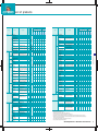
Connectable model list
The GOT1000 series allows connection to Mitsubishi PLCs and a variety of other FA devices.
[PLC/motion controller]
Mitsubishi PLCs/motion controllers
Series
Model
name
Connection configuration
BUS CPU Computer- MELSEC CC-Link CC-Link Ethernet
(ID) (via G4)
connection direct link con- NET/10
*1
*4
*1*3
*1*4
*1*2 connection nection *5
嘷 *7
嘷
⳯
⳯
⳯
嘷
嘷
嘷
嘷
嘷
嘷
*9
嘷
*11
嘷
⳯
嘷
嘷
嘷
*8*10
⳯
嘷
嘷
⳯
嘷
嘷
⳯
嘷
⳯
嘷
*10
⳯
MELSECA series
嘷
嘷
嘷*12
嘷
嘷
嘷
嘷
⳯
嘷
Motion
controller
CPU
(Q series)
嘷
嘷
嘷
嘷
嘷
嘷
⳯
嘷
嘷
*14
Model
name
A2USCPU
MELSECA2USCPU-S1
A series
(AnSCPU type) A2USHCPU-S1
*8
*1: Supported only by the GT15.
*2: When connecting multiple GOTs, note that the following GOT models cannot be used together:
GOT1000 series, GOT-A900 series, GOT800 series, and A77GOT.
*3: When MELSEC/H is used in NET10 Mode, the GOT terminal cannot be connected directly to a
Remote I/O station.
*4: CC-Link (ID): Connected as CC-Link (intelligent device station). CC-Link (via G4): Connected to a
CC-Link system via AJ65BT-G4-S3.
*5: When using A Series computer link (C24 modules) with QCPU/QnACPU, only the device ranges
within QnACPU specifications are supported.
The following devices cannot be monitored:
· Devices that have been newly added to the QCPU/QnACPU.
· Latch relay (L) and step relay (S).
In the QCPU/QnACPU, the latch relay (L) and step relay (S) are separate devices from the
internal relay (M), but the internal relay is nonetheless accessed when either the latch relay or
step relay is specified.
· File register (R)
· Local devices
*6: Use CPU function version "B" or later in a multiple CPU system.
*7: When using a BUS extension connector box, it must be installed at an extension base. (It cannot
be installed at the main base.)
*8: Use function version "B" or later for the CPU and MELSECNET/H network unit.
*9: Does not support automatic system switch. (If there is only 1 GOT, plug the GOT cable into the
CPU of the control system to be monitored. If there are 2 GOTs, plug each of them into the
respective CPUs of the "A" and "B" systems to be monitored.)
*10: Does not support automatic system switch. (Use the script to switch systems.)
*11: With redundant system, the standby system automatically takes over the control if control
system goes down.
*12: In Q4ARCPU redundant systems, GOT must be BUS-connected to the last stage's redundant
system extension base A68RB version "B" or later.
*13: Computer link unit software version "U" or later must be used for the A2SCPU, A2SHCPU,
22
Series
Motion
controller
CPU
(A series)
(large type)
Motion
controller
CPU
(A series)
(small type)
MELSECFX series
A1SCPU
A1SCPUC24-R2
A1SHCPU
A2SCPU
A2SCPU-S1
A2SHCPU
A2SHCPU-S1
A1SJCPU
A1SJCPU-S3
A1SJHCPU
A0J2HCPU
A0J2HCPUP21
A0J2HCPUR21
A0J2HCPU-DC24
A2CCPU
A2CCPUP21
A2CCPUR21
A2CCPUC24
A2CCPUC24-PRF
A2CJCPU-S3
A1FXCPU
Q172CPU *16
Q173CPU *16
Q172CPUN *16
Q173CPUN *16
Q172HCPU
Q173HCPU
A273UCPU
A273UHCPU
A273UHCPU-S3
A373UCPU
A373UCPU-S3
A171SCPU
A171SCPU-S3
A171SCPU-S3N
A171SHCPU
A171SHCPUN
A172SHCPU
A172SHCPUN
A173UHCPU
A173UHCPU-S1
FX0S
FX0N
FX1S
FX1N
FX1NC
FX2N
FX2NC
FX3UC
䡵Modules that can be connected with Mitsubishi PLC
Connection configuration
BUS CPU Computer- MELSEC CC-Link CC-Link Ethernet
(ID) (via G4)
connection direct link con- NET/10
*1
*4
*1*3
*1*4
*1*2 connection nection *5
䢇For computer link connection
Computer link modules/serial communication modules *1
Model
CH1
CH2
CPU series
嘷
MELSEC-Q series (Q mode)
MELSECNET/H remote I/O stations
嘷
嘷
*13*14
嘷
嘷
嘷
⳯
嘷
嘷
MELSEC-Q series (A mode)
MELSEC-QnA series
嘷
*15
嘷
⳯
嘷
*13*14
嘷
⳯
嘷
⳯
嘷
嘷*14
嘷
嘷
⳯
⳯
嘷
嘷
⳯
⳯
⳯
⳯
⳯
⳯
嘷
嘷
⳯
⳯
⳯
⳯
⳯
⳯
⳯
⳯
⳯
⳯
嘷
嘷
嘷
嘷
嘷
嘷
嘷
*18
*18
*19
*19
*19
*19
*19
嘷
嘷
嘷
嘷
嘷
⳯
⳯
⳯
⳯
嘷
嘷
嘷
*17
嘷
嘷
嘷
嘷
嘷
⳯
嘷
嘷
嘷
嘷
嘷
嘷
嘷
*20
*13
⳯
MELSEC-A series
A series Motion controller CPU
QJ71C24
QJ71C24-R2
QJ71C24N
QJ71C24N-R2
QJ71C24N-R4
QJ71CMO
A1SJ71UC24-R2
A1SJ71UC24-R4
AJ71QC24
AJ71QC24-R2
AJ71QC24-R4
AJ71QC24N
AJ71QC24N-R2
AJ71QC24N-R4
A1SJ71QC24
A1SJ71QC24-R2
A1SJ71QC24N
A1SJ71QC24N-R2
AJ71UC24
AJ71UC24
A1SJ71UC24-R2
A1SJ71UC24-R4
A1SJ71C24-R2
A1SJ71C24-R4
A1SCPUC24-R2
A2CCPUC24
*1: RS-485 communication is not possible; therefore, A0J2-C214-S1 is
not available.
When using A Series computer link (C24 modules) with
QCPU/QnACPU, only the device ranges within QnACPU
specifications are supported.
The following devices cannot be monitored:
· Devices that have been newly added to the QCPU/QnACPU.
· Latch relay (L) and step relay (S).
In the QCPU/QnACPU, the latch relay (L) and step relay (S) are
separate devices from the internal relay (M), but the internal relay is
nonetheless accessed when either the latch relay or step relay is
specified.
*2
*2
*3
*4
*4
*4
*4
*4
*4
*4
*4
*4
*4
*4 *6
*4 *5
*5
*5
*5
*5 *6
*5 *6
*4
RS-232
RS-232
RS-232
RS-232
RS-422/485
Module connector
RS-232
RS-422/485
RS-232
RS-232
RS-422
RS-232
RS-232
RS-422
RS-232
RS-232
RS-232
RS-232
RS-232
RS-232
RS-232
RS-422/485
RS-232
RS-422/485
RS-232
RS-232
· File register (R)
· Local devices
*2: With function version "A", CH1 or CH2 can be connected. With
function version "B" or later, both CH1 and CH2 can be connected.
*3: Only CH2 can be connected.
*4: Either CH1 or CH2 can be connected.
*5:: When connecting to A1SHCPU, A2SCPU(S1), A2SHCPU(S1),
A1SJHCPU, A0J2HCPU, A171SHCPU(N), A172SHCPU(N), use
computer link module software version U or later version.
*6: Computer link module/serial communication module operate within
the range of devices available on AnACPU. (R device cannot be
used.)
䢇For MELSECNET/10 connection
CPU series
MELSEC-Q series (Q mode)*1
MELSEC-QnA series
⳯
嘷
⳯
⳯
⳯
⳯
⳯
A1SHCPU, A1SJHCPU, A0J2HCPU, A171SHCPU, and A172SHCPU computer link
connections.
The A0J2-C214-S1, dedicated computer link unit for A0J2HCPU, cannot be used.
*14: Only the following software version or later can be used to monitor the AnNCPU (S1), A2SCPU,
A0J2HCPU, and A2CCPU. Earlier versions cannot be used.
· AnNCPU (S1)
: A "with link" status requires version "L" or later, and a
"without link" status requires version "H" or later.
· A2SCPU
: Version "H" or later
· A0J2HCPU (with link/without link) : Version "E" or later
· A0J2HCPU-DC24
: Version "B" or later
· A2CCPU
: Version "H" or later
*15: Cannot connect to BUS if an extension base is connected.
*16: Use of the SV13, SV22, or V43 requires a motion controller with the following OS version
installed.
SW6RN-SV13Q□: 00H or later (00E or later when Q172CPU, Q173CPU and BUS connection,
or direct CPU connection exists)
SW6RN-SV22Q□: 00H or later (00E or later when Q172CPU, Q173CPU and BUS connection,
or direct CPU connection exists)
SW6RN-SV43Q□: 00B or later
*17: Only a USB interface is available on Q172HCPU and Q173HCPU units.
The Q172HCPU and Q173HCPU can be accessed using a multi-CPU system QCPU RS-232.
*18: Use a unit with the following serial No.
Q172CPU Serial No. K******* or later
Q173CPU Serial No. J******* or later
*19: Use a unit with the following serial No.
Q172CPU Serial No. N******* or later
Q173CPU Serial No. M******* or later
*20: If an extension base is to be used, use the A168B.
MELSEC-Q series (A mode)
MELSEC-A series
A series Motion controller CPU
䢇For Ethernet connection
MELSECNET/H / MELSECNET/10 modules
Optical loop
Coaxial BUS
QJ71LP21
QJ71LP21-25
QJ71LP21S-25
AJ71QLP21
AJ71QLP21S
A1SJ71QLP21
A1SJ71QLP21S
AJ71LP21
A1SJ71LP21
AJ71QBR11
A1SJ71QBR11
MELSEC-QnA series
MELSEC-Q series (A mode)
MELSEC-A series
A series Motion controller CPU
CC-Link unit
QJ61BT11
QJ61BT11N
AJ61QBT11
A1SJ61QBT11
AJ61BT11
A1SJ61BT11
MELSEC-QnA series
AJ71BR11
A1SJ71BR11
䢇For CC-Link (ID) connection *1
CPU series
CPU series
MELSEC-Q series (Q mode)
QJ71BR11
*1: Use function version "B" or later for the CPU and MELSECNET/H network unit.
MELSEC-Q series (Q mode)
RS-422/485
RS-232
RS-422/485
RS-232
RS-422/485
RS-232
ⴑ
ⴑ
RS-422/485
RS-232
RS-422/485
RS-422/485
RS-232
RS-422/485
RS-422/485
RS-232
RS-422/485
RS-232
RS-422/485
RS-422/485
ⴑ
ⴑ
ⴑ
ⴑ
ⴑ
RS-422/485
Connectable model list
Q00JCPU
*6
Q00CPU
*6
Q01CPU
*6
Q02CPU
*6
Q02HCPU
*6
Q06HCPU
*6
Q12HCPU
Q25HCPU
Q12PHCPU
Q25PHCPU
Q12PRHCPU
Q25PRHCPU
MELSECNET/H QJ72LP25-25
remote I/O QJ72LP25G
QJ72BR15
stations
Q02CPU-A
MELSEC-Q
Q02HCPU-A
series
Q06HCPU-A
(A mode)
Q2ACPU
MELSECQ2ACPU-S1
QnA series
(QnACPU type) Q3ACPU
Q4ACPU
Q4ARCPU
Q2ASCPU
MELSECQ2ASCPU-S1
QnA series
(QnASCPU type) Q2ASHCPU
Q2ASHCPU-S1
A2UCPU
MELSECA2UCPU-S1
A series
(AnCPU type) A3UCPU
A4UCPU
A2ACPU
A2ACPUP21
A2ACPUR21
A2ACPU-S1
A2ACPUP21-S1
A2ACPUR21-S1
A3ACPU
A3ACPUP21
A3ACPUR21
A1NCPU
A1NCPUP21
A1NCPUR21
A2NCPU
A2NCPUP21
A2NCPUR21
A2NCPU-S1
A2NCPUP21-S1
A2NCPUR21-S1
A3NCPU
A3NCPUP21
A3NCPUR21
MELSEC-Q
series
(Q mode)
In addition to a BUS connection, GT15 can also be connected to a MELSECNET/10 or Ethernet network.
The GT11 is equipped with RS-232 and RS-422 interfaces (as standard) which can be used in an alternating manner, thereby enabling multiple GOTs to be connected.
*2
*2
*2
*2
*1: This is a "Ver.1 intelligent device station" permitting monitoring by transient and cyclic
communication. Cyclic communication restrictions exist, however, in the remote net Ver.2
mode, and in the remote net added mode. For details, refer to the user's manual for the CCLink master/local unit being used.
*2: GOT can perform transient communication only with CC-Link units running function version "B"
and software version "J" or later.
MELSEC-Q series (A mode)
MELSEC-A series
A series Motion controller CPU
Ethernet module *1
QJ71E71-100
QJ71E71-B5
QJ71E71-B2
QJ71E71
AJ71QE71N3-T
AJ71QE71N-B5
AJ71QE71N-B2
AJ71QE71N-T
AJ71QE71N-B5T
AJ71QE71
AJ71QE71-B5
AJ71E71N3-T
AJ71E71N-B5
AJ71E71N-B2
AJ71E71N-T
AJ71E71N-B5T
AJ71E71-S3
A1SJ71QE71N3-T
A1SJ71QE71N-B5
A1SJ71QE71N-B2
A1SJ71QE71N-T
A1SJ71QE71N-B5T
A1SJ71QE71-B5
A1SJ71QE71-B2
A1SJ71E71N3-T
A1SJ71E71N-B5
A1SJ71E71N-B2
A1SJ71E71N-T
A1SJ71E71N-B5T
A1SJ71E71-B5-S3
A1SJ71E71-B2-S3
*1: When using an A-series Ethernet (E71 modules) with QCPU/QnACPU, only the device ranges
within AnACPU specifications are supported except for the following devices.
· Devices that have been newly added to the QCPU/QnACPU.
· Latch relay (L) and step relay (S).
(At the QCPU/QnACPU, the latch relay (L) and step relay (S) are separate devices from the
internal relay (M), but the internal relay is nonetheless accessed when either the latch relay or
step relay is specified.)
· File register (R)
· Local devices
䢇For CC- Link (via G4) connection *1
CPU series
MELSEC-Q series (Q mode)
CC-Link unit
QJ61BT11
QJ61BT11N
Peripheral device
connection unit
AJ65BT-G4-S3
*1: The GT11 can monitor only the master station.
distributed by AA ELectric 1-800-237-8274 www.a-aelectric.com
23
Connection configuration
Connectable model list
To achieve optimum performance, take into consideration: connection specifications (example QBUS
vs. Serial RS232), the distance requirements (distance to first terminals connection, total overall
distance and distance between terminals) and number of GOT terminals required.
Achieve maximum 115kbps high-speed communication with other manufacturers' PLCs via RS-232 communication.
Having an RS-422 converter mounted, the standard RS-232 interface on the GT15 can be used as RS-422 interface.
The GT11 model is embedded with both an RS-232 and RS-422 interface as standard.
Other manufacturers' PLCs/motion controllers
Manufacturer
OMRON
Model name
Micro PLC
Small-sized
PLC
SHARP
TOSHIBA
PROSEC
T series
V series
Hitachi
Industrial
Equipment
Systems
Large-sized
H series
H200 to 252
series
H series
board type
EH-150 series
RS-422 RS-232 RS-422 RS-232
ⴒ
ⴒ
䡬
䡬
ⴒ
䡬
䡬
ⴒ
ⴒ
䡬
䡬
ⴒ
ⴒ
䡬
䡬 *1
ⴒ
ⴒ
ⴒ
ⴒ
䡬
䡬
䡬 *1
ⴒ
䡬 *1
ⴒ
ⴒ
ⴒ
ⴒ
ⴒ
ⴒ
ⴒ
ⴒ
ⴒ
ⴒ
ⴒ
䡬
䡬
䡬
䡬 *1
䡬 *1
䡬 *1
ⴒ
ⴒ
ⴒ
ⴒ
ⴒ
䡬
䡬
ⴒ
䡬 *1
ⴒ
ⴒ
ⴒ
䡬
䡬
ⴒ
䡬
ⴒ
䡵Modules that can be connected to other manufacturer's computer link module
Manufacturer
OMRON
Upper-level link unit,
communication unit,
communication board
SHARP
Link unit
RS-422
C200H-LK202-V1
C500H-LK201-V1
CQM1-SCB41
CJ1W-SCU41
CS1W-SCB41
C200HW-COM03
C200HW-COM06
JW-21CM
JW-10CM
Model name
FP0-C16CT
FP0-C32CT
FP1-C24C
FP1-C40C
FP2
FP2SH
FP3
FP5
FP10 (S)
FP10SH
FP-M (C20TC)
FP-M (C32TC)
Yaskawa Electric
GL120
GL130
GL60S
GL60H
GL70H
CP-9200SH
CP-9300MS
MP-920/930
MP-940
PROGIC-8
CP-9200 (H)
Yokogawa
FA500
FA500
Electric
FA-M3
F3SP05
F3SP08
F3SP10
F3SP20
F3SP30
F3FP36
F3SP21
F3SP25
F3SP35
F3SP28
F3SP38
F3SP53
F3SP58
F3SP59
Allen-Bradley SLC 500 series *2
SLC500-20
(Rockwell)
SLC500-30
SLC500-40
SLC5/01
SLC5/02
SLC5/03
SLC5/04
SLC5/05
MicroLogix 1000 series 1761-L10BWA
(Digital CPU) *2
1761-L10BWB
1761-L16AWA
1761-L16BWA
1761-L16BWB
1761-L16BBB
1761-L32AWA
1761-L32BWA
1761-L32BWB
1761-L32BBB
1761-L32AAA
MicroLogix 1000 series 1761-L20AWA-5A
(Analogue CPU) *2*3*4 1761-L20BWA-5A
1761-L20BWB-5A
MicroLogix 1200 series *2 1762-L24BWA
2
MicroLogix 1500 series * 1764-LSP
SIEMENS
SIMATIC S7-300 series
SIMATIC S7-400 series
C200HW-COM06
CQM1-CIF01
CQM1-CIF02
CQM1-SCB41
CPM1-CIF01
CPM2C-CN111
CPM2C-CIF01-V1
ZW-10CM
Computer link connection CPU direct connection
RS-422 RS-232 RS-422 RS-232
Matsushita Electric Works
ⴒ
ⴒ
䡬
ⴒ
Series
MELSERVOJ2-super series
Model
MR-J2S-䡺A
MR-J2S-䡺CP
䢇QCPU (Q mode) / Q series Motion controller CPU
Connection configuration Communication interface
installed on GOT side
ⴒ
ⴒ
ⴒ
䡬
ⴒ
䡬
䡬
ⴒ
GT15-75QBUSL*2
GT15-75QBUS2L*2
GT15-QBUS *2*4
GT15-QBUS2 *2*4
GT15
ⴒ
ⴒ
ⴒ
ⴒ
䡬 *1
䡬
䡬
ⴒ
ⴒ
ⴒ
䡬
䡬
䡬
Series
MELSERVOJ2M series
GT15-QC䡺B
Bus
connection GT15-QC䡺BS
cable
Bus connection unit
GT15-75ABUSL*3
GT15-75ABUS2L*3
GT15-ABUS *3*4
GT15-ABUS2 *3*4
GT15
GT15-C䡺NB
Bus
connection GT15-AC䡺B
GT15-A1SC䡺B
cable
GT15-C䡺EXSS-1*1
GT15-C䡺BS
GT15-J2C䡺B
ⴒ
3 units
GT15-A1SC䡺NB
Bus connection unit
GT15-75ABUSL*3
GT15-75ABUS2L*3
GT15-ABUS *3*4
GT15-ABUS2 *3*4
GT15
ⴒ
ⴒ
QnA / ACPU
)
when connected with
QnACPU type/AnCPU type
when connected with
QnASCPU type/AnSCPU type
䢇A series Motion controller CPU
ⴒ
䡬
(
2 units AnN,(AnSH),A1SJ(H)
1 unit A0J2HCPU
Maximum connection distance
36.6m
䡬
GT15-C䡺NB
Bus
connection GT15-AC䡺B
GT15-A370C䡺B-S1
cable
GT15-A370C䡺B
GT15-A1SC䡺B
GT15-C䡺EXSS-1*1
GT15-C䡺BS
䡬
Maximum number of GOTs connected
3 units
CPU direct connection
(
2 units A171SHCPUN
A172SHCPUN
A series Motion Controller CPU
)
Maximum connection distance
36.6m
when connected with A273UCPU/A273UHCPU(-S3)
/A373UCPU(-S3): with extension base
32.5m
when connected with A273UCPU/A273UHCPU(-S3)
/A373UCPU(-S3): without extension base
33m
when connected with A171SHCPUN/A172SHCPUN/
A173UHCPU(-S1): with extension base
30m
when connected with A171SHCPUN/A172SHCPUN/
A173UHCPU(-S1): without extension base
*1: See the external dimensions information (page 42 and following) for the GT15-C䡺EXSS-1 cable shape.
*2: Use of the Gateway function requires the GT15-QBUS (2). Note that the GT15-75QBUS (2) L cannot be used.
*3: Use of the Gateway function requires the GT15-ABUS (2). Note that the GT15-75ABUS (2) L cannot be used.
*4: Available soon.
Refer to Bus connection on page 30 and following for details.
MELSEC-Q/QnA/A/FX series can be connected via CPU direct connection at the lowest cost.
䢇QCPU / Q series Motion controller CPU
ⴒ
ⴒ
䡬
ⴒ
Connection configuration
RS232
ⴒ
ⴒ
GT15
JAMSC-120NOM27100 CP-217IF
JAMSC-IF612
LC02-0N
F3LC11-2N
F3LC11-1N
F3LC11-1F
F3LC12-1F
RS-232
cable
GT01-C䡺R2-6P
䡬
GT15-RS2T4-9P
RS422
GT11
RS-422
cable
RS-232/422
conversion cable
GT01-C䡺R4-25P
FA-CNV䡺CBL*5
30: 3m
100: 10m
200: 20m
300: 30m
2402: 0.2m
2405: 0.5m
Maximum number of GOTs connected
1 unit
QCPU
Q series Motion Controller CPU
(CPU port: RS-232)
0
1
2
3
4
5
6
7
8
9
A
B
C
D
E
F
QCPU
Q series Motion Controller CPU
(CPU port: RS-232)
Maximum connection distance
30.5m
Embedded
in GOT
Connected to
0
1
2
3
4
5
6
7
8
9
A
B
C
D
E
F
䢇QnA / ACPU / A series Motion controller CPU
RS-422 converter
GT15-RS2T4-9P
RS-422 GT01-C䡺R4-25P
30: 3m
cable 100: 10m
Maximum number of GOTs connected
1 unit
200: 20m
300: 30m
QnA / ACPU /
A series Motion Controller CPU
(CPU port: RS-422)
Maximum connection distance
RS-422
䡬
1 unit
30: 3m
RS422
RS-232
Maximum number of GOTs connected
Maximum connection distance
RS-422 converter
GT15
AFP5462
CP-217IF
Embedded
in GOT
Connection cable
3m
COMM-H
COMM-2H
AFP2462
AFP3462
JAMSC-IF60
JAMSC-IF61
LC01-0N
LC02-0N
F3LC01-1N
Communication interface
installed on GOT side
GT11
䡬
ⴒ
RS-232
COMM-H
COMM-2H
Model
MR-J2M-P8A
MR-J2M-䡺DU
0
1
2
3
4
5
6
7
8
9
A
B
C
D
E
F
Maximum number of GOTs connected
36m
ⴒ
QCPU (Q mode)
Q series Motion Controller CPU
37m
ⴒ
䡬
Connected to
Maximum connection distance
䡬
Sets and displays parameter when connected to the GOT.
RS-422
Maximum number of GOTs connected
䢇QnA / ACPU
GT15
RS-232
Connection cable
䡬
ⴒ
䡬
䡬
ⴒ
[Servo amplifiers]
Mitsubishi servo amplifiers
Touch switches achieves as quick response as pushbuttons.
Bus connection unit
䡬
ⴒ
RS-422
Hitachi Industrial Equipment Systems
Intelligent serial port module
Matsushita Electric Works
Computer communication unit
Yaskawa Electric
Memo BUS module
Yokogawa Electric
Personal computer link module
Bus connection
5 units
*1: RS-422 or RS-232 is selectable.
*2: Connection to DH485 network possible via adaptor (1770-KF3).
*3: Connection to DH485 requires a "Series-C" or later CPU. ("Series-B" and earlier models do not support
the DH485 protocol.)
*4: A one-to-one connection requires a "Series-D" or later CPU. ("Series-C" and earlier models do not
support the DF1 half-duplex format.)
Manufacturer
RS-232
C200H-LK201-V1
C500H-LK201-V1
CS1W-SCU21
CS1W-SCB21
CS1W-SCB41
CJ1W-SCU41
C200HW-COM02
C200HW-COM05
Manufacturer
Connection configuration
Large-sized
PLC
CPM1A
CPM1
CPM2A
CPM2C
C200H
C200HS
C200HX
C200HG
C200HE
CQM1
CQM1H
CS1H
CS1J
CS1D
CJ1H
CJ1G
CJ1M
C1000H
C2000H
CV500
CV1000
CV2000
CVM1
JW-21CU
JW-31CUH
JW-50CUH
JW-22CU
JW-32CUH
JW-33CUH
JW-70CUH
JW-100CUH
JW-100CU
Z-512J
T2 (PU224)
T2E
T2N
T3
T3H
model 3000 (S3)
model 2000 (S2)
H-302 (CPU2-03H)
H-702 (CPU2-07H)
H-1002 (CPU2-10H)
H-2002 (CPU2-20H)
H-4010 (CPU3-40H)
H-300 (CPU-03Ha)
H-700 (CPU-07Ha)
H-2000 (CPU-20Ha)
H-200 (CPU-02H, CPE-02H)
H-250 (CPU21-02H)
H-252 (CPU22-02H)
H-252B (CPU22-02HB)
H-252C (CPU22-02HC)
H-252C (CPE22-02HC)
H-20DR
H-28DR
H-40DR
H-64DR
H-20DT
H-28DT
H-40DT
H-64DT
HL-40DR
HL-64DR
EH-CPU104
EH-CPU208
EH-CPU308
EH-CPU316
Computer link connection CPU direct connection
Connectable model list
[PLC/motion controller]
GT11
Embedded
in GOT
30m
*5: This item is developed by Mitsubishi Electric Engineering Company Limited and sold through your local sales office.
24
distributed by AA ELectric 1-800-237-8274 www.a-aelectric.com
25
Connection configuration
䢇FX series (FX3UC)
GT15
Embedded
in GOT
RS-232 GT01-C䡺R2-9S
30 : 3m
cable
FX series (FX3UC)
when using the function extension
board or the special adaptor
specified on the right.
3
units
(
when using RS-422 CPU port )
(Function extension board (FX3U-232-BD) for RS-232)
(Special adaptor (FX3U-232-ADP) for RS-232)*4
2 units
RS232
Computer link connection
Maximum number of GOTs connected
ESC
POW
RUN
ⳮ
BAT
ERR
Ⳮ
LRUN
䢇QCPU (Q mode) / QnACPU / Q series Motion controller CPU
Connection configuration Communication interface
installed on GOT side
Maximum number of GOTs connected
connection cable
1 unit
LERR
OK
Maximum connection distance
GT11
3m
GT15-RS2T4-9P
cable
RS422
Maximum number of GOTs connected
10 : 1m
30 : 3m
100 : 10m
200 : 20m
300 : 30m
2 units
when using the CPU port and
the function extension board
specified on the right.
( 3 units when using RS-232 special adaptor)
Embedded
in GOT
RS232
RS-232 To be fabricated by user.
cable D-sub 9 pins
ESC
POW
RUN
ⳮ
BAT
Ⳮ
Maximum connection distance
(female)
RUN
STOP
Maximum number of GOTs connected
1
2
GT11
1 unit
when using the function extension
board or the special adaptor
specified on the right.
( 2 units when using RS-422 CPU port)
GT15
FX series (FX1S, FX1N, FX2N)
FX2N-32MR
IN
0 1 2 3 4 5 6 7
10 11 12 13 14 15 16 17
GT15
RS422
10 : 1m
30 : 3m
100 : 10m
200 : 20m
300 : 30m
Maximum number of GOTs connected
FX series (FX1S, FX1N, FX2N)
1 unit
(RS-422 CPU port)
(Function extension board (FX□N-422-BD)
for RS-422)
( 2 units when using the function extension
board (FX□N-422-BD))
1 unit
4-CORE
( 2 units when QJ71C24N(-R4) is used )
QCPU (Q mode) / QnASCPU type
Q series Motion Controller
(Serial communication unit)
GT15-RS2T4-9P
0
1
2
3
4
5
6
7
8
9
A
B
C
D
E
F
1200m
Embedded
in GOT
RS-422 converter
GT15
cable
Maximum number of GOTs connected
AJ71UC24-S2
RS422
POWER
RUN
BATT.V
PROG.E
CPU.E
3m
RS-422 To be fabricated by user.
cable
A1SJ71UC24-R4
( 500m when
or A1SJ71C24-R4 is used. )
0 1 2 3 4 5 6 7
10 11 12 13 14 15 16 17
RS-422 GT01-C䡺R4-8P
AJ71UC24-S2
Maximum connection distance
GT11
IN
3
GT15-RS2T4-9P
D-sub 9 pins
(male)
(Function extension board (FX□N-232-BD) for RS-232)1
(Special adaptor (FX2NC-232-ADP) for RS-232)2 *1
(Special adaptor (FX0N-232-ADP) for RS-232)3 *1
Maximum connection distance
30 : 3m
QnACPU type
(Serial communication unit)
15m
FX3UC-32MT-LT
RS-422 converter
GT01-C䡺R2-25P
RS-422 converter
1 unit
Maximum connection distance
䢇FX series (FX1S,FX1N,FX2N)
GT15-RS2T4-9P
Maximum number of GOTs connected
D-sub 25 pins
(male)
30m
RS-232 GT01-C䡺R2-9S
30 : 3m
cable
AJ71UC24-S2
0
1
2
3
4
5
6
7
8
9
A
B
C
D
E
F
GT11
OK
GT15
Maximum connection distance
QCPU (Q mode) / QnASCPU type
Q series Motion Controller
(Serial communication unit)
15m
(RS-422 CPU port)
(Function extension board (FX3U-422-BD)
for RS-422)
LRUN
Embedded
in GOT
( 2 units when QJ71C24N(-R2) is used )
D-sub 9 pins
(male)
FX series (FX3UC)
LERR
GT11
D-sub 9 pins
(female)
FX3UC-32MT-LT
ERR
Embedded
in GOT
RS-232 To be fabricated by user.
cable
Connected to
Connection configuration
RS-422 converter
GT15
RS-422 GT01-C䡺R4-8P
GT15
RUN
STOP
RS232
Connects multiple GOTs easily via serial communication (connecting one or two GOTs with one computer link unit).
RS-422 GT01-C䡺R4-25P
30 : 3m
200:20m
cable 100 : 10m 300:30m
Maximum number of GOTs connected
1 unit
QnACPU type
(Serial communication unit)
AJ71UC24-S2
Fabricated by user when length exceeds 30m.
GT11
D-sub 9 pins
(male)
Embedded
in GOT
4-CORE
Maximum connection distance
1200m
( 500m when AJ71UC24 is used )
Maximum connection distance
IN
0 1 2 3 4 5 6 7
10 11 12 13 14 15 16 17
GT11
POWER
RUN
BATT.V
PROG.E
CPU.E
30m
Embedded
in GOT
FX2N-32MR
IN
0 1 2 3 4 5 6 7
10 11 12 13 14 15 16 17
䢇QCPU (A mode) / ACPU / A series Motion controller CPU
䢇FX series (FX1NC,FX2NC)
GT15
Embedded
in GOT
GT15
RS-232 GT01-C䡺R2-9S
30 : 3m
cable
Maximum number of GOTs connected
1 unit
when using special adaptor
specified on the right
1
( 2 units when using RS-422 CPU port)
(Special adaptor (FX2NC-232-ADP) for RS-232)1
(Special adaptor (FX0N-232-ADP) for RS-232)2
1
2
FX2NC-232ADP
RS232
RS-232 To be fabricated by user.
cable D-sub 9 pins
GT11
Maximum number of GOTs connected
(female)
D-sub 9 pins
(male)
D-sub 9 pins
(female)
D-sub 25 pins
(male)
1 unit
QCPU (A mode) / ACPU /
A series Motion Controller
(Computer link unit)
Maximum connection distance
15m
FX0N-232ADP
POWER
RD
SD
AJ71UC24-S2
GT01-C䡺R2-25P
GT11
30 : 3m
Maximum connection distance
2
RS-422 converter
GT15
GT15-RS2T4-9P
RS-422 GT01-C䡺R4-8P
10 : 1m
cable 30 : 3m
100 : 10m
200 : 20m
300 : 30m
RS422
RS-422 converter
3m
GT15
Maximum number of GOTs connected
1 unit
FX series (FX1NC, FX2NC)
(RS-422 CPU port)
( 2 units when using RS-232 special adaptor)
GT15-RS2T4-9P
RS-422 To be fabricated by user.
cable
D-sub 9 pins
(male)
RS422
Maximum number of GOTs connected
1 unit
4-CORE
Maximum connection distance
FX2NC-16MT
GT11
500m
Embedded
in GOT
Maximum connection distance
MELSECNET/10 Connection (PC-to-PC Network)
Connection configuration Communication interface
installed on GOT side
(RS-422 CPU port)
RS422
Optical
loop
GT15
Maximum connection distance
(With QSI optical cable, maximum
distance between stations is 1km )
A J61QBT11
Coaxial cable
Maximum number of GOTs connected
31 units
0
1
2
3
4
5
6
7
8
9
A
B
C
D
E
F
78
78
ABCD
78
901
Coaxial
cable
01
EF
Coaxial
BUS
GT15
*3
QCPU
QnA/ACPU (Control station/normal station)/
A series Motion Controller CPU
901
30m
GT15-75J71LP23-Z
(Optical loop)
GT15-75J71BR13-Z
(Coaxial BUS)
Maximum connection distance
901
GT11
Embedded
in GOT
FX0N-24MR
Fiber-optic Fiber-optic cable
cable
456
1 unit
100 : 10m
200 : 20m
300 : 30m
MELSECNET/10
communication unit
456
FX series (FX0S, FX0N)
Connected to
89
67
GT15-RS2T4-9P
Maximum number of GOTs connected
63 units
456
GT15
RS-422 GT01-C䡺R4-8P
10 : 1m
cable 30 : 3m
Maximum number of GOTs connected
23
RS-422 converter
Connection cable
23
䢇FX series (FX0S,FX0N)
Allows multiple GOTs to be used as remote control terminals. (Connectable as MELSECNET/10*2 normal stations.)
23
GT11
30m
Embedded
in GOT
2345
RS232
FX series (FX1NC, FX2NC)
Embedded
in GOT
Network unit
Maximum connection distance
*3 (With 5C-2V coaxial cable, maximum
*1: A Function extension board is required.
26
distributed by AA ELectric 1-800-237-8274 www.a-aelectric.com
distance between stations is 500m )
*2: MELSECNET/H is also used in NET/10 mode.
*3: The maximum total extension length and distance between stations vary according to the number of stations and the cable type being used.
For details, refer to the MELSECNET/H and MELSECNET/10 Reference Manuals.
27
Connection configuration
CC-Link (ID) connection
Connection configuration Communication interface
installed on GOT side
Maximum number of GOTs connected
Connection cable
26 units
CC-Link
dedicated cable
QCPU
QnA/ACPU (Master/local station)
A series Motion Controller CPU
(When transient transmitting
suggested 5 or less GOTs)
GT15-75J61BT13-Z
(For intelligent device station)
Maximum connection distance
A J61QBT11
*2
GT15
RS232
456
901
23
901
456
Personal computer,
microcomputer board, PLC, and etc.
Depending
on the PLC CPU
specifications to which
the GOT is connected.
Maximum connection distance
Depending on the specifications
of the host side personal computer,
microcomputer board, PLC, and etc.
GT11
78
78
23
01
EF
89
67
cable
78
Connected to
1 unit
RS-232 To be fabricated by user.
D-sub 9 pins
(female)
ABCD
901
456
Embedded
in GOT
Maximum number of GOTs connected
Connection cable
23
CC-Link unit
Q25HCPU
Q61P-A1
RS-422 converter
*1: This is a "Ver.1 intelligent device station". Monitoring is possible via transient and cyclic communication. Cyclic communication restrictions exist, however, in the remote net Ver.2 mode,
and in the remote net added mode. For details, refer to the user's manual for the CC-Link master/local unit being used.
*2: The maximum cable extension length and cable lengths between stations vary according to the type of cable being used and the transmission speed.
GT11
Maximum number of GOTs connected
Connection cable
1 unit
Peripheral device connection
unit for GPP function
RS-422
cable
GT01-C¤R4-25P
CC-Link
dedicated cable
AJ65BT-G4-S3
Maximum connection distance
Connection configuration Communication interface
installed on GOT side
456
23
456
23
89
67
456
CC-Link unit
GT15
OPEN
RS-422 converter
RS-422 To be fabricated by user.
cable
GT11
0
1
2
3
4
5
6
7
8
9
A
B
C
D
E
F
Embedded
in GOT
(
456
456
78
89
67
456
78
Ethernet unit
D-sub 9 pins
(male)
GT11
Embedded
in GOT
m
number
2
units
• The transparent function is not available when multiple units are connected.
• Multiple units cannot be connected using the USB interface.
When the first device is connected via RS-422 connection
Connected PLCs
Connected to
A/QnACPU
Compatible with the following other manufacturer's PLC CPUs
• OMRON
• SHARP
• TOSHIBA
• Hitachi Industrial Equipment Systems
• Matsushita Electric Works
• YASKAWA Electric
• YOKOGAWA Electric
• Allen-Bradley
(Rockwell Automation)
• SIEMENS AG
0 1 2 3 4 5 6 7
POWER
RUN
BATT.V
PROG.E
CPU.E
FX2N-32MR
IN
0 1 2 3 4 5 6 7
10 11 12 13 14 15 16 17
POWER
RS-422
0
1
2
3
4
5
6
7
8
9
A
B
C
D
E
F
1
30m
RS-232
2
15m
QJ71C24, QJ71C24N, QJ71C24N-R4
FX1S/FX1NCPU or
FX1S+FX1N-422BD/FX1N+FX1N-422BD
FX2NCPU or
FX2N+FX2N-422BD
FX1NC / FX2NCCPU
FX3UCCPU or
FX3UC+FX3U-422BD
Connected PLCs
Maximum connection distance
Depending on the PLC CPU
specifications to which the GOT
is connected.
• OMRON
• SHARP
• TOSHIBA
• Hitachi Industrial Equipment Systems
• YASKAWA Electric
• YOKOGAWA Electric
RS-422 cable
IN
0 1 2 3 4 5 6 7
10 11 12 13 14 15 16 17
POWER
RUN
BATT.V
PROG.E
CPU.E
POWER
FX2N-32MR
IN
0 1 2 3 4 5 6 7
10 11 12 13 14 15 16 17
0
1
2
3
4
5
6
7
8
9
A
B
C
D
E
F
RS-232
15m
1
RS-422
30m
2
QCPU
QJ71C24, QJ71C24N, QJ71C24-R2, QJ71C24N-R4
FX1S+FX1N-232BD / FX1N+FX1N-232BD or
FX1S+FX2NC-232ADP / FX1N+FX2NC-232ADP*1
FX2N+FX2N-232BD or
FX2N+FX2NC-232ADP*1
FX1NC+FX2NC-232ADP / FX2NC+FX2NC-232ADP
FX3UC+FX3U-232BD or
FX3UC+FX3U-232ADP*1
1
RS-232 cable
2
GT01-C30R4-25P (3m)
GT01-C100R4-25P (10m)
GT01-C200R4-25P (20m)
GT01-C300R4-25P (30m)
Fabricated by user.
GT01-C10R4-8P (1m)
GT01-C30R4-8P (3m)
GT01-C100R4-8P (10m)
GT01-C200R4-8P (20m)
GT01-C300R4-8P (30m)
When the first device is connected via RS-232 connection
Maximum number of GOTs connected Compatible with the following other manufacturer's PLC CPUs
RS-232 cable
1
GT01-C30R2-9S (3m)
RS-422 cable
2
GT01-C30R2-6P (3m)
Fabricated by user.
Fabricated by user.
GT01-C30R2-9S (3m)
*1: A function extension board is required.
For details, refer to the "Connectable model list" on page 24.
28
When connected directly to
Mitsubishi PLC and CPU
10 11 12 13 14 15 16 17
1 unit
Depending
on the PLC CPU
specifications to which
the GOT is connected.
W
23
RS422
cable
L3
V
23
GT15-RS2T4-9P
)
L2
U
23
GT15
C
N
3
L1
2345
RS-422 converter
RS-422 To be fabricated by user.
When servo amplifiers are connected in
a multidrop configuration, the maximum
total extension length is 30m
ABCD
IN
Maximum connection distance
C
N
1
B
C
N
1
A
C
N
3
E
N
C
30m
78
1 unit
Depending on the PLC CPU
specifications to which the GOT
is connected.
GT11
Servo amplifier
MELSERVO-J2-Super series
MELSERVO-J2M series
1 unit
GOTs
of
D-sub 9 pins
(female)
on the PLC CPU
specifications to which
the GOT is connected.
W
901
RS232
RS-232 To be fabricated by user.
cable
Depending
V
01
EF
GT15
Embedded
in GOT
Maximum number of GOTs connected
U
A J61QBT11
Supporting other manufactuere's PLC CPU
Connection cable
L3
901
Connection configuration Communication interface
installed on GOT side
Maximum number of GOTs connected
L2
OPEN
Multiple unit connections (GT11)
Connection to other manufacturer's PLC
C
N
3
L1
901
100m
GT15-RS2T4-9P
Maximum connection distance
QCPU
QnA/ACPU
A series Motion Controller CPU
Maximum connection distance
Maximum segment length
GT15
C
N
1
B
C
N
1
A
C
N
3
E
N
C
)
GT15-J71E71-100
15m
Fabricated by user when length exceeds 3m.
(
(Suggested less than 16 GOTs)
Maximum connection distance
)
GT15
Ethernet
cable
10BASE-T cable
100BASE-TX cable
MELSERVO-J2-Super series
MELSERVO-J2M series
RS422
Connected to
MNG
D.LINK
RD
ERR
Connected to
(
Ethernet
communication unit
128 units
RUN
T.PASS
SD
ERR
Servo amplifier
RS-232 MR-CPCATCBLM
cable 3m
GT11
Maximum number of GOTs connected
Connection cable
Embedded
in GOT
RS232
Machines on the production floor can be easily accessed from a remote location (Remote Maintenance)
when GOT terminals are fitted with an Ethernet interface.
Connection configuration Communication interface
installed on GOT side
1 unit
78
78
901
)
Maximum number of GOTs connected
Connection cable
78
ABCD
*1: GT11 can only monitor the master station.
*2: The maximum cable extension length and cable lengths between stations vary according to the type of cable being used and the transmission speed.
For details, refer to the user's manual for the CC-Link master/local unit being used.
Ethernet connection
QJ71BR11
MNG
D.LINK
RD
ERR
Sets parameter and displays alarms of servo amplifier.
01
EF
1200m : CC-Link dedicated cable
156Kbps
+
30m : RS-422 cable
0
1
2
3
4
5
6
7
8
9
A
B
C
D
E
F
Servo amplifier connection
901
(
Embedded
in GOT
GT11
QCPU (Q mode)
Q series Motion controller CPU
(RS-232CPU port)
A J61QBT11
1230m
QJ71BR11
RUN
T.PASS
SD
ERR
Connected to
*2
In the following cases:
QX41
Maximum connection distance
901
30 : 3m
100 : 10m
200 : 20m
300 : 30m
QX41
0
1
2
3
4
5
6
7
8
9
A
B
C
D
E
F
Depending on the specifications
of the host side personal computer,
microcomputer board, PLC, and etc.
Embedded
in GOT
23
GT15
D-sub 9 pins
(male)
MODE
RUN
ERR
USER
BAT
BOOT
PULL
1 unit
Depending
on the PLC CPU
specifications to which
the GOT is connected.
QX10
POWER
PULL
USB
2345
RS-422 converter
GT15-RS2T4-9P
RS422
Connectable to CC-Link by way of AJ65BT-G4-S3. *1
Connection configuration Communication interface
installed on GOT side
GT15-RS2T4-9P
Maximum number of GOTs connected
Maximu
CC-Link (via G4) connection
GT15
RS-422 To be fabricated by user.
cable
Connection configuration
0
1
2
3
4
5
6
7
8
9
A
B
C
D
E
F
(For CC-Link dedicated cable
at 156kbps: 1200m )
Connects microcomputer board or personal computer to the GOTs.
Connection configuration Communication interface
installed on GOT side
Connected to
2345
CC-Link
communication unit
GT15
Microcomputer connection
Connects CC-Link system as intelligent device station.*1
distributed by AA ELectric 1-800-237-8274 www.a-aelectric.com
29
BUS connection1
BUS connection is one of the simplest methods to connect one or even multiple GOT's using extension connectors of the base unit. This
connection method provides high performance as well as the fastest response time to Mitsubishi controllers. This solution allows multiple
GOTs terminals to be located when computer link (C24) is not desired (refer to Notes for BUS connection on page 38).
GOT connection conditions
Installation distance
of the first unit
from main base *1
Number
of GOTs
um
axim nu
M
For connectable CPU models, refer to "Connectable mode list" on page 22.
System configuration
BUS extension
connector box
Connection distance
0m
37m
13.2m
PLC
Main base
GOT
PLC
Extension base
Cable
Max. 13.2m
BUS extension
connector box
PLC
Extension
base
*2
GOT
Max. 37m
GOT
PLC
Extension base
Middle GOT
Cable
*5
Cable
2
Middle GOT
2~4
Cable
3
*4
GOT main unit
BUS connection unit
GT15-QC¤B
12.1" type GT1585
06 : 0.6m
12 : 1.2m
30 : 3m
50 : 5m
100: 10m
10.4" type GT1575
GT15-75QBUSL
GT15-75QBUS2L
GT15-QBUS
GT15-QBUS2
GT15-QC¤B
12.1" type GT1585
06 : 0.6m
12 : 1.2m
30 : 3m
50 : 5m
100: 10m
10.4" type GT1575
8.4" type GT1565
A9GT-QCNB
Last GOT
2~5
*4
GOT main unit
BUS connection unit
GT15-QC¤B
12.1" type GT1585
06 : 0.6m
12 : 1.2m
30 : 3m
50 : 5m
100: 10m
10.4" type GT1575
GT15-75QBUS2L
GT15-QBUS2
GOT main unit
BUS connection unit
GT15-QC¤B
12.1" type GT1585
06 : 0.6m
12 : 1.2m
30 : 3m
50 : 5m
100: 10m
10.4" type GT1575
GT15-75QBUSL
GT15-75QBUS2L
GT15-QBUS
GT15-QBUS2
GT15-QC¤BS
1
150 : 15m
200 : 20m
250 : 25m
300 : 30m
350 : 35m
2~4
Last GOT
2
8.4" type GT1565
GT15-75QBUSL
GT15-75QBUS2L
GT15-QBUS
GT15-QBUS2
Cable
2~5
GT15-QC¤B
12.1" type GT1585
06 : 0.6m
12 : 1.2m
30 : 3m
50 : 5m
100: 10m
10.4" type GT1575
GT15-75QBUS2L
GT15-QBUS2
8.4" type GT1565
3
*1
Max. 37m
PLC
Main base
1
*3
1
1
Cable
Max. 13.2m
1
*1
Cable
Within
13.2m
GOT
*4
*2
1
More than
13.2m
PLC
Main base
1
1
1 unit
PLC
Main base
Cable
BUS connection
Within
13.2m
2 to 5
units
5
units
d
When connected with QCPU (Q mode) Q series Motion controller CPU
connecte
Ts
er of GO
mb
BUS extension
connector box
More than
13.2m
PLC
Extension
base
GOT
*3
1
Middle GOT
2~4
Last GOT
2~5
A9GT-QCNB
*2
Cable
1
Cable
Max. 37m
2
Cable
3
*3
GT15-QC¤B
12.1" type GT1585
06 : 0.6m
12 : 1.2m
30 : 3m
50 : 5m
100: 10m
10.4" type GT1575
8.4" type GT1565
GT15-75QBUS2L
GT15-QBUS2
8.4" type GT1565
GT15-QC¤BS
GT15-QC¤BS
150 : 15m
200 : 20m
250 : 25m
300 : 30m
350 : 35m
150 : 15m
200 : 20m
250 : 25m
300 : 30m
350 : 35m
GT15-QC¤B
12.1" type GT1585
06 : 0.6m
12 : 1.2m
30 : 3m
50 : 5m
100: 10m
10.4" type GT1575
8.4" type GT1565
GT15-75QBUS2L
GT15-QBUS2
8.4" type GT1565
GT15-QC¤B
12.1" type GT1585
06 : 0.6m
12 : 1.2m
30 : 3m
50 : 5m
100: 10m
10.4" type GT1575
GT15-QC¤BS
GT15-QC¤BS
GT15-QC¤BS
150 : 15m
200 : 20m
250 : 25m
300 : 30m
350 : 35m
150 : 15m
200 : 20m
150 : 15m
200 : 20m
8.4" type GT1565
GT15-75QBUSL
GT15-75QBUS2L
GT15-QBUS
GT15-QBUS2
*1: Includes the extension cable length (between base units) when an extension base unit is used. For cable details between main base and extension bese, refer to the MELSEC-Q catalog (L (NA) 08033E-A).
*2: A BUS extension connector box is required if the first GOT is installed at a distance of 13.2m or more. If an extension base unit is not being used, install the BUS extension connector box at the main base
unit. If an extension base unit is being used, install the BUS extension connector box at the extension base unit of the stage that precedes the GOT. (When connected to a Q00JCPU, the box installation at
the main base unit is not possible. In this case, install it at the extension base unit.)
*3: Select cables whose total cable length is 37m or less from the PLC's main base unit to the last GOT.
*4: How to read cable type names, for example, QC¤B 06: 0.6m is GT15-QC06B.
*5: When 3 or more GOTs are connected, the following restrictions may be applied, depending on the total cable length: The PLC and all GOTs must have the same power supply and must be switched ON and
OFF simultaneously
○: Restriction not applied : Restriction applied
Number of GOTs
2 or less
3
4
5
30
Within 15m
○
○
○
○
Total cable length
Within 20m
Within 25m
○
○
○
○
○
Within 37m
○
distributed by AA ELectric 1-800-237-8274 www.a-aelectric.com
31
BUS connection 2
Number
of GOTs
Installation distance
of the first unit
from main base *1
When CPUs other than that
shown at left is connected
System configuration
Cable
PLC
Main base
A62P
A4UCPU
AX10
AX10
AX10
AX10
AY11
AY11
AJ71BR11
AJ71BR11
A62P
AX10
AX10
AX10
AX10
AY11
AY11
AJ71BR11
GOT
Max. 6.6m
PLC
Main base
A62P
A4UCPU
AX10
AX10
AX10
AX10
AY11
AY11
AJ71BR11
AJ71BR11
AX10
AX10
AX10
AX10
AY11
AY11
AJ71BR11
AJ71BR11
*5
Cable
Max. 6.6m
PLC
Main base
A4UCPU
AX10
AX10
AX10
AX10
AY11
AY11
AJ71BR11
AJ71BR11
BUS connector
conversion box
GOT
0
Cable
*1
PLC
Extension base
A62P
AX10
AX10
AX10
AX10
AY11
AY11
AJ71BR11
1
Cable
Max. 6.6m
A4UCPU
AX10
AX10
AX10
AX10
AY11
AY11
AJ71BR11
AJ71BR11
PLC
Extension base
A62P
AX10
AX10
AX10
AX10
AY11
AY11
AJ71BR11
GOT
1
GOT
Cable
1
Cable
PLC
Main base
3 unit
Within
6.6m
A4UCPU
AX10
AX10
AX10
AX10
AY11
AY11
AJ71BR11
AJ71BR11
AX10
AX10
AX10
AX10
AY11
AY11
AJ71BR11
3
*5
GOT main unit
BUS connection unit
GT15-C¤NB
12.1" type GT1585
12 : 1.2m
30 : 3m
50 : 5m
10.4" type GT1575
GT15-75ABUSL
GT15-75ABUS2L
GT15-ABUS
GT15-ABUS2
GT15-C¤EXSS-1*4
12.1" type GT1585
100 : 10m
200 : 20m
300 : 30m
10.4" type GT1575
GT15-C¤NB
12.1" type GT1585
12 : 1.2m
30 : 3m
50 : 5m
10.4" type GT1575
GT15-C¤EXSS-1*4
12.1" type GT1585
100 : 10m
200 : 20m
10.4" type GT1575
8.4" type GT1565
GOT
3
*5
GOT main unit
BUS connection unit
GT15-C¤BS
12.1" type GT1585
07 : 0.7m
12 : 1.2m
30 : 3m
50 : 5m
100 : 10m
200 : 20m
300 : 30m
10.4" type GT1575
GT15-75ABUSL
GT15-75ABUS2L
GT15-ABUS
GT15-ABUS2
GT15-C¤BS
12.1" type GT1585
07 : 0.7m
12 : 1.2m
30 : 3m
50 : 5m
100 : 10m
200 : 20m
10.4" type GT1575
GT15-C¤BS
12.1" type GT1585
07 : 0.7m
12 : 1.2m
30 : 3m
50 : 5m
100 : 10m
200 : 20m
10.4" type GT1575
GOT main unit
BUS connection unit
Cable
8.4" type GT1565
GT15-C¤BS
12.1" type GT1585
07 : 0.7m
12 : 1.2m
30 : 3m
50 : 5m
100 : 10m
200 : 20m
10.4" type GT1575
GT15-75ABUSL
GT15-75ABUS2L
GT15-ABUS
GT15-ABUS2
GT15-75ABUSL
GT15-75ABUS2L
GT15-ABUS
GT15-ABUS2
GT15-75ABUS2L
GT15-ABUS2
8.4" type GT1565
2
BUS connector
conversion box
GOT
1
GOT
0
Cable
1
Cable
2
GT15-AC¤B
06 : 0.6m
12 : 1.2m
30 : 3m
50 : 5m
A7GT-CNB
GT15-75ABUS2L
GT15-ABUS2
8.4" type GT1565
2
8.4" type GT1565
8.4" type GT1565
GT15-75ABUSL
GT15-75ABUS2L
GT15-ABUS
GT15-ABUS2
Max. 30m
GOT
*3
1
GOT
2
GOT
AJ71BR11
Max. 6.6m
Cable
*3
*1
PLC
Extension base
A62P
2
Max. 30m
Max. 36.6m
A62P
A7GT-CNB
06 : 0.6m
12 : 1.2m
30 : 3m
50 : 5m
2
AJ71BR11
Max. 6.6m
GOT
1
*2
More than
6.6m
2
*3
*1
2 unit
A62P
Cable
Max. 30m
Max. 36.6m
PLC
Main base
GT15-AC¤B
AJ71BR11
Within
6.6m
1
1
Max. 36.6m
A62P
GOT
*5
1
*2
More than
6.6m
1
*1
PLC
Extension base
A62P
Cable
BUS connection
Cable
1 unit
BUS connector
conversion box
AJ71BR11
Within
6.6m
For connectable CPU models, refer to "Connectable mode list" on page 22.
36.6m
6.6m
PLC
Extension
base
2
units
0
Connection distance
0m
mum nu
axi
M
mum n
axi
u
M
3
units
d
GOT connection condition
When QnA, AnU,
or AnA is connected
d
AnCPU type
er of GO
mb
connecte
Ts
When connected with QnACPU type
connecte
Ts
er of GO
mb
1
Cable
2
*1
Cable
Max. 30m
3
3
GT15-C¤NB
12.1" type GT1585
12 : 1.2m
30 : 3m
50 : 5m
10.4" type GT1575
8.4" type GT1565
GT15-75ABUS2L
GT15-ABUS2
8.4" type GT1565
GT15-75ABUS2L
GT15-ABUS2
8.4" type GT1565
*6
Max. 36.6m
*1: Includes the extension cable length (between base units) when an extension base unit is used.
For the cables between base unit and extension base unit, refer to the MELSEC-QnA/A catalog (L-174-0-C5177-B NA-0109).
*2: A BUS connector conversion box is required if the first GOT is installed at a distance of 6.6m or more.
*3: Select cables so that the total cable length is 36.6m from the PLC's main base unit to the last GOT.
*4: GT15-C¤EXSS-1:
• Comprises the GT15-EXCNB (0.5m) and the GT15-C¤BS (10 to 30m).
• Calculate cable lengths as follows:
GT15-C100EXSS-1 : 10m
GT15-C200EXSS-1 : 20m
GT15-C300EXSS-1 : 30m
*5: Cable length can be read from cable model name. For example, "GT15-AC06B" is 0.6m long.
*6: Select cables so that the total cable length does not exceed 30m.
32
distributed by AA ELectric 1-800-237-8274 www.a-aelectric.com
33
BUS connection 3
Number
of GOTs
Installation distance
of the first unit
from main base
System configuration
Cable
Connection distance
0m
GOT
PLC
Main base
A1S62P
A2USCPU
A1SP60
A1SP60
A1SP60
A1SH42
*5
30m
5m
0
35m
When A1SJ(H) or AnS(H) CPU
is connected
BUS connector
conversion box
RUN
L.CLR
ERROR
RESET
1
A1SH42
RUN
RESET
Cable
For connectable CPU models, refer to "Connectable mode list" on page 22.
1
GOT
1
Cable
2
*5
GOT
2
Cable
3
*5
GOT main unit
BUS connection unit
GT15-A1SC¤B
12.1" type GT1585
07 : 0.7m
12 : 1.2m
30 : 3m
50 : 5m
10.4" type GT1575
GT15-75ABUSL
GT15-75ABUS2L
GT15-ABUS
GT15-ABUS2
GT15-C¤EXSS-1*4
12.1" type GT1585
100 : 10m
200 : 20m
300 : 30m
10.4" type GT1575
GT15-C¤EXSS-1*4
12.1" type GT1585
100 : 10m
200 : 20m
300 : 30m
10.4" type GT1575
GT15-A1SC¤B
12.1" type GT1585
07 : 0.7m
12 : 1.2m
30 : 3m
50 : 5m
10.4" type GT1575
GT15-C¤EXSS-1*4
12.1" type GT1585
100 : 10m
200 : 20m
10.4" type GT1575
8.4" type GT1565
GOT
3
*5
GOT main unit
BUS connection unit
GT15-C¤BS
12.1" type GT1585
07 : 0.7m
12 : 1.2m
30 : 3m
50 : 5m
100 : 10m
200 : 20m
300 : 30m
10.4" type GT1575
GT15-75ABUSL
GT15-75ABUS2L
GT15-ABUS
GT15-ABUS2
GT15-C¤BS
12.1" type GT1585
07 : 0.7m
12 : 1.2m
30 : 3m
50 : 5m
100 : 10m
200 : 20m
10.4" type GT1575
GT15-C¤BS
12.1" type GT1585
07 : 0.7m
12 : 1.2m
30 : 3m
50 : 5m
100 : 10m
200 : 20m
10.4" type GT1575
GT15-C¤BS
12.1" type GT1585
07 : 0.7m
12 : 1.2m
30 : 3m
50 : 5m
100 : 10m
200 : 20m
10.4" type GT1575
GOT main unit
BUS connection unit
GT15-C¤BS
12.1" type GT1585
07 : 0.7m
12 : 1.2m
30 : 3m
50 : 5m
100 : 10m
200 : 20m
10.4" type GT1575
GT15-75ABUSL
GT15-75ABUS2L
GT15-ABUS
GT15-ABUS2
BUS connection
Within
5m
2
units
Cable
*1
STOP
POWER
mum nu
axi
M
mum n
axi
u
M
3
units
d
GOT connection conditions
When QnAS or A2US(H)
is connected
Without extension base unit
d
AnSCPU type
er of GO
mb
connecte
Ts
When connected with QnASCPU type
connecte
Ts
er of GO
mb
1
Max. 5m
GOT
PLC
Main base
A1S62P
A2USCPU
A1SP60
A1SP60
A1SP60
A1SH42
1
A1SH42
STOP
POWER
1 unit
RUN
L.CLR
ERROR
RESET
RUN
RESET
More than 5 m
Within 35 m
Cable
8.4" type GT1565
GT15-75ABUSL
GT15-75ABUS2L
GT15-ABUS
GT15-ABUS2
1
Max. 30m
BUS connector
conversion box
PLC
Main base
A1S62P
A2USCPU
A1SP60
A1SP60
A1SP60
A1SH42
GOT
1
RUN
L.CLR
ERROR
RESET
RUN
*1
RESET
More than 5 m
Within 35 m
Cable
0
*2
Max. 35m
GOT
PLC
Main base
A2USCPU
A1SP60
A1SP60
A1SP60
A1SH42
A7GT-CNB
Max. 30m
1
GOT
2
A1SH42
STOP
POWER
RUN
L.CLR
ERROR
RESET
RUN
RESET
Within
5m
Cable
1
Max. 30m
GOT
PLC
Main base
A1S62P
A2USCPU
A1SP60
A1SP60
A1SP60
A1SH42
1
GOT
2
A1SH42
2 unit
RUN
L.CLR
ERROR
RESET
RUN
RESET
Cable
1
Cable
Max. 30m
A2USCPU
A1SP60
A1SP60
A1SP60
A1SH42
2
GOT
1
GOT
2
RUN
L.CLR
ERROR
RESET
RUN
*1
RESET
More than 5 m
Within 35 m
Cable
GT15-A1SC¤NB
A7GT-CNB
05 : 0.45m
07 : 0.7m
30 : 3m
50 : 5m
A1SH42
STOP
POWER
8.4" type GT1565
8.4" type GT1565
GT15-75ABUSL
GT15-75ABUS2L
GT15-ABUS
GT15-ABUS2
*3
BUS connector
conversion box
PLC
Main base
A1S62P
GT15-75ABUS2L
GT15-ABUS2
8.4" type GT1565
STOP
POWER
8.4" type GT1565
*2
Max. 35m
More than
5m
GT15-75ABUS2L
GT15-ABUS2
2
Cable
Max. 5m
8.4" type GT1565
GT15-75ABUSL
GT15-75ABUS2L
GT15-ABUS
GT15-ABUS2
1
Cable
Max. 5m
A1S62P
GT15-A1SC¤NB
05 : 0.45m
07 : 0.7m
30 : 3m
50 : 5m
A1SH42
STOP
POWER
0
Cable
1
Cable
Max. 30m
Max. 5m
GT15-C¤EXSS-1*4
12.1" type GT1585
100 : 10m
200 : 20m
10.4" type GT1575
GT15-75ABUS2L
GT15-ABUS2
8.4" type GT1565
2
8.4" type GT1565
GT15-75ABUSL
GT15-75ABUS2L
GT15-ABUS
GT15-ABUS2
*3
Max. 35m
GOT
PLC
Main base
A1S62P
A2USCPU
A1SP60
A1SP60
A1SP60
A1SH42
1
GOT
2
GOT
3
A1SH42
STOP
POWER
3 unit
Within
5m
RUN
L.CLR
ERROR
RESET
RUN
RESET
Cable
1
Cable
2
Max. 5m
Cable
Max. 30m
3
GT15-A1SC¤B
12.1" type GT1585
07 : 0.7m
12 : 1.2m
30 : 3m
50 : 5m
10.4" type GT1575
8.4" type GT1565
GT15-75ABUS2L
GT15-ABUS2
8.4" type GT1565
GT15-75ABUS2L
GT15-ABUS2
8.4" type GT1565
*3
Max. 35m
34
*1: A BUS connector conversion box is required if only one GOT is connected at a distance of
30m or more.
*2: Select cables so that the total cable length is 35m or less from the PLC's main base unit to
the last GOT.
*3: Select cables so that the total cable length does not exceed 30m.
*4: GT15-C¤EXSS-1:
• Comprises the GT15-EXCNB (0.5m) and the GT15-C¤BS (10 to 30m).
• Calculate cable lengths as follows: GT15-C100EXSS-1 (10m), GT15-C200EXSS-1 (20m), GT15-C300EXSS-1 (30m).
*5: Cable length can be read from cable model name. For example, "GT15-A1SC¤NB" is 0.45m long.
distributed by AA ELectric 1-800-237-8274 www.a-aelectric.com
35
BUS connection 4
GOT connection conditions
Number
of GOTs
Installation distance
of the first unit
from main base
With extension base unit
3
units
System configuration
Cable
Connection distance
0m
A1S62P
GOT
PLC
Main base
*5
GOT
PLC
Main base
POWER
POWER
1 unit
Cable
Max. 36m
*1*3
POWER
GOT
1
*2
0
Cable
*1
Max. 36m
PLC
Extension
base
GOT
PLC
Main base
*1*3
GT15-A1SC¤NB
A7GT-CNB
05 : 0.45m
07 : 0.7m
30 : 3m
50 : 5m
Within
6m
1
GOT
1
Cable
Cable
*1
Max. 36m
*1*3
2
GOT main unit
BUS connection unit
GT15-A1SC¤B
12.1" type GT1585
07 : 0.7m
12 : 1.2m
30 : 3m
50 : 5m
10.4" type GT1575
GT15-75ABUSL
GT15-75ABUS2L
GT15-ABUS
GT15-ABUS2
GT15-C¤EXSS-1*4
12.1" type GT1585
100 : 10m
200 : 20m
300 : 30m
10.4" type GT1575
GT15-C¤EXSS-1*4
12.1" type GT1585
100 : 10m
200 : 20m
300 : 30m
10.4" type GT1575
GT15-A1SC¤B
12.1" type GT1585
07 : 0.7m
12 : 1.2m
30 : 3m
50 : 5m
10.4" type GT1575
GT15-C¤EXSS-1*4
12.1" type GT1585
100 : 10m
200 : 20m
10.4" type GT1575
8.4" type GT1565
1
GOT
2
POWER
2 unit
Cable
Max. 36m
POWER
PLC
Extension
base
8.4" type GT1565
*5
GOT main unit
BUS connection unit
GOT main unit
BUS connection unit
8.4" type GT1565
GT15-C¤BS
12.1" type GT1585
07 : 0.7m
12 : 1.2m
30 : 3m
50 : 5m
100 : 10m
200 : 20m
10.4" type GT1575
GT15-75ABUSL
GT15-75ABUS2L
GT15-ABUS
GT15-ABUS2
GT15-75ABUSL
GT15-75ABUS2L
GT15-ABUS
GT15-ABUS2
GT15-75ABUS2L
GT15-ABUS2
8.4" type GT1565
GT15-75ABUS2L
GT15-ABUS2
2
1
GOT
2
0
GOT
A7GT-CNB
05 : 0.45m
07 : 0.7m
30 : 3m
50 : 5m
Cable
1
*1
PLC
Main base
GT15-A1SC¤NB
*1
1
Cable
Max. 30m
GOT
Cable
1
Cable
*1
2
2
GOT
Cable
Max. 30m
GT15-C¤EXSS-1 *4
12.1" type GT1585
100 : 10m
200 : 20m
10.4" type GT1575
GT15-75ABUS2L
GT15-ABUS2
8.4" type GT1565
2
3
POWER
Within
6m
GT15-C¤BS
12.1" type GT1585
07 : 0.7m
12 : 1.2m
30 : 3m
50 : 5m
100 : 10m
200 : 20m
300 : 30m
10.4" type GT1575
8.4" type GT1565
GT15-75ABUSL
GT15-75ABUS2L
GT15-ABUS
GT15-ABUS2
GT15-C¤BS
12.1" type GT1585
07 : 0.7m
12 : 1.2m
30 : 3m
50 : 5m
100 : 10m
200 : 20m
10.4" type GT1575
GT15-C¤BS
12.1" type GT1585
07 : 0.7m
12 : 1.2m
30 : 3m
50 : 5m
100 : 10m
200 : 20m
10.4" type GT1575
GT15-C¤BS
12.1" type GT1585
07 : 0.7m
12 : 1.2m
30 : 3m
50 : 5m
100 : 10m
200 : 20m
10.4" type GT1575
8.4" type GT1565
GT15-75ABUSL
GT15-75ABUS2L
GT15-ABUS
GT15-ABUS2
8.4" type GT1565
GT15-75ABUSL
GT15-75ABUS2L
GT15-ABUS
GT15-ABUS2
*6
A1SP60
Max. 6m
3
Max. 30m
GOT
Max. 36m
3 unit
Cable
*2
Max. 6m
POWER
*1*3
BUS connector
conversion box
PLC
Main base
Cable
A1S62P
1
A1SP60
POWER
GOT
GT15-75ABUSL
GT15-75ABUS2L
GT15-ABUS
GT15-ABUS2
8.4" type GT1565
A1S62P
3
*5
2
A1SP60
POWER
PLC
Extension
base
Cable
Max. 30m
GOT
PLC
Main base
PLC
Extension base
More than
6m
2
Max. 30m
POWER
Max. 6m
GOT
1
A1SP60
POWER
2
Max. 30m
BUS connector
conversion box
PLC
Main base
Max. 6m
Cable
1
A1SP60
Cable
A1S62P
1
A1SP60
POWER
1
*1
PLC
Extension base
PLC
Extension
base
GOT
*5
*2
1
1
BUS connection
Max. 6m
Cable
1
Cable
A1S62P
BUS connector
conversion box
POWER
Within
6m
A1S62P
0
A1SP60
POWER
A1S62P
For connectable CPU models, refer to "Connectable mode list" on page 22.
36m
6m
PLC
Extension
base
More than
6m
mum n
axi
u
M
AnSCPU type
d
When connected with QnASCPU type
connecte
Ts
er of GO
mb
3
GT15-A1SC¤B
12.1" type GT1585
07 : 0.7m
12 : 1.2m
30 : 3m
50 : 5m
10.4" type GT1575
8.4" type GT1565
GT15-75ABUS2L
GT15-ABUS2
8.4" type GT1565
GT15-75ABUS2L
GT15-ABUS2
8.4" type GT1565
*6
Max. 36m
36
*1: Includes the extension cable length (between base units).
For "main base unit ⇔ extension base unit" cable details, refer to the MELSEC-QnA/A catalog
(L-174-0-C5177-B NA-0109).
*2: A BUS connector conversion box is required if the first GOT is installed at a distance of 30m or more.
*3: Select cables so that the total cable length is 36m or less from the PLC to the last GOT.
*4: GT15-C¤EXSS-1:
• Comprises the GT15-EXCNB (0.5m) and the GT15-C¤BS (10 to 30m).
• Calculate cable lengths as follows: GT15-C100EXSS-1 (10m), GT15-C200EXSS-1 (20m),
GT15-C300EXSS-1 (30m).
*5: Cable length can be read from cable model name. For example, "GT15-A1SC¤NB" is 0.45m long.
*6: Select cables so that the total cable length does not exceed 30m.
distributed by AA ELectric 1-800-237-8274 www.a-aelectric.com
37
BUS connection 5
mum n
axi
u
M
1
unit
GOT connection conditions
Number
of GOTs
System configuration
Installation distance
of the first unit
from main base
Cable
Connection distance
0m
GOT
Cable
Cable
Power supply unit
Cable
1
*1
*2
1
GOT
Cable
2
GOT
2
Cable
3
3
GOT
*2
1
1
0
Max. 1m
A0J2C䡺
A0J2-PW
03: 0.3m
(for horizontal installation)
06: 0.55m
(for vertical installation)
10: 1m
(for extension)
20: 2m
(for extension)
GOT main unit
BUS connection unit
GT15-J2C10B
12.1" type GT1585
10 : 1m
10.4" type GT1575
GT15-75ABUSL
GT15-75ABUS2L
GT15-ABUS
GT15-ABUS2
8.4" type GT1565
GOT main unit
BUS connection unit
GOT main unit
BUS connection unit
BUS connection
Within
1m
0
1m
Power supply unit *1
PLC
1 unit
For connectable CPU models, refer to "Connectable mode list" on page 22.
d
When connected with A0J2HCPU
connecte
Ts
er of GO
mb
Max. 6m
*1: The power supply unit is required for connecting GOT.
*2: Cable length can be read from cable model name. For example, "GT15-J2C10NB" is 1m long.
For details regarding connection to an A series motion controller, refer to the "GOT1000 series Connection Manual" (SH (NA)-080532ENG).
"Number of GOT extension stages" and "slot No." settings
1. Controller and recognition of GOT
When GOT uses a BUS, the CPU recognizes GOT as follows:
• QCPU (Q mode)
: Intelligent function unit with 16 I/O points.
• Other than QCPU (Q mode): Intelligent function unit with 32 I/O points.
2. I/O assignment
(1) For connection to the QCPU (Q mode)
Install 1 extension stage (16 points x 10 slots) for a GOT connection. (GOT cannot
be assigned to a vacant I/O slot at the main base or any extension base.)
Reference See the "Precautions" section, item 9 (For Q mode connection).
Note By setting I/O slots that are not used for GOT as vacant (0 point), "16 points x 1
vacant slot" I/O numbers can be used for other devices.
(This setting is specified in the GX Developer's [PLC parameter setting] - [I/O assignment setting].)
(2) For other PLCs connection
Assign the GOT to a vacant I/O slot at the extension base.
If there is no extension base, or if the extension base has no vacant slots, install
another extension stage, and assign GOT to an I/O slot there. (GOT cannot be
assigned to a main base I/O slot.)R
Reference See the "Precautions" section, item 10 (For connection to QnA(S)CPU type
and An(S)CPU type).
Precautions
1. At GOT power ON
(1) System construction
While PLC CPU is in reset status until the GOT is started, sequence program will not starts. It
is not possible to construct a system in which the sequence program turns the GOT power ON.
(2) Time period from GOT power ON to PLC run status
A PLC run starts approximately 10 seconds after the GOT starts up following a GOT power
ON. When installing a new GOT in an existing system, or when replacing an existing GOT,
the system timing should be adjusted to allow for this 10-second PLC startup delay.
(3) Power ON order when 3 or more GOTs are connected (for QCPU (Q mode) connection)
Reference See item 9. (1) "Total cable length restriction when connecting multiple GOTs"
(4) Power ON order when connected to a Q4ARCPU redundant system
Reference See item 13. (2) "Power ON order for GOT and Q4ARCPU redundant system"
(5) GOT and PLC power ON order in systems other than those described
in items (3) and (4) above
The system can be started regardless of whether the GOT power or the PLC power is
turned ON first. There is no specified power ON order for GOT and the PLC. However, if
a GOT→ PLC power ON order is used, operation occurs as follows.
A system alarm (No.402: time-out error) occurs if the PLC is OFF when the GOT power
is turned ON. GOT automatically begins monitoring after the PLC CPU is turned ON.
Use the system information to reset the alarm.
2. At GOT restarts (OFF→ON)
(1) GOT restart (OFF→ON) precaution
Do not restart GOT (OFF→ON) while the PLC power is ON. Before restarting GOT
(OFF→ON), always be sure to turn the PLC power OFF.
Reference GOT1000 series automatic reboot operation
38
Because GOT1000 series automatically reboot at the conditions of OS installation and
Utility setting changes, there is no need for a GOT restart (OFF→ON).
• When an OS installation occurs from GT Designer2 or from the CF card.
• When the utility setting content is changed.
(2) When GOT power is turned OFF before the user created screens are displayed on GOT
Communication may stop if the GOT power is turned OFF before the user created
screens are displayed.If this occurs, restart the PLC CPU and GOT.
(3) Power ON order when 3 or more GOTs are connected (for QCPU (Q mode) connection)
Reference See item 9. (1) "Total cable length restriction when connecting multiple GOTs"
3. The GOT's reset switch
The reset switch on the GOT is disabled when using a BUS connection.
4. At PLC power OFF or reset
(1) When a PLC power OFF or reset occurs during monitoring
A system alarm (No.402: time-out error) occurs if a PLC power OFF or reset occurs
during monitoring. GOT automatically resumes monitoring when a PLC CPU recovery
occurs. Use the system information to reset the alarm.
(2) When a PLC CPU power OFF or reset occurs before the user created
screens are displayed on GOT
Communication may stop if a PLC CPU power OFF or reset occurs before the user
created screens are displayed on GOT. If this occurs, restart the PLC CPU and GOT.
(3) Power ON order when 3 or more GOTs are connected (for QCPU (Q
mode) connection)
Reference See item 9. (1) "Total cable length restriction when connecting multiple GOTs"
5. GOT connection position
The GOT must always be connected to the last extension of a system. GOT cannot be
connected between stages.
6. When GOT is BUS-connected to a PLC CPU without
having installed a PC communication driver
A PLC CPU reset status occurs when GOT is BUS-connected to a PLC CPU without
having installed (at GOT) the basic function OS and PC communication driver for the
BUS (communication with the PLC CPU using GX Developer, etc., is disabled).
If the above occurs, disconnect GOT's BUS connection cable to clear the PLC CPU's reset status.
7. System design
When the GOT power is turned OFF, the current consumption values shown below are
supplied to GOT from the PLC CPU side (power supply unit at main base unit). (GOT
operation is disabled when the
Total current
consumption
GOT power is OFF.) Be sure to Connection target CPU Number of GOTs
5 units
2200mA
design the system so that the
4 units
1760mA
"5VDC current consumption of When using Q CPU
3 units
1320mA
the unit installed at the main (Q mode)
2 units
880mA
base unit" and the "GOT current
1 units
440mA
consumption" total value does
3 units
360mA
For other than QCPU
2 units
240mA
not exceed the 5VDC rated
(Q mode) connections
1 units
120mA
output of the power supply unit
being used.
8. When assigning GOT input/output signals
Do not use a sequence program, etc., in an attempt to use input/output signals
(assigned to the PLC CPU) to the GOT system. If this is attempted, GOT operation
cannot be guaranteed.
distributed by AA ELectric 1-800-237-8274 www.a-aelectric.com
9. When using QCPU (Q mode)
11. When multiple GOTs are connected
(1) Total cable length restriction when connecting multiple GOTs
(1) Composite GOT system
The following restrictions apply when 3 or more GOTs are connected
Number of GOTs
Within 15m
○
○
○
○
○
1 unit
2 units
3 units
4 units
5 units
Total cable length
Within 15 to 20m Within 20 to 25m
○
○
○
○
○
○
○
GOTs other than the GOT1000 Series cannot be used together with GOT1000 series.
(2) GOT quantity restriction
Within 25 to 37m
○
○
The number of GOTs that can be connected is limited according to the connection
target CPU and number of special function units which are installed.
Connection target CPU
does not apply
○:: Restriction
The PLC and all GOTs must have the same power supply, and must all switch ON and OFF simultaneously
(2) When using Q00JCPU
The BUS extension connector box can be installed only at an extension base unit. (It
cannot be installed at the main base unit.)
QCPU (Q mode), motion controller CPU (Q series)
QCPU (A mode)
QnACPU
ACPU
(3) When using Q00J/Q00/Q01CPU
When connected to Q00JCPU by a BUS connection, the number of extension stages
(including GOT) must not exceed 2.
When connected to Q00CPU, Q01CPU by a BUS connection, the number of extension
stages (including GOT) must not exceed 4.
(4) When using the QA1S6䡺B type extension base unit
Although GOTs can be connected to the last stages of all extension base units, the
"number of GOT extension stages" setting must be assigned at the end of the Q䡺䡺B
extension base units.
The "number of extension stages" for the QA1S6䡺B extension base unit is assigned at
the last stage of the "number of GOT extension stages".
Q38B
main base unit
Q68B
extension base unit
QA1S68B
extension base unit
GOT
Connection method
Level of extension base unit
1
3
2
10. For connection to the QnA(S)CPU and An(S)CPU types
GOT can be connected only at one of the main base unit's extension connectors.
(Concurrent GOT connections at both the extension connectors is not permitted.)
(2) For Q4A(R)CPU, Q3ACPU, A3䡺CPU, and A4UCPU
A vacant I/O slot is required within the "maximum number of extension stages" range.
(3) For A0J2HCPU
Assign GOT to I/O slots 0 to 3 at the first extension stage.
(4) For CPUs other than items (2) and (3) above
Even if the maximum number of extension stages are being used, and there are no
vacant slots, a GOT can be connected by using the following communication interface
settings, provided that there are 32 or more vacant I/O points.
Connection target CPU
Communication interface setting
Max. number of the
extension base units No. of Extension Stages
Slot No.
1
3
7
7
1
2
4
0
0
Use is prohibited
Max. 5 units
5 GOTs +
6 intelligent function units*2
Connection prohibited
Max. 3 units
Max. 3 units
Max. 2 units
Max. 1 unit
Connection prohibited
Total 6 units*3
Total 6 units
Total 2 units
Total 2 units
Max. 3 units
Max. 2 units
ⳮ
ⳮ
Total 6 units
Total 2 units
*1: This applies to the following intelligent function unit types:
AD51H-S3, AJ71C22-S1, AJ71UC24, AJ71E71N-B2, AJ71E71N-B5, AJ71E71N-T, AJ71C23-S3,
AD22-S1, AJ61BT11 (only in intelligent mode), A1SJ71UC24-R2 (PRF/R4), A1SJ71E71N-B2,
A1SJ71E71N-B5, A1SJ71E71N-T, A1SD51S, A1SD21-S1, A1SJ61BT11 (only in intelligent mode)
*2: Only the A1SD51S intelligent function unit can be connected to the QCPU (Q mode).
*3: The AJ71QC24 (R2/R4) is not included in the total permissible number of unit connections.
12. When using the PLC CPU in a direct format
Note that a vacant I/O slot's input "x" input cannot be used when a direct I/O control mode is
used for the connection target PLC CPU, with a 5m extension cable (GT15-AC50B, GT15A1SC50NB), and with the first GOT connected to the main or extension base unit. This
restriction does not apply when a "refresh" I/O control mode is used. At PLC CPU's equipped
with an I/O control mode selector switch, set the switch to the "refresh" format.
Note Examples of a vacant I/O slot's "x" input usage
• When input "x" is assigned at the MELSECNET/10 network.
• When a vacant I/O slot's input "x" is turned ON/OFF from the computer link unit.
• When a vacant I/O slot's input "x" is turned ON/OFF by the GOT touch-switch
function (bit SET/RST/alternate/momentary).
13. For connection to a Q4ARCPU redundant system
(1) For connection to the QnASCPU and AnSCPU types
A1䡺CPU/A2USCPU(-S1)
A2䡺CPU/Q2ACPU
A3䡺CPU/A4䡺CPU
Q3ACPU/Q4ACPU
A0J2HCPU
Motion controller
CPU (A series)
AnUCPU,AnACPU,A2US(H)CPU
AnNCPU,AnS(H)CPU,A1SJ(H)CPU
A0J2HCPU
A1FXCPU
A273UCPU,A273UHCPU(-S3),
A373UCPU(-S3),A173UHCPU(-S1)
A171SHCPUN,A172SHCPUN
Number of GOTs that Total Permissible GOT + Intelligent
can be connected
Function Unit*1 Connections
(1) For a BUS connection with a Q4ARCPU redundant system
Connect the GOT to the double system extension base unit (A68RB) at the Q4ARCPU
redundant system's last stage. A version "B" or later redundant system extension base
unit must be used. The redundant system extension base unit's version is indicated in
the "DATE" column at the rated plate.
Note Q4ARCPU double system configuration precautions
GOT will not operate properly in the following system configurations.
• When GOT is BUS-connected to the BUS switching unit (A6RAF) of the
double system main base unit (A32RB/A33RB).
• When GOT is BUS-connected to a version "A" redundant system extension
base unit (A68RB).
(2) Power ON order for GOT and a Q4ARCPU redundant system
The power ON order for GOT and a Q4ARCPU redundant system should be as follows.
1) GOT power ON.
2) After the monitor screen displays at GOT, the Q4ARCPU redundant system power switches
ON. As a "time-out" system alarm then displays, use the system information to reset the alarm.
39
Specification
General specifications
Power supply specifications
Item
Specification
Operating ambi- Display
ent temperature Other than display
0 to 50°C
0 to 55°C
Storage ambient temperature
-20 to 60°C
Operating ambient humidity*1
10 to 90% RH, no condensing
Storage ambient humidity*1
10 to 90% RH, no condensing
Frequency
Based on
Vibration resistance*2
JIS B 3502,
IEC61131-2
Impact resistance
If intermittent
vibration occurs
If continuous
vibration occurs
Acceleration Single amplitude Sweep count
5 to 9Hz
9 to 150Hz
9.8m/s2
5 to 9Hz
1.75mm
9 to 150Hz
4.9m/s2
3.5mm
10 times in each
of X, Y, and Z directions
Based on JIS B 3502, IEC 61131-2 (147m/s2, 3 times in X, Y and Z directions)
No corrosive gas
Operating atmosphere
Altitude*3
2000m or less
Installation location
Inside the panel
Overvoltage category*4
II or lower
Contamination*5
2 or less
Cooling method
Self cooling
Item
GT1585-STBA
GT1575-STBA
Input power supply voltage
90VA (at max. load)
1.0A
26W or less
28W or less
With backlight off
9.84W or less (410mA/24VDC)
45A or less (4ms, at max. load)
Dielectric Withstand Voltage
9.36W or less (390mA/24VDC)
4.32W or less (180mA/24VDC)
20W or less
Noise resistance
GT1150-QLBD
50/60Hz ±5%
Fuse (Internal, not replaceable)
Permissible instantaneous failure time
GT1155-QSBD
24VDC (+10%, -15%) Ripple voltage 200mV or less
Input maximum voltampere
Rush current
Specification
GT1565-VTBA
100 to 240VAC (+10%, -15%)
Input frequency
Power consumption
GT1575-VTBA
40A or less (4ms at max. load)
15A or less (26.4VDC)
20ms (100VAC or more)
Within 5ms
Noise width 1 µs, and noise frequency 25 to 60 Hz,
Noise width 1 µs, and noise frequency 30 to 100 Hz,
by noise simulation with noise voltage 1,500 Vp-p
by noise simulation with noise voltage 1,000 Vp-p
Apply 1500V AC to between AC external pins and ground for one minute.
500V AC between power supply terminal and ground for 1 minute
Insulation resistance
10MΩ or higher (using a 500VDC resistance meter)
10 MΩ with an insulation resistance tester
between power supply terminal and ground for 1 minute
0.75 to 2 [mm2]
Applicable wire size
Crimp terminal
Crimp terminal for M3 screw RAV1.25-3, V2-S3.3, V2-N3A, FV2-N3A
Tightening torque
Crimp terminal for M3 screw RAV1.25-3, V2-N3A, FV2-N3A
0.5 to 0.8 [N·m]
(terminal block's terminal screws)
Performance specifications
Item
GT1585-STBA
TFT color display
Type
Screen size
Resolution
Display
Specification
GT1575-VTBA
GT1565-VTBA
GT1575-STBA
10.4"
12.1"
GT1155-QSBD
GT1150-QLBD
STN color display
STN monochrome (black/white) display
8.4"
SVGA: 800 x 600 [dot]
VGA: 640 x 480 [dot]
QVGA: 320 x 240 [dot]
246 (W) x 184.5 (H) [mm]
Number of display
For 16-dot standard font: 50 chars. x 37 lines (two bytes)
For 16-dot standard font: 40 chars. x 30 lines (two bytes)
For 16-dot standard font: 20 chars. x 15 lines (two bytes)
characters
For 12-dot standard font: 66 chars. x 50 lines (two bytes)
For 12-dot standard font: 53 chars. x 40 lines (two bytes)
For 12-dot standard font: 26 chars. x 20 lines (two bytes)
Display color
View angle
Life *2
171 (W) x 128 (H) [mm]
115 (W) x 86 (H) [mm]
GT15
Optional function board interface
16-step adjustment
350 [cd/m2] (8-step adjustment) 280 [cd/m2] (8-step adjustment)
380 [cd/m2] (8-step adjustment)
350 [cd/m2] (8-step adjustment) 220 [cd/m2] (8-step adjustment)
Approx. 50,000 hours (operating ambient temperature: 25°C) Approx. 41,000 hours (operating ambient temperature: 25°C) Approx. 50,000 hours (operating ambient temperature: 25°C)
Life (time for display intensity to
become 50% at operating ambient
temperature of 25°C)
Number of touch keys
Touch
panel
Memory*3
Battery
Key size
Approx. 40,000 hours or more
Approx. 75,000 hours or more
Power supply terminal
High-resolution graphic board interface
Approx. 54,000 hours or more
1900 keys per screen (38 lines x 50 columns matrix resistive type) 1200 keys per screen (30 lines x 40 columns matrix resistive type) 300 keys per screen (15 lines x 20 columns matrix resistive type)
Min. 16 x 16 [dots] (per key) (8 x 16 at final line only)
Human sensor
(GT1585 only)
Min. 16 x 16 [dots] (per key)
Max. 2 points
No. of simultaneous touch points
9M-byte Flash Memory (for project data and OS)
Internal memory
3M-byte Flash Memory (for project data and OS)
100,000 writings
Life (number of writings)
Backed up data
Touch panel
POWER LED
1,000,000 or more operations (pressing force of 0.98N or less)
Life
CF card interface
Battery
CF card access LED
CF card access switch
Cold cathode fluorescent tube (replaceable only on GT15) with backlight OFF detection function, and selectable backlight OFF / screen save time
Backlight
RESET switch
Extension interface
16-tone black/white adjustment
256 colors / 65536 colors *1
256 colors
Right/left: 60°, Up: 40°, Down: 50° Right/left: 50°, Up: 35°, Down: 45° Right, left, up, down: 85° Right/left: 65°, Up: 50°, Down: 60° Right/left: 50°, Up: 50°, Down: 60° Right/left: 45°, Up: 20°, Down: 40°
Contrast adjustment
Intensity
Component Names
5.7"
Display size
211 (W) x 158 (H) [mm]
Specification
*1: Wet bulb temperature for STN display type is 39°C or lower.
*2: Refer to the Communication Unit User's Manual for vibration resistance specifications when using a MELSECNET/10 communication unit (GT15-75J71LP23-Z, GT15-75J71BR13-Z) or a
CC-Link communication unit (GT15-75J61BT13-Z). (Communication units specs. are different from GOT specs.)
*3: Do not operate or store the GOT unit in pressurized environments where the pressure exceeds the 0m elevation atmospheric pressure, as this could result in abnormal operation.
*4: Assuming that the device is connected at some point between
a public power distribution network and local system equipment. Category II applies to devices that are supplied with power from fixed equipment. The surge withstand voltage is 2500V
for devices with ratings up to 300V.
*5: Index that indicates the level of foreign conductive matter in the
operating environment of device. Contamination level 2 denotes contamination by non-conductive matter only, though
momentary conductivity may occur due to occasional condensation.
USB interface
GT15-BAT type lithium battery (optional)
GT11-50BAT type lithium battery
Clock and maintenance schedule notification data
Clock, alarm history, recipe data
Approx. 5 years (operating ambient temperature: 25°C)
Life
RS-422, 1ch Transmission speed: 115200, 57600, 38400,
RS-422
RS-232 interface
19200, 9600, 4800 bps Connector shape: D-sub 9-pin (female)
* This illustration shows the GT1585-STBA.
Application: Communication with PLC and other FA devices
Internal
interface
RS-232
USB
RS-232, 1ch Transmission speed: 115200, 57600, 38400, 19200, 9600, 4800 bps Connector shape: D-sub 9-pin (male)
Application: Communication with PLC and other FA devices, communication with personal computer (for project data uploads & downloads, OS installation, FA transparent function)
Buzzer output
1ch for high-resolution graphic board installation
2ch for communication unit installation
Single tone (tone length is adjustable)
302 (W) x 228 (H) [mm]
RESET switch
303 (W) x 214 (H) x 49 (D) [mm]
241 (W) x 190 (H) x 52 (D) [mm]
164 (W) x 135 (H) x 56 (D) [mm]
289 (W) x 200 (H) [mm]
227 (W) x 176 (H) [mm]
153 (W) x 121 (H) [mm]
RS-232 interface
0.7 kg
(excluding the mounting bracket)
RS-422 interface
1.8kg
2.6kg
2.2kg
2.3kg
(excluding the mounting bracket) (excluding the mounting bracket) (excluding the mounting bracket) (excluding the mounting bracket)
CF card interface
GT Designer2 Version 2.07H or later
GT Simulator2 Version 2.07H or later (GT15 only)
*1: 65,536 colors when high-resolution graphic board is installed.
*2: Using the GOT screen save / backlight OFF functions prevents screen burn-in and extends the backlight life.
*3: The internal memory is a ROM that permits new data overwriting without having to delete the existing data.
*4: The USB port conforms to the IP67f when the USB port cover is installed. However this does not guarantee protection in all user environments.
When a USB cable is connected, the USB port does not conform to the IP67f rating.
40
Optional function board interface
(shipped with cover)
IP67f (JEM1030) *4
External dimensions (without USB port cover) 316 (W) x 242 (H) x 52 (D) [mm]
Simulator function
Power supply terminal
Detection distance : 1m
Environmental protective structure
software
Battery
1ch for optional function board installation
Extension unit
Supported Drawing software
CF card cover
Compact Flash slot: 1ch, Connector shape: TYPE I, Application: For data transmission and data saving
High-resolution graphic board
Weight
CF card access switch
USB (Full Speed 12Mbps), device, 1ch
Optional function board
Panel cut dimensions
CF card access LED
Connector shape: Mini-B Application: communication with personal computer (for project data uploads & downloads, OS installation, FA transparent function)
CF card
Human sensor
GT11
distributed by AA ELectric 1-800-237-8274 www.a-aelectric.com
POWER LED
USB interface
Touch panel
41
External dimensions
GOT main unit
BUS connection cable
(Unit: mm)
5
49
6
52
56
5
6
56
Fig.
Ferrite core, approx. Ø35 x 40, GOT side
green holder tube
20
PLC side
L
60
Fig.
50
12.4
Cable approx. Ø17.0
Ferrite core, approx. Ø32 x 16,
green holder tube
12.4
110
4
12.4
Fig.
Fig.
50
Cable approx. Ø8.0
L
33
110
110
160
Cable approx. Ø9.0
60
20
Fig.
50
Cable approx. Ø8.0
GOT side
L
FG cable
9
Ferrite core, approx. Ø35 x 40,
blue holder tube
12.4
33
1000
Cable approx. Ø8.0 70
100
10
49.9
5
20.5
75
500
Cable approx. Ø9.0
33
12.4
Ferrite core, approx. Ø35 x 40,
green holder tube
GT15-C䡺BS (Fig. 9)
A7GT-CNB side
FG cable
1000
PLC side
L
33
20
8
49.9
3
Ferrite core, approx. Ø35 x 40,
green holder tube
33
Fig.
70
60
50
Cable approx. Ø8.0
60
PLC side
10
10
110
7
58
50
Cable approx. Ø8.0
L
33
49.9
70
2
12.4
12.4
33
Motion controller side
Ferrite core, approx. Ø35 x 40,
green holder tube
Ferrite core, approx. Ø35 x 40, GOT side
green holder tube
A7GT-CNB side
A0J2-PW side
(Unit: mm)
120
135
16
50
3000
14
13
35
55
35
L
40
35
16
Fig.
13
50
3000
53
16
16
Ø15 x 28.5
Ø6
55
13
35
Ø6
A7GT-CNB
Fig. 24
MELSECNET/10 Optical loop
communication unit
Coaxial BUS
GT15-75J71LP23-Z
Fig. 25
GT15-75J71BR13-Z
Fig. 26
GT15-J71E71-100
Fig. 27
101.8
RS-232
RS-422
RS-422
Bottom
Fig.
20
57
89.7
Fig.
23
Fig. 28
24
57
Mounting hole
48
155
150
Fig.
25
20
When When
the connector the connector
is installed is installed
GOT
main unit
D
4.25 39.5 4.25
To BUS
connection
unit
GT15-75IF900
X
4.25
C
3.9
22
RS-232
44.5
BUS connector conversion box
Fig.
21
102
Fig. 23
Ethernet communication unit
Side
34
A9GT-QCNB
GT15-75J61BT13-Z
Fig.
136.8
Front
20
Fig. 22
BUS extension connector box
CC-Link
Intelligent device station
communication unit
Fig.
17.6
Fig. 21
Bottom
20.5
GT15-RS2T4-9P
2.3
Fig. 20
RS-232 →RS-422 converter (9-pin)
Side
17.6
Fig. 19
GT15-75ABUS2L
44.5
GT15-75ABUSL
A-BUS (2ch) unit, slim model
Bottom
80
A-BUS (1ch) unit, slim model
Bottom
20.5
Fig. 18
4.25
Fig. 17
GT15-75QBUS2L
2.3
GT15-75QBUSL
Q-BUS (2ch) unit, slim model
48
38
Q-BUS (1ch) unit, slim model
136.8
Front
19
Side
101.8
External
dimensions
Fig.
136.8
Front
18
Side
101.8
17
Model name
Fig.
136.8
Front
17.6
Product name
+2
0
Fig.
From
base unit
E
16
35
50
*1
* The GOT ambient temperature must always be 55°C or less.
distributed by AA ELectric 1-800-237-8274 www.a-aelectric.com
X
GT1585
GT1575
GT1565
13.5
13.5
15.5
When F type connector
is installed
GOT
main unit
28
GOT
main unit
98
112
GT15-75IF900
GT15-75IF900
*1
2.4
7
GOT type
1.9
102
*1: "x" dimension when mounting GOT (Unit: mm)
27
63
Fig.
*1
8
100 or more
26
A
150
Fig.
39
Plate
thickness:
2 to 4mm
150
Fig.
X
Other
device
or
control
panel
30.5
100 or more
16
13
21.5
50 or more
E
Fig.
GT15-75IF900
80 or more
With CF Card
Fig. 14
Fig. 15
Fig. 16
GT15-75IF900
Without CF Card
50
Ø6
GT15-75IF900
B
(Unit: mm)
B
3000
71.5
GT1565
* Dimensions shown in parentheses apply when there are no devices nearby (contactor, etc.) which produce radiated noise or heat.
Even with these dimensions, however, the ambient temperature must never exceed 55°C.
Depending on the unit and cable being used, a cable length longer than the "A" dimension shown above may be required.
C
50
64.2
(Unit: mm)
䢇5.7" type
External dimensions
RS-232 →RS-422 converter (25-pin) GT15-RS2T4-25P
When a GOT is installed, the spaces must be provided between other equipment as shown below.
GT1575
16
15
101.8
B
Panel opening
RS-422 converter
GT1585
Fig.
(Unit: mm)
䡵Product installation interval
Item
Cable length
3m
3m
3m
Communication unit
BUS
connection unit
50 or more (14 or more) 50 or more ( 31 or more) 50 or more ( 36 or more)
When only GOT or a BUS connection unit is installed
When an RS-422 converter is installed
51 or more
68 or more
73 or more
When an Ethernet communication unit,
A
a MELSECNET/10 communication unit (coaxial),
50 (10 or more) 50 (10 or more) 50 (10 or more)
or a CC-Link communication unit is installed
When a MELSECNET/10 communication unit (optical) is installed 50 (26 or more) 50 (43 or more) 50 (48 or more)
B
80 or more (20 or more)
C, D
50 or more (20 or more)
E
100 or more (20 or more)
16
+2
0
*1: Same dimensions as the A985GOT (-V).
*2: Same dimensions as the A975/970GOT (-B).
*3: Same dimensions as the A940GOT.
䢇12.1" type / 10.4" type / 8.4" type
53
Ø7
3.9
A
121
L
17.6
153
50
12
102
228
200
176
16
Fig.
34
302
289
227
Fig. 11
Fig. 12
Fig. 13
13
Ø20 x 28
X
B
External dimensions
46.7
A
Cable length (L)
40
Ø7
35
47
56
53
52
GT1585 *1
GT1575 *2
GT1565
GT1155 *3
GT1150 *3
12.1" type
10.4" type
8.4" type
5.7" type
5.7" type
42
Fig.
35
5
5
56
6
GT01-C30R2-6P
GT01-C30R2-9S
GT01-C30R2-25P
GOT main unit type
50 or more
16
11
3m
10, 20, 30 m
1, 3, 10, 20, 30 m
Cable model name
(Unit : mm)
5.7" type
53
RS-232 cable
152
䡵Panel cut dimensions
A, D
3000
55
GT01-C30R4-25P
GT01-C䡺R4-25P
GT01-C䡺R4-8P
10
10
120
175.5
226
Size
50
Ø7
Cable model name
Size
16
Fig.
48
38
190
175
RS-422 cable
External dimensions
164
120
49.9
42
Fig.
L
49.9
10
10
Ferrite core, approx. Ø35 x 40,
green holder tube
Ferrite core, approx. Ø35 x 40,
red holder tube
ⴐ
GT15-EXCNB (Fig. 8)
Cable approx. Ø8.0
CON2
241
175.5
CON2
Fig. A
GT1155
GT1150
GOT side
CON1
288
6
110
GOT side
GOT side
160
CON1
PLC side
L
33
Fig.
95
Cable approx. Ø10
60
20
Fig.
301
GT1565
1
*1: The GT15-C䡺EXSS-1 is a set product consisting of the GT15-EXCNB and GT15-C䡺BS. (See Fig. A)
222
250
Fig. 1
Fig. 1
Fig. 2
Fig. 3
Fig. 4
Fig. 5
Fig. 6
Fig. 7
Fig. 8 + Fig. 9
Fig. 8
Fig. 9
Fig. 10
12.4
L
145
58
199
242
227
214
10
10
252
0.6, 1.2, 3, 5, 10 m
15, 20, 25, 30, 35 m
1.2, 3, 5 m
0.6, 1.2, 3, 5 m
1.2, 2.5 m
1.2, 2.5 m
0.7, 1.2, 3, 5 m
0.45, 0.7, 3, 5 m
10.6, 20.6, 30.6 m
0.5 m
0.7, 1.2, 3, 5, 10, 20, 30 m
1m
34.2
49.9
303
263
GT15-QC䡺B
GT15-QC䡺BS
GT15-C䡺NB
GT15-AC䡺B
GT15-A370C䡺B-S1
GT15-A370C䡺B
GT15-A1SC䡺B
GT15-A1SC䡺NB
GT15-C䡺EXSS-1*1
GT15-EXCNB
GT15-C䡺BS
GT15-J2C10B
10
Fig.
49.9
GT1575
316
External dimensions
49.9
GT1585
Cable length (L)
58
(Unit: mm)
Cable model name
58
䡵External dimensions
21
43
Connection
configuration
Bus connection
CPU direct connection
Computer link connection
MELSECNET/10 connection
CC-Link (intelligent device station
via G4) connection
Ethernet connection
Connection to
other manufacturer's PLCs
Microcomputer connection
Servo amplifier connection
Standard memory capacity
Total memory capacity when
using option (standard + option)
65536 colors
256 colors
-STBA
P10, P25
and
following
P10, P25 and
following
P10, P25 and
following
Optional expansion memory function board.
Required
Requires (GT15-QFNB䡺M) + CF card.
High-resolution graphic board (GT15-VHNB) is required.
P6
Monochrome(black/white)16-step adjustment
Resolution
Number of
touch keys
Internal
interface
Other
800 x 600 dot
640 x 480 dot
320 x 240 dot
Number of touch keys
(line x row)
RS-232 interface
(1ch D-sub 9-pin (male))
P15
P40
For PLC and other FA device communication and
personal computer communication (project data down
loads/uploads, OS installation, FA transparent function)
For PLC and
RS-422 interface
(1ch D-sub 9-pin (female)) other FA device communication
USB (USB (Full Speed 12Mbps For PC communication (project data downloads/
device 1ch (Mini-B))
uploads, OS installation, FA transparent function)
CF card interface (Compact For data transmission and data saving
Flash slot 1ch (TYPE 1))
For optional function board installation
Optional function
(only for GT15 with expansion memory)
board interface (1ch)
Extension unit interface (2ch) For communication unit installation
Clock function
GT15 requires a battery (GT15-BAT) to save clock data.
Buzzer output
Monotone (tone is adjustable)
Human sensor
GT15 backlight is replaceable.
Backlight OFF
GT1155-QSBD features a long-life backlight.
detection function
"IP67f" when equipped with USB IP67 rated cover (Does not
Protection sheet
Screen
design
Specs.
Boot OS installation
OS installation*4
Project data downloads
/uploads *5
Resource data uploads *6
FA transparent function
Gateway function
Base screen
Overlap window display
Superimposed window display
Supported image data
format
Standard font
High-quality font
TrueType font
Windows ® font
Simplified [GB]
/ Mincho (GB2312)
Part (object + figure)
Layer function
44
-STBA
-QSBD
-QLBD
SVGA
VGA
VGA
QVGA
QVGA
10.4"
-VTBA
10.4"
8.4"
5.7"
5.7"
䢇
䢇
䢇
䢇
䢇
䢇
䢇
䢇
䢇
䢇
䢇
䢇
䢇
䢇
䢇
䢇
䢇
䢇
䢇
䢇
Screen
design
Common
settings
䢇
䢇
Via G4 only Via G4 only
䢇
䢇
䢇
䢇
䢇
䢇
䢇
䢇
䢇
䢇
䢇
䢇
䢇
䢇
䢇
䢇
9MB
Max.
57MB
䢇
䢇
䢇
䢇
9MB
Max.
57MB
䢇
䢇
䢇
䢇
9MB
Max.
57MB
䢇
䢇
䢇
䢇
9MB
Max.
57MB
䢇
䢇
䢇
䢇
3MB
䢇
䢇
3MB
䢇
䢇
䢇
䢇
䢇
䢇
Object
setting
䢇
䢇
300
300
1900
1900
1200
1200
(38 x 50) (38 x 50) (30 x 40) (30 x 40) (15 x 20) (15 x 20)
P16
P40
P40
conform to the IP671 standard when a USB cable is connected.)
Main unit functions
-VTBA
SVGA
12.1"
Category
Via USB or RS-232, using CF card
Via Ethernet (GT15 only)*7,
Via USB or RS-232, using CF card
P16
Via USB or RS-232
Required Required
Basic GOT display screen
Pop-up window
Composite display windows on the base screen
BMP image data
JPEG image data
DXF data
6 x 8 dot, 12 dot (Gothic),16 dot (Gothic/Mincho)
12, 16 dot (Gothic / Mincho)
24 to 128 dot (Gothic / Mincho)
8 to 128 dot
P16
P10
P6
Re- Required quired
P8
䢇
䢇
䢇
䢇
䢇
䢇
*3
*3
*3
*3
䢇
䢇
䢇
䢇
䢇
䢇
䢇
䢇
䢇
䢇
䢇
䢇
䢇
䢇
䢇
䢇
䢇
䢇
䢇
䢇
䢇
䢇
䢇
䢇
䢇
䢇
䢇
䢇
䢇
䢇
䢇
䢇
䢇
䢇
䢇
䢇
䢇
䢇
䢇
䢇
䢇
䢇
䢇
䢇
䢇
䢇
䢇
䢇
䢇
䢇
䢇
䢇
䢇
䢇
䢇
䢇
䢇
䢇
䢇
䢇
䢇
䢇
䢇
䢇
䢇
䢇
䢇
䢇
䢇
䢇
䢇
䢇
䢇
䢇
䢇
䢇
䢇
䢇
䢇
䢇
䢇
䢇
䢇
䢇
䢇
䢇
䢇
䢇
䢇
䢇
䢇
䢇
䢇
䢇
䢇
䢇
䢇
䢇
䢇
䢇
䢇
䢇
䢇
䢇
䢇
䢇
䢇
䢇
䢇
䢇
䢇
䢇
䢇
䢇
䢇
䢇
䢇
䢇
䢇
䢇 *6
䢇
䢇 *6
䢇
䢇
䢇
䢇
䢇
䢇
䢇
䢇
䢇
䢇
䢇
䢇
䢇
䢇
䢇
䢇
䢇
䢇
䢇
䢇
䢇
䢇
䢇
䢇
䢇
䢇
䢇
䢇
䢇
Other
Maintenance
functions
Software
Function *1
Description
Extended/Optional *2
Function OS Installation
Page GT1585 GT1575 GT1575 GT1565 GT1155 GT1150
P25 and
following
For connectable PLCs, refer to
the "Connectable Device List on page 24
Communication protocol (15 type) compatible
GT11䡺
Optional
*2
Function Board
Description
Model
GT15䡺
Screen switching
Station No. switching
Multilingual support function Multilingual support device switches
the language of objects with comment groups.
Password
System information
Connected device setting
Channel No. driver setting is required
Displays the desired image (BMP) at GOT startup.
Boot logo
1 basic comment per project*8
Comment registration
255 comment groups per project
Component registration
Data operation function
Offset function
Security function
Lamp display
ASCII inputs limited to 16 chars.
Touch switch
Numerical display/input
Data list display
Lower/higher bit display order is selectable.
ASCII display/input
Clock display
Comment display
Advanced user alarm / advanced system
Advanced alarm
alarm / advanced alarm popup window
observation/display
User alarm display / system alarm display
Alarm list display
Alarm history display
Component display
Component movement
Panel meter display
Level display
Trend graph
Line graph
Bar graph
Statistical graph
Scatter graph
Status monitor function
Required Required
Advanced recipe
Required Required
Recipe function
Time action function
File saved in CF card (BMP, JPEG)
Hard copy function
CF card is required
Required
Bar-code function
Screen call function
Script function
Use the GT15-QFNB (䡺M) for
Ladder monitor function
Re- Required quired
the Q/QnA ladder monitor function.
Required Required
A-list edit function
Required
System monitor function
Required
Maintenance notification function Battery (GT15-BAT) is required
GT Works2 Version2
For items shipped with the unit,
see the "Device List" (page 47).
GT Designer2 Version2
GOT1000 compatible drawing software
GT Simulator2 Version2
GOT1000 compatible simulation software
GT Converter2 Version2
Easy data convert function (improved
conversion rate) Converts GP-PRO/
PBCIIIC-Package03 to GT15, A900 data
Model
GT15䡺
GT11䡺
Page GT1585 GT1575 GT1575 GT1565 GT1155 GT1150
-STBA
P7
P15
P6
P7
P8
P18
P9
P8
P21
P20
P12
P14
-VTBA
-QSBD
-QLBD
SVGA
SVGA
VGA
VGA
QVGA
QVGA
12.1"
-STBA
10.4"
-VTBA
10.4"
8.4"
5.7"
5.7"
䢇
䢇
䢇
䢇
䢇
䢇
䢇
䢇
䢇
䢇
䢇
䢇
䢇
䢇
䢇
䢇
䢇
䢇
䢇
䢇
䢇
䢇
䢇
䢇
䢇
䢇
䢇
䢇
䢇
䢇
䢇
䢇
䢇
䢇
䢇
䢇
䢇
䢇
䢇
䢇
䢇
䢇
䢇
䢇
䢇
䢇
䢇
䢇
䢇
䢇
䢇
䢇
䢇
䢇
䢇
䢇
䢇
䢇
䢇
䢇
䢇
䢇
䢇
䢇
䢇
䢇
䢇
䢇
䢇
䢇
䢇
䢇
䢇
䢇
䢇
䢇
䢇
䢇
䢇
䢇
䢇
䢇
䢇
䢇
䢇
䢇
䢇
䢇
䢇
䢇
䢇
䢇
䢇
䢇
䢇
䢇
䢇
䢇
䢇
䢇
䢇
䢇
䢇
䢇
䢇
䢇
䢇
䢇
䢇
䢇
䢇
䢇
䢇
䢇
䢇
䢇
䢇
䢇
䢇
䢇
䢇
䢇
䢇
䢇
䢇
䢇
䢇
䢇
䢇
䢇
䢇
䢇
䢇
䢇
䢇
䢇
䢇
䢇
䢇
䢇
䢇
䢇
䢇
䢇
䢇
䢇
䢇
䢇
䢇
䢇
䢇
䢇
䢇
䢇
䢇
䢇
䢇
䢇
䢇
䢇
䢇
䢇
䢇
䢇
䢇
䢇
䢇
䢇
䢇
䢇
䢇
䢇
䢇
䢇
䢇
䢇
䢇
䢇
䢇
䢇
䢇
䢇
䢇
䢇
䢇
䢇
䢇
䢇
䢇
䢇
䢇
䢇
䢇
䢇
䢇
䢇
䢇
䢇
䢇
䢇
䢇
䢇
䢇
䢇
䢇
䢇
䢇
䢇
䢇
䢇
䢇
䢇
䢇
䢇
䢇
䢇
䢇
䢇
䢇
䢇
䢇
䢇
䢇
䢇
䢇
䢇
䢇
䢇
䢇
䢇
䢇
䢇
䢇
䢇
䢇
䢇
䢇
䢇
䢇
䢇
䢇
䢇
䢇
䢇
䢇
䢇
䢇
䢇
䢇
䢇
䢇
䢇
䢇
䢇
䢇
䢇
䢇
䢇
䢇
䢇
䢇
䢇
䢇
䢇
䢇
䢇
List of products
Hardware User
memory
specs
capacity
Display
colors
Function *1
Extended/Optional *2
Function OS Installation
Category
Optional
*2
Function Board
List of products
*1: Function content varies according to the model.
*2: For details, see the "Notes for use" section on page 46.
*3: The RS-232 interface is used as an RS-422 interface by installing an RS-422 converter.
*4: "OS" refers to the basic functions, communication drivers, extended functions, and optional functions.
*5: "Project data" refers to user screen data (base screen, window screen), components, advanced recipes, comments, common settings, high-quality font, and the boot logo.
*6: "Resource data" refers to the alarm log files (advanced alarms, alarm history), advanced recipe files, recipe files, screen transition information files, and image files (hard copy).
The GT11 supports only the alarm log file (alarm history).
*7: The GOT with basic functions installed must be equipped with an Ethernet communication unit.
*8: Only 16-dot fonts (standard / high-quality Mincho font) are available.
distributed by AA ELectric 1-800-237-8274 www.a-aelectric.com
45
List of products
Notes for use
CF card & optional function board selection
When using the GT15
䡵When using optional functions
& extended functions
䡵Select according to
project data capacity
A CF card and an optional expansion
memory function board are required
in the cases where the project data
capacity exceeds 9MB (9216KB).
Project data should be downloaded to
Drive "A" (CF card).
• Selecting a CF card
Select a CF card that exceeds the
project data capacity*.
*: This is a general guideline.
For project data
GT15 7 5 - S T B A
䡵GT Designer GT Designer2 compatibility*
Project data created in GT Designer can be used in GT Designer2.
䡵GOT900 series GOT1000 series compatibility*
When using the GT11
• Using data from the GOT-A900 series
䡵When using optional functions &
extended functions
GOT900 series project data can be used at the GOT1000 series.
Code
8
7
6
5
• Using data from the GOT-F900 series
Data created in GT Designer and GT Designer2 can be used. Data
must first be converted to GOT-A900 series data, and then to
GOT1000 series data.
Install an optional function board in order to use the
"Table A" optional functions
*: Some data and function items cannot be used (not compatible).
Functions
Available user data space (KB)
Maintenance notification function
Simplified Chinese [GB] Mincho font
Recipe
Advanced recipe
MELSEC-A ladder monitor
MELSEC-Q/QnA ladder monitor*2
MELSEC-FX ladder monitor
MELSEC-A list edit
Gateway (server, client)
Gateway (mail)
Extended System monitor
functions Bar-code
GT15
GT11
*3
None
None
1280
100
1241
523
1082
592
1058
100
100
746
84
For BUS connection cable
䡵BUS connection cables
• The GOT900 series BUS connection cable cannot be used by the
GOT1000 series.
• The GOT1000 series BUS connection cable cannot be used by the
GOT900 series.
*4
None
None
None
None
䡵RS-422 and RS-232 cables
• The GOT900 series RS-422 and RS-232 cables cannot be used by the
GOT1000 series.
• The GOT1000 series RS-422 and RS-232 cables cannot be used by
the GOT900 series.
*4
None
None
*4
䡵GOT900 series GOT1000 series compatibility
• The A985GOT(-V) and the GT1585, the A975/970GOT(-B) and the
GT1575, the F940GOT and the GT1155/1150, have the same panel cut
dimensions. Therefore, it is not necessary to change the mounting
holes when replacing an A985GOT(-V), A975/970GOT(-B), or
F940GOT with a GOT1000 series unit.
Code
Display color
5
256 colors or more
0 16-tone black/white adjustment
Code
S
V
Q
Resolution
SVGA (800 x 600 dot)
VGA (640 x 480 dot)
QVGA (320 x 240 dot)
Code
T
S
L
Display device
TFT color
STN color
STN monochrome
Code
A
D
Power supply specs
100 to 240V AC
24V DC
Full-specification model covering a broad range of applications to be used as stand-alone and network access control.
Stand-alone model with full of basic functions.
GOT main units
Model name
GT15
GT1585
GT1575
Panel cut dimensions
*4
*1: GT15···Use the optional function board (GT15-QFNB/GT15-FNB) or the
optional expansion memory function board (GT15-QFNB䡺M).
GT11···Use the optional function board (GT11-50FNB).
*2: The GT15FNB does not support the MELSEC-Q/QnA ladder monitor
function. Use of this function requires the GT15-QFNB (䡺M)
*3: Installation of the optional function OS is not required.
*4: Requires installation of the optional function OS and extended function OS,
but the user data area cannot be used.
GT1565
GT1155
GT1150
GT11
GT1585-STBA
GT1575-STBA
GT1575-VTBA
GT1565-VTBA
GT1155-QSBD
GT1150-QLBD
Screen size [resolution]
Display device
12.1" SVGA [800 x 600 dots]
10.4" SVGA [800 x 600 dots]
10.4" VGA [640 x 480 dots]
8.4" VGA [640 x 480 dots]
5.7" QVGA [320 x 240 dots]
5.7" QVGA [320 x 240 dots]
TFT color display
256 colors /
65,536 colors (optional)
Display color
Power source
Memory size
100-240V AC
9MB
STN color display
STN monochrome display
256 colors
24V DC
16-tone black/white adjustment
3MB
Software
GT Designer2 (English version) operating environment
Item
GT15
GT11
Screen size
12.1"
10.4"
8.4"
5.7"
Software
Description
Personal computer
OS
PC/AT compatible machine running Windows®
Microsoft® Windows® 98 Operating System (English, Chinese, Korean, German Versions)
Microsoft® Windows® Millennium Edition Operating System (English, Chinese, Korean, German Versions)
Microsoft® WindowsNT® Workstation 4.0 Operating System (English, Chinese, Korean, German Versions)*1
Microsoft® Windows® 2000 Professional Operating System (English, Chinese, Korean, German Versions)*1
CPU
Pentium 200MHz or higher
Required memory
64MB or more
Free hard
For installation 300MB or more
disk space
For operation 100MB or more
Disk drive
CD-ROM disk drive
Display colors
High color (16 bit) or more
Display
Resolution 800 x 600 dot or more
Others
• Internet Explorer Ver. 5.0 or later must be installed.
• Mouse, keyboard, printer, CD-ROM drive which are compatible with the above OS.
Microsoft® Windows® XP Professional Operating System
(English, Chinese, Korean, German Versions)*2
Microsoft® Windows® XP Home Edition Operating System
(English, Chinese, Korean, German Versions)*2
Pentium II 300MHz or higher
128MB or more
GT Works2
Version2
License key for
GT SoftGOT *1*2
License key FD for
GT SoftGOT2 *1*2
Software Version
Included product
NEW
Easy data conversion
Drawing Software Simulation
GT Designer2 Ver. 2 GT Simulator2 Ver. 2 GT Converter2 Ver. 2
GT-WORKS2-C1
SW2D5C-GTWK2-EV Version upgrade
A9GTSOFT-LKEY-P
Version upgrade software (upgrade GT Works2 to the latest version)
DOS/V License key (for D-sub 25-pin and parallel port)
SW5D5F-SGLKEY-E
License registration package for personal computer CPU unit
⁄
⁄
⁄
SoftGOT
GT SoftGOT2
⁄ *1
Remarks
English version
English version
List of products
• Selecting an optional expansion
memory function board
Select an optional expansion memory function
board as follows: (Project data capacity) - (9MB) <
Total amount of memory capacity*.
Model Name Explanation
Notes for use
In order to use the optional functions shown in
"Table A", an optional function board or an
optional expansion memory function board
must be installed, regardless of the project data
capacity and the available user data space.
Depending on the functions used, the OS
installation may reduce the available
user data space.
[ Table A]
Refer to "Table A" for the amount of
user data space corresponding to the
optional function OS and the
extended function OS.
Optional
If there is insufficient user space
functions
available, an optional expansion
*1
memory function board should be
selected.
Backward compatibility
English version
*1: Soon to be supported by the GOT1000 Series.
*2: GT Soft GOT2 License key is required for every DOS/V computer, and GT SoftGOT2 license key FD is required for every personal computer CPU unit.
*1: Administrator authority is required for installation.
*2: Administrator authority is required for installation and GT Designer2 operation. The following functions are not supported: "Application START in a "previous Windows® version compatibility", "remote desktop", "user account", and "desktop appearance".
Manuals
GT Simulator2 (English version) operating environment
Item
Description
Personal computer
OS
PC/AT compatible machine running Windows®
Microsoft® Windows® 98 Operating System (English, Chinese, Korean, German Versions)
Microsoft® Windows® XP Professional Operating System
(English, Chinese, Korean, German Versions)*3*4
Microsoft® Windows® Millennium Edition Operating System (English, Chinese, Korean, German Versions)
Microsoft® WindowsNT® Workstation 4.0 Operating System (English, Chinese, Korean, German Versions)*2*3 Microsoft® Windows® XP Home Edition Operating System
(English, Chinese, Korean, German Versions)*3*4
Microsoft® Windows® 2000 Professional Operating System (English, Chinese, Korean, German Versions)*3
CPU
Pentium 200MHz or higher
Pentium II 300MHz or higher
Required memory
64MB or more
128MB or more
Free hard For installation (product only) 250MB or more (For product operation and manual reference: 400MB or more)
disk space*1 For operation
200MB or more
Disk drive
CD-ROM disk drive
Display colors
High color (16 bit) or more
Display
Resolution 800 x 600 dot or more
Software For project data creation/editing GT Designer2*5
When GX Simulator is used • GX Simulator of the following version is required depending on CPU.
PLC CPUs to be simulated
Software version
QCPU (A mode), ACPU or motion controller CPU (A series)
QCPU (Q mode) (except Q00J/Q00/Q01CPU), QnACPU, FXCPU
Q00J/Q00/Q01CPU
Q12PHCPU, Q25PHCPU
Q12PRHCPU, Q25PRHCPU
*1: A separate available space is required when using GT Designer2, GX Developer, and GX Simulator.
*2: Use WindowsNT® Workstation 4.0 with Service Pack3 or later installed.
*3: Administrator authority is required to install GT Simulator2 in the following operating systems.
• WindowsNT® Workstation 4.0
• Windows® 2000 Professional
• Windows® XP Professional
• Windows® XP Home Edition
46
Manual Name
GT15 User's Manual
GT11 User's Manual
GOT1000 Series Connection Manual
GOT1000 Series Extended/Option Functions Manual
GOT1000 Series Gateway Function Manual
GT Designer2 Version2 Basic Operation/Data Transfer
Manual <For GOT1000 Series>
GT Designer2 Version2 Screen Design Manual
<For GOT1000 Series>
GT Simulator2 Version2 Operation Manual
GT Converter2 Version2 Operation Manual
Content
General specification overview, parts and settings, external dimensions, mounting,
wiring, optional interfaces
System configurations and procedure to create customized cables
Detailed Extended Functions information
Detailed Gateway Information, including specifications, setting, and configurations
Basic software installation information, basic design techniques,
and data transfer to a terminal
Programming manual, including instruction for objects, specifications
Catalog No.
SH-080528ENG
JY997D17501A
SH-080532ENG
SH-080544ENG
SH-080545ENG
SH-080529ENG
GT Simulator2 specifications and operating instructions
GT Converter2 operating instructions
SH-080546ENG
SH-080533ENG
SH-080530ENG
Version5 "A" Edition or later
Version5 "E" Edition or later
Version6.00A or later
Version6.10L or later
Version6.20W or later
Moreover, administrator authority is required to use GT Simulator2 in the following operating systems.
• Windows® XP Professional
• Windows® XP Home Edition
*4: The following functions are not supported.
• "Compatibility mode", "user account", desktop appearance, and "remote desktop"
*5: Use a GT Designer2 that is included in the same GT Works as GT Simulator2.
*6: Use only same-language GT Simulator2, GX Developer, and GX Simulator versions.
distributed by AA ELectric 1-800-237-8274 www.a-aelectric.com
47
List of products
Cables
Communication interface
Product name
Bus connection unit
RS-422 conversion unit
Ethernet communication unit
MELSECNET/10
communication unit
CC-Link communication unit
Model name
GT15-75QBUSL
GT15-75QBUS2L
Available soon
GT15-QBUS
GT15-QBUS2 Available soon
GT15-75ABUSL
GT15-75ABUS2L
Available soon
GT15-ABUS
Available soon
GT15-ABUS2
GT15-RS2T4-9P
GT15-RS2T4-25P
GT15-J71E71-100
GT15-75J71LP23-Z
GT15-75J71BR13-Z
GT15-75J61BT13-Z
Applicable model
Specification
Q-Bus (1ch) unit slim model for QCPU (Q-mode)
Q-Bus (2ch) unit slim model for QCPU (Q-mode)
Q-Bus (1ch) unit for QCPU (Q-mode)
Q-Bus (2ch) unit for QCPU (Q-mode)
A-Bus (1ch) unit slim model for QnA/ACPU
A-Bus (2ch) unit slim model for QnA/ACPU
A-Bus (1ch) unit for QnA/ACPU
A-Bus (2ch) unit for QnA/ACPU
RS-232 → RS-422 conversion unit
1 connector
2 connectors
1 connector
2 connectors
1 connector
2 connectors
1 connector
2 connectors
RS-422 connector 9-pin
RS-422 connector 25-pin
Ethernet (100Base-TX/10Base-T) unit
Optical loop unit
Coaxial bus unit
Intelligent device station unit
⁄
⁄
⁄
⁄
⁄
⁄
⁄
⁄
⁄
⁄
⁄
⁄
⁄
⁄
Options
Product name
Backlight
High-resolution graphic board
Protection sheet
USB IP67f rated port cover
Stand
CF card
Memory card adaptor
Attachment
Battery
48
GT15-80SLTT
GT15-70SLTT
GT15-70VLTT
GT15-60VLTT
GT15-FNB
GT15-QFNB
GT15-QFNB16M
GT15-QFNB32M
GT15-QFNB48M
GT11-50FNB
GT15-VHNB
GT15-80PSCB
GT15-80PSGB
GT15-80PSCW
GT15-80PSGW
GT15-70PSCB
GT15-70PSGB
GT15-70PSCW
GT15-70PSGW
GT15-60PSCB
GT15-60PSGB
GT15-60PSCW
GT15-60PSGW
GT11-50PSCB
GT11-50PSGB
GT11-50PSCW
GT11-50PSGW
GT15-UCOV
GT11-50UCOV
GT15-80STAND
GT15-70STAND
A9GT-50STAND
GT05-MEM-16MC
GT05-MEM-32MC
GT05-MEM-64MC
GT05-MEM-128MC
GT05-MEM-256MC
GT05-MEM-ADPC
GT15-60ATT-96
GT15-60ATT-97
GT15-BAT
GT11-50BAT
Specification
Applicable model
GT15 GT11
For 12.1" type TFT (SVGA)
For 10.4" type TFT (SVGA)
For 10.4" type TFT (VGA)
For 8.4" type TFT (VGA)
(Without expansion memory)
Optional function board (A/FX ladder monitor)
Optional function board (Q/QnA/A/FX ladder monitor) (Without expansion memory)
16MB expansion memory
32MB expansion memory
48MB expansion memory
Optional function board
High-resolution graphic board for SVGA & VGA for 65536 color display
Clear (Set of 5)
Protection sheet for 12.1" type
Anti-glare (Set of 5)
Clear with white frame (Set of 5)
Anti-glare with white frame (Set of 5)
Clear (Set of 5)
Protection sheet for 10.4" type
Anti-glare (Set of 5)
Clear with white frame (Set of 5)
Anti-glare with white frame (Set of 5)
Clear (Set of 5)
Protection sheet for 8.4" type
Anti-glare (Set of 5)
Clear with white frame (Set of 5)
Anti-glare with white frame (Set of 5)
Clear (Set of 5)
Protection sheet for 5.7" type
Anti-glare (Set of 5)
Clear with white frame (Set of 5)
Anti-glare with white frame (Set of 5)
IP67f rated port cover (for replacement) for unit front USB interface
⁄
⁄
⁄
⁄
⁄
⁄
⁄
⁄
⁄
Debugging stand for 12.1" type
Debugging stand for 8.4"/10.4" type
Debugging stand for 5.7" type
16MB Flash ROM
32MB Flash ROM
64MB Flash ROM
128MB Flash ROM
256MB Flash ROM
CF card → memory card (TYPE II) conversion adaptor
A960GOT→ GT1565
Attachment for 8.4" type
A97¤GOT→ GT1565
Data backup battery for clock and maintenance notification
Data backup battery for clock, alarm history, and recipes
⁄
Backlight
distributed by AA ELectric 1-800-237-8274 www.a-aelectric.com
⁄
⁄
⁄
⁄
⁄
⁄
⁄
⁄
⁄
⁄
⁄
⁄
⁄
⁄
⁄
⁄
⁄
⁄
⁄
⁄
⁄
⁄
⁄
⁄
⁄
⁄
⁄
⁄
⁄
⁄
⁄
⁄
⁄
⁄
⁄
⁄
⁄
⁄
Model name
Q bus connection Q extension cable
cable
Inter-GOT connection
(For QCPU (Q mode)) cable
GT15-QC06B
GT15-QC12B
GT15-QC30B
GT15-QC50B
GT15-QC100B
GT15-QC150BS
Q long-distance
GT15-QC200BS
connection cable
Inter-GOT long-distance GT15-QC250BS
GT15-QC300BS
connection cable
GT15-QC350BS
Bus extension connector box
A9GT-QCNB
A bus connection Large CPU
GT15-C12NB
cable
GT15-C30NB
extension cable
(For QnA/ACPU/
GT15-C50NB
motion controller
GT15-AC06B
(A series))
GT15-AC12B
GT15-AC30B
GT15-AC50B
GT15-A370C12B-S1
GT15-A370C25B-S1
GT15-A370C12B
GT15-A370C25B
GT15-A1SC07B
Small CPU extension
GT15-A1SC12B
cable
GT15-A1SC30B
GT15-A1SC50B
Small CPU extension
GT15-A1SC05NB
cable
GT15-A1SC07NB
GT15-A1SC30NB
GT15-A1SC50NB
Small CPU long-distance GT15-C100EXSS-1
connection cable
GT15-C200EXSS-1
GT15-C300EXSS-1
Inter-GOT connection
cable
Inter-GOT long-distance
connection cable
A0J2HCPU connection cable
Bus connector conversion box
Buffer circuit cable
QCPU (Q mode)/QnA/ACPU
RS-422 cable
direct connection cable
Computer link connection
cable
FXCPU direct connection
cable
FX function extension
board connection cable
RS-232 cable
USB cable
GT15-C07BS
GT15-C12BS
GT15-C30BS
GT15-C50BS
GT15-C100BS
GT15-C200BS
GT15-C300BS
GT15-J2C10B
A7GT-CNB
GT15-EXCNB
GT01-C30R4-25P
GT01-C100R4-25P
GT01-C200R4-25P
GT01-C300R4-25P
GT01-C10R4-8P
GT01-C30R4-8P
GT01-C100R4-8P
GT01-C200R4-8P
GT01-C300R4-8P
GT01-C30R2-6P
GT01-C30R2-9S
QCPU direct connection cable
Cable for FX function
extension board connection
cable, FX function extension
adaptor connection,
and data transmission
FX function extension
GT01-C30R2-25P
adaptor connection
Cable for data transmission GT09-C20USB-5P
Cable 3rd party
length products*1
0.6m
1.2m
3m
5m
10m
15m
20m
25m
30m
35m
1.2m
3m
5m
0.6m
1.2m
3m
5m
1.2m
2.5m
1.2m
2.5m
0.7m
1.2m
3m
5m
0.45m
0.7m
3m
5m
10.6m
20.6m
30.6m
0.7m
1.2m
3m
5m
10m
20m
30m
1m
0.5m
3m
10m
20m
30m
1m
3m
10m
20m
30m
3m
3m
Specification
Applicable model
GT15 GT11
For connection between QCPU and GOT
For connection between GOT and GOT
⁄
⁄
⁄
⁄
⁄
⁄
⁄
For long-distance (13.2m or more) connection
between QCPU and GOT (A9GT-QCNB required)
For connection between GOT and GOT
Used for QCPU long-distance (13.2m or more) bus connection
For connection between QnA/ACPU/motion controller CPU
(A series/extension base) and GOT
For connection between QnA/ACPU/motion controller
(A series/extension base) and A7GT-CNB
For connection between motion controller
(A series/main base) and GOT
For connection between motion controller
(A series/main base) and A7GT-CNB
For connection between QnAS/AnSCPU/motion controller
(A series) and GOT
⁄
⁄
⁄
⁄
⁄
⁄
⁄
⁄
⁄
⁄
⁄
⁄
For connection between A0J2HCPU power supply unit (A0J2-PW) and GOT
Used for QnA/ACPU long-distance bus connection
Can be used with GT15-C¤BS as GT15-C¤EXSS-1.
For connection between QCPU (Q mode)/QnA/ACPU/motion
controller (A series) and GOT, for connection between
FA-CNV¤CBL and GOT, for connection between
serial communication unit (AJ71QC24(N)-R4) and GOT
For connection between FXCPU (FX0S, FX0N, FX1S, FX1N,
FX1NC FX2N, FX2NC, FX3UC) and GOT, for connection between
FXCPU extension board (FX1N-422-BD, FX2N-422-BD,
FX3U-422-BD) and GOT
⁄
⁄
⁄
⁄
⁄
⁄
⁄
For connection between QCPU and GOT
For connection between FXCPU extension board (FX¤N-232-BD,
FX3U-232-BD) and GOT, for connection between FXCPU function
extension adaptor (FX2NC-232ADP) and GOT, for connection
between personal computer (drawing software)
(D-sub 9-pin: female) and GOT (D-sub 9-pin: female)
For connection between FXCPU function extension adaptor
(FX0N-232ADP) and GOT
For connection between personal computer (drawing software)
(USB) and GOT (USB Mini-B)
⁄
⁄
⁄
⁄
⁄
⁄
⁄
⁄
For connection between QnAS/AnSCPU and A7GT-CNB
⁄
⁄
For connection between QnAS/AnSCPU/motion controller
(A series) and GOT (Long distance of 13.2m or more) For
connection between A7GT-CNB and GOT
(Long distance of 13.2m or more)*
Combination of GT15-EXCNB and GT15-C¤BS
For connection between GOT and GOT
⁄
List of products
Optional function board
Model name
Product name
GT15 GT11
For connection between GOT and GOT
⁄
⁄
⁄
3m
2m
⁄
*1: Items listed above developed by Mitsubishi Electric System & Service Co., LTD., and sold through your local sales office.
Although not listed above, Mitsubishi also offers cables, etc., for connection to other brand PLC units. For details, please contact your local sales office.
For inquiries relating to products which conform to UL, cUL, and CE directives, please contact your sales office.
49
Memo
50
Memo
distributed by AA ELectric 1-800-237-8274 www.a-aelectric.com
51
Mitsubishi Graphic Operation Terminal
Precautions for Choosing the Products
For safe use
• To use the products given in this catalog properly, always read the "manuals" before
starting to use them.
• This product has been manufactured as a general-purpose part for general industries,
and has not been designed or manufactured to be incorporated in a device or system
used in purposes related to human life.
• Before using the product for special purposes such as nuclear power, electric power,
aerospace, medicine or passenger movement vehicles, consult with Mitsubishi.
• This product has been manufactured under strict quality control. However, when
installing the product where major accidents or losses could occur if the product fails,
install appropriate backup or failsafe functions in the system.
This catalog explains the typical features and functions of the GOTs and does not
provide restrictions and other information on usage and module combinations. When
choosing the products, always check the detailed specifications, restrictions, etc. of the
products in the user's manuals. When using the products, always read the user's
manuals of the products.
Mitsubishi will not be held liable for damage caused by factors found not to be the cause
of Mitsubishi; machine damage or lost profits caused by faults in the Mitsubishi products;
damage, secondary damage, accident compensation caused by special factors
unpredictable by Mitsubishi; damages to products other than Mitsubishi products; and to
other duties.
Country/Region Sales office
Tel/Fax
U.S.A
Mitsubishi Electric Automation Inc.
500 Corporate Woods Parkway Vernon Hills, IL 60061
Tel : +1-847-478-2100
Fax : +1-847-478-2396
Brazil
MELCO-TEC Rep. Com.e Assessoria Tecnica Ltda.
Rua Correia Dias,184, Edificio Paraiso Trade Center-8 andar Paraiso,
Sao Paulo, SP Brazil
Tel : +55-11-5908-8331
Fax : +55-11-5574-5296
Germany
Mitsubishi Electric Europe B.V. German Branch
Gothaer Strasse 8 D-40880 Ratingen, GERMANY
Tel : +49-2102-486-0
Fax : +49-2102-486-7170
U.K
Mitsubishi Electric Europe B.V. UK Branch
Travellers Lane, Hatfield, Herts., AL10 8XB,UK
Tel : +44-1707-276100
Fax : +44-1707-278695
Italy
Mitsubishi Electric Europe B.V. Italian Branch
Centro Dir. Colleoni, Pal. Perseo - Ingr.2
Via Paracelso 12, 20041 Agrate B., Milano, Italy
Tel : +39-039-60531
Fax : +39-039-6053312
Spain
Mitsubishi Electric Europe B.V. Spanish Branch
Carretera de Rubi 76-80
08190 Sant Cugat del Valles, Barcelona, Spain
Tel : +34-93-565-3131
Fax : +34-93-589-2948
France
Mitsubishi Electric Europe B.V. French Branch
225 Boulevard des Bouvets, F-92741 Nanterre Cedex, France
Tel : +33-1-5568-5568
Fax : +33-1-5568-5685
South Africa
Circuit Breaker Industries LTD
Private Bag 2016, 1600 Isando, Tripswitch Drive, Elandsfontein Gauteng, South Africa
Tel : +27-11-928-2000
Fax : +27-11-392-2354
Hong Kong
Mitsubishi Electric Automation (Hong Kong) Ltd.
10th Floor, Manulife Tower, 169 Electric Road, North Point, HongKong
Tel : +852-2887-8870
Fax : +852-2887-7984
China
Mitsubishi Electric Automation (Shanghai) Ltd.
1-3/F., Block5, 103 Cao Bao Road, Shanghai 200233, China
Tel : +86-21-6475-3228
Fax : +86-21-6474-6996
Taiwan
Setsuyo Enterprise Co., Ltd.
6F., No.105 Wu-Kung 3rd.RD, Wu-Ku Hsiang, Taipei Hsine, Taiwan
Tel : +886-2-2299-2499
Fax : +886-2-2299-2509
Korea
Mitsubishi Electric Automation Korea Co., Ltd.
Dong seo Game Channel Bldg. 2F 660-11, Deungchon-dong, Kangseo-ku,
Seoul 157-030, Korea
Tel : +82-2-3660-9552
Fax : +82-2-3664-8372
Singapore
Mitsubishi Electric Asia Pte, Ltd.
307 Alexandra Road #05-01/02,
Mitsubishi Electric Bulding Singapore 159943
Tel : +65-6470-2460
Fax : +65-6476-7439
Thailand
F.A. Tech Co., Ltd.
896/19, 20, 21, 22, S. V. City Building, Office Tower 1, Floor
12 Rama III Rd, Bangpongpang, Yannawa, Bangkok 10120
Tel : +66-2-682-6522
Fax : +66-2-682-6020
Indonesia
Indonesia P.T. Autoteknindo SUMBER MAKMUR
Muara Karang Selatan Block A/Utara No.1 Kav.
No.11 Kawasan Industri/Pergudangan Jakarta-Utara 14440
Tel : +62-21-663-0833
Fax : +62-21-663-0832
India
Messung Systems Pvt, Ltd.
Electronic Sadan NO:111 Unit No15, M.I.D.C Bhosari, Pune-411026, India
Tel : +91-20-2712-3130
Fax : +91-20-2712-8180
Australia
Mitsubishi Electric Australia Pty. Ltd.
348 Victoria Road, Rydalmere, N.S.W 2116, Australia
Tel : +61-2-9684-7777
Fax : +61-2-9684-7245
ELECTRIC CORPORATION
HEAD OFFICE: 1-8-12,OFFICE TOWER Z 14F HARUMI CHUO-KU 104-6212,JAPAN
NAGOYA WORKS: 1-14,YADA-MINAMI 5,HIGASHI-KU,NAGOYA,JAPAN
When exported from Japan, this manual does not require application to the
Ministry of International Trade and Industry for service transaction permission.
distributed by AA ELectric 1-800-237-8274 www.a-aelectric.com
L(NA)08037-E 0501 (MDOC)
New publication, effective April, 2005
Specifications subject to change without notice.